

ERTL TRACTOR-CYCLE
ASSEMBLY INSTRUCTIONS
ERTL Tractor-Cycle’s durable construction offers your child years of enjoyment when properly assembled and maintained. Please read all instructions carefully prior to beginning assembly and keep this instruction manual on file for future
reference.
CAUTION:
CONTAINS SMALL PARTS
PRIOR TO ASSEMBLY
WARNING:
TOY MUST BE ASSEMBLED
BY ADULT BEFORE USE
Children must wear shoes.
ATTENTION: This product
should, at all times, be used by
the child under direct supervision of an adult and should not
be used on or near roads,
stairways, hills or pool areas.
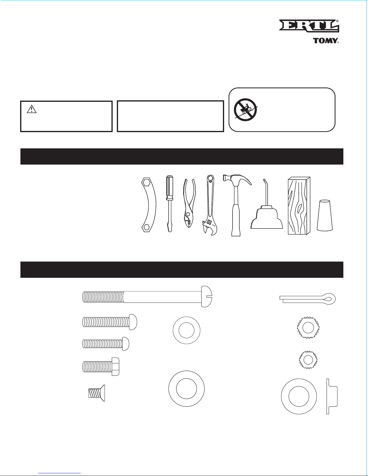
TOOLS REQUIRED:
FAMILIARIZE YOURSELF WITH THIS HARDWARE:
1
/4-20 x 3" Screw
1 Each
1
/4-20 x 3/4" Bolt
6 Each
M4 x
1
/4" Screw
10 Each
15
/16 O.D. Washer
3 Each
3
/4 O.D. Washer
4 Each
Capnut
7
/16"
5 Each
1
/4-20 Kepnut
7 Each
10-24 x 1
1
/4" Screw
1 Each
10-24 x
3
/4" Screw
4 Each
Cotter Key
2 Each
10-24 Kepnut
5 Each
• Wrench in the package,
1
/4-20, 10-24
• Medium Phillips and straight screwdrivers
• Pliers or vise grips
• Crescent wrench or 3/8-, 7/16-, and 1/2-inch
open-end wrenches
• Hammer
• Oil
• Block of wood (2" x 4" x 10")
• Capnut driver
3+
1
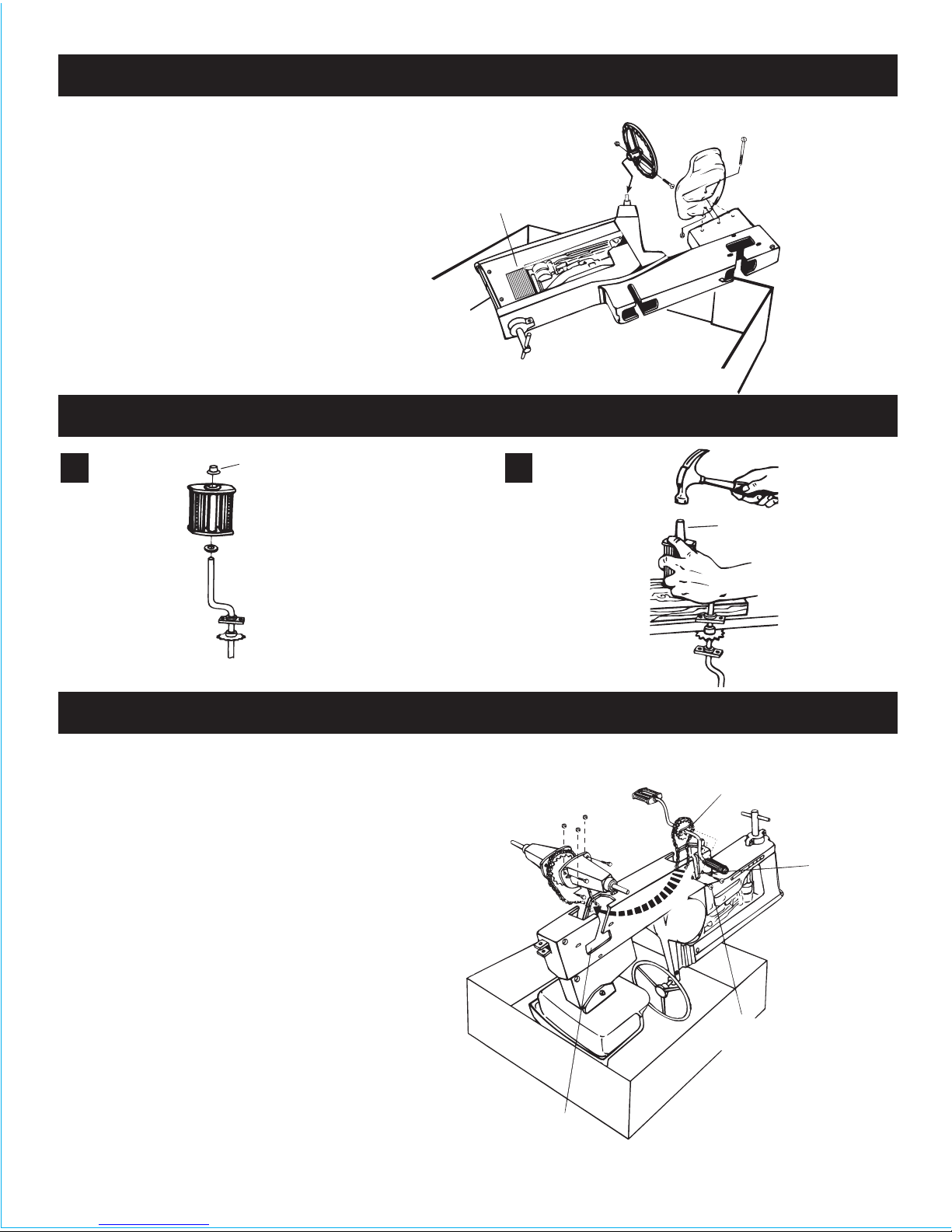
STEP 1
STEP 2
STEP 3
In order to protect your flooring or carpet from
damage or stains it is suggested that you assemble your tractor-cycle in the lid of the shipping
carton. To begin assembly, lay the tractor body
on its side over one wall of carton lid, as shown.
Place steering wheel onto steering shaft. Align
hole in steering shaft with those in steering wheel
and insert 10-24 x 1
1
/4" screw through holes.
Thread 10-24 Kepnut onto screw and tighten.
Place seat into the desired position on seat base
of tractor body, (this can be further adjusted to
suit child after final assembly). Align holes in seat
with desired hole in body and tap the
1
/4-20 x 3"
screw through the holes with a cross screwdriver.
Thread
1
/4-20 Kepnut on and tighten.
10-24 x 1
1
/4" Screw
and Kepnut
Steering wheel
Tractor
body
1
/4-20 x 3" Screw
and Kepnut
Seat
Carton lid
Assemble
pedals to
pedal crank arm.
Slip
3
/4" washer
onto one end of
pedal crank. Slip
pedal onto crank
with circular
recess at top.
Place capnut into
position and
proceed to
Subassembly B.
A
Place pedal
crank over
edge of workbench
or table, as shown.
Using the capnut
driver supplied,
hammer capnut onto
end of pedal crank.
Repeat Subassemblies A and B.
B
Capnut
Capnut
driver
Screws pass through
backing plate here
Pedal slot
10-24 x
3
/4" Screws (2 per side,
each back with 10-24 Kepnut)
Squared end
of axle shaft
Rear axle slot
Pedal
Pedal
crank arm
3
/4"
Washer
Turn tractor over in carton lid so that it rests on seat
and steering wheel. Remove chain from its protective
carton (careful, it’s a bit greasy), drape chain over
assembled pedal crank arm as shown, and feed chain
through “chain tunnel” of body toward rear of tractor,
finally resting pedal crank arm in pedal slot. Reaching
into rear chain access hole of body, lift end of chain out
of body. Pass rear axle through loop of chain; squared
end of rear axle shaft must be on left side of tractor
when upside down (see illustration). Place rear axle in
rear axle slot of body. Pass 10-24 x
3
/4" screws through
body and pedal bearing backing plate, trapping pedal
bearing into cupped recess in body; thread 10-24
Kepnuts onto bolts and tighten. Slide assembled axle
housing (from Subassembly Step 2) over one end of
axle. One at a time, pass
1
/4-20 x 3/4" bolts through
holes in housing and body (this is easier with housing
in full forward position). Thread nuts onto bolts – DO
NOT TIGHTEN. Repeat this assembly for other side.
To adjust chain tension, grab rear axle with fingers on
both sides of gear, pull chain back so that chain is
snug. While holding gear in this position, tighten one
bolt on each side to hold axle in place, then tighten
remainder of bolts. Rotate pedal to check operation
and oil chain liberally while rotating.
1
/4-20 Kepnuts
(3 per side)
1
/4-20 x 3/4" Bolts
(3 per side)
2

STEP 4 STEP 6
STEP 5
Carefully place front axle on edge of workbench
(or a properly protected table) and pound capnut
onto spindle as shown. It is critical to support axle
hubs as shown for proper front wheel alignment.
Repeat for opposite side.
Capnut
driver
Capnut (1 per side)
Tire
Front axle
Woodblock
3
/4" O.D. Washer
3
/4" O.D. Washer
15
/16" washer
NOTE: Use additional
15
/16"
washer(s) to take up end play
Rear wheel
(1 per side)
Cotter key
(1 per side)
Hubcap
(1 per side)
M4 x
1
/4” screws
(3 for each cover)
Pedal guard
Axle guard
Position tractor close to one edge of carton lid.
Find the rear wheel which has a slot for the axle
on one side, and slide it onto the right axle as
shown with the slot to the outside. Slide
15
/16"
O.D. washer onto axle. Insert cotter key through
hole in one side of axle and use a pair of pliers
to bend the prongs around axle. Pound hubcap
into position using a block of wood and a
hammer. Repeat for other side; make sure you
keep the hubcap side of the wheel to the
outside. IMPORTANT! Any end play between
washer and cotter pin of over
1
/8 inch should be
taken up by adding additional
15
/16" O.D. x 17/32"
I.D. washers. Secure rear axle guard into
opening in rear body with 3-M4 x
1
/4" screws.
Repeat for pedal guard. Flip Tractor-Cycle over
and apply decals per directions on the sheet.
Your ERTL Tractor-Cycle is finished and ready
for years of unending play!
3
Snap exhaust stack into hole on top of hood.

PARTS LIST
Ref. No.
COMMON PARTS
Ref. No.
HARDWARE BAG
Ref. No.Description Part No. Description Part No.
Description JOHN DEERE Part No.
*Bagged Sets 099-45467
1
2
3
4
5
6
7
8
28
29
9
10
11
12
13
14
15
16
17
18
19
20
21
22
23
24
25
26
27
1
/4-20 x 3" Screw
10-24 x 1
1
/4" Screw
10-24 x
3
/4" Screw
1
/4-20 x 3/4" Bolt
M4 x
1
/4" Screw
3
/4 O.D. Washer
15
/16 O.D. Washer
Cotter Pin
1
/4-20 Kepnut
10-24 kepnut
7
/16" Capnut
Steering Wheel
Pedal
Hitch Pin Assembly
Pedal Crank Arm
Bushing
Hubcap
Chain
Rear Axle and
Sprocket
Body
Pedal Guard
Axle Guard
Front Wheels
Rear Axle Hub
Rear ldle Wheel
Rear Drive Wheel
Seat
Decal Sheet
Exhaust Stack
Grille
P10333
P10045
P10050
P10039
P10040
P10367
P10594
P10595
P10596
P10030
P10080
P10017
P10335
P10032
P10001
P10330
P10051
P10473*
This item carries a 1 year warranty.
To purchase replacement parts, please visit
our website at www.learningcurveshop.com.
For replacement parts within our 1 year
limited warranty, please call 800-704-8697
4
© TOMY
Oak Brook, Illinois 60523, USA
All Rights Reserved. Made in China.
Please retain this instruction sheet for future reference.
17
25
8
3
21
21
2
28
29
21
21
 Loading...