

Erreka Topo Swing Gate Opener User Manual
INDEX
General safety instructions 42
Symbols used in this manual__________________________________ 42
Importance of this manual ___________________________________ 42
Envisaged use______________________________________________ 42
Installer's qualifications ______________________________________ 42
Automatic gate safety elements_______________________________ 42
Description of the product 43
Elements of the complete installation __________________________ 43
General characteristics of the operator _________________________ 44
Main operator parts_________________________________________ 44
General characteristics of the operator _________________________ 45
Manual operation __________________________________________ 45
Declaration of conformity ____________________________________ 46
English
Unpacking and content 47
Unpacking_________________________________________________ 47
Content___________________________________________________ 47
Installation 48
Necessary tools_____________________________________________ 48
Necessary materials _________________________________________ 48
Initial conditions and checks __________________________________ 49
Installing the base box_______________________________________ 50
Installation and adjustment of the mechanism and of the gate _____ 51
Final checks________________________________________________ 58
Maintenance and diagnosis of failures 59
Maintenance_______________________________________________ 59
Failure diagnosis____________________________________________ 59
Spare parts ________________________________________________ 60
Scrap _____________________________________________________ 60
TOPOTOC.fm - 3/11/11
TOPO underground electromechanical operator 41
GENERAL SAFETY INSTRUCTIONS
1
This manual uses symbols to highlight specific texts. The
functions of each symbol are explained below:
SYMBOLS USED IN THIS MANUAL
Failure to respect the safety warnings could
lead to accident or injury.
Work sequences or procedures.
2
IMPORTANCE OF THIS MANUAL
Read this manual in its entirety before carrying
out the installation, and obey all instructions.
Failure to do so may result in a defective
installation, leading to accidents and failures.
3
This device has been designed for installation as part of
an automatic opening and closing system for swing
gates.
ENVISAGED USE
Important details which must be respected for
correct assembly and operation.
Additional information to help the installer.
} Information on care for the environment.
Moreover, this manual provides valuable
information which will help you to carry out
installation more efficiently.
This manual is an integral part of the product. Keep
for future reference.
Failure to install or use as indicated in this
manual is inappropriate and hazardous, and
could lead to accidents or failures.
4
INSTALLER'S QUALIFICATIONS
The installation should be completed by a
professional installer, complying with the
following requirements:
• He/she must be capable of carrying out
mechanical assemblies in doors and gates,
choosing and implementing attachment
systems in line with the assembly surface
(metal, wood, brick, etc) and the weight and
effort of the mechanism.
5
This device complies with all current safety regulations.
However, the complete system comprises, apart from
the operator referred to in these instructions, other
elements which should be acquired separately.
AUTOMATIC GATE SAFETY ELEMENTS
The safety of the complete installation depends on
all the elements installed. Install only Erreka
• He/she must be capable of carrying out
simple electrical installations in line with the
low tension regulations and applicable
standards.
• He/she must be capable of carrying out
simple masonry work (digging of pits,
channels, preparation of cement).
The installation should be carried out bearing
in mind standards EN 13241-1 and EN 12453.
components in order to guarantee proper
operation.
Respect the instructions for all the elements
positioned in the installation.
We recommend installing safety elements.
For further details, see “Elements of the complete
installation” on page 43.
42 Installation manual
Seguridad_02 v1.7.fm - 3/11/11
DESCRIPTION OF THE PRODUCT
English
1
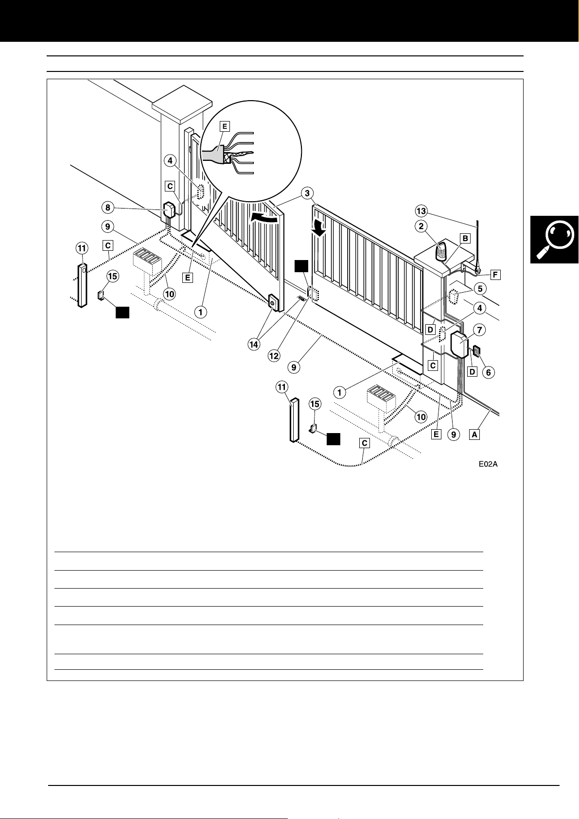
ELEMENTS OF THE COMPLETE INSTALLATION
The TC stopper must be installed in all
cases.
MOTOR
2
2
8m
2x1mm
ENCODER
2x0,5mm
TA
INSTALLATION COMPONENTS:
1 Operator
2 Flashing lamp
3 Gate
4 Exterior photocells
5 Key selector
6 Wall button
7 Control panel
8 Connections case
9 Underground electrical installation
10 Drainage ducts
11 Interior photocells
12 In-ground central stop
13 Aerial antenna
14 Electrolock
15 Opening external stopper
ELECTRICAL CABLING:
Element Nº threads x section Maximum length
A: General power supply 3x1.5mm
B: Flashing lamp 2x0.5mm
C: Photocells (Tx / Rx) 2x0.5mm
D: Key selector 2x0.5mm
E: Operator (motor + encoder)
F: Antenna Coaxial cable 50k (RG-58/U) 5m
Hose (2x1mm
screened hose 2x0.5mm
2
2
2
/ 4x0.5mm
2
2
+ interior
2
2
)
The TA opening external stopper is
only necessary with the 180º opening
mechanism (chain).
TC
TA
30m
20m
30m
25m
8m (maximum 25m with 2x2.5mm
cable)
2
Fig. 1 Elements of the complete installation
The safe and correct operation of the
installation is the responsibility of the installer.
Only use control panel VIVO-D201(M). We do
not recommend using this operator with control
panels which are not produced by Erreka.
Descripción_02 v1.7.fm - 3/11/11
The in-ground central stop (12) is an essential
element.
For greater safety, Erreka recommends installing the
photocells (4) and (11).
TOPO underground electromechanical operator 43
DESCRIPTION OF THE PRODUCT
2
The TOPO operator is constructed to form part of a
swing gate automation system, also replacing the lower
hinge of the gate.
It comprises a galvanised steel base box, buried
underneath the gate, which contains the motor and the
operation mechanism. Allows a maximum opening of
110º (or 180º with the NBKIT-180 kit).
This operator, along with its corresponding Erreka
control panel, allow the implementation of a soft stop
system, with the speed slowing down at the end of the
closing and opening operations.
3
GENERAL CHARACTERISTICS OF THE OPERATOR
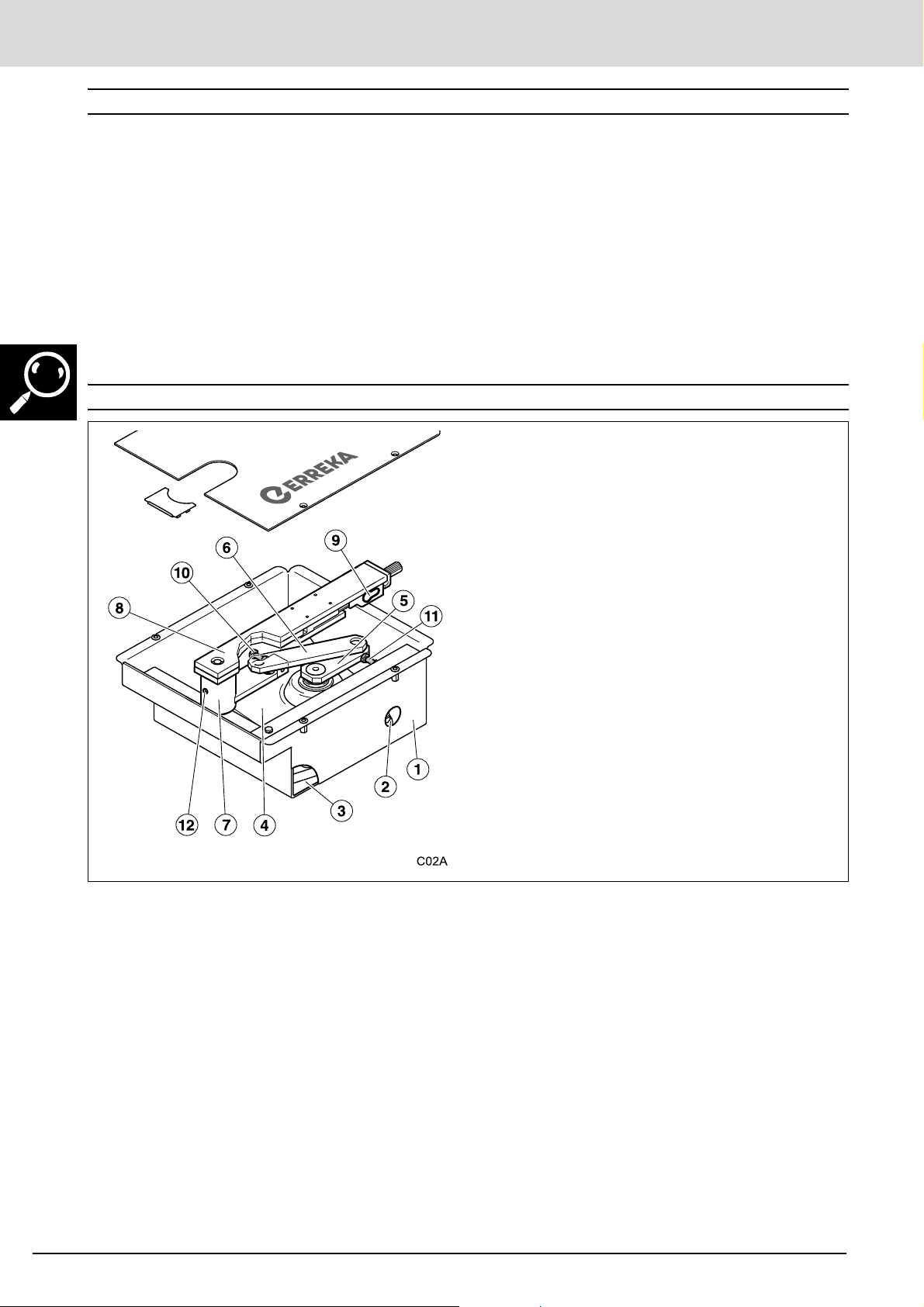
MAIN OPERATOR PARTS
The motor is irreversible, thus guaranteeing the
mechanical locking of the gate. However, for leaf
lengths of over 2.5m we recommend using an
electrolock.
The operator has an unlocking mechanism in order to
operate the gate manually in the event of failure of the
electricity supply.
This operator allows us to fulfil the requirements of
standard EN 12453 without the use of peripheral
elements.
Components:
1 Galvanised steel base box
2 Orifice for electrical duct
3 Orifice for drainage
4 Motor gear box
5 Motor arm
6 Intermediate arm
7 Driven arm (lower)
8 Driven arm (upper)
9 Unlocking mechanism
10 Mechanical stop in opening
11 Mechanical stop in closing
12 Lubricator
Fig. 2 Main parts
Cabling:
• Red and blue cables: motor
• Brown cable: encoder power supply (V+)
• Green cable: encoder signal (SNG1)
• Mesh: encoder mass (GND)
44 Installation manual
Descripción_02 v1.7.fm - 3/11/11
DESCRIPTION OF THE PRODUCT
4
Model TOPO
Power supply (Vdc) 24
Intensity (A) 6
Power consumed (W) 144
Protection class (IP) 67
Available torque (Nm) 380
Output speed (rpm) adjustable
Opening time 90º (s) 16-30
Self locking Yes
Service temperature (ºC) -25/+70
Duty cycles (%) 80
Base box dimension (mm) 381x336x152
Motor weight (kg) 9,5
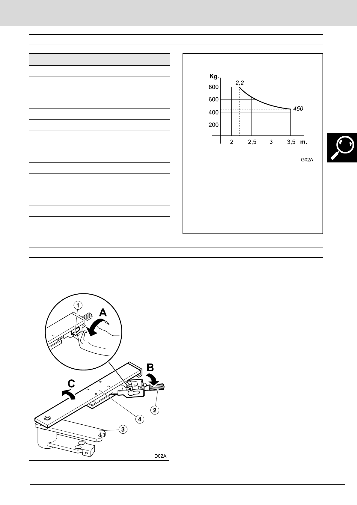
Size and weight of the gate See chart
Use Intensive
GENERAL CHARACTERISTICS OF THE OPERATOR
Limits on use
Only use the chart
VIVO-D201(M).
We recommend using an electrolock for
leaf lengths of over 2.5m.
Values for orientation purposes. The form
of the leaf and the presence of wind may
bring notable differences in the values of
the chart.
5
MANUAL OPERATION
In the event of need, the gate may be operated manually, acting first on the unlocking mechanism.
Unlock
1 Introduce the key in the lock (1) of the unlocking
system and turn the key towards the axle of the gate
(A).
2 Pull on the unlocking lever (2), making it rotate 90º
(B).
The arm (3) is unlocked from the base (4).
3
3 Move the gate manually (C).
Descripción_02 v1.7.fm - 3/11/11
TOPO underground electromechanical operator 45
DESCRIPTION OF THE PRODUCT
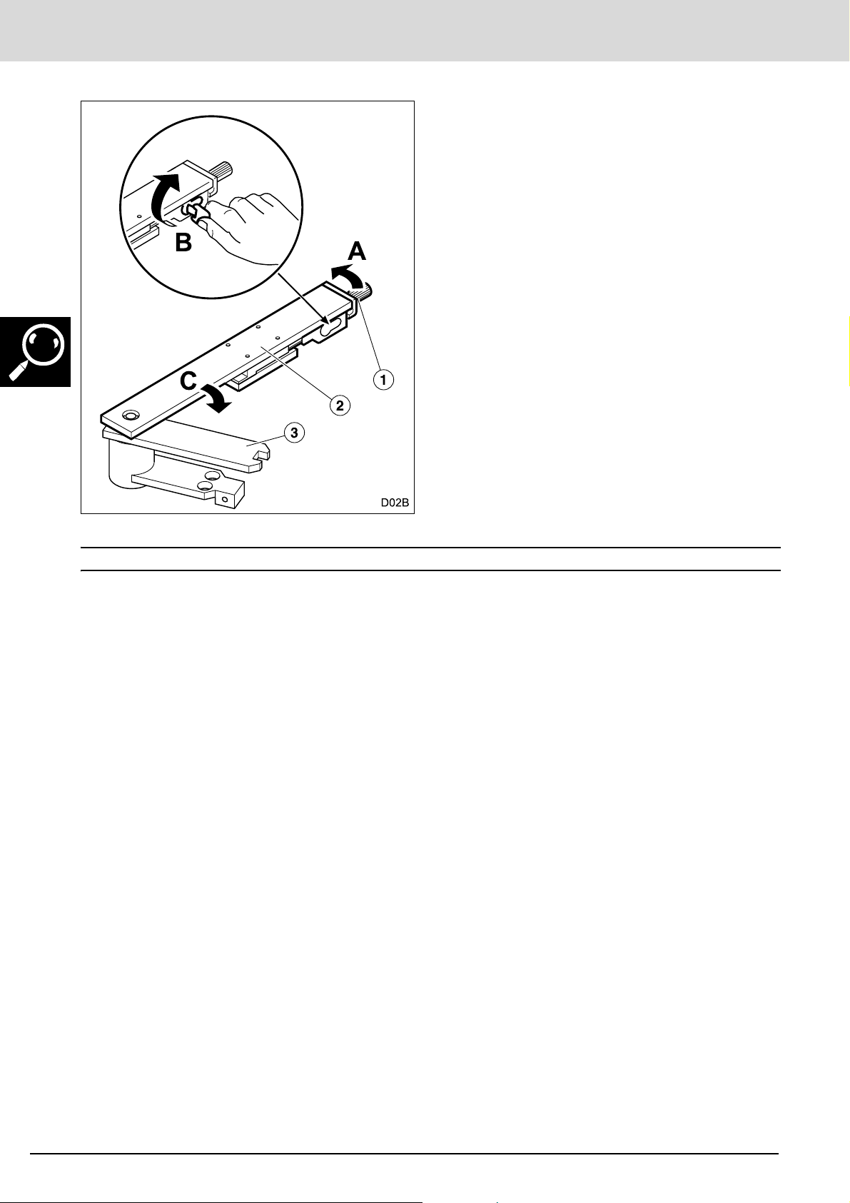
Lock
In order to restart automatic operation of the
system, carry out the following operations:
1 Rotate the unlocking lever (1) until it is located
underneath the base (2) (A).
2 Rotate the key as shown in figure (B).
3 Move the gate until its base (2) is aligned with the
arm (3) (C).
6
Erreka Automatismos declares that the TOPO operator
has been designed for use in a machine or for assembly
along with other elements in order to form a machine
in line with Directive 2006/42/EC.
The TOPO electromechanical operator allows
installations in line with Standards EN13241-1 and
EN12453.
DECLARATION OF CONFORMITY
The TOPO electromechanical operator complies with
safety legislation in line with the following directives
and standards:
• 2006/95/EC (low voltage)
• 2004/108/EC (electromagnetic compatibility)
• UNE-EN 60335-1 and UNE-EN 60335-2-103
46 Installation manual
Descripción_02 v1.7.fm - 3/11/11
 Loading...