

Erreka Lince Swing Gate Opener User Manual
INDEX
General safety instructions 42
Symbols used in this manual__________________________________ 42
Importance of this manual ___________________________________ 42
Envisaged use ______________________________________________ 42
Installer's qualifications ______________________________________ 42
Automatic operation safety elements __________________________ 42
Description of the product 43
Elements of the complete installation __________________________ 43
Actuator characteristics ______________________________________ 44
Actuator parts _____________________________________________ 45
Operation modes ___________________________________________ 46
Behaviour in the face of an obstacle ___________________________ 46
Manual operation __________________________________________ 47
Declaration of conformity ____________________________________ 47
English
Unpacking and content 48
Unpacking_________________________________________________ 48
Content___________________________________________________ 48
Installation 49
Tools and materials _________________________________________ 49
Initial conditions and checks __________________________________ 49
Actuator installation ________________________________________ 50
Electrical connections _______________________________________ 52
Start up and programming 54
Connection to the grid ______________________________________ 54
Display____________________________________________________ 54
Programming sequence______________________________________ 55
Checking the impact force ___________________________________ 58
Final checks________________________________________________ 58
Maintenance and diagnosis of failures 59
Maintenance_______________________________________________ 59
Operations Counter _________________________________________ 59
Failure diagnosis____________________________________________ 60
Scrap _____________________________________________________ 60
LINCETOC.fm - 2/4/09
LINCE actuator for sliding gates 41

GENERAL SAFETY INSTRUCTIONS
1
This manual uses symbols to highlight specific texts. The
functions of each symbol are explained below:
SYMBOLS USED IN THIS MANUAL
Failure to respect the safety warnings could
lead to accident or injury.
O Instructions which must be followed to prevent
deterioration.
2
3
This device has been designed for installation as part of
an automatic opening and closing system for sliding
doors and gates.
IMPORTANCE OF THIS MANUAL
Read this manual in its entirety before carrying
out the installation, and obey all instructions.
Failure to do so may result in a defective
installation, leading to accidents and failures.
ENVISAGED USE
Work sequences or procedures.
Important details which must be respected for
correct assembly and operation.
Additional information to help the installer.
} Information on care for the environment.
Moreover, this manual provides valuable
information which will help you to carry out
installation more efficiently.
This manual is an integral part of the product. Keep
for future reference.
Failure to install or use as indicated in this
manual is inappropriate and hazardous, and
could lead to accidents or failures.
This device is not suitable for installation in
inflammable or explosive environments.
4
INSTALLER'S QUALIFICATIONS
The installer shall be responsible for ensuring
the installation is set up for its envisaged use.
The installation should be completed by a professional installer, complying with the following
requirements:
• He/she must be capable of carrying out
mechanical assemblies in doors and gates,
choosing and implementing attachment
systems in line with the assembly surface
(metal, wood, brick, etc) and the weight and
effort of the mechanism.
5
This device complies with all current safety regulations.
However, the complete system comprises, apart from
the actuator referred to in these instructions, other
elements which should be acquired separately.
AUTOMATIC OPERATION SAFETY ELEMENTS
The safety of the complete installation depends on
all the elements installed. Install only Erreka
components in order to guarantee proper
operation.
• He/she must be capable of carrying out
simple electrical installations in line with the
low voltage regulations and applicable
standards.
The installation should be carried out bearing
in mind standards EN 13241-1 and EN 12453.
Respect the instructions for all the elements
positioned in the installation.
We recommend installing safety elements.
For further details, see “Fig. 1 Elements of the
complete installation” on page 43.
42 Installation Manual
Seguridad_V.00.fm - 6/2/09
DESCRIPTION OF THE PRODUCT
English
1
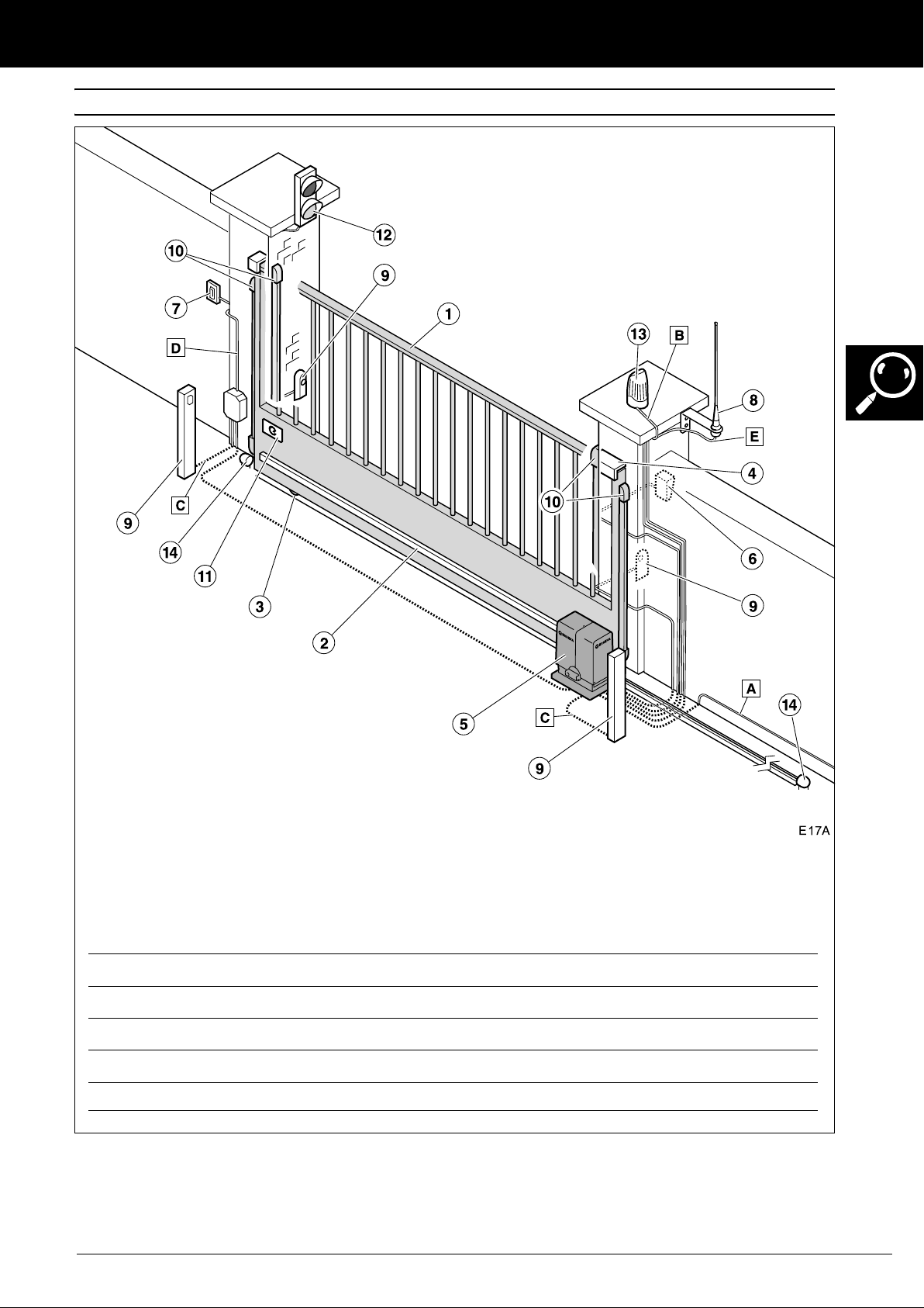
ELEMENTS OF THE COMPLETE INSTALLATION
1 Gate
2 Rack
3 Lower track and guide wheels
4 Upper guide
5 Actuator with control panel
6 Magnetic key or proximity key reader
7 Wall button/key selector
8 Antenna
9 Photocells
ELECTRICAL CABLING:
Element Nº threads x section Maximum length
A: General power supply 3x1.5mm
B: Flashing light 2x0.5mm
C: Photocells (Tx / Rx) 2x0.5mm
D: Button/wall key 2x0.5mm
E: Antenna Screened cable 5m
Fig. 1 Elements of the complete installation
The safe and correct operation of the
installation is the responsibility of the installer.
10 Mechanical strip
11 Identification plate
12 Signal light
13 Flashing light
14 Gate stopper
2
2
2
/ 4x0.5mm
2
2
For greater safety, Erreka recommends installing
photocells (9) and safety strips (10).
30m
20m
30m
50m
Descripcion_V.02.fm - 25/6/09
LINCE actuator for sliding gates 43

DESCRIPTION OF THE PRODUCT
2
The LINCE actuators are constructed to form part of a
sliding gate automation system.
This control panel, with built in control panel, is
equipped with a soft stop system which reduces speed
at the end of the opening and closing operations, in
order to prevent impacts and bangs to the gate.
ACTUATOR CHARACTERISTICS
General characteristics
• LIS424 - LIS624: Power supply 230Vac, 50Hz,
earthed
• LIS424
• Control of the travel by way of encoder
• Adjustable speed
• Adjustable maximum force
M - LIS624M: Power supply 125Vac, 60Hz,
earthed
Notable characteristics
Self-testing of photocells (programmable)
The panel tests the photocells before starting each
operation. Should a failure be detected, the operation
is not carried out.
Garage light (programmable)
The garage light time can be programmed between 3
and 240 seconds. Time begins to count when operation
starts.
Flashing light
The light remains on during the opening and closing
operations.
This actuator allows us to fulfil the requirements of
standard EN 12453 without the use of peripheral
elements.
• Adjustable standby time in automatic cycle
• Opening and closing safety device terminals (safety
strips or photocells)
• Connector for plug-in receiver
• Connector for light signal card (AEPS1-001)
• 24Vdc terminal for peripheral connection
• Emergency battery input
SCA Light
A 24V SCA light can be connected.
• The light remains off when the gate is closed.
• The SCA light remains on statically when the gate is
open.
• During opening, the SCA light flashes every second.
• During closing, the SCA light flashes every half a
second.
Soft stop function (programmable)
Function which reduces the speed of the motor at the
end of the opening and closing operation.
The light goes off when the operation concludes. The
light goes off whenever operation is interrupted at a
specific point.
Operation warning function (programmable)
This function delays the start of operation by three
seconds, during which time the flashing light comes on
to warn us that operation is about to begin.
Signal light
A signal light can be connected if the AEPS1-001 card
is installed. Using colour lights, these will indicate the
suitability or otherwise of crossing the gate.
• Off: gate closed
• Green light: gate open, free passage
• Red light: gate in movement, passage forbidden
• Intermittent green light: open gate about to close (in
automatic mode)
24Vdc battery (bA)
It is possible to connect a battery in order for the
actuator to continue working in the event of a drop in
power. The battery will be recharged when the
electricity supply is restored.
Reset (rS)
Reset is the closed gate position search at slow speed.
The display shows rS.
The actuator carries out a reset in the following cases:
• When the electricity supply is restored following
interruption, and an operation device is activated
• When the actuator for manual operation is unlocked
and locked again
• When the gate collides with an obstacle three
consecutive times
Descripcion_V.02.fm - 25/6/09
44 Installation Manual

DESCRIPTION OF THE PRODUCT
Technical characteristics of the actuator
Model LIS424 LIS424M LIS624 LIS624M
Power supply (V/Hz) 230/50 125/60 230/50 125/60
Power consumed (W) 110 110
Motor voltage (Vdc) 24 24
Protection grade (IP) 45 45
Maximum torque (Nm) 10 15
Service temperature (ºC) -20/ +55 -20/ +55
Weight (Kg) 9 9
Max gate weight 400 8650
Use Intensive Intensive
Maximum speed (m/min) 15 11,5
3
ACTUATOR PARTS
1 Upper cover
2 Terminals cover
3 Circuit cover
4 Screw covers
5 Programming buttons and display
6 Position for batteries (optional, not supplied)
7 Unlocking handle (for manual operation)
8 Connection strip
9 General cut-out
For further information on the display indications,
see “Display” on page 54.
For further information on the programming
buttons, see “Programming sequence” on
page 55.
Descripcion_V.02.fm - 3/7/09
LINCE actuator for sliding gates 45

DESCRIPTION OF THE PRODUCT
4
OPERATION MODES
Automatic mode (F101)
Opening: this begins by activating the operation device
(emitter, magnetic key, key selector, etc).
• Community Opening: during opening, the control
panel does not obey the operation device
commands (configurable in the advanced options
menu, see “Advanced Functions Programming (D1=
“A”)” on page 57).
Semi-automatic mode (F102)
Opening: this begins by activating the operation device
(emitter, magnetic key, key selector, etc).
• Step-by-step opening: if the control device is
operated during opening, the gate halts
(programmable in the advanced options menu, see
“Advanced Functions Programming (D1= “A”)” on
page 57).
The display shows pause situation PA.
Standby: the gate remains open during the
programmed time.
• If the control device or the photocells are operated
during standby, standby time restarts (configurable
in the advanced options menu, see “Advanced
Functions Programming (D1= “A”)” on page 57.
Close:the closing operation starts automatically once
standby time is finished.
If, during closing, the operation device is activated,
the gate inverts operation direction and opens
completely.
Standby: the gate remains open indefinitely until the
control device is operated.
Close: the closing process starts up by using the
operation device.
If, during closing, the operation device is activated,
the actuator inverts the movement and the gate
opens.
The gate closes when the operation device is activated
again.
5
The gate can detect an obstacle in two ways:
A-
BEHAVIOUR IN THE FACE OF AN OBSTACLE
Detection by photocell or safety strip
Opening safety device (SG.A)
During opening: if, during opening, the opening
safety device (SG.A) is activated, the gate inverts
operation direction and slightly closes. The gate
remains on standby until an operation command is
received and the display shows PAC4.
During closing: if, during closing, the opening safety
device (SG.A) is activated, the gate continues to close.
B- Direct detection (built-in safety)
During opening
If, during opening, the gate collides with an obstacle, it
inverts operation direction and slightly closes. The gate
remains on standby until an operation command is
received and the display shows PAF1 or PAE1. The gate
closes when the operation device is used.
Closing safety device (SG.C)
During opening: if, during opening, the closing safety
device (SG.C) is activated, the gate continues to open.
During closing: if, during closing, the closing safety
device (SG.C) is activated, the gate inverts operation
direction and opens completely. The display shows
OPC5.
During closing
If, during closing, the gate collides with an obstacle, it
inverts operation direction and opens completely. The
display shows OPF1 or OPE1.
46 Installation Manual
Descripcion_V.02.fm - 25/6/09
 Loading...