

Erreka Ciclon Swing Gate Opener User Manual
INDEX
General safety instructions 34
Symbols used in this manual__________________________________ 34
Importance of this manual ___________________________________ 34
Envisaged use______________________________________________ 34
Installer's qualifications ______________________________________ 34
Automatic gate safety elements_______________________________ 34
Description of the product 35
Elements of the complete installation __________________________ 35
General characteristics of the operator _________________________ 36
Main operator parts_________________________________________ 36
General characteristics of the operator _________________________ 37
Manual operation __________________________________________ 37
Declaration of conformity ____________________________________ 38
English
Unpacking and content 39
Unpacking_________________________________________________ 39
Content___________________________________________________ 39
Installation 40
Necessary tools_____________________________________________ 40
Necessary materials _________________________________________ 40
Initial conditions and checks __________________________________ 40
Installing the operator _______________________________________ 41
Final checks________________________________________________ 47
Maintenance and diagnosis of failures 48
Maintenance_______________________________________________ 48
Failure diagnosis____________________________________________ 48
Scrap _____________________________________________________ 48
Spare parts ________________________________________________ 48
CICLON_TOC.fm - 29/2/08
CICLÓN Electromechanical Operator 33

GENERAL SAFETY INSTRUCTIONS
1
This manual uses symbols to highlight specific texts. The
functions of each symbol are explained below:
SYMBOLS USED IN THIS MANUAL
Failure to respect the safety warnings could
lead to accident or injury.
Work sequences or procedures.
2
3
This device has been designed for installation as part of
an automatic opening and closing system for swing
gates.
IMPORTANCE OF THIS MANUAL
Read this manual in its entirety before carrying
out the installation, and obey all instructions.
Failure to do so may result in a defective
installation, leading to accidents and failures.
ENVISAGED USE
Important details which must be respected for
correct assembly and operation.
Additional information to help the installer.
} Information on care for the environment.
Moreover, this manual provides valuable
information which will help you to carry out
installation more efficiently.
This manual is an integral part of the product. Keep
for future reference.
Failure to install or use as indicated in this
manual is inappropriate and hazardous, and
could lead to accidents or failures.
This device is not suitable for installation in
inflammable or explosive environments.
4
INSTALLER'S QUALIFICATIONS
The installation should be completed by a
professional installer, complying with the
following requirements:
• He/she must be capable of carrying out
mechanical assemblies in doors and gates,
choosing and implementing attachment
systems in line with the assembly surface
5
This device complies with all current safety regulations.
However, the complete system comprises, apart from
the operator referred to in these instructions, other
elements which should be acquired separately.
AUTOMATIC GATE SAFETY ELEMENTS
The safety of the complete installation depends on
all the elements installed. Install only Erreka
(metal, wood, brick, etc) and the weight and
effort of the mechanism.
• He/she must be capable of carrying out
simple electrical installations in line with the
low tension regulations and applicable
standards.
The installation should be carried out bearing
in mind standards EN 13241-1 and EN 12453.
components in order to guarantee proper
operation.
Respect the instructions for all the elements
positioned in the installation.
We recommend installing safety elements.
For further details, see “Elements of the complete
installation” on page 35.
34 Installation manual
Seguridad_03 v1.3.fm - 5/3/08
DESCRIPTION OF THE PRODUCT
English
1
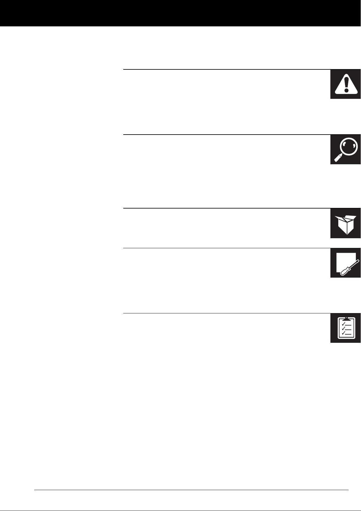
ELEMENTS OF THE COMPLETE INSTALLATION
INSTALLATION COMPONENTS:
1Operator
2 Flashing lamp
3 Gate
4 Exterior photocells
5Key selector
6 Wall button
7 Control panel
8 Connections case
9 Electrical installation
10 Interior photocells
11 Electrolock
(obligatory in model CLS210)
12 In-ground central stop
13 Aerial antenna
ELECTRICAL CABLING:
Element Nº threads x section Maximum length
A: General power supply 3x1.5mm
B: Flashing lamp 2x0.5mm
C: Photocells 2x0.5mm
D: Key selector 2x0.5mm
E: Operator 9x0.75mm
F: Antenna Shielded cable 5m
2
2
2
2
2
30m
20m
30m
25m
20m
Fig. 1 Elements of the complete installation
The safe and correct operation of the
installation is the responsibility of the installer.
Descripcion_03 v1.3.fm - 4/3/08
For greater safety, Erreka recommends installing the
photocells (4) and (10).
CICLÓN Electromechanical Operator 35
DESCRIPTION OF THE PRODUCT
2
The CLS210/CLS210F operator is constructed to form
part of a swing gate automation system.
It comprises a metal body, which contains the motor
and a planetary gears box. Model CLS210F also has a
brake and unlocking key to operate the gate manually
in the event of failure of the electricity supply. Allows a
maximum opening of approximately 130°.
This operator, along with its corresponding Erreka
control panel, allow the implementation of a soft stop.
3
GENERAL CHARACTERISTICS OF THE OPERATOR
MAIN OPERATOR PARTS
system, with the speed slowing down at the end of the
closing and opening operations.
With model CLS210 it is necessary to install an electrical
lock, as is also the case with model CLS210F for leaf
lengths of over 1.8m.
Operator CLS210/CLS210F can be installed with an
articulated arm or with a sliding arm.
This operator allows us to fulfil the requirements of
standard EN 12453 without the use of peripheral
elements.
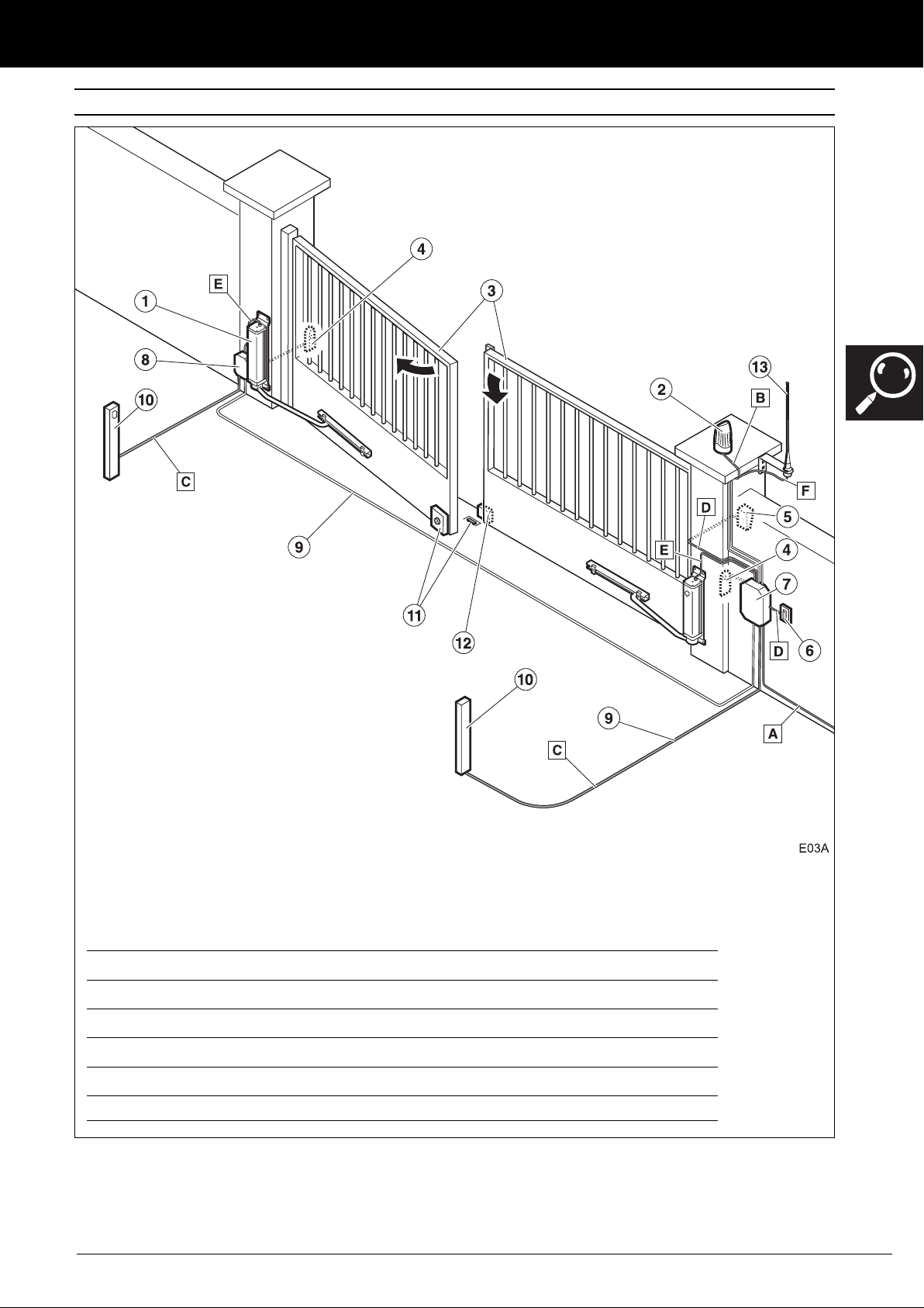
Components:
1 Operator body
2 Lock for unlocking (only
model CLS210F)
3 Drag wheel
4 Wall support
5 Arm (not included with the
operator)
Fig. 2 Main components
Wires:
• Grey wire: motor (common)
• Brown wire: motor
(rotation 1)
• Black wire: motor (rotation 2)
• Orange wire: brake
• Violet wire: brake
• Red wire: power supply (+)
encoder
• White wire: power supply (-)
encoder
• Blue wire: encoder signal
• Yellow/green wire: earth
36 Installation manual
Descripcion_03 v1.3.fm - 4/3/08
DESCRIPTION OF THE PRODUCT
4
Model CLS210 CLS210F
Power supply (V/Hz) 230/50
Intensity (A) 1
Power consumed (W) 230
Capacitor (μF) 5
Protection grade (IP) 54
Available torque (Nm) 220
Output speed (rpm) 1,3
Opening time 90º (s) 12
Self locking No Yes
Service temperature (ºC) -20/+60
Duty cycles (%) 20
Operator dimensions (mm) 88 x 88 x 470
Weight (Kg). 13
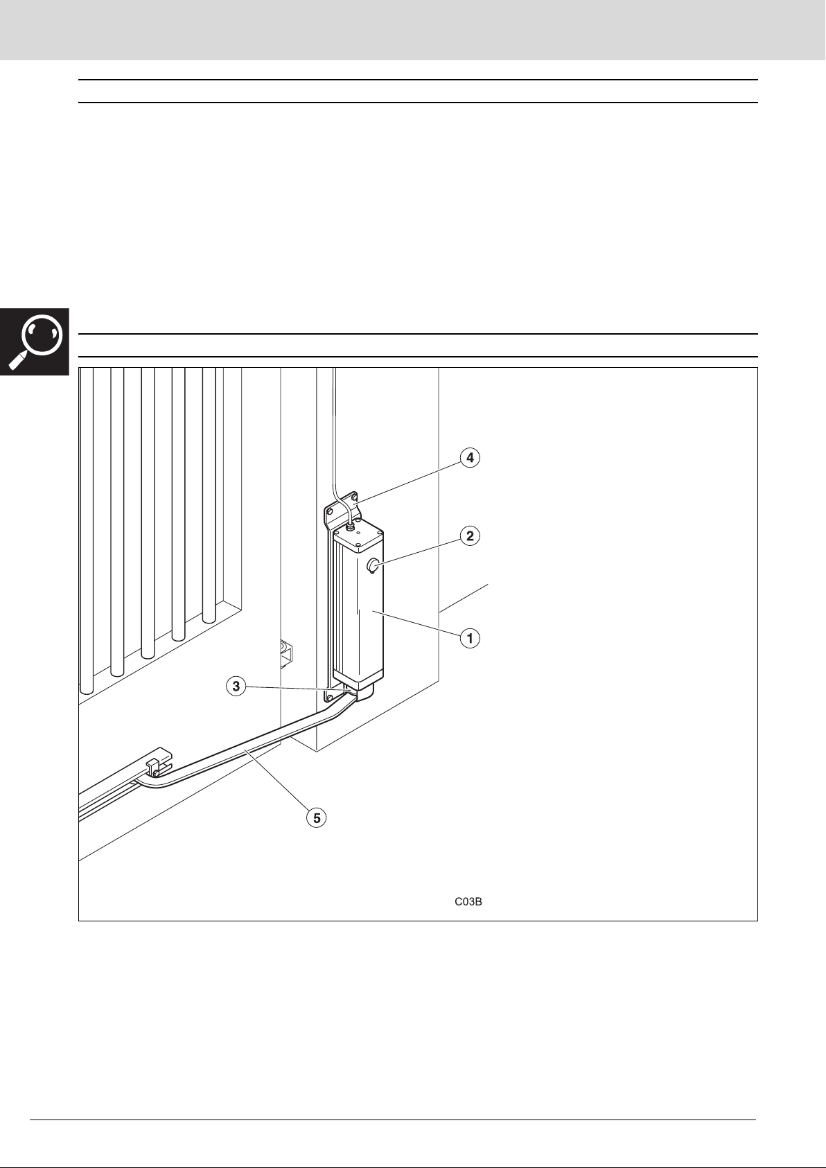
Gate size and weight See chart
GENERAL CHARACTERISTICS OF THE OPERATOR
Limits on use
We recommend using the chart
65-AEP20PIL9.
We recommend using an electrolock for leaf
lengths of over 1.8m.
Values for orientation purposes. The form of
the leaf and the presence of strong wind may
bring notable differences in the values of the
chart.
5
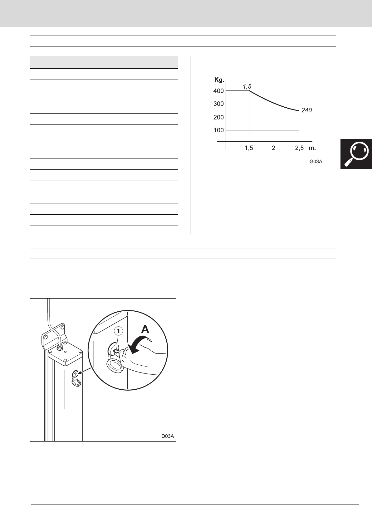
MANUAL OPERATION
In the event of need, the gate may be operated manually. In model CLS210F it is necessary to first run the
unlocking mechanism.
Unlock (only for model CLS210F)
1 Introduce the key in the unlocking system lock and
turn the unlocking key (1) 90º anti-clockwise (A).
2 Move the gate manually.
3
Descripcion_03 v1.3.fm - 4/3/08
CICLÓN Electromechanical Operator 37
 Loading...