

Erreka Arc Swing Gate Opener User Manual
INDEX
General Safety Instructions 26
Symbols used in this manual__________________________________ 26
Importance of this manual ___________________________________ 26
Envisaged use______________________________________________ 26
Installer's qualifications ______________________________________ 26
Automatic operation safety elements __________________________ 26
Description of the product 27
Elements of the complete installation __________________________ 27
Actuator characteristics ______________________________________ 28
Declaration of conformity ____________________________________ 28
Manual operation __________________________________________ 29
Content of the package _____________________________________ 29
English
Installation 30
Tools and materials _________________________________________ 30
Initial conditions and checks __________________________________ 30
Unpacking_________________________________________________ 31
Actuator installation ________________________________________ 31
Electrical connections _______________________________________ 33
Installation of release box for manual drive _____________________ 34
Final checks________________________________________________ 34
Maintenance and diagnosis of failures 35
Maintenance_______________________________________________ 35
Failure diagnosis____________________________________________ 35
Scrap _____________________________________________________ 35
Spare parts ________________________________________________ 35
ARC_TOC.fm - 27/3/09
ARC electro-mechanical actuator 25

GENERAL SAFETY INSTRUCTIONS
1
This manual uses symbols to highlight specific texts. The
functions of each symbol are explained below:
SYMBOLS USED IN THIS MANUAL
Failure to respect the safety warnings could
lead to accident or injury.
2
3
This device has been designed for installation as part of
an automatic opening and closing system for swing
doors and gates.
IMPORTANCE OF THIS MANUAL
Read this manual in its entirety before carrying
out the installation, and obey all instructions.
Failure to do so may result in a defective
installation, leading to accidents and failures.
ENVISAGED USE
This device is not suitable for installation in
inflammable or explosive environments.
Important details which must be respected for
correct assembly and operation.
Additional information to help the installer.
} Information on care for the environment.
Moreover, this manual provides valuable
information which will help you to carry out
installation more efficiently.
This manual is an integral part of the product. Keep
for future reference.
Failure to install or use as indicated in this
manual is inappropriate and hazardous, and
could lead to accidents or failures.
The installer shall be responsible for ensuring
the installation is set up for its envisaged use.
4
INSTALLER'S QUALIFICATIONS
Installation should be completed by a professional installer, complying with the following
requirements:
• He/she must be capable of carrying out
mechanical assemblies in doors and gates,
choosing and implementing attachment
systems in line with the assembly surface
(metal, wood, brick, etc) and the weight and
effort of the mechanism.
• He/she must be capable of carrying out
simple electrical installations in line with the
low voltage regulations and applicable
standards.
The installation should be carried out bearing in mind standards EN 13241-1 and EN 12453.
5
This device complies with all current safety regulations.
However, the complete system comprises, apart from
the actuator referred to in these instructions, other
elements which should be acquired separately.
The safety of the complete installation depends on
AUTOMATIC OPERATION SAFETY ELEMENTS
all the elements installed. Install only Erreka
components in order to guarantee proper
operation.
Respect the instructions for all the elements
positioned in the installation.
We recommend installing safety elements.
For further details, see “Fig. 1 Elements of the
complete installation” on page 27.
26 Installation Manual
Seguridad_64 v0.0.fm - 27/3/09
DESCRIPTION OF THE PRODUCT
English
1
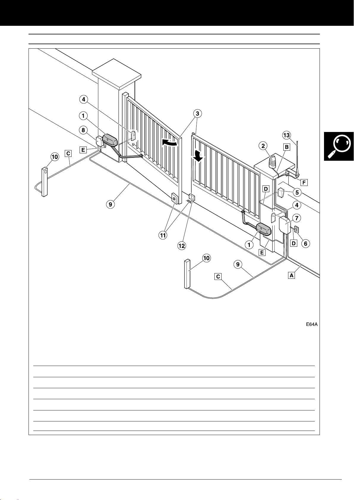
ELEMENTS OF THE COMPLETE INSTALLATION
INSTALLATION COMPONENTS:
1Actuator
2 Flashing light
3 Gate
4 Exterior photocells
5Key selector
6 Wall button
7 Control panel
8 Connections box
9 Electrical installation
10 Interior photocells
11 Electrolock
12 Closing stopper
13 Antenna
We recommend using the ABC2MARC9 control panel for the ARS24C, and
the AEP20TOP for the AR220C.
ELECTRICAL CABLING:
Element Nº threads x section Maximum length
A: General power supply 3x1.5 mm
B: Flashing light 2x0.5 mm
C: Photocells (Tx / Rx) 2x0.5 mm
D: Button or key selector 2x0.5 mm
E: Motor/encoder 2x1 mm
F: Antenna Screened cable 5 m
2
2
2
/ 4x0.5mm230 m
2
2
/ 3x0.5mm
2
30 m
20 m
25 m
8 m (maximum 25 m with cable 2x2.5 mm2/ 3x0.5 mm
2
Fig. 1 Elements of the complete installation
The safe and correct operation of the
installation is the responsibility of the installer.
Descripcion_64 v0.0.fm - 6/4/09
For greater safety, Erreka recommends installing the
photocells (4) and (10).
ARC electro-mechanical actuator 27
DESCRIPTION OF THE PRODUCT
2
This actuator, along with its corresponding Erreka control panel, allow the implementation of a gentle halt system,
with the speed slowing down at the end of the closing and opening operations.
Model ARS24C AR220C
Power supply (Vdc) 24 230
Max intensity (A) 5,3 1,1
Power consumed (W) 70 320
Capacitor (μF) no 8
Protection grade (IP) 44 44
Available torque (Nm) 260 320
Output speed (rpm) 2 2
Opening time 90º (s) 8 8
Locking Yes Yes
Service temperature (ºC) -25/+60 -25/+60
Duty cycle (%) 80 15
Size and weight of the gate See “Limits on use”
ACTUATOR CHARACTERISTICS
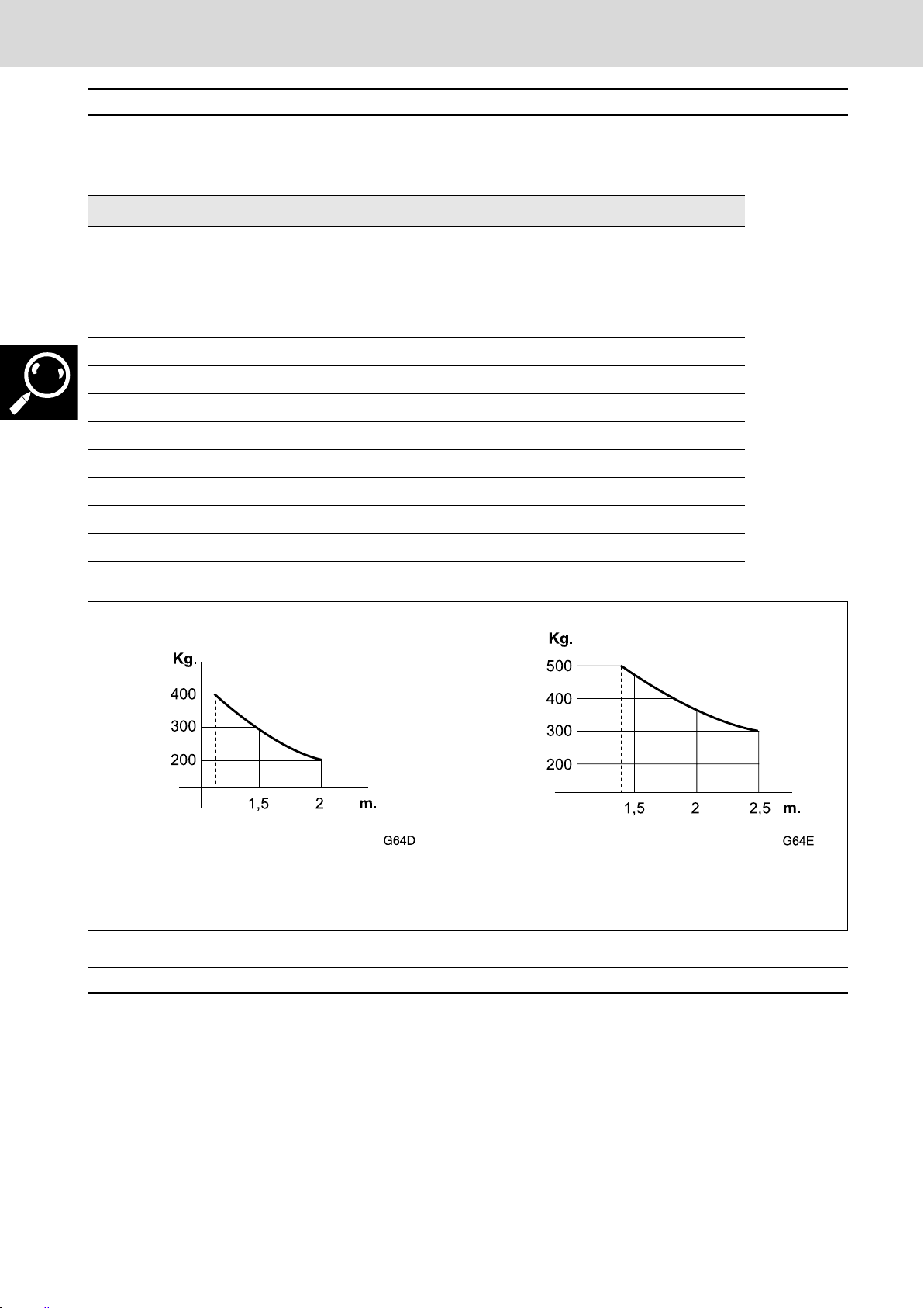
Limits on use
ARS24C AR220C
We recommend using an electrolock for leaf lengths of over 1.8m.
Values for orientation purposes. The form of the leaf and the presence of strong wind may
bring notable differences in the values of the chart.
3
Erreka Automatismos declares that the ARC
electromechanical actuator has been designed for use
in a machine or for assembly along with other elements
in order to form a machine in line with Directive 89/392
EEC and successive modifications.
The ARC electromechanical actuator allows us to carry
out installations in line with the standards EN 13241-1
and EN 12453.
DECLARATION OF CONFORMITY
The ARC electromechanical actuator complies with
safety legislation in line with the following directives
and standards:
• 73/23 EEC and successive modification 93/68 EEC
• 89/366 EEC and successive modifications 92/31 EEC
and 93/68 EEC
• UNE-EN 60335-1
28 Installation Manual
Descripcion_64 v0.0.fm - 6/4/09
 Loading...