


MACCHINA DUPLICATRICE DI CHIAVI
DAKAR EVOLUTION
MANUALE D’ISTRUZIONI
KEY CUTTING MACHINE
DAKAR EVOLUTION
INSTRUCTION MANUAL
MACHINE DUPLICATRICE
DAKAR EVOLUTION
NOTICE D’UTILISATION
DUPLIZIERMASCHINE
DAKAR EVOLUTION
BEDIENUNGSANLEITUNG
MÁQUINA DUPLICADORA
DAKAR EVOLUTION
MANUAL DE INSTRUCCIONES
NØGLEMASKINE
DAKAR EVOLUTION
BRUGSANVISNING
DAKAR EVOLUTION

ITALIANO
DAKAR
EVOLUTI0N
MANUALE D’ISTRUZIONI
MACCHINA DUPLICATRICE DI CHIAVI

ITALIANO
1.- PRESENTAZIONE E ASPETTI GENERALI
1.1 GENERALITÀ
1.2 IMBALLAGGIO E TRASPORTO
1.3 ETICHETTA IDENTIFICATIVA
2. - CARATTERISTICHE DELLA MACCHINA
2.1 TIPI DI CHIAVI
2.2 ACCESSORI
2.3 MAGAZZINO UTENSILI
2.4 CIRCUITO ELETTRICO
2.5 DATI TECNICI
2.6 ELEMENTI PRINCIPALI DELLA MACCHINA
2.7 COMPONENTI E PARTI FUNZIONALI
2.7.1 CAMBIO DI FRESA E DI TASTATORE (21)
2.7.2 BLOCCAGGIO DEL CARRELLO ALLA FINE DELLA CORSA DELL’ASSE “Y”
2.7.3 MORSETTO (6)
2.7.4 MOLLEGGIO DEL TASTATORE (11)
2.7.5 MOLLEGGIO E BLOCCAGGIO DEL CARRELLO SULL’ASSE “X“ (5 E 4)
2.7.6 LEVA DI SOSTEGNO PER CHIAVI TUBOLARI
2.7.7 VELOCITÀ DELLA FRESA (17)
2.7.8 DISPLAY-TASTIERA (1)
2.7.9 TARATURA VERTICALE DEL TASTATORE (15)
2.7.10 CONTROLLO DELLA FORZA DI DUPLICAZIONE
3.- CIFRATURA
3.1 PROCEDURA DI CIFRATURA
3.2 CIFRATURA DELLE CHIAVI
3.2.1 CHIAVI KB2, KB4 E KB5.
3.2.2 CHIAVE KC1.
3.2.3 CHIAVE SE1L
3.2.4 CHIAVI HF42P15 E YM22P15
3.2.5 CHIAVI HF40P18 E HF38P17
3.2.6 CHIAVI TUBOLARI
3.2.7 CHIAVI FC6 E FC120
3.2.8 CHIAVI TK23, TK24 E TK25
3.2.9 CHIAVE JIS4P
3.2.10 CHIAVE TB1P5
3.2.11 CHIAVE MD13R
3.2.12 CHIAVE TS14 E TS12
4.- MANUTENZIONE
4.1 SOSTITUZIONE DELLE GANASCE DEL MORSETTO
4.2 TARATURA DELLE GANASCE
4.2.1 TARATURA NORMALE
4.2.2 TARATURA DI PRECISIONE
4.3 SOSTITUZIONE DEI FUSIBILI
4.4 TENSIONAMENTO E SOSTITUZIONE DELLA CINGHIA
4.5 SOSTITUZIONE DEL MOTORE
4.6 SOSTITUZIONE DEL DISPLAY-TASTIERA
4.7 SOSTITUZIONE DELLA SCHEDA ELETTRONICA DI CONTROLLO
4.8 SOSTITUZIONE DELLA SCHEDA DI POTENZA E DEL DISGIUNTORE
5.- SICUREZZA
6.- SMALTIMENTO DEI RIFIUTI
6.1 IMBALLAGGIO
6.2 TRUCIOLI
6.3 MACCHINA
7.- TABELLA CHIAVE-FRESA-TASTATORE-INCLINAZIONE-ADATTATORE
8.- ESPLOSO
ITALIANO
1.- PRESENTAZIONE E ASPETTI GENERALI
1.1 GENERALITÀ
La macchina duplicatrice di chiavi DAKAR EVOLUTION è stata progettata tenendo conto
delle norme di sicurezza vigenti nella C.E.E.
La sicurezza del personale addetto al funzionamento di questo tipo di macchine si ottiene esclusivamente con un programma ben progettato in fatto di sicurezza personale,
eseguendo regolarmente la manutenzione e seguendo i consigli forniti, nonché con il
rispetto delle norme di sicurezza riportate in questo manuale.
Anche se l’installazione della macchina non presenta alcuna difficoltà, è preferibile non
cercare di installarla, di regolarla o di usarla senza aver letto prima questo manuale.
La macchina esce dalle nostre strutture pronta per l’uso ed è solo necessario eseguire
le operazioni di taratura degli utensili da usare.
1.2 IMBALLAGGIO E TRASPORTO
La macchina è imballata in una robusta scatola di cartone protetta con schiuma da
imballaggio, con le seguenti dimensioni:
Larghezza = 520 mm; Altezza = 650 mm; Profondità = 575 mm
Peso della macchina con l’imballaggio = 30 Kg
Durante il disimballo della macchina, ispezionare accuratamente la macchina per accertarsi che non abbia subito danni durante il trasporto.
Se venisse rilevata qualche anomalia, avvertire immediatamente il trasportatore e non
usare la macchina prima che l’agente del trasportatore esegua la relativa ispezione.
Per spostare la macchina da un posto all’altro, afferrarla dalla base e non da altre parti.
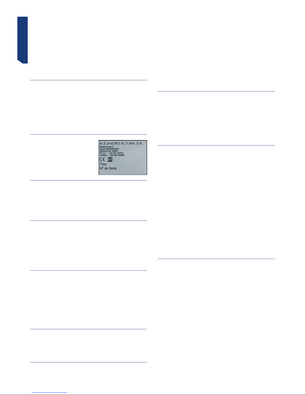
1.3 ETICHETTA IDENTIFICATIVA
La macchina duplicatrice di chiavi DAKAR EVOLUTION è munita di etichetta identificativa,
nella quale sono riportati il numero di serie, il
nome e l’indirizzo del costruttore, il marchio CE
e l’anno di fabbricazione.
2. - CARATTERISTICHE DELLA MACCHINA
La macchina DAKAR EVOLUTION è una duplicatrice molto robusta e di grande precisione, caratterizzata dalle molteplici possibilità di fissaggio consentito dal morsetto, senza
necessità di usare supporti, né adattatori.
È munita di un innovativo sistema di controllo della forza, che aumenta la precisione
della duplicazione.
2.1 TIPI DI CHIAVI
La macchina DAKAR EVOLUTION duplica, tra gli altri, i seguenti tipi di chiavi:
- Chiavi piatte
- Chiavi laser
- Chiavi tubolari
- Chiavi FC6 e FC120
- Chiavi TK23, TK24 e TK25
- Chiavi JIS4P
- Chiavi TB1P5
2.2 ACCESSORI
La macchina è fornita con una serie di accessori per l’uso e la manutenzione. Tutti questi accessori possono essere riposti nel magazzino utensili di cui dispone la macchina.
- 2 fusibili (posti nella parte inferiore del magazzino utensili)
- Chiavi a brugola da 5, da 3 e da 2,5
- 1 Chiave a brugola speciale con braccio corto da 1,5.
- 2 Lamiere di arresto punta
- 2 assi per la taratura delle ganasce.
- 2 Adattatore per la chiave tubolare CHI9T
- Frese: F-1 e F-13
- Tastatori: T-1 e T-13.
2.3 MAGAZZINO UTENSILI
La macchina dispone di un magazzino utensili, montato sulla parte superiore della macchina. È possibile estrarlo e appoggiarlo direttamente su un piano di lavoro (in tal modo
si ottiene uno spazio in più sulla parte superiore della macchina, che si può sfruttare per
depositarvi chiavi, accessori, ecc.).
2.4 CIRCUITO ELETTRICO
I componenti principali del circuito elettrico ed elettronico sono i seguenti:
1. Presa di corrente.
2. Morsettiera.
3. Interruttore a 3 posizioni.
4. Trasformatore.
5. Motore.
6. Display-tastiera.
7. Scheda di controllo.
8. Fresa.
9. Tastatore.
10. Morsetto.
11. Diodi LED di illuminazione.
12. Sensore di forza.
Vedi Fig. 2
2.5 DATI TECNICI
Motore: Monofase 400 W, 230 V - 50 Hz (Optional: Monofase 400 W, 110 V – 60 Hz)
Fresa: HSS (Optional: metallo duro)
Velocità fresa: 6.000 e 11.000 giri/min.
Morsetti: A due facce di serraggio e basculanti 0 / 45 º
Spostamento: Su tre assi con guide a rulli di precisione.
Corse utili: Asse X = 71 mm; Asse Y = 62 mm; Asse Z = 40 mm
Illuminazione: Diodi Led
Dimensioni: Larghezza = 430 mm, Profondità = 385 mm e Altezza = 485 mm
Peso: 25 Kg
2.6 ELEMENTI PRINCIPALI DELLA MACCHINA
1.- Display-tastiera.
2.- Carrello porta-morsetti (assi X – Y)
3.- Leva di azionamento dei carrelli, assi X – Y
4.- Pomello di bloccaggio del carrello porta-morsetti, asse X
5.- Manopola di azionamento del sistema di molleggio del carrello, asse X
6.- Morsetto
7.- Leva di bloccaggio della rotazione dei morsetti
8.- Pomello del morsetto
9.- Testa (asse Z)
10.- Leva di azionamento e bloccaggio della testa, asse Z
11.- Leva di molleggio del tastatore
12.- Portautensili
13.- Fresa
14.- Tastatore
15.- Manopola di taratura dell’altezza del tastatore
16.- Interruttore generale
17.- Selettore della velocità del motore (2 velocità)
18.- Led di illuminazione
19.- Protezione dai trucioli
20.- Magazzino utensili
21.- Pulsante di bloccaggio della fresa
Vedi Fig. 3
2.7 COMPONENTI E PARTI FUNZIONALI
2.7.1 CAMBIO DI FRESA E DI TASTATORE (21)
Per allentare la fresa, azionare il pulsante di bloccaggio della fresa mentre allo stesso
tempo si fa girare il portautensili con la mano.
Dopo aver estratto la fresa da cambiare, inserire la nuova fresa e stringerla nel portautensili, accertandosi che l’estremità sia a battuta all’interno del portautensili.
Il tastatore si cambia allo stesso modo della fresa. L’unica differenza da ricordare è che
la rotazione del tastatore è sempre bloccata internamente.
2.7.2 BLOCCAGGIO DEL CARRELLO ALLA FINE DELLA CORSA
DELL’ASSE “Y”
Per evitare che il carrello si sposti nella direzione “Y”, nel tempo in cui si stanno stringendo le chiavi nel morsetto del duplicatore, il carrello è munito di bloccaggio momentaneo in questa direzione.
Per azionare il bloccaggio, basta spostare il carrello fino a battuta nella direzione verso
il duplicatore.
Per disattivare questo bloccaggio, basta spostare il carrello in avanti esercitando una
leggera pressione.
2.7.3 MORSETTO (6)
Le prestazioni del morsetto della duplicatrice DAKAR EVOLUTION sono superiori a quelle di una macchina normalmente reperibile sul mercato, in quanto dispone di due facce
di serraggio indipendenti. Inoltre, i morsetti si possono bloccare in qualsiasi posizione
di rotazione tra 45º 0º -45º.
ITALIANO
2.7.4 MOLLEGGIO DEL TASTATORE (11)
Vi sono due modi diversi per usare il tastatore, a seconda della lavorazione da eseguire:
- Tastatore con molleggio. Il molleggio del tastatore si usa esclusivamente per
la cifratura delle chiavi piatte.
-Tastatore bloccato. Il tastatore bloccato si usa per eseguire operazioni di
duplicazione con avanzamento del carrello. In genere, per la cifratura
delle chiavi laser.
Per attivare o disattivare il molleggio del tastatore, basta fare ruotare di 180º (mezzo
giro) la leva di molleggio del tastatore.
Quando si attiva il molleggio del tastatore, la punta del tastatore si situa leggermente
al di sotto della posizione di taratura rispetto alla fresa. Questa posizione del tastatore
consente di inserirlo delicatamente nel foro della chiave originale, prima che la fresa
cominci la fresatura della chiave da duplicare. In tal modo si evitano vibrazioni e spostamenti bruschi del carrello.
Per controllare in qualsiasi momento lo stato del tastatore (con molleggio o bloccato),
sul display-tastiera della macchina è presente un indicatore che offre tali informazioni.
Se la spia è accesa, il molleggio è attivato. Se invece la spia è spenta, il tastatore è
bloccato.
2.7.5 MOLLEGGIO E BLOCCAGGIO DEL CARRELLO SULL’ASSE “X“ (5 E 4)
Il sistema di molleggio del carrello sull’asse “X” è consigliato per eseguire le fresature
laterali delle chiavi laser.
Il bloccaggio del carrello sull’asse “X“ è consigliato per eseguire fresature o punti in
linea retta.
2.7.6 LEVA DI SOSTEGNO PER CHIAVI TUBOLARI
La macchina duplicatrice di chiavi DAKAR EVOLUTION è munita, sulla parte superiore
del lato sinistro, di una leva che serve a rendere più comoda la duplicazione delle chiavi
tubolari, laser, ecc., in quanto dispone di un punto di sostegno per la mano che aziona
la leva di traslazione dei carrelli.
2.7.7 VELOCITÀ DELLA FRESA (17)
La macchina dispone di un selettore della velocità, situato sul lato destro, che consente
di impostare la velocità di rotazione della fresa. In linea di massima, si può dire che la
velocità di rotazione dipende dal materiale della fresa:
- Posizione I: per lavorare con fresa di HSS (6.000 giri/min.)
- Posizione II: per lavorare con fresa di METALLO DURO (11.000 giri/min.)
- Posizione O: fresa ferma.
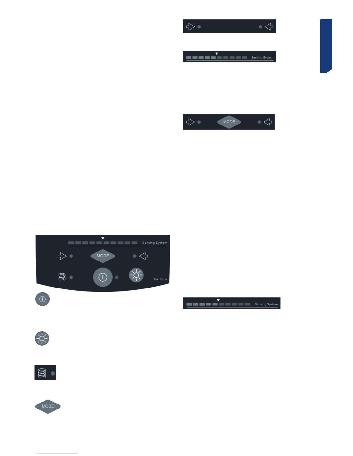
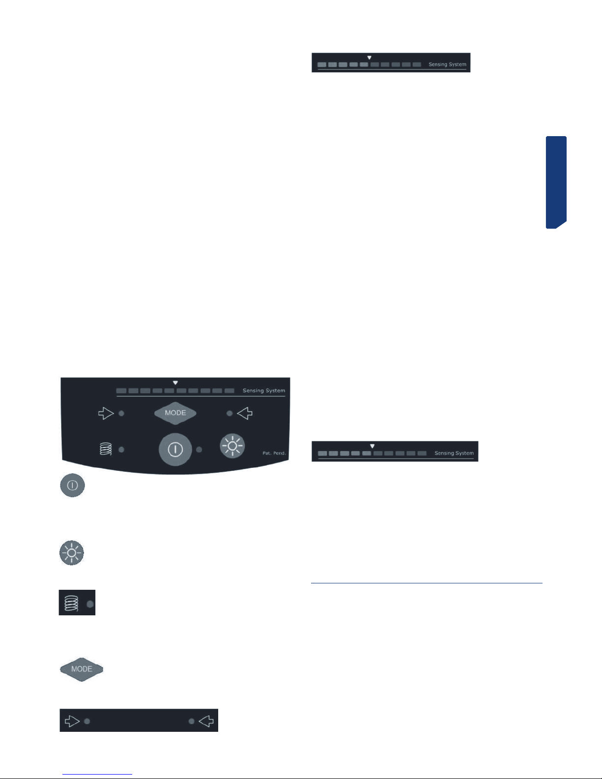
2.7.8 DISPLAY-TASTIERA (1)
Tasto ON-OFF.
Premendolo, le funzioni del display-tastiera passano allo stato ATTIVATO. Accanto al
tasto compare una spia verde.
Premendolo di nuovo, il display-tastiera passa allo stato di “STAND-BY”. Accanto al
tasto compare una spia rossa.
Tasto ILLUMINAZIONE.
Premendolo, si accendono i diodi d’illuminazione (se sono spenti) oppure si spengono
se sono accesi.
Questo tasto funziona indipendentemente dallo stato del tasto “ON-OFF”.
Indicatore MOLLEGGIO.
Se è accesa la spia blu, indica che il tastatore si trova nello stato di MOLLEGGIO ATTIVATO.
Se la spia blu è spenta, indica che il tastatore è BLOCCATO (molleggio disattivato).
Tasto MODE.
Questo tasto serve per attivare-disattivare il funzionamento del sistema di taratura
verticale del tastatore.
Indicatori di TARATURA DEL TASTATORE.
La spia a sinistra si accende quando il tastatore sta toccando la chiave.
La spia a destra si accende quando la fresa sta toccando la chiave.
Indicatore visivo della FORZA.
Indica la forza ottimale da applicare durante la duplicazione.
NOTA: il sistema di controllo della forza, oltre all’indicatore visivo, è anche munito di un
indicatore sonoro che avverte con un segnale acustico quando è stata raggiunta la forza
ottimale di duplicazione. Questo indicatore sonoro si può attivare-disattivare premendo
allo stesso tempo i tasti MODE e ON-OFF.
2.7.9 TARATURA VERTICALE DEL TASTATORE (15)
Per ogni cambio di fresa-tastatore, occorre eseguire la taratura verticale del tastatore.
Per potere usare il sistema elettronico di taratura verticale del tastatore, è necessario
che il display-tastiera sia attivato (quando lo è, si accende una spia verde accanto al
tasto ON-OFF).
Quando il display-tastiera è attivato, è possibile attivare-disattivare il sistema elettronico di taratura verticale del tastatore premendo il tasto MODE.
Per effettuare la taratura verticale del tastatore, procedere come segue:
• Serrare la fresa e il tastatore nei relativi portautensili. Accertarsi che siano
serrati correttamente, a battuta in alto.
• Serrare due chiavi uguali nei morsetti della macchina.
• Disattivare il molleggio del tastatore (tastatore bloccato).
• Abbassare la testa, fino ad appoggiare la fresa e il tastatore sulle chiavi situate
nei morsetti. Si possono quindi verificare tre situazioni:
SPIA BLU A SINISTRA. Se si accende solo la spia a sinistra, indica che il
tastatore sta toccando la chiave, ma la fresa no. Perciò occorre girare la
manopola di taratura del tastatore a sinistra, fino all’accensione delle due spie
di taratura.
SPIA BLU A DESTRA. Se si accende solo la spia a sinistra, indica che la fresa
sta toccando la chiave, ma il tastatore no. Perciò occorre girare la manopola
di taratura del tastatore a destra, fino all’accensione delle due spie di taratura.
SPIE BLU A SINISTRA E A DESTRA. Indicano che sia la fresa che il tastatore
stanno toccando le rispettive chiavi. Ciò significa che l’altezza del tastatore
è tarata.
NOTA BENE: Quando si esegue la taratura dell’altezza del tastatore, occorre tenere
conto del tipo di chiave da duplicare. Se si tratta di una chiave LASER, bisogna applicare
poca forza sulla leva di azionamento della testa (non si deve accendere alcun segmento
dell’indicatore visivo della forza). Se invece si tratta di una chiave PIATTA, si devono
accendere le due spie blu della taratura, mentre l’indicatore della forza indica la forza
ideale per la duplicazione delle chiavi piatte (per questo bisogna esercitare una lieve
forza sulla leva di azionamento della testa).
2.7.10 CONTROLLO DELLA FORZA DI DUPLICAZIONE
La macchina DAKAR EVOLUTION dispone di un rivoluzionario sistema di controllo di
forza di duplicazione. Si tratta di un sistema brevettato, che per duplicare chiavi PIATTE,
indica la forza ottimale da applicare sulla leva di azionamento della testa. Per questo,
vi sono due indicatori:
Indicatore visivo. La forza ottimale di duplicazione si raggiunge quando i segmenti luminosi raggiungono la freccia bianca.
Indicatore sonoro. Quando i segmenti luminosi raggiungono la freccia bianca,
la macchina emette un segnale acustico. Questo indicatore sonoro si può attivaredisattivare premendo allo stesso tempo i tasti MODE e ON-OFF.
Questo sistema di controllo della forza di duplicazione consente di ottenere chiavi PIATTE con una grande precisione. I fori della chiave si duplicano esattamente con la stessa
forza con la quale è stata tarata l’altezza del tastatore. In tal modo si ottiene la massima
precisione nella duplicazione delle chiavi PIATTE.
3.- CIFRATURA
3.1 PROCEDURA DI CIFRATURA
• Accendere la macchina azionando l’interruttore generale situato nella parte posteriore destra della macchina.
• Per migliorare la visibilità della zona di lavoro, attivare l’illuminazione azionando
l’interruttore situato sul display-tastiera.

ITALIANO
• Consultando la tabella riportata in questo manuale, selezionare la fresa e il tastatore necessari per la cifratura della chiave.
• Cambiare la fresa e il tastatore.
• Bloccare momentaneamente il carrello alla fine della corsa dell’asse “Y”.
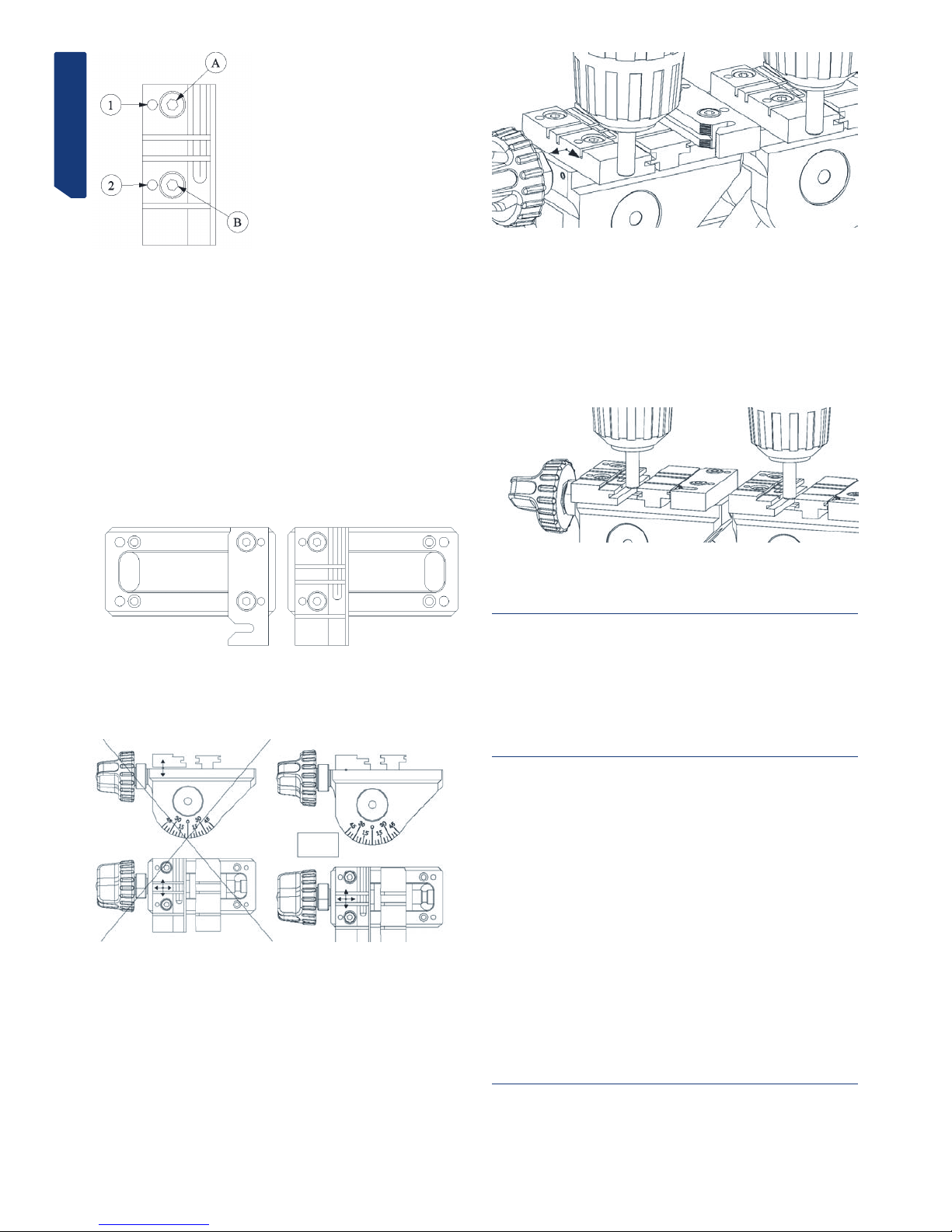
• Serrare la chiave originale a sinistra del morsetto e la chiave da cifrare a destra.
Per serrare le chiavi, bisogna tenere presente i seguenti particolari:
-BATTUTA DELLA CHIAVE. Può trattarsi di una chiave “a battuta sul collo” (Fig. 4.A)
oppure “a battuta sulla punta” (Fig. 4.B).
-ADATTATORE. In qualche modello di chiave molto specifico, può essere necessario l’uso di un adattatore.
-INCLINAZIONE. Alcune chiavi hanno le punzonature inclinate, pertanto è necessario girare il morsetto.
• Eseguire la taratura verticale del tastatore.
• Attivare i sistemi che semplificano la duplicazione:
-TASTATORE: attivare o disattivare il molleggio del tastatore, in base al tipo di
chiave da cifrare.
-CARRELLO: in base al modello di chiave, può essere interessante attivare il molleggio del carrello o il bloccaggio del carrello nella direzione “X”.
-SOSTEGNO: in base al modello di chiave, può essere conveniente usare la leva di
sostegno per chiavi tubolari.
• Mettere in funzione la rotazione della fresa, dopo aver impostato una delle due
velocità disponibili.
• Eseguire la cifratura della chiave. Se la chiave è piatta, servirsi del sistema di
“controllo della forza di duplicazione”.
3.2 CIFRATURA DELLE CHIAVI
3.2.1 CHIAVI KB2, KB4 E KB5.
• A seconda del modello di chiave da duplicare, si usa una coppia fresa-tastatore
diversa. Consultare la tabella.
• Il serraggio della chiave nel morsetto si effettua “a battuta sul collo”.
• A seconda del modello di chiave da duplicare, è necessario girare i morsetti con
l’angolazione richiesta. Consultare la tabella.
• È necessario attivare il molleggio del tastatore.
• Per aumentare la precisione della cifratura, usare il sistema di “controllo della
forza di duplicazione”.
• NOTA: le punzonature della chiave KB4 devono essere sempre nella parte più bassa del morsetto.
• NOTA: le punzonature della chiave KB2 devono essere sempre nella parte più alta
del morsetto.
Vedi Fig. 5
3.2.2 CHIAVE KC1.
• Usare la fresa-tastatore: F-1 / P-1.
• Il serraggio della chiave nel morsetto si effettua “a battuta sul collo”, ma inserendo la chiave dalla parte posteriore.
• È necessario posizionare i morsetti con un’inclinazione di 5º.
• È necessario attivare il molleggio del tastatore.
• Per aumentare la precisione della cifratura, usare il sistema di “controllo della
forza di duplicazione”.
• NOTA: le punzonature della chiave KC1 devono essere sempre nella parte più alta
del morsetto.
• NOTA: per la duplicazione delle punzonature laterali, bisogna usare il relativo
adattatore.
Vedi Fig. 6
3.2.3 CHIAVE SE1L
• Usare la fresa-tastatore: F-3 / P-3.
• Il serraggio della chiave nel morsetto si effettua “a battuta sul collo”.
• È necessario bloccare il tastatore (disattivare il molleggio).
• NOTA: dopo aver eseguito la taratura verticale del tastatore, bisogna abbassare
molto leggermente il tastatore, girando la manopola di regolazione 5 punti verso destra.
Quindi occorre inserire il tastatore nella scanalatura della mappa e bloccare la testa della macchina. Infine bisogna solllevare leggermente il tastatore, per evitare che trascini
la chiave.
• NOTA: effettuare l’attacco dal centro del canale senza toccare i lati e, nella seconda passata, cominciare dal lato destro e uscire da quello sinistro, senza esercitare
alcuna pressione (esclusivamente appoggiando leggermente il tastatore).
• NOTA: per la duplicazione delle punzonature laterali, usare la fresa-tastatore F-1
/ P-1, “a battuta sul collo”. Attivare il molleggio del tastatore e usare il sistema di
“controllo della forza di duplicazione”.
Vedi Fig. 7
3.2.4 CHIAVI HF42P15 E YM22P15
• Usare la fresa-tastatore: F-11 / P-11.
• Il serraggio della chiave nel morsetto si effettua “a battuta sulla punta”.
• È necessario bloccare il tastatore (disattivare il molleggio).
• NOTA: dopo aver eseguito la taratura verticale del tastatore, bisogna abbassare
molto leggermente il tastatore, girando la manopola di regolazione 5 punti verso destra.
Quindi occorre inserire il tastatore nella scanalatura della mappa e bloccare la testa della macchina. Infine bisogna solllevare leggermente il tastatore, per evitare che trascini
la chiave.
• NOTA: è consigliabile usare il sistema di molleggio del carrello.
• NOTA: si consiglia di eseguire una passata di sbozzatura e quindi un’altra passata
di finitura seguendo tutto il profilo del disegno della chiave. Si lavora in senso discendente (dalla punta della chiave verso la testa).
Vedi Fig. 8
3.2.5 CHIAVI HF40P18 E HF38P17
• Usare la fresa-tastatore: F-11 / P-11.
• Il serraggio della chiave nel morsetto si esegue utilizzando l’adattatore AD-MM2.
-Posizionare l’adattatore sul morsetto, “a battuta sulla punta”.
-Inserire la chiave nell’adattatore.
-Mentre si effettua il serraggio dell’adattatore nel morsetto, la chiave resta fissata
nell’adattatore.
• È necessario bloccare il tastatore (disattivare il molleggio).
• NOTA: dopo aver eseguito la taratura verticale del tastatore, bisogna abbassare
molto leggermente il tastatore, girando la manopola di regolazione 5 punti verso destra.
Quindi occorre inserire il tastatore nella scanalatura della mappa e bloccare la testa della macchina. Infine bisogna solllevare leggermente il tastatore, per evitare che trascini
la chiave.
• NOTA: è consigliabile usare il sistema di molleggio del carrello.
Vedi Fig. 9
3.2.6 CHIAVI TUBOLARI
• Usare la fresa-tastatore: F-8 / P-8.
• Serrare la chiave nella “V” del morsetto.
• È necessario attivare il molleggio del tastatore.
• L’operazione d’intaglio è più comoda se si appoggia la mano che aziona la leva di
azionamento del carrello sulla leva di sostegno per chiavi tubolari.
Vedi Fig. 10
3.2.7 CHIAVI FC6 E FC120
• Usare la fresa-tastatore: F-11 / P-11.
• Serrare la chiave nel morsetto, appoggiandola sul fondo e spingendola verso la
faccia anteriore del morsetto.
• È necessario bloccare il tastatore (disattivare il molleggio).
• Bloccare la testa della macchina a un’altezza tale che la fresa passi sul morsetto,
ma senza strisciarlo.
• Eseguire l’intaglio sui due lati superiori.
• Girare le chiavi facendo attenzione a togliere le bave, per assicurare il corretto
posizionamento e serraggio della chiave, ed eseguire l’intaglio sugli altri due lati della
chiave.
Vedi Fig. 11
3.2.8 CHIAVI TK23, TK24 E TK25
• Usare la fresa-tastatore: F-15 / P-15.
• Serrare nel morsetto due chiavi grezze ed eseguire sulle stesse la taratura verticale del tastatore.
• Serrare la chiave originale con la dentatura verso l’alto (come indicato nel disegno).
• È necessario bloccare il tastatore (disattivare il molleggio).
• Inserire il tastatore con precisione in uno dei punti e bloccare la testa della macchina a quell’altezza.
• Eseguire l’intaglio.
Vedi Fig. 12
3.2.9 CHIAVE JIS4P
• Usare la fresa-tastatore: F-11 / P-11.
• Il serraggio della chiave nel morsetto si esegue utilizzando l’adattatore AD-MJ.
-Posizionare l’adattatore sul morsetto, “a battuta sulla punta”.
-Inserire la chiave nell’adattatore, “a battuta sul collo” contro la piastra che gira.
In questa posizione, serrare la chiave nel relativo adattatore.
• È necessario bloccare il tastatore (disattivare il molleggio).
Vedi Fig. 13
3.2.10 CHIAVE TB1P5
• Usare la fresa-tastatore F-22 / P-22.
• Il serraggio della chiave nel morsetto si esegue utilizzando il relativo adattatore.
- Posizionare e serrare gli adattatori sul morsetto.
- Nel posizionare la chiave, fare attenzione che sia ben livellata, per eseguire i due
intagli identici.

ITALIANO
• È necessario bloccare il tastatore (disattivare il molleggio).
• Inserire il tastatore nella scanalatura di una lettera. Bloccare la testa della macchina e abbassare leggermente il tastatore per evitare che urti contro l’adattatore.
• Eseguire l’intaglio.
Vedi Fig. 14
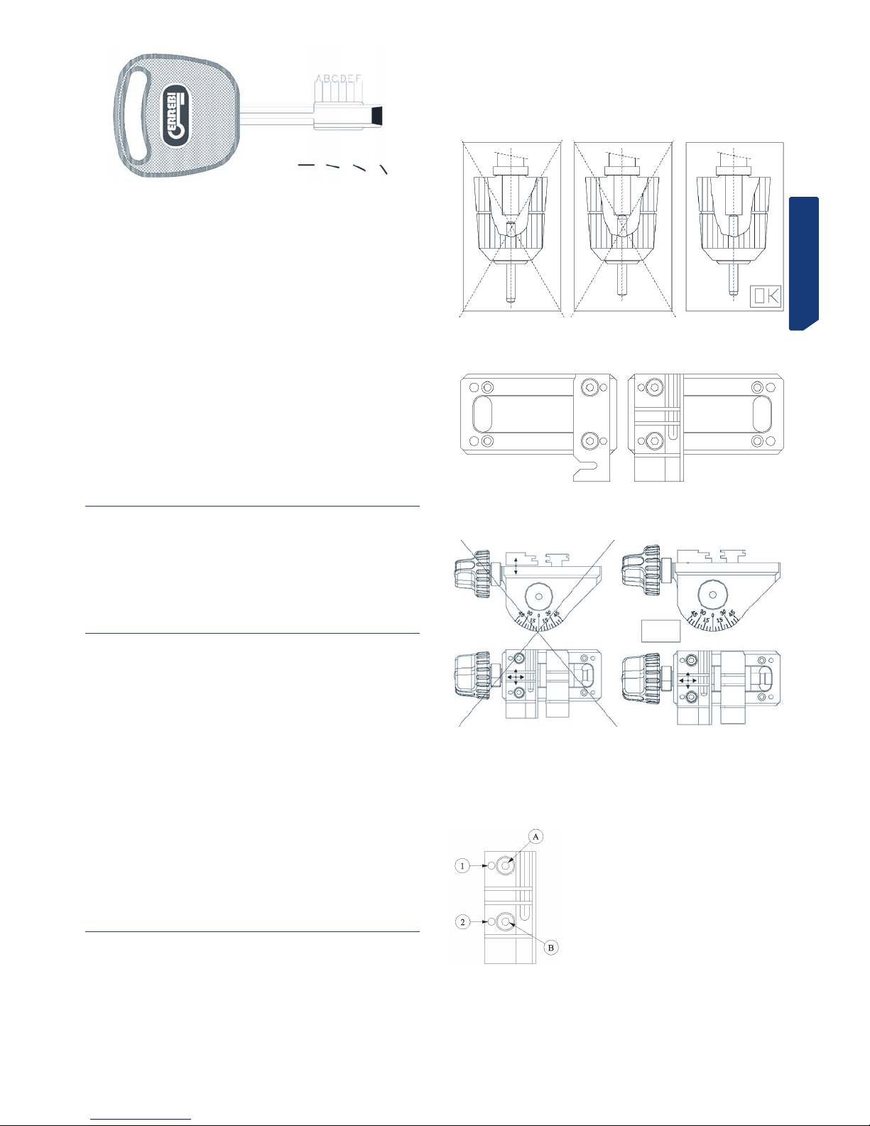
Lettura del codice della chiave originale
• La chiave originale ha 6 posizioni di duplicazione, definite tramite le lettere A, B, C,
D, E ed F, come illustrato nella figura nella figura seguente
• In ogni posizione della chiave, vi sono le seguenti 4 diverse combinazioni possibili
(impostate tramite numeri):
1 2 3 4
• L’“altezza” n. 1 indica che non si deve duplicare. La posizione n. 2 indica che c’è un
piccola sfacciatura nella chiave e quando la stessa è leggermente più grande corrisponde all’altezza n. 3. L’altezza n. 4 è la maggiore sfacciatura della chiave.
• Si prende quindi la chiave e si segnano le combinazioni di ciascuna delle 6 posizioni, come indicato nel seguente esempio:
POSIZIONE A B C D E F
COMBINAZIONE 3 4 1 2 4 2
NOTA: La serie di numeri della combinazione è il codice della chiave.
3.2.11 CHIAVE MD13R
• Posizione speciale nel morsetto. Vedi figura.
Vedi fig. 15
3.2.12 CHIAVE TS14 E TS12
• Posizione speciale nel morsetto. La chiave TS14 si stringe come indicato nel disegno.
• La chiave TS12 ha la particolarità che per lavorare il lato sinistro si stringe come la
TS14, mentre per lavorare il lato destro bisogna serrare la chiave dalla parte posteriore
del morsetto (come nel caso della MD13R).
Vedi Fig. 16
4.- MANUTENZIONE
Per l’esecuzione di qualsiasi operazione di manutenzione, è necessario soddisfare i
seguenti requisiti:
1. Non eseguire mai alcuna operazione con la macchina in funzione.
2. Disinserire il cavo dalla connessione elettrica.
3. Seguire rigorosamente le indicazioni del manuale.
4. Usare esclusivamente pezzi di ricambio originali.
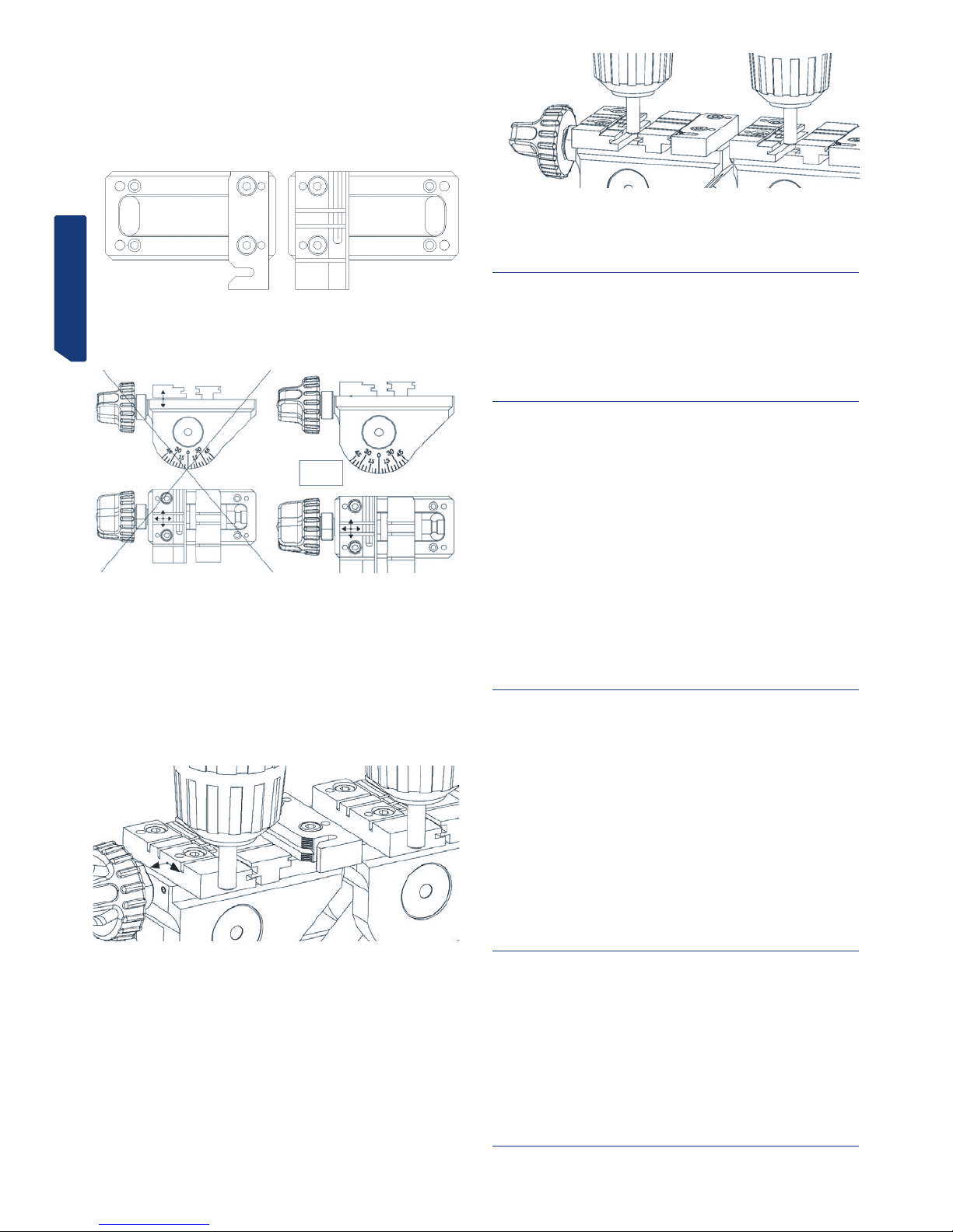
4.1 SOSTITUZIONE DELLE GANASCE DEL MORSETTO
Il morsetto della macchina DAKAR EVOLUTION dispone di tre coppie di ganasce (ganascia fissa sinistra, ganascia fissa destra e ganascia mobile). In caso di danneggiamento
di una ganascia, è possibile sostituirla singolarmente con una nuova.
Per sostituire la “ganascia fissa sinistra” (A) o la “ganascia fissa destra” (B), basta
svitare le due viti di fissaggio ed estrarle tirando verso l’alto. Per montare le ganasce
nuove, procedere in senso inverso.
Per sostituire la “ganascia mobile” (C), procedere come segue:
1) Servendosi di un cutter o simile, estrarre il coperchio nero di plastica della leva del
morsetto.
2) Mentre si blocca il controdado con una chiave fissa da 14, inserire una chiave a
brugola da 5 nel foro che è rimasto scoperto nella leva del morsetto e svitarlo.
3) Posizionare il morsetto con un’inclinazione di 45º, e girando manualmente il mandrino, estrarlo da uno dei lati. Una volta estratto il mandrino, la ganascia mobile resta
libera e si può rimuovere.
4) Per montare la nuova ganascia mobile, procedere in senso inverso.
NOTA BENE: quando si sostituisce la ganascia fissa sinistra o quella fissa destra,
eseguire sempre la taratura della coppia di ganasce che sono state sostituite. Se invece
si sostituisce la ganascia mobile, non è necessaria nessuna operazione di taratura delle
ganasce.
Vedi Fig. 17
4.2 TARATURA DELLE GANASCE
Quando si sostituisce la ganascia fissa sinistra o quella fissa destra, bisogna eseguire sempre la taratura della coppia di ganasce che sono state sostituite. Se invece si
sostituisce la ganascia mobile, non è necessaria nessuna operazione di taratura delle
ganasce.
Vi sono due modi diversi per eseguire la taratura delle ganasce:
Taratura NORMALE
Taratura di PRECISIONE
4.2.1 TARATURA NORMALE
Si tratta di una regolazione semplice e veloce, con la quale si ottiene una taratura
accettabile per poter duplicare chiavi con una certa precisione.
Per eseguire questa taratura, procedere come segue:
1) Serrare i due assi di taratura nei relativi portautensili, in modo tale che siano a
battuta all’interno del portautensili e che la parte conica degli stessi sia all’esterno.
2) La ganascia fissa sinistra sul lato destro del morsetto e quella fissa destra sul
lato sinistro non si possono tarare dato che sono posizionate tramite spinotti. Perciò
bisogna montarle guidandole sui loro spinotti e quindi fissarle con le relative viti.
3) Sapendo che in ogni coppia di ganasce ce n’è una la cui posizione è fissa, occorre
tarare l’altra ganascia rispetto a quest’ultima.
4) Inserire le viti nella ganascia da tarare, ma senza stringerle, in modo tale la ganascia si possa muovere con la mano, ma che a sua volta non abbia la possibilità di
sollevarsi rispetto alla superficie sulla quale è appoggiata.
5) Procedere alla taratura della ganascia:
5.1) Inserire l’asse di taratura del tastatore nel foro N. 1 della ganascia.
5.2) Fare coincidere l’asse di taratura della fresa nel foro N. 1 dell’altra ganascia.
5.3) Sollevare la testa ed eseguire la stessa operazione, ma nel foro N. 2 delle ganasce.
5.4) Ripetere l’operazione descritta al punto precedente tante volte quante sia necessario, fino a fare entrare gli assi di taratura dolcemente e senza forzare sia nel foro
N. 1 che in quello N. 2.
ITALIANO
5.5) Con i due assi di taratura inseriti nei fori N. 1, bloccare la testa e avvitare leggermente la vite B.
5.6) Con i due assi di taratura inseriti nei fori N. 2, bloccare la testa e avvitare leggermente la vite A.
5.7) Ripetere l’operazione descritta al punto precedente, ma avvitando definitivamente
le viti A e B.
5.8) Una volta conclusa la taratura, con una chiave a brugola speciale da 1,5 con il
braccio corto, stringere le due viti prigioniere situate tra la leva del morsetto e la ganascia appena tarata. In tal modo, si assicura una maggiore saldezza del fissaggio della
ganascia appena tarata.
4.2.2 TARATURA DI PRECISIONE
Si tratta di una regolazione che richiede di certa perizia, con la quale si ottiene una
taratura molto PRECISA delle ganasce sostituite.
Per eseguire questa taratura, procedere come segue:
1) La ganascia fissa sinistra sul lato destro del morsetto e quella fissa destra sul
lato sinistro non si possono tarare dato che sono posizionate tramite spinotti. Perciò
bisogna montarle guidandole sui loro spinotti e quindi fissarle con le relative viti.
2) Sapendo che in ogni coppia di ganasce ce n’è una la cui posizione è fissa, occorre
tarare l’altra ganascia rispetto a quest’ultima.
3) Inserire le viti nella ganascia da tarare, ma senza stringerle, in modo tale la ganascia si possa muovere con la mano, ma che a sua volta non abbia la possibilità di
sollevarsi rispetto alla superficie sulla quale è appoggiata.
4) Con la chiave a brugola speciale da 1,5 con braccio corto, svitare di circa un giro le
due viti prigioniere di taratura della ganascia (sono le due viti prigioniere situate tra la
leva del morsetto e la ganascia da tarare).
5) Quindi montare qualsiasi coppia di fresa-tastatore nei relativi portautensili, ma al
contrario (con le punte di taglio rivolte verso l’interno del portautensili. Abbassare la
testa della macchina e bloccarla a un’altezza in cui gli utensili possono toccare i lati
della ganascia.
6) Attivare il sistema elettronico di taratura verticale del tastatore.
7) Appoggiare l’estremità della ganascia fissa contro il lato dell’utensile. Spostare
manualmente la ganascia da tarare nella direzione della leva del morsetto e, mantenendo la pressione sulla ganascia in quella direzione, spostarla frontalmente fino a
toccare lateralmente il relativo utensile. In questa posizione, stringere leggermente le
viti di serraggio della ganascia. Quando gli utensili stanno toccando le relative ganasce
si accendono le spie del sistema elettronico di taratura verticale del tastatore.
8) Separare quindi la ganascia mobile da quella da tarare, girando la leva del morsetto.
9) Posizionare l’utensile allineato con una delle viti di serraggio della pinza e, in questa posizione, appoggiare l’utensile contro la ganascia fissa. In questo momento, esercitando sempre una pressione molto leggera tra l’utensile e la ganascia fissa, stringere
molto lentamente la vite prigioniera allineata con l’utensile e con la vite della ganascia.
Ad un certo punto si accende la seconda spia del sistema elettronico di taratura verticale del tastatore. A questo punto smettere di stringere la vite prigioniera.
10) Posizionare l’utensile allineato con l’altra vite di serraggio della ganascia e ripetere la stessa operazione.
11) Verificare che le ganasce siano state tarate in queste due posizioni (di fronte alle
visti di fissaggio) e, se necessario, ritoccare leggermente la posizione della ganascia
stringendo molto leggermente la relativa vite prigioniera.
12) Una volta eseguita la taratura, stringere a fondo le due viti di fissaggio della ganascia.
13) Infine, stringere un po’ le due viti prigioniere di taratura della ganascia. In tal
modo, si assicura una maggiore saldezza del fissaggio della ganascia appena tarata.
4.3 SOSTITUZIONE DEI FUSIBILI
Se la macchina non si mette in funzione quando si azionano gli interruttori di start, è
necessario verificare i fusibili. Per eseguire questa operazione, procedere come segue:
1) Spegnere la macchina azionando l’interruttore generale e disinserire il cavo di alimentazione.
2) Estrarre il portafusibili che si trova sotto l’interruttore generale.
3) Verificare (usando un tester) se si è fuso qualche fusibile e quindi sostituirlo con un
altro dello stesso tipo e valore.
4.4 TENSIONAMENTO E SOSTITUZIONE DELLA CINGHIA
Per controllare il tensionamento della cinghia o per sostituirla, procedere come segue:
1) Spegnere la macchina azionando l’interruttore generale e disinserire il cavo di alimentazione.
2) Svitare le 4 viti (5) che fissano la protezione della testa ed estrarla. Le viti si trovano sul lato destro, su quello sinistro, nella parte superiore e in quella posteriore. Per
poter estrarre la protezione della testa, prima è necessario premere fino in fondo il
pulsante di bloccaggio della fresa (E).
3) Allentare, ma non rimuovere, le 4 viti (6) che fissano il motore.
4) Allentare, ma non rimuovere, i 2 dadi con controdado (7).
Tensionamento: Girando le due viti di tensionamento (8), si verifica lo spostamento del motore verso la parte posteriore della macchina. Quando si osserva che la
cinghia è tesa correttamente, stringere di nuovo i due dadi con controdado (7) e le viti
(6) che fissano il motore.
Sostituzione: Allentare, ma senza rimuovere, le 2 viti di tensionamento della
cinghia (8). Estrarre la cinghia logora e sostituirla con una nuova. Girando le due viti di
tensionamento (8), si verifica lo spostamento del motore verso la parte posteriore della
macchina. Quando si osserva che la cinghia è tesa correttamente, stringere di nuovo i
due dadi con controdado (7) e le viti (6) che fissano il motore.
5) Rimettere a posto e serrare la protezione della testa.
Vedi Fig. 18
4.5 SOSTITUZIONE DEL MOTORE
Per eseguire questa operazione, procedere come segue:
1) Spegnere la macchina azionando l’interruttore generale e disinserire il cavo di alimentazione.

ITALIANO
2) Svitare le 4 viti (5) che fissano la protezione della testa ed estrarla. Le viti si trovano sul lato destro, su quello sinistro, nella parte superiore e in quella posteriore. Per
poter estrarre la protezione della testa, prima è necessario premere fino in fondo il
pulsante di bloccaggio della fresa (E).
3) Svitare le 6 viti (9) che fissano la protezione del motore (F) ed estrarla.
4) Estrarre la cinghia (G).
5) Disinserire i cavi di alimentazione che arrivano al motore.
6) Svitare le 4 viti (6) che fissano il motore.
7) Estrarre il motore.
8) Dalla parte inferiore del motore, con un cacciavite piatto, bloccare l’asse del motore e girare manualmente la puleggia (H) fino ad estrarla (la filettatura è a sinistra).
9) Svitare le 4 viti (10) che fissano la lamiera di supporto del motore ed estrarla.
10) Per montare il nuovo motore, eseguire le stesse operazioni ma in senso inverso.
Vedi Fig. 19
4.6 SOSTITUZIONE DEL DISPLAY-TASTIERA
Per eseguire questa operazione, procedere come segue:
1) Spegnere la macchina azionando l’interruttore generale e disinserire il cavo di alimentazione.
2) Svitare le 4 viti (5) che fissano la protezione della testa ed estrarla. Le viti si trovano sul lato destro, su quello sinistro, nella parte superiore e in quella posteriore. Per
poter estrarre la protezione della testa, prima è necessario premere fino in fondo il
pulsante di bloccaggio della fresa (E).
3) Disinserire il cavo piatto che collega il display-tastiera (K) alla scheda elettronica
di controllo.
4) Staccare il vecchio display-tastiera (K) dalla protezione della testa ed estrarlo.
5) Per montare il nuovo display-tastiera, effettuare le stesse operazioni ma in senso
inverso.
Vedi Fig. 20
4.7 SOSTITUZIONE DELLA SCHEDA ELETTRONICA DI
CONTROLLO
Per eseguire questa operazione, procedere come segue:
1) Spegnere la macchina azionando l’interruttore generale e disinserire il cavo di alimentazione.
2) Svitare le 4 viti (5) che fissano la protezione della testa ed estrarla. Le viti si trovano sul lato destro, su quello sinistro, nella parte superiore e in quella posteriore. Per
poter estrarre la protezione della testa, prima è necessario premere fino in fondo il
pulsante di bloccaggio della fresa (E).
3) Disinserire il connettore principale dalla scheda elettronica di controllo (Nella)
4) Disinserire il cavo piatto che collega il display-tastiera alla scheda elettronica di
controllo (L).
5) Svitare le 3 viti (11) che fissano la scheda elettronica di controllo (Nella) alla protezione della testa ed estrarla.
6) Per montare la nuova scheda elettronica di controllo, eseguire le stesse operazioni
ma in senso inverso.
Vedi Fig. 21
4.8 SOSTITUZIONE DELLA SCHEDA DI POTENZA E DEL
DISGIUNTORE
Per eseguire questa operazione, procedere come segue:
1) Spegnere la macchina azionando l’interruttore generale e disinserire il cavo di alimentazione.
2) Svitare i 4 piedini (P) della macchina ed estrarli.
3) Svitare le 5 viti (12) che fissano la lamiera di protezione inferiore e rimuoverla.
4) Disinserire tutti i cavi dalla scheda che si desidera sostituire, dopo aver preso nota
della posizione di ogni cavo.
5) Per liberare la scheda di potenza (M) o il disgiuntore (N), basta premere sulle linguette dei 4 fissaggi e tirare la scheda verso l’alto.
6) Per montare la nuova scheda di potenza o il nuovo disgiuntore, eseguire le stesse
operazioni ma in senso inverso.
Vedi Fig. 22
5.- SICUREZZA
Per tutelare la propria sicurezza, si consiglia di rispettare le seguenti indicazioni:
• Non cercare di avviare o intervenire sulla macchina fino alla completa lettura e
comprensione di tutte le procedure di sicurezza, le istruzioni per l’installazione, la guida
dell’operatore e le procedure di manutenzione.
• Disinserire sempre l’alimentazione elettrica prima di eseguire qualsiasi intervento
di pulizia o di manutenzione.
• Mantenere sempre puliti la macchina e la postazione di lavoro.
• Lavorare con le mani asciutte.
• Usare sempre occhiali protettivi., anche se la macchina è munita di protezioni.
• Accertarsi che la macchina disponga di messa a terra.
Si consiglia di lavorare con la macchina a un’altezza che risulti comoda:
• è meglio lavorare seduti su una sedia. Regolare l’altezza della sedia finché gli occhi
dell’operatore sono all’altezza della parte più alta della macchina.
• Se si lavora in piedi, a seconda della altezza dell’operatore è consigliabile sistemare una pedana tra il piano di lavoro e la macchina, in modo tale che gli occhi
dell’operatore siano all’altezza della parte più alta della macchina.
6.- SMALTIMENTO DEI RIFIUTI
Per rifiuti si intende qualsiasi sostanza o oggetto proveniente da attività umane o da
cicli naturali che sia destinato allo smaltimento.
6.1 IMBALLAGGIO
• Dato che l’imballaggio nel quale è consegnata la macchina DAKAR EVOLUTION è
di cartone, può essere riciclato come tale.
• Si deve smaltire negli appositi cassonetti per la carta e il cartone.
• Le protezioni della macchina all’interno della scatola di cartone sono di materiale
polimerico equiparabile ai rifiuti solidi urbani e perciò possono essere smaltite presso
le normali strutture di smaltimento dei rifiuti.
6.2 TRUCIOLI
• I residui provenienti dalla duplicazione delle chiavi sono rifiuti speciali, ma sono
equiparati ai rifiuti solidi urbani, come ad esempio le pagliette metalliche.
• Questi rifiuti devono essere smaltiti a seconda della relativa classificazione stabilita dalle leggi in vigore nella UE, dopo essere stati consegnati alle strutture speciali di
smaltimento dei rifiuti.
6.3 MACCHINA
• Prima di smaltire la macchina è necessario metterla fuori servizio, tagliando il cavo
di alimentazione elettrica e separando i pezzi di plastica da quelli metallici.
• Dopo aver eseguito queste operazioni, tutti i rifiuti si potranno smaltire di conformità con le leggi in vigore nel Paese in cui è stata usata la macchina.
7.- TABELLA CHIAVE-FRESA-TASTATOREINCLINAZIONE-ADATTATORE
Per poter lavorare correttamente, la macchina è munita di una serie di accessori:
Vedi elenco qui sotto
8.- ESPLOSO
Vedi figura 23

ENGLISH
DAKAR
EVOLUTI0N
INSTRUCTION MANUAL
KEY CUTTING MACHINE

ENGLISH
1.- PRESENTATION AND GENERAL ASPECTS
1.1 GENERAL POINTS
1.2 TRANSPORT AND PACKING
1.3 IDENTIFICATION LABEL
2. - CHARACTERISTICS OF THE MACHINE
2.1 FAMILIES OF KEYS
2.2 ACCESSORIES
2.3 TOOL STORE
2.4 ELECTRIC CIRCUIT
2.5 TECHNICAL DATA
2.6 MAIN ELEMENTS OF THE MACHINE
2.7 COMPONENTS AND FUNCTIONAL PARTS
2.7.1 CHANGING THE CUTTER AND TRACER POINT (21)
2.7.2 BLOCKING THE SLIDE AT THE END OF THE “Y” AXIS TRAVEL
2.7.3 CLAMP (6)
2.7.4 TRACER POINT SPRING MECHANISM (11)
2.7.5 SPRING MECHANISM AND BLOCKING THE SLIDE ON THE “X” AXIS (5 AND 4)
2.7.6 SUPPORT LEVER FOR TUBULAR KEYS
2.7.7 CUTTER SPEED (17)
2.7.8 KEYPAD-DISPLAY (1)
2.7.9 VERTICAL ADJUSTMENT OF THE TRACER POINT (15)
2.7.10 CONTROL OF CUTTING FORCE
3.- CUTTING
3.1 CUTTING PROCESS
3.2 KEY CUTTING
3.2.1 KB2, KB4 AND KB5 KEYS
3.2.2 KC1 KEY
3.2.3 SE1L KEY
3.2.4 HF42P15 AND YM22P15 KEYS
3.2.5 HF40P18 AND HF38P17 KEYS
3.2.6 TUBULAR KEYS
3.2.7 FC6 AND FC120 KEYS
3.2.8 TK23, TK24 AND TK25 KEYS
3.2.9 JIS4P KEY
3.2.10 TB1P5KEY
3.2.11 MD13R KEY
3.2.12 TS14 AND TS12 KEYS
4.- MAINTENANCE
4.1 REPLACING THE CLAMP JAWS
4.2 ADJUSTING THE JAWS
4.2.1 NORMAL ADJUSTMENT
4.2.2 PRECISION ADJUSTMENT
4.3 REPLACING THE FUSES
4.4 TIGHTENING AND REPLACING THE BELT
4.5 REPLACING THE MOTOR
4.6 REPLACING THE KEYPAD-DISPLAY
4.7 REPLACING THE ELECTRONIC CONTROL CARD
4.8 REPLACING THE POWER CARD AND CIRCUIT BREAKER
5.- SAFETY
6.- WASTE DISPOSAL
6.1 PACKING
6.2 SWARF
6.3 MACHINE
7.- KEY-CUTTER-TRACER POINT-ANGLE CUT-ADAPTOR TABLE
8.- EXPLODED VIEW
ENGLISH
1.- PRESENTATION AND GENERAL ASPECTS
1.1 GENERAL POINTS
The DAKAR EVOLUTION key cutting machine has been designed on the basis of safety
standards currently in force in the EU.
The safety of the personnel involved in handling this type of machines can only be
achieved with a well designed worker safety programme, like the implementation of
a maintenance programme and following recommended advice as well as compliance
with the safety standards included in this manual.
Although the machine is not difficult to install, it is best not to try to install, adjust or
use it without having first read this manual.
The machine leaves our factory ready for use and only requires calibration operations
for the tools that are going to be used.
1.2 TRANSPORT AND PACKING
The machine comes in a robust cardboard box protected with packing foam with the
following dimensions:
Width = 520 mm; Height = 650 mm; Depth = 575 mm
Weight of machine plus packing = 30 Kg.
When you unpack the machine, check carefully to see if it has suffered any damage
during transportation.
If you find any problems, please inform the carrier immediately and do not do anything
with the machine until the carrier’s agent has carried out an inspection.
To move the machine from one place to another, get hold of the machine by the base,
and not by any other part.
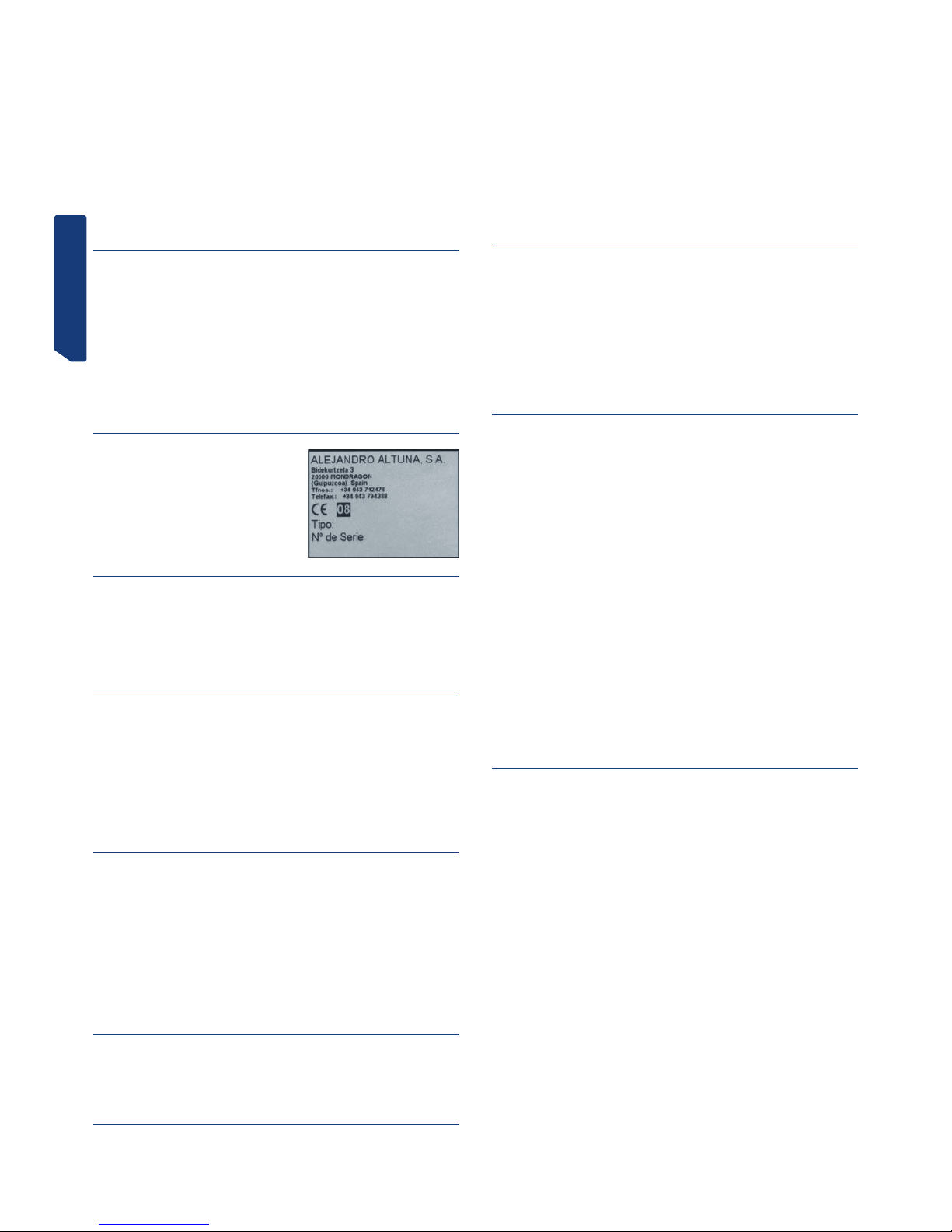
1.3 IDENTIFICATION LABEL
The DAKAR EVOLUTION key cutting machine has an identification label, giving the
machine’s serial or registration number, the
manufacturer’s name and address, the CE
mark and year of manufacture.
2. - CHARACTERISTICS OF THE MACHINE
The DAKAR EVOLUTION machine is a highly robust and precision key cutting machine,
which stands out for having a clamp that enables many different types of keys to be
clamped, without the need for any adaptors.
It incorporates a novel force control system, which increases cutting precision.
2.1 FAMILIES OF KEYS
The DAKAR EVOLUTION machine cuts the following types of keys, among others:
- Dimple keys
- Wave keys
- Tubular keys
- FC6 and FC120 keys
- TK23, TK24 and TK25 keys
- JIS4P keys
- TB1P5 keys
2.2 ACCESSORIES
The machine is supplied with a number of accessories for its use and maintenance. All
these accessories can be housed in the machine’s tool store.
- 2 fuses (housed in the bottom of the tool store)
- Set of Allen keys (5, 3 and 2.5)
- 1 special 1.5 short-arm Allen key
- 2 tip-stop strips
- 2 jaw adjustment rods.
- 2 adaptors for CHI9T tubular key
- Cutters: F-1 and F-13
- Tracer points: T-1 and T-13.
2.3 TOOL STORE
The machine has a tool store, which is fitted to the top of the machine. It can be removed and laid directly on a table (in this way providing extra space on top of the machine,
which can be used for keeping keys, accessories, etc…).
2.4 ELECTRIC CIRCUIT
The main components of the electric and electronic circuits are as follows:
Socket.
Connection plate.
3-position switch.
Transformer.
Motor.
Keypad-display.
Control card.
Cutter.
Tracer point.
Clamp.
Lighting LED.
Force sensor.
See Figure 2
2.5 TECHNICAL DATA
Motor: Single phase 400 W. ,230 V - 50 Hz (Optional: Single phase 400W, 110V – 60Hz)
Cutter: HSS (Optional: Hard metal)
Cutter speed: 6,000 and 11,000 r.p.m.
Clamps: Two clamping faces and 0 / 45 º tilting
Displacement: On three axes with precision roller guides.
Effective stroke: X axis = 71 mm; Y axis = 62 mm; Z axis = 40 mm
Lighting: LED
Dimensions: Width = 430 mm, Depth = 385 mm and Height = 485 mm
Weight: 25 Kg
2.6 MAIN ELEMENTS OF THE MACHINE
1.- Keypad-display
2.- Clamp-holder slide (X – Y axes)
3.- Slide activation lever, x – y axes
4.- Knob to block clamp-holder slide, x axis
5.- Slide spring mechanism activation wheel, x-axis
6.- Clamp
7.- Lever to block clamp rotation
8.- Clamp knob
9.- Head (Z axis)
10.- Lever to activate and block head, z axis
11.- Tracer point spring mechanism knob
12.- Tool-holder
13.- Cutter
14.- Tracer point
15.- Tracer point height adjustment wheel
16.- Main switch
17.- Motor speed selector (2 speeds)
18.- Lighting LEDs
19.- Swarf protector
20.- Tool store
21.- Cutter blocking button
See Figure 3
2.7 COMPONENTS AND FUNCTIONAL PARTS
2.7.1 CHANGING THE CUTTER AND TRACER POINT (21)
To release the cutter, you have to press the cutter blocking button and at the same time
rotate the tool-holder by hand.
After removing the cutter to be replaced, insert the new cutter and secure it in the toolholder, making sure that its end butts up against the inside of the tool-holder.
The tracer point is replaced in the same way as the cutter. The only difference to bear in
mind is that the rotation of the tracer point is always blocked internally.
2.7.2 BLOCKING THE SLIDE AT THE END OF THE “Y” AXIS TRAVEL
In order to prevent the slide from moving in the “Y” direction, whilst the key cutting
machine is holding the keys in the clamp, the slide has been equipped with momentary
blocking in that direction.
To active this blocking, just move the slide as far as it will go in the direction towards
to the key cutting machine.
To deactivate the blocking, just move the slide forward, exercising a little force.
2.7.3 CLAMP (6)
The features of the clamp on the DAKAR EVOLUTION key cutting machine are superior
to those of any normal machine on the market, as it has two separate clamping faces.
In addition, the clamps can be blocked in any rotation position between 45º 0º -45º.
2.7.4 TRACER POINT SPRING MECHANISM (11)
The tracer point can be used in two different ways, depending on the work you are
going to do:
ENGLISH
- Tracer point with spring mechanism. The tracer point spring mechanism is
only used for cutting dimple keys.
- Tracer point blocked. The blocked tracer point is used to carry out cutting
operations with the slide forward. In general, for cutting wave keys.
To activate or deactivate the tracer point spring mechanism, you just have to turn the
tracer point spring mechanism knob 180º (half turn).
When the tracer point spring mechanism is activated, the tracer point tip is located
slightly below its adjustment position in relation to the cutter. This tracer point position
enables you to insert it gently into the hole in the original key, before the cutter starts
cutting the key to be copied. This avoids any vibrations and sudden movements of the
slide.
To find out the status of the tracer point at any time (with spring mechanism or blocked),
there is an indicator on the machine’s keypad-display which provides this information. If
the light is on, the spring mechanism is activated. On the other hand, if the light is off,
the tracer point is blocked.
2.7.5 SPRING MECHANISM AND BLOCKING OF THE SLIDE ON THE
“X” AXIS (5 AND 4)
We recommend that you use the spring mechanism for the slide on the “X” axis to carry
out lateral cutting of wave keys.
We recommend you use the blocking of the slide on the “X” axis for cutting or dimpling
in a straight line.
2.7.6 SUPPORT LEVER FOR TUBULAR KEYS
The DAKAR EVOLUTION key cutting machine has a fold-away lever on its top-left side
which helps to make cutting tubular keys, wave keys, etc. more comfortable, as it serves as a support point for the hand activating the slide travel lever.
2.7.7 CUTTER SPEED (17)
The machine has a speed selector on its right side, which enables you to select the
cutter rotation speed. In general terms, you can say that the rotation speed depends
on the cutter material:
- Position I: To work with an HSS cutter (6,000 rpm)
- Position II: To work with a HARD METAL cutter (11,000 rpm)
- Position O: Cutter at rest.
2.7.8 KEYPAD-DISPLAY (1)
ON-OFF button
Press it for the keypad-display functions to go into ACTIVE mode. A green light will
appear next to the button.
Press it again for the keypad-display to go into STAND-BY mode. A red light will appear
next to the button.
Lighting button
Press it to switch on the lighting diodes (if they are off) or switch them off if they are on.
This button operates independently of the status of the “ON-OFF” button.
SPRING MECHANISM indicator
If the blue light is on, this means that the tracer point is in SPRING MECHANISM ACTIVATED mode.
If the blue light is off, this means that the tracer point is BLOCKED (spring mechanism
deactivated).
MODE button
This button is for activating-deactivating operation of the tracer point vertical adjustment system.
TRACER POINT ADJUSTMENT indicators.
The light on the left comes on when the tracer point is touching the key.
The light on the right comes on when the cutter is touching the key.
FORCE visual indicator.
Indicates the ideal force to be applied during cutting.
NOTE: In addition to the visual indicator, the force control system also has an audible
indicator that emits a sound when you have achieved the ideal cutting force. This audible indicator can be activated-deactivated by pressing the MODE and ON-OFF buttons
at the same time.
2.7.9 VERTICAL ADJUSTMENT OF THE TRACER POINT (15)
Each time the cutter-tracer point is changed, the tracer point has to be vertically adjusted.
In order to be able to use the tracer point electronic vertical adjustment system, the
keypad-display must be active (when it is active, a green light appears next to the
ON-OFF button).
When the keypad-display is active, you can activate-deactivate the tracer point electronic vertical adjustment system by pressing the MODE button.
To vertically adjust the tracer point, proceed as follows:
• Secure the cutter and tracer point in their corresponding tool-holders. Make sure
that they have been secured, inserted upwards as far as they go.
• Secure two similar keys in the machine clamps.
• Release the tracer point spring mechanism (tracer point blocked).
• Lower the head, until the cutter and the tracer point rest on the keys in the
clamps. Then, one of the following three situations will occur:
LEFT BLUE LIGHT. If only the blue light on the left comes on, this means that
the tracer point is touching the key, but the cutter is not. Therefore, you have to
turn the cutter adjustment wheel to the left, until both adjustment lights some on.
RIGHT BLUE LIGHT. If only the blue light on the right comes on, this means that
the cutter is touching the key, but the tracer point is not. Therefore, you have to
turn the tracer point adjustment wheel to the right, until both adjustment lights
come on.
LEFT AND RIGHT BLUE LIGHTS. This means that both the cutter and tracer
point are touching their respective keys. This means that the height of the tracer
point has been adjusted.
IMPORTANT NOTE: When adjusting the height of the tracer point, you need to bear
in mind the type of key you are going to cut. If it is a WAVE key, very little force needs
to be applied to the head activation lever (on the visual force indicator no light should
come on). On the other hand, if it is a DIMPLE key, the blue adjustment lights have to
come on, and the force indicator should indicate the ideal cutting force for dimple keys
(to achieve this, you have to apply a slight force on the head activation lever).
2.7.10 CONTROL OF CUTTING FORCE
The DAKAR EVOLUTION machine has a revolutionary cutting force control system. This
is a patented system, which when you are cutting DIMPLE keys, indicates the ideal
force to exercise on the head activation lever. It has two indicators for this purpose:
Visual indicator. The ideal cutting force is achieved when the line of lights reaches the white arrow.
Audible indicator. When the line of lights reaches the white arrow, the machine
emits a sound. This audible indicator can be activated-deactivated by pressing the
MODE and ON-OFF buttons at the same time.
This cutting force control system enables you to cut DIMPLE keys with great precision.
You will cut the holes in the key with exactly the same force with which you have
adjusted the height of the tracer point. In this way, you obtain maximum precision in
cutting DIMPLE keys.
3.- CUTTING
3.1 CUTTING PROCESS
• Switch on the machine using the main switch located on the back right-hand side
of the machine.
• To improve visibility in the work area, activate the lighting by turning on the switch
located on the keypad-display.
• With the help of the table provided in this manual, select the cutter and tracer
point necessary to cut the key.
• Change the cutter and tracer point.
• Momentarily block the slide at the end of the “Y” axis travel.
• Secure the original key in the left side of the clamp, and the key to be cut in the
right side. When securing the keys, bear in mind the following details:
- KEY STOP. It may be a key which is stopped from being inserted further by its
shoulders (Fig. 4.A), or a key stopped by its tip (Fig. 4.B).
- ADAPTOR. For some very specific types of key, it may be necessary to use an
adaptor.

ENGLISH
- ANGLE CUT. Some keys have angle cut dimples, for which it is necessary to
rotate the clamp.
• Carry out the vertical adjustment of the tracer point.
• Activate the systems which simplify the cutting work:
TRACER POINT: Activate or deactivate the tracer point spring mechanism,
depending on the type of key being cut.
SLIDE: Based on the model of key, it may be a good idea to activate the slide
spring mechanism, or block the slide in the “X” direction.
SUPPORT: Depending on the type of key, it may be a good idea to use the support
lever for tubular keys.
• Start rotating the cutter, having first selected one of the two speeds available.
• Proceed to cut the key. If it is a dimple key, use the help of the cutting force
control system.
3.2 CUTTING KEYS
3.2.1 KB2, KB4 AND KB5 KEYS.
• Different pairs of cutters and tracer points are used depending on the key to be cut.
See table.
• The key is secured in the clamp when its shoulders stop it from being inserted any
further.
• Depending on the model of key to be cut, it is necessary to rotate the clamps based
on the angle required. See table.
• It is necessary to activate the tracer point spring mechanism.
• Use the cutting force control system to increase cutting precision.
• NOTE: The dimples cut on the KB4 key must always be on the lowest part of the
clamp.
• NOTE: The dimples cut on the KB2 key must always be on the highest part of the
clamp.
See Fig. 5
3.2.2 KC1 KEY.
• Use cutter-tracer point pair: F-1 / P-1.
• The key is secured in the clamp when its shoulders stop it from being inserted any
further, but in this case it is inserted from the back.
• It is necessary to position the clamps at an angle of 5º.
• It is necessary to activate the tracer point spring mechanism.
• Use the cutting force control system to increase cutting precision.
• NOTE: The dimples cut on the KC1 key must always be on the highest part of the
clamp.
• NOTE: You have to use the relevant adaptor to cut the lateral dimples.
See Fig. 6
3.2.3 SE1L KEY.
• Use cutter-tracer point pair: F-3 / P-3.
• The key is secured in the clamp when its shoulders stop it from being inserted any
further.
• It is necessary to block the tracer point (deactivate the spring mechanism).
• NOTE: After vertically adjusting the tracer point, you need to slightly lower the
tracer point, by turning the adjustment wheel 5 points to the right. Then you have to
insert the tracer point in the channel of the bit and block the machine head. Next slightly
raise the tracer point so that it does not drag the key.
• NOTE: Enter through the middle of the channels without touching the sides, and on
the second pass enter from the right side and exit from the left, without exercising any
pressure (just gently supporting the tracer point).
• NOTE: To cut the lateral dimples, use the cutter-tracer point combination: F-1 /
P-1. Insert until shoulders stop the key from going in any further. Activate the tracer
point spring mechanism and use the cutting force control system.
See Fig. 7
3.2.4 HF42P15 AND YM22P15 KEYS
• Use cutter-tracer point pair: F-11 / P-11.
• The key is secured in the clamp when its tip stops it from being inserted any further.
• It is necessary to block the tracer point (deactivate the spring mechanism).
• NOTE: After vertically adjusting the tracer point, you need to slightly lower the
tracer point, by turning the adjustment wheel 5 points to the right. Then you have to
insert the tracer point in the channel of the bit and block the machine head. Next slightly
raise the tracer point so that it does not drag the key.
• NOTE: We recommend using the slide spring mechanism system.
• NOTE: We recommend you do a roughing pass and then another finishing pass
following the whole profile of the pattern of the key. Machine in a downward direction
(from the tip of the key to the head).
See Fig. 8
3.2.5 HF40P18 AND HF38P17 KEYS
• Use cutter-tracer point pair: F-11 / P-11.
• Secure the key in the clamp using the AD-MM2 adaptor.
- Position the adaptor on the clamp, so that it is stopped by the tip.
- Insert the key into the adaptor.
- As you secure the adaptor in the clamp, the key is secured in the adaptor.
• It is necessary to block the tracer point (deactivate the spring mechanism).
• NOTE: After vertically adjusting the tracer point, you need to slightly lower the
tracer point, by turning the adjustment wheel 5 points to the right. Then you have to
insert the tracer point in the channel of the bit and block the machine head. Next slightly
raise the tracer point so that it does not drag the key.
• NOTE: We recommend using the slide spring mechanism system.
See Fig. 9
3.2.6 TUBULAR KEYS
• Use cutter-tracer point pair: F-8 / P-8.
• Secure the key in the clamp “V”.
• It is necessary to activate the tracer point spring mechanism.
• The cutting operation is more comfortable if you rest the hand activating the slide
activation lever on the support lever for tubular keys.
See Fig. 10
3.2.7 FC6 AND FC120 KEYS
• Use cutter-tracer point pair: F-11 / P-11.
• Secure the key in the clamp, resting it against the bottom and pushing it towards
the front face of the clamp.
• It is necessary to block the tracer point (deactivate the spring mechanism).
• Block the machine head at a height at which the cutter passes over the clamp but
without brushing against it.
• Cut the two top sides.
• Turn the keys taking care to remove any burrs to ensure correct positioning and
clamping of the key, and cut the other two sides of the key.
See Fig. 11
3.2.8 TK23, TK24 AND TK25 KEYS.
• Use cutter-tracer point pair: F-15 / P-15.
• Secure two key blanks in the clamp, and use them to vertically adjust the tracer
point.
• Clamp the original key with the teeth facing upwards (as shown in the drawing).
• It is necessary to block the tracer point (deactivate the spring mechanism).
• Insert the tracer point precisely in one of the dimples, and block the machine head
at that height.
• Start cutting.
See Fig. 12
3.2.9 JIS4P KEY
• Use cutter-tracer point pair: F-11 / P-11.
• Secure the key in the clamp using the AD-MJ adaptor.
-Position the adaptor on the clamp, so that it is stopped by the tip.
-Insert the key into the adaptor, until its shoulders are stopped by the plate that
rotates. In this position, clamp the key in the adaptor.
• It is necessary to block the tracer point (deactivate the spring mechanism).
See Fig. 13
3.2.10 TB1P5 KEY
• Use cutter-tracer point pair: F-22 / P-22.
• Secure the key in the clamp, using the relevant adaptor.
- Position and secure the adaptors on the clamp.
- When positioning the key, make sure that it is really flat, so that the two cuts
are the same.
• It is necessary to block the tracer point (deactivate the spring mechanism).
• Insert the tracer point if the groove of a letter. Block the machine head and raise
the tracer point slightly so that it does not knock against the adaptor.
• Start cutting.
See Fig. 14
Reading the code on the original key
• The original key has 6 cutting positions, which are defined by the letters: A, B, C, D, E
and F, as shown in the figure below.
• In each of the key’s positions, there are 4 different possible combinations (defined by
numbers), which we are going to indicate and number:
ENGLISH
1 2 3 4
• Height no. 1, indicates that it should not be cut. Position no. 2 indicates there is a
small notch in the key and when it is slightly deeper this is position no. 3. Height no. 4
is the deepest notch in the key.
• You then take the key and mark the combinations of each of the 6 positions, as
shown below, by way of example:
POSITION A B C D E F
COMBINATION 3 4 1 2 4 2
NOTE: The series of combination numbers is the key code.
3.2.11 MD13R KEY.
• Special positioning in the clamp. See figure.
See Fig.15
3.2.12 TS14 AND TS12 KEYS
• Special positioning in the clamp. The TS14 is clamped as shown in the drawing.
• The TS12 key has the peculiarity that to machine the left side it is clamped like the
TS14 and to machine the right side the key has to be clamped by the back part of the
clamp (like with the MD13R key).
See Fig. 16
4.- MAINTENANCE
When carrying out any maintenance work, it is necessary to meet the following requirements:
1. Never carry out any maintenance work with the machine switched on.
2. Unplug the machine.
3. Strictly adhere to the indications in this manual.
4. Only use original spare parts.
4.1 REPLACING THE CLAMP JAWS
The DAKAR EVOLUTION machine’s clamp has three pairs of jaws (left fixed jaw, right
fixed jaw and moving jaw). If any of them become damaged, you can replace them with
new jaws, separately.
To replace the left fixed jaw (A) or the right fixed jaw (B), you just have to undo the two
screws securing them, and remove them by pulling them upwards. Reverse the process
to fit the new jaws.
To replace the moving jaw (C), you need to follow the steps below:
1) With the help of a cutter or something similar, remove the clamp knob’s black
plastic cover.
2) Whilst locking the locknut with a size 14 spanner, insert a no. 5 Allen key into the
hole revealed in the clamp knob, and unscrew it.
3) Tilt the clamp 45º, and manually turning the spindle, remove it from one of the
sides. Once the spindle has been removed, the moving jaw is released and you can
remove it.
4) To fit the new moving jaw, simply reverse the process.
IMPORTANT NOTE: When you replace the left fixed jaw or the right fixed jaw, you
always have to adjust the pair of jaws that has been replaced. On the other hand, if you
replace the moving jaw, it is not necessary to carry out any adjustment on the jaws.
See Fig. 17
4.2 ADJUSTING THE JAWS
Whenever you replace the left fixed jaw or the right fixed jaw, you have to adjust the
pair of jaws that has been replaced. On the other hand, the replacement of the moving
jaw does not require any adjustment to the jaws.
There are two different ways of adjusting the jaws:
NORMAL adjustment
PRECISION adjustment
4.2.1 NORMAL ADJUSTMENT
This is a quick, simple adjustment, which will give you an acceptable adjustment
enabling you to cut keys with a certain amount of precision.
To carry out this adjustment, follow these steps:
1) Secure the two adjustment rods in their relevant tool-holders, inserting then as far
as they will go into the tool-holder, with the tapered part of the adjustment rods on the
outside.
2) The left fixed jaw on the right-hand side of the clamp and the right fixed jaw on the
left-hand side of the clamp cannot be adjusted, as they are held in position by means
of pins. So you have to fit them, by guiding them with their pins and then securing them
with their corresponding screws.
3) Therefore, knowing that in each pair of jaws there is one with a fixed position, you
have to adjust the other jaw in relation to the one with the fixed position.
4) Insert the screws for the jaw to be adjusted, but do not tighten them. So that the
jaw can be moved by hand, but cannot lift up from the surface it is resting on.
5) Adjust the jaw:
5.1) Insert the tracer point adjustment rod into hole no. 1 in the jaw.
5.2) Make the cutter adjustment rod coincide with hole no. 1 in the other jaw.
5.3) Raise the head and carry out the same operation, with hole no. 2 in the jaws.
5.4) Repeat this operation as many times as necessary until the adjustment rods
enter smoothly without the need for any force, in both hole no. 1 and hole
no. 2.
5.5) With the two adjustment rods inserted in holes no. 1, block the head, and
slightly tighten screw B.
5.6) With the two adjustment rods inserted in holes no. 2, block the head and
slightly tighten screw A.
5.7) Repeat the above operation, but fully tightening screws A and B.
5.8) Once you have completed the adjustment process, with the help of the special
short-arm 1.5 Allen key, tighten the two setscrews located between the clamp
knob and the jaw you have adjusted. This will ensure that the jaw you have adjusted is tightly secured.
ENGLISH
4.2.2 PRECISION ADJUSTMENT
This adjustment requires a certain amount of skill, and ensures that the replaced jaws
are very precisely adjusted.
To carry out this adjustment, follow these steps:
1) The left fixed jaw on the right-hand side of the clamp and the right fixed jaw on the
left-hand side of the clamp cannot be adjusted, as they are held in position by means
of pins. So you have to fit them, by guiding them with their pins and then securing them
with their corresponding screws.
2) Therefore, knowing that in each pair of jaws there is one with a fixed position, you
have to adjust the other jaw in relation to the one with the fixed position.
3) Insert the screws for the jaw to be adjusted, but do not tighten them. So that the
jaw can be moved by hand, but cannot lift up from the surface it is resting on.
4) With the help of the special short-arm 1.5 Allen key, unscrew the two jaw adjustment setscrews about 1 turn (these are the two setscrews located between the
clamp knob and jaw you are going to adjust).
5) Then, insert any cutter-tracer point pair in their corresponding tool-holders, but
the wrong way around (with the cutting tips inside the tool-holder). Lower the machine
head, and block it at a height at which the tools can touch the sides of the jaws.
6) Activate the tracer point electronic vertical adjustment system.
7) Rest the end of the jaw that is clamped (the one with the fixed position) against
the side of the tool. Manually, move the jaw to be adjusted in the direction of the clamp
knob, and maintaining pressure on the jaw in that direction, move it forward until it also
touches the side of its corresponding tool. In this position, tighten the screws securing
the jaw a little. You will know when the tools are touching their corresponding jaws,
because the tracer point electronic vertical adjustment system’s lights will come on.
8) Then, separate the moving jaw from the jaw to be adjusted, turning the clamp knob
to do so.
9) Position the tool in alignment with one of the screws securing the jaw, and in this
position rest the tool against the jaw that is clamped (the one with the fixed position).
Then, keeping at all times a slight pressure between the tool and the jaw that is clamped (the one with the fixed position), very slowly tighten the setscrew aligned with the
tool and the jaw screw. The moment will come when the second light on the tracer point
electronic vertical adjustment system will come on. When this happens, stop tightening
the setscrew.
10) Position the tool in alignment with the other screw securing the jaw, and carry out
the same operation again.
11) Check again that the jaws are adjusted in those two positions (in front of the
clamping screws), and if necessary, slightly adjust the position of the jaw tightly very
slightly the corresponding setscrew.
12) You have now completed the adjustment. Now you have to fully tighten the two
screws securing the jaw.
13) Finally, tighten the two jaw adjustment setscrews a little. This will ensure that the
jaw you have adjusted is tightly secured.
4.3 REPLACING THE FUSES
If the machine does not start when you activate the on-off switches, you need to check
the fuses. You can do this in the following way:
1) Switch of the machine using the main switch and unplug it.
2) Remove the fuse-holder which is under the main switch.
3) Use a tester to check if a fuse has blown and, if so, replace it with one of the same
type and value.
4.4 TIGHTENING AND REPLACING THE BELT
To check the tightness of the belt or to replace it, follow these steps:
1) Switch off the machine using the main switch, and unplug it.
2) Undo the 4 screws (5) securing the head guard and remove it. The screws are on
the right side, the left side, on the top and at the back. To remove the head guard it is
necessary first of all to push the cutter locking button right in as far as it will go (E).
3) Loosen but do not undo the 4 screws (6) securing the motor.
4) Loosen but do not undo the 2 locknut nuts (7).
Tightening: When you turn the two tightening screws (8), the motor moves towards
the back of the machine. When you see that the belt is tight enough, tighten up the two
locknut nuts (7) again, and the screws (6) securing the motor.
Replacement: Loosen but do not undo the 2 screws tightening the belt (8). Remove the
damaged belt and replace it with a new one. When you turn the two tightening screws
(8), the motor moves towards the back of the machine. When you see that the belt is
tight enough, tighten up the two locknut nuts (7) again, and the screws (6) securing
the motor.
5) Put the head guard back and secure it in place.
See Fig. 18
4.5 REPLACING THE MOTOR
You can carry out this operation in the following way:
1) Switch off the machine using the main switch and unplug it.
2) Undo the 4 screws (5) securing the head guard and remove it. The screws are on
the right side, the left side, on the top and at the back. To remove the head guard it is
necessary first of all to push the cutter locking button right in as far as it will go (E).
3) Undo the 6 screws (9) securing the motor guard (F) and remove it.
4) Remove the belt (G).
5) Disconnect the power cables going to the motor.
6) Undo the 4 screws (6) securing the motor.
7) Remove the motor.
8) Access the bottom of the motor with a flat screwdriver, block the motor shaft and
manually turn the pulley (H) until it comes out (it is left-threaded).
9) Undo the 4 screws (10) securing the motor support plate and remove it.
10) To fit the new motor, reverse the procedure above.
See Fig. 19
4.6 REPLACING THE KEYBOARD-DISPLAY
You can carry out this operation in the following way:
1) Switch off the machine using the main switch, and unplug it.
2) Undo the 4 screws (5) securing the head guard and remove it. The screws are on
the right side, the left side, on the top and at the back. To remove the head guard it is
necessary first of all to push the cutter locking button right in as far as it will go (E).
3) Disconnect the flat cable connecting the keypad-display (K) to the electronic control card.
4) Release the old keypad-display (K) from the head guard and remove it.
5) To fit the new keypad-display, reverse the procedure above.
See Fig. 20

ENGLISH
4.7 REPLACING THE ELECTRONIC CONTROL CARD
You can carry out this operation in the following way:
1) Switch off the machine using the main switch and unplug it.
2) Undo the 4 screws (5) securing the head guard and remove it. The screws are on
the right side, the left side, on the top and at the back. To remove the head guard it is
necessary first of all to push the cutter locking button right in as far as it will go (E).
3) Disconnect the electronic control card’s main connector (L)
4) Disconnect the flat cable connecting the keypad-display (K) to the electronic control card
5) Undo the 3 screws (11) securing the electronic control card (L) to the head guard
and remove it.
6) To fit a new electronic control card, reverse the procedure above.
See Fig. 21
4.8 REPLACING THE POWER CARD AND CIRCUIT
BREAKER
You can carry out this operation in the following way:
1) Switch off the machine using the main switch and unplug it.
2) Unscrew the machine’s 4 feet (P) and remove them.
3) Undo the 5 screws (12) the lower protection plate and remove it.
4) Disconnect all the cables from the card you want to replace, noting down beforehand the position of each cable.
5) To release the power card (M) or the circuit breaker (N), just press on the lugs on
each of the 4 pins holding it, and pull the card up.
6) To fit the new power card or circuit breaker, just reverse the procedure above.
See Fig. 22
5.- SAFETY
For your safety, we recommend that you follow these guidelines:
• Do not try and start or operate the machine until all the safety aspects, installation
instructions, operators’ guide and maintenance procedures have been complied with
and understood.
• Always disconnect the mains electricity supply, before carrying out any cleaning or
maintenance work.
• Always keep the machine and the area around it clean.
• Work with dry hands.
• Use protective goggles, even if the machine is fitted with guards.
• Make sure that the machine has an earth connection.
We recommend that you work with the machine at a height at which you feel comfortable:
• It is best to work whilst sat in a chair. Adjust the height of the chair so that your
eyes are at the height of the highest part of the machine.
• If you work standing up, depending on your height, it is advisable to place something between the table and the machine to raise the machine so that your eyes are
level with the highest part of the machine.
6.- WASTE DISPOSAL
Waste is understood to be any substance or object from human activities or natural
cycles, that is no longer being used or not intended for any further use.
6.1 PACKING
• As the packing the DAKAR EVOLUTION comes in is made of cardboard, it can be
recycled as packing.
• As waste, it is comparable to solid urban waste and, therefore, can only be disposed in special containers for cardboard.
• The elements protecting the machine inside the cardboard box are made of polymeric material comparable to solid urban waste and, therefore, can only be disposed of
in the normal installations for waste disposal.
6.2 SWARF
• The waste from the key cutting process is classified as special waste, but is comparable to solid urban waste, like for example a metal scouring pad.
• This waste shall be disposed of as classified by the laws currently in force in the
EU, by taking it to special installations for waste disposal.
6.3 MACHINE
• Before demolishing the machine it is necessary to put it out of action first, cutting
off the electricity supply and separating the plastic parts from the metal parts.
• After carrying out this operation, all the waste can be disposed of in compliance
with the laws in force in the country in which the machine was used.
7.- KEY-CUTTER-TRACER POINT-ANGLE CUTADAPTOR TABLE
To be able to do the work properly, the machine has a series of accessories:
See final list.
8.- EXPLODED VIEW
See Fig. 23

FRANCAISE
DAKAR
EVOLUTI0N
NOTICE D’UTILISATION
MACHINE DUPLICATRICE

FRANCAISE
TABLE DES MATIÈRES
1.1 GÉNÉRALITÉS
1.2 TRANSPORT ET EMBALLAGE
1.3 PLAQUE SIGNALÉTIQUE
2. - CARACTÉRISTIQUES DE LA MACHINE
2.1 FAMILLES DE CLÉS
2.2 ACCESSOIRES
2.3 MAGASIN À OUTILS
2.4 CIRCUIT ÉLECTRIQUE
2.5 CARACTÉRISTIQUES TECHNIQUES
2.6 PRINCIPAUX ÉLÉMENTS DE LA MACHINE
2.7 COMPOSANTS ET PARTIES FONCTIONNELLES
2.7.1 CHANGEMENT DE FRAISE ET DE PALPEUR (21)
2.7.2 VERROUILLAGE DU CHARIOT EN FIN DE COURSE DE L’AXE “Y”
2.7.3 ÉTAU (6)
2.7.4 DISPOSITIF D’AIDE À RESSORT DU PALPEUR (11)
2.7.5 DISPOSITIF D’AIDE À RESSORT ET VERROUILLAGE DU CHARIOT SUR L’AXE “ X “ (5 ET 4)
2.7.6 LEVIER D’APPUI POUR CLÉS TUBULAIRES
2.7.7 VITESSE DE LA FRAISE (17)
2.7.8 AFFICHEUR-CLAVIER (1)
2.7.9 RÉGLAGE VERTICAL DU PALPEUR (15)
2.7.10 CONTRÔLE DE LA FORCE DE REPRODUCTION
3.- CHIFFRAGE
3.1 PROCESSUS DE CHIFFRAGE
3.2 CHIFFRAGE DES CLÉS
3.2.1 CLÉS KB2, KB4 ET KB5.
3.2.2 CLÉ KC1.
3.2.2 CLÉ SE1L.
3.2.4 CLÉS HF42P15 ET YM22P15
3.2.5 CLÉS HF40P18 ET HF38P17
3.2.6 CLÉS TUBULAIRES
3.2.7 CLÉS FC6 ET FC120
3.2.8 CLÉS TK23, TK24 ET TK25.
3.2.9 CLÉ JIS4P
3.2.10 CLÉ TB1P5
3.2.11 CLÉ MD13R.
3.2.12 CLÉ TS14 ET TS12
4.- MAINTENANCE
4.1 REMPLACEMENT DES MORS DE L’ÉTAU
4.2 RÉGLAGE DES MORS
4.2.1 RÉGLAGE NORMAL
4.2.2 RÉGLAGE DE PRÉCISION
4.3 CHANGEMENT DES FUSIBLES
4.4 TENSION ET CHANGEMENT DES COURROIES
4.5 CHANGEMENT DU MOTEUR
4.6 REMPLACEMENT DE L’AFFICHEUR-CLAVIER
4.7 REMPLACEMENT DE LA CARTE ÉLECTRONIQUE DE CONTRÔLE-COMMANDE
4.8 REMPLACEMENT DE LA CARTE DE PUISSANCE ET DU DISJONCTEUR
5.- SÉCURITÉ
6.- ÉLIMINATION DES DÉCHETS
6.1 EMBALLAGE
6.2 COPEAUX
6.3 MACHINE
7.- TABLE CLÉ-FRAISE-PALPEUR-INCLINAISON-ADAPTATEUR
8.- VUE ÉCLATÉE
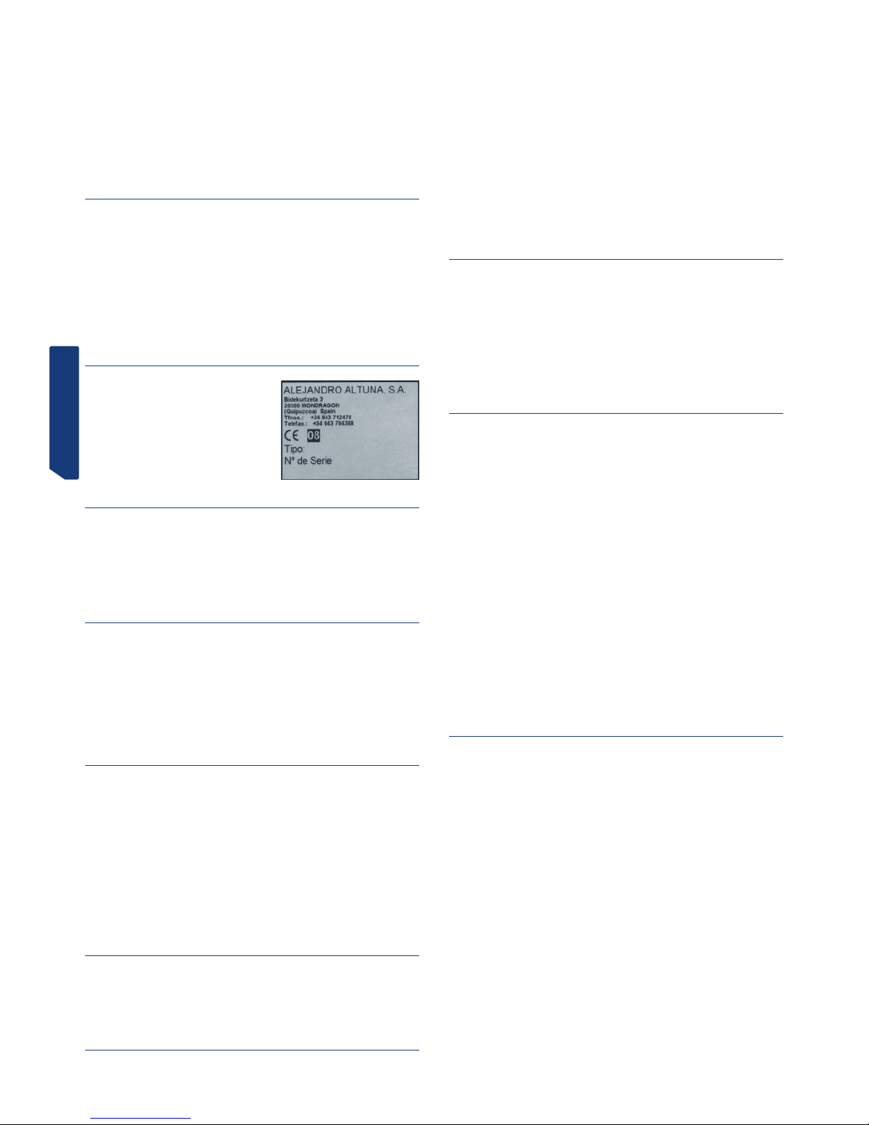
FRANCAISE
1.1 GÉNÉRALITÉS
La machine duplicatrice de clés modèle DAKAR EVOLUTION a été conçue en tenant
compte des réglementations de sécurité en vigueur dans la C.E.E.
La sécurité du personnel appelé à manœuvrer ce type de machines ne peut être assurée
qu’à partir d’une procédure de sécurité personnelle minutieuse, basée sur la mise en
place d’un programme de maintenance et le suivi des recommandations ainsi que sur le
respect des consignes de sécurité préconisées dans cette notice.
Même si l’installation de la machine n’offre aucune difficulté, il est préférable de ne pas
essayer de l’installer, de la régler et de la manipuler sans lire d’abord la notice.
La machine sort de notre usine prête à l’emploi et ne demande que quelques opérations
d’étalonnage en fonction des outils qui vont être utilisés.
1.2 TRANSPORT ET EMBALLAGE
La machine est livrée dans une boîte en carton robuste, protégée par une mousse
d’emballage, aux dimensions suivantes :
Largeur = 520 mm ; hauteur = 650 mm ; profondeur = 575 mm
Poids de la duplicatrice avec l’emballage = 30 kg
Au déballage de la machine, l’examiner soigneusement pour vérifier qu’elle n’a souffert
aucun dommage pendant le transport.
Si une anomalie est détectée, avertir immédiatement le transporteur et ne pas toucher
à la machine jusqu’à ce que son agent ait effectué l’inspection correspondante.
Pour déplacer la machine d’un endroit à l’autre, la saisir par sa base et non par ses
autres parties.
1.3 PLAQUE SIGNALÉTIQUE
La machine duplicatrice modèle DAKAR
EVOLUTION porte une plaque signalétique
où sont mentionnés son numéro de série ou
d’immatriculation, le nom et l’adresse du
fabricant, la marque CE et l’année de fabrication.
2. - CARACTÉRISTIQUES DE LA MACHINE
La machine DAKAR EVOLUTION est une duplicatrice à la fois robuste et de haute précision qui se caractérise par les multiples possibilités de serrage qu’autorise son étau,
sans avoir à recourir à des pièces rapportées ou à des adaptateurs.
Par ailleurs, elle incorpore un système innovant de contrôle de force qui accroît la précision du copiage.
2.1 FAMILLES DE CLÉS
Quelques types de clés pouvant être reproduits avec la duplicatrice DAKAR EVOLUTION:
- Clés à points
- Clés à vagues
- Clés tubulaires
- Clés FC6 et FC120
- Clés TK23, TK24 et TK25
- Clés JIS4P
- Clés TB1P5
2.2 ACCESSOIRES
La machine est livrée avec une panoplie d’accessoires pour son usage et son entretien.
Tous ces accessoires peuvent être rangés dans le magasin à outils dont dispose la
machine.
- 2 fusibles (logés dans le bas du magasin)
- Clés allen de 5, de 3 et de 2.5
- 1 Clé allen spécial à bras court de 1,5.
- 2 Plaquettes de butée en pointe
- 2 Axes pour le réglage des mors.
- 2 Adaptateurs pour la clé tubulaire CHI9T
- Fraises : F-1 et F-13
- Palpeurs : T-1 et T-13.
2.3 MAGASIN À OUTILS
La duplicatrice comporte un magasin à outils monté dans sa partie supérieure. Il peut
être retiré pour être installé directement sur un plan de travail (pour dégager par exemple un espace supplémentaire dans le haut de la machine où déposer clés, accessoires,
etc…).
2.4 CIRCUIT ÉLECTRIQUE
Les principaux composants du circuit électrique et électronique sont les suivants :
1. Prise de courant
2. Plaque à bornes
3. Interrupteur 3 positions.
4. Transformateur
5. Moteur
6. Afficheur-clavier
7. Carte de contrôle-commande
8. Fraise
9. Palpeur
10. Étau
11. Diodes électroluminescentes d’éclairage.
12. Capteur de force
Voir Figure 2
2.5 CARACTÉRISTIQUES TECHNIQUES
Moteur : monophasé 400 W, 230 V - 50 Hz (en option : monophasé 400W, 110V – 60Hz)
Fraise : HSS (en option : métal dur)
Vitesse fraise : 6000 et 11 000 tr/min
Mors : à deux faces de serrage et basculants 0 / 45 º
Déplacement : sur trois axes avec guides à rouleaux de précision.
Courses utiles : axe X = 71 mm ; axe Y = 62 mm ; axe Z = 40 mm
Éclairage: diodes DEL
Dimensions : largeur = 430 mm, profondeur = 385 mm et hauteur = 485 mm
Poids : 25 kg
2.6 PRINCIPAUX ÉLÉMENTS DE LA MACHINE
1.- Afficheur-clavier
2.- Chariot porte-étau (axes X – Y)
3.- Levier de manœuvre des chariots, axes x – y
4.- Pommeau de verrouillage du chariot porte-étau, axe x
5.- Roue de manœuvre du système de dispositif d’aide à ressort du chariot, axe x
6.- Étau
7.- Levier de verrouillage de la rotation de l’étau
8.- Pommeau de l’étau
9.- Tête (axe Z)
10.- Levier de manœuvre et de verrouillage de la tête, axe z
11.- Manette du dispositif d’aide à ressort du palpeur
12.- Porte-outils
13.- Fraise
14.- Palpeur
15.- Roue de réglage de la hauteur du palpeur
16.- Interrupteur général
17.- Bouton de vitesse du moteur (2 vitesses)
18.- DEL d’éclairage
19.- Protecteur de copeaux
20.- Magasin à outils
21.- Poussoir de verrouillage de la fraise
Voir figure 3
2.7 COMPOSANTS ET PARTIES FONCTIONNELLES
2.7.1 CHANGEMENT DE FRAISE ET DE PALPEUR (21)
Pour libérer la fraise, presser son bouton de verrouillage tout en faisant tourner à la
main le porte-outil.
Après avoir retiré la fraise à remplacer, introduire la nouvelle fraise et la serrer sur le
porte-outil en veillant à faire butée avec sa pointe à l’intérieur du porte-outil.
Le palpeur se change de la même façon que la fraise. La seule différence à prendre en
compte est que la rotation du palpeur se trouve toujours bloquée intérieurement.
2.7.2 VERROUILLAGE DU CHARIOT EN FIN DE COURSE DE L’AXE “Y”
Pour éviter le déplacement du chariot dans le sens “Y” pendant le serrage des clés dans
l’étau, le chariot a été doté d’un verrouillage momentané sur cet axe.
Pour activer ce verrouillage, il suffit de déplacer le chariot jusqu’à sa fin de course en
direction du duplicateur.
Pour le déverrouillage, déplacer le chariot vers l’avant en exerçant une légère pression.
2.7.3 ÉTAU (6)
Les prestations de l’étau de la duplicatrice DAKAR EVOLUTION sont supérieures à celles d’une machine courante du marché grâce à ses deux faces de serrage indépendantes. De plus, les mors peuvent être verrouillés sur n’importe quelle position de rotation
entre 45º, 0º et -45º.
2.7.4 DISPOSITIF D’AIDE À RESSORT DU PALPEUR (11)

FRANCAISE
Il existe deux façons possibles d’utiliser le palpeur en fonction du travail à réaliser :
- Palpeur avec dispositif d’aide à ressort. Le dispositif d’aide à ressort du
palpeur sert uniquement et exclusivement au chiffrage des clés à points.
- Palpeur bloqué. Le palpeur bloqué s’utilise pour les opérations de copiage avec
avance du chariot. En général, il sert au chiffrage des clés à vagues.
Pour activer ou désactiver ce dispositif d’aide, il suffit de tourner de 180º (demi-
tour) sa manette.
Lorsque le dispositif d’aide à ressort du palpeur est activé, la pointe de ce dernier se
situe légèrement en dessous de sa position de réglage par rapport à la fraise. Cette
position du palpeur permet une introduction en douceur dans le trou de la clé originale,
avant que la fraise ne commence le fraisage de la clé à copier. Ceci évite les vibrations
et les déplacements brusques du chariot.
Pour connaître à tout moment l’état du palpeur (avec dispositif d’aide à ressort ou bloqué), l’afficheur-clavier de la machine comporte un indicateur qui nous renseigne à ce
sujet. Si le voyant est allumé, le dispositif d’aide à ressort est activé. En revanche, s’il
est éteint, le palpeur est bloqué.
2.7.5 DISPOSITIF D’AIDE À RESSORT ET VERROUILLAGE DU CHARIOT SUR L’AXE “ X “ (5 ET 4)
Nous conseillons d’utiliser le système de dispositif d’aide à ressort du chariot sur l’axe
“X” pour effectuer les fraisages latéraux des clés à vagues.
Par contre, nous recommandons le blocage du chariot sur l’axe “X “ pour les fraisages
ou points en ligne droite.
2.7.6 LEVIER D’APPUI POUR CLÉS TUBULAIRES
La duplicatrice DAKAR EVOLUTION dispose, sur le haut de son flanc gauche, d’un double levier rabattable qui rend plus commode le copiage de clés tubulaires, à vagues,
etc., .en offrant un point d’appui pour la main qui manœuvre le levier de translation
des chariots.
2.7.7 VITESSE DE LA FRAISE (17)
La machine comporte un bouton de réglage de la vitesse, situé sur son côté droit, qui
permet de choisir la vitesse de rotation de la fraise. En règle générale, la vitesse de
rotation va dépendre du matériau de la fraise :
- Position I : pour travailler avec des fraises en HSS (6000 t/min)
- Position II : pour travailler avec des fraises en MÉTAL DUR (11 000 t/min)
- Position O : fraise arrêtée.
2.7.8 AFFICHEUR-CLAVIER (1)
Touche ON-OFF
En pressant ce bouton, les fonctions de l’afficheur-clavier passent en mode ACTIF. Un
voyant vert s’allume à côté de la touche.
En la pressant de nouveau, l’afficheur-clavier passe en mode “STAND-BY”. Un voyant
rouge s’allume à côté de la touche.
Touche ÉCLAIRAGE
En la pressant, les diodes d’éclairage s’allument (si elles sont éteintes) ou s’éteignent
(si elles sont allumées).
Cette touche fonctionne indépendamment de l’état de la touche “ON-OFF”.
Indicateur DISPOSITIF D’AIDE À RESSORT
Si la lumière bleue est allumée, cela signifie que le palpeur est en état de DISPOSITIF
D’AIDE À RESSORT ACTIVÉ.
Si elle est éteinte, cela signifie que le palpeur est BLOQUÉ (dispositif d’aide à ressort
désactivé).
Touche MODE
Cette touche sert à activer-désactiver le fonctionnement du système de réglage vertical
du palpeur.
Indicateurs RÉGLAGE DU PALPEUR.
Le voyant de gauche s’allume quand le palpeur touche la clé.
Le voyant de droite s’allume quand la fraise touche la clé.
Indicateur visuel de FORCE.
Il indique la force optimale à exercer pendant la reproduction.
NOTA: Outre l’indicateur visuel, le système de contrôle de force dispose aussi d’un
indicateur sonore qui avertit par un bip que la force optimale de reproduction est atteinte. Cet indicateur sonore peut être activé-désactivé en pressant en même temps les
touches MODE et ON-OFF.
2.7.9 RÉGLAGE VERTICAL DU PALPEUR (15)
À chaque changement de fraise-palpeur, il est nécessaire de régler verticalement le
palpeur.
Pour pouvoir utiliser le système électronique de réglage vertical du palpeur, l’afficheurclavier doit être actif (quand il est actif, un voyant vert s’allume à côté de la touche
ON-OFF).
Avec l’afficheur-clavier actif, il est possible d’activer-désactiver le système électronique
de réglage vertical du palpeur en pressant la touche MODE.
Pour réaliser le réglage vertical du palpeur, procéder de la façon suivante :
• Serrer la fraise et le palpeur sur leur poupée. S’assurer qu’ils sont bien fixés en
faisant butée vers le haut.
• Serrer deux clés identiques dans les étaux de la machine.
• Éliminer le dispositif d’aide à ressort du palpeur (palpeur bloqué).
• Descendre la tête jusqu’à ce que la fraise et le palpeur reposent sur les clés situées dans les étaux. Une des trois situations ci-après est alors possible :
BLEU GAUCHE. Si seul s’allume le voyant de gauche, cela signifie que le palpeur
touche la clé, mais pas la fraise. Il faut donc tourner la roue de réglage du palpeur
vers la gauche jusqu’à ce que s’allument les deux voyants de réglage.
BLEU DROITE. Si seul s’allume le voyant de droite, cela signifie que la fraise
touche la clé, mais pas le palpeur. Il faut donc tourner la roue de réglage du palpeur
vers la droite jusqu’à ce que s’allument les deux voyants de réglage.
BLEU GAUCHE ET DROITE. Ces voyants allumés indiquent qu’aussi bien la fraise
que le palpeur touchent leurs clés respectives. La hauteur du palpeur est maintenant réglée.
REMARQUE IMPORTANTE: En effectuant le réglage en hauteur du palpeur, attention
au type de clé à reproduire. S’il s’agit d’une clé À VAGUES, il faut appliquer très peu
de force au levier de manœuvre de la tête (le voyant de l’indicateur visuel de force ne
doit pas s’allumer). En revanche, pour une clé À POINTS, les deux voyants bleus de
réglage doivent s’allumer en même temps que l’indicateur de force indique la force
idéale de copiage pour les clés à points (pour cela, exercer une légère force sur le levier
de manœuvre de la tête).
2.7.10 CONTRÔLE DE LA FORCE DE REPRODUCTION
La duplicatrice DAKAR EVOLUTION est dotée d’un système de contrôle de la force de
reproduction révolutionnaire. Il s’agit d’un système breveté qui, au moment de copier
des clés à POINTS, nous indique la force optimale à exercer sur le levier de manœuvre
de la tête. Pour ce faire, il dispose de deux indicateurs :
Indicateur visuel. La force optimale de reproduction est atteinte quand la ligne
de traits lumineux atteint la flèche blanche.
Indicateur sonore. Un bip se fait entendre quand la ligne de traits atteint la
flèche blanche. Cet indicateur sonore peut être activé-désactivé en pressant en
même temps les touches MODE et ON-OFF.
Ce système de contrôle de la force de reproduction permet d’obtenir des clés à POINTS
d’une grande précision. Les trous de la clé sont reproduits avec exactement la même
force que celle appliquée pour régler la hauteur du palpeur. Une précision parfaite est
ainsi obtenue lors du copiage des clés à POINTS.
3.- CHIFFRAGE
3.1 PROCESSUS DE CHIFFRAGE
• Allumer la machine en intervenant sur l’interrupteur général placé à l’arrière à

FRANCAISE
droite.
• Pour améliorer la visibilité de la zone de travail, allumer l’éclairage en intervenant
sur l’interrupteur placé sur l’afficheur-clavier.
• À l’aide de la table qui figure dans la présente notice, sélectionner la fraise et le
palpeur nécessaires pour chiffrer la clé.
• Changer la fraise et le palpeur.
• Verrouiller momentanément le chariot en fin de course de l’axe “Y”
• Serrer la clé originale sur la gauche de l’étau et la clé à chiffrer sur la droite.
Attention aux détails suivants au moment de serrer les clés :
- BUTÉE DE LA CLÉ. Il peut s’agir d’une clé à “butée en col” (Fig. 4.A) ou à “butée
en pointe” (Fig. 4.B).
- ADAPTATEUR. Certains modèles de clés précis exigent l’emploi d’un adaptateur.
- INCLINAISON. Certaines clés comportant des points inclinés rendent nécessaire
la rotation de l’étau.
• Procéder au réglage vertical du palpeur.
• Activer les systèmes qui simplifient le travail de copiage :
- PALPEUR : Activer ou désactiver le dispositif d’aide à ressort du palpeur en fonc-
tion du type de clé à chiffrer.
- CHARIOT : selon le modèle de clé, il peut être intéressant d’activer le dispositif
d’aide à ressort du chariot, ou son blocage, sur l’axe “X”.
- APPUI : en fonction du modèle de clé, il peut être intéressant d’utiliser le levier
d’appui pour clés tubulaires.
• Mettre en marche la rotation de la fraise en choisissant d’abord l’une des deux
vitesses disponibles.
• Procéder au chiffrage de la clé. Si la clé est à points, s’aider avec le système de
“contrôle de force de la reproduction”.
3.2 CHIFFRAGE DES CLÉS
3.2.1 CLÉS KB2, KB4 ET KB5.
• En fonction du modèle de clé à copier, utiliser une paire de fraise-palpeur différente. Consulter la table.
• Le serrage de la clé dans l’étau s’effectue par “butée en col”.
• Selon le modèle de clé à copier, faire tourner l’étau jusqu’à l’angle nécessaire.
Consulter la table.
• Activer le dispositif d’aide à ressort du palpeur.
• Pour augmenter la précision du chiffrage, utiliser le système de “Contrôle de force
de la reproduction”.
• NOTA : Les points taillés de la clé KB4 doivent toujours se trouver dans la zone la
plus basse de l’étau.
• NOTA : Les points taillés de la clé KB2 doivent toujours se trouver dans la zone la
plus haute de l’étau.
Voir Fig. 5
3.2.2 CLÉ KC1.
• Utiliser la fraise-palpeur : F-1 / P-1.
• Le serrage de la clé dans l’étau s’effectue par “butée en col”, mais en introduisant
la clé par l’arrière.
• Positionner les étaux sur un angle d’inclinaison de 5º.
• Activer le dispositif d’aide à ressort du palpeur.
• Pour augmenter la précision du chiffrage, utiliser le système de “Contrôle de force
de la reproduction”.
• NOTA : Les points taillés de la clé KC1 doivent toujours se trouver dans la zone la
plus haute de l’étau.
• NOTA : Pour le copiage des points latéraux, utiliser l’adaptateur correspondant.
Voir Fig. 6
3.2.2 CLÉ SE1L.
• Utiliser la fraise-palpeur : F-3 / P-3.
• Le serrage de la clé dans l’étau s’effectue par “butée en col”.
• Bloquer le palpeur (désactiver le dispositif d’aide à ressort).
• NOTA : après avoir réglé verticalement le palpeur, descendre celui-ci très légèrement en tournant la roue de réglage de 5 points vers la droite. Introduire ensuite le
palpeur dans le canal du panneton et verrouiller la tête de la machine. Puis remonter
légèrement le palpeur pour qu’il n’entraîne pas la clé.
• NOTA : entrer par le centre du canal, sans toucher les côtés, et, à la seconde
passe, entrer par le côté droit et sortir par le côté gauche, sans exercer aucune pression
(uniquement en appuyant légèrement le palpeur).
• NOTA : pour la reproduction des points latéraux, utiliser la fraise-palpeur F-1 / P-1
en serrant par “butée en col”. Activer le dispositif d’aide à ressort du palpeur et utiliser
le système de “Contrôle de force de la reproduction”.
Voir Fig. 7
3.2.4 CLÉS HF42P15 ET YM22P15
• Utiliser la fraise-palpeur : F-11 / P-11.
• Le serrage de la clé dans l’étau s’effectue par “butée en pointe”.
• Bloquer le palpeur (désactiver le dispositif d’aide à ressort).
• NOTA : après avoir réglé verticalement le palpeur, descendre celui-ci très légèrement en tournant la roue de réglage de 5 points vers la droite. Introduire ensuite le
palpeur dans le canal du panneton et verrouiller la tête de la machine. Puis remonter
légèrement le palpeur pour qu’il n’entraîne pas la clé.
• NOTA : Il est conseillé d’utiliser le système de dispositif d’aide à ressort du chariot.
• NOTA : Il est recommandé d’effectuer une passe d’ébauche, puis une autre passe
de finition en suivant tout le profil de dessin de la clé. Usiner en sens descendant (de la
pointe de la clé vers la tête).
Voir Fig. 8
3.2.5 CLÉS HF40P18 ET HF38P17
• Utiliser la fraise-palpeur : F-11 / P-11.
• Le serrage de la clé dans l’étau se fait à l’aide de l’adaptateur AD-MM2.
-Positionner l’adaptateur sur l’étau en “butée en pointe”.
-Introduire la clé dans l’adaptateur.
-En même temps que le serrage de l’adaptateur dans l’étau, la clé reste serrée
dans l’adaptateur.
• Bloquer le palpeur (désactiver le dispositif d’aide à ressort).
• NOTA : après avoir réglé verticalement le palpeur, descendre celui-ci très légèrement en tournant la roue de réglage de 5 points vers la droite. Introduire ensuite le
palpeur dans le canal du panneton et verrouiller la tête de la machine. Puis remonter
légèrement le palpeur pour qu’il n’entraîne pas la clé.
• NOTA : Il est conseillé d’utiliser le système de dispositif d’aide à ressort du chariot.
Voir Fig. 9
3.2.6 CLÉS TUBULAIRES
• Utiliser la fraise-palpeur : F-8 / P-8.
• Serrer la clé dans le “V” de l’étau.
• Activer le dispositif d’aide à ressort du palpeur.
• L’opération de taillage sera plus commode en appuyant la main qui manœuvre le
levier du chariot sur le levier d’appui pour clés tubulaires.
Voir Fig. 10
3.2.7 CLÉS FC6 ET FC120
• Utiliser la fraise-palpeur : F-11 / P-11.
• Serrer la clé dans l’étau en l’appuyant sur le fond et en la poussant vers la face
avant de l’étau.
• Bloquer le palpeur (désactiver le dispositif d’aide à ressort).
• Bloquer la tête de la machine à une hauteur telle que la fraise puisse passer sur
l’étau, mais sans le frôler.
• Procéder au taillage des deux côtés supérieurs.
• Tourner les clés en veillant à éliminer les barbes pour assurer un bon positionnement et serrage de la clé et procéder au taillage des deux autres côtés de la clé.
Voir Fig. 11
3.2.8 CLÉS TK23, TK24 ET TK25.
• Utiliser la fraise-palpeur : F-15 / P-15.
• Serrer dans l’étau deux ébauches et réaliser sur elles le réglage vertical du palpeur.
• Serrer la clé originale avec la denture vers le haut (comme le montre le dessin).
• Bloquer le palpeur (désactiver le dispositif d’aide à ressort).
• Introduire le palpeur exactement dans l’un des points et verrouiller la tête de la
machine à cette hauteur.
• Procéder au taillage.
Voir Fig. 12
3.2.9 CLÉ JIS4P
• Utiliser la fraise-palpeur : F-11 / P-11.
• Le serrage de la clé dans l’étau se fait à l’aide de l’adaptateur AD-MJ.
-Positionner l’adaptateur sur l’étau en “butée en pointe”.
-Introduire la clé dans l’adaptateur en “butée en col” contre la plaquette qui tourne. Dans cette position, serrer la clé dans son adaptateur.
• Bloquer le palpeur (désactiver le dispositif d’aide à ressort).
Voir Fig. 13
3.2.10 CLÉ TB1P5
• Utiliser la fraise-palpeur F-22 / P-22.
• Le serrage de la clé dans l’étau se fait à l’aide de l’adaptateur correspondant.
- Positionner et serrer les adaptateurs sur l’étau.
- Attention, en plaçant la clé, à ce qu’elle soit bien plane, pour que les deux taillages soient pareils.
• Bloquer le palpeur (désactiver le dispositif d’aide à ressort).
• Introduire le palpeur dans le canal d’une lettre. Verrouiller la tête de la machine et
remonter légèrement le palpeur pour qu’il ne talonne pas l’adaptateur.

FRANCAISE
• Procéder au taillage.
Voir Fig. 14
Lecture du code de la clé originale
• La clé originale a 6 positions de reproduction, définies par les lettres A, B, C, D, E
et F, comme le montre la figure ci-dessous.
• Pour chacune des positions que possède la clé, il existe 4 combinaisons différentes
possibles (définies par des numéros), énumérées ci-après :
1 2 3 4
• L’“inclinaison” nº 1 indique qu’il ne faut pas reproduire. L’inclinaison nº 2 indique
qu’il y a un petit biseau sur la clé qui, quand il est plus grand, correspond à l’inclinaison
nº 3. L’inclinaison nº 4 correspond au plus grand des biseaux de la clé.
• Il s’agit alors de prendre la clé et de marquer les combinaisons de chacune des 6
positions, comme il est montré ci-après à titre d’exemple :
POSITION A B C D E F
COMBINAISON 3 4 1 2 4 2
NOTA : La série de numéros de la combinaison est le code de la clé.
3.2.11 CLÉ MD13R.
• Mise en place spéciale dans l’étau. Voir la figure.
Voir Fig.15
3.2.12 CLÉ TS14 ET TS12
• Mise en place spéciale dans l’étau. La clé TS14 se serre comme le montre le dessin.
• La clé TS12 présente la particularité que pour usiner le côté gauche elle se serre
comme la TS14 et pour usiner le côté droit il faut serrer la clé par l’arrière de l’étau
(comme dans le cas de la clé MD13R).
Voir Fig. 16
4.- MAINTENANCE
Avant toute opération de maintenance, les conditions suivantes doivent être réunies :
1. Ne jamais effectuer de tâche avec la machine en marche.
2. Débrancher la duplicatrice.
3. Suivre rigoureusement les consignes de cette notice.
4. Utiliser des pièces de rechange originales.
4.1 REMPLACEMENT DES MORS DE L’ÉTAU
L’étau de la duplicatrice DAKAR EVOLUTION comporte trois paires de mors (mors fixe
gauche, mors fixe droit et mors mobile). Si l’une d’elle est endommagée, elle peut être
remplacée séparément par une paire neuve.
Pour remplacer le “mors fixe gauche” (A) ou le “mors fixe droit” (B), il suffit de dévisser
les deux vis de serrage qui le tiennent et de les extraire en tirant vers le haut. Procéder
à l’inverse pour le montage des mors neufs.
Pour remplacer le “mors mobile” (C), la séquence d’opération est la suivante :
1) Extraire à l’aide d’un cutter ou similaire le couvercle plastique noir de la manette
de l’étau.
2) Tout en bloquant le contre-écrou avec une clé fixe de 14, introduire une clé allen de 5
dans l’orifice qui se dégage sur la manette de l’étau et dévisser.
3) Positionner l’étau sur un angle de 45º et en tournant manuellement la broche
l’extraire par l’un des côtés. Une fois la broche retirée, le mors mobile reste libéré et
peut être déposé.
4) Procéder à l’inverse pour le montage du mors mobile neuf.
REMARQUE IMPORTANTE: Après avoir remplacé le mors fixe gauche ou le mors fixe
droit, ne pas oublier de régler la paire de mors neuve. En revanche, dans le cas du mors
mobile, aucune opération de réglage n’est nécessaire.
Voir Fig. 17
4.2 RÉGLAGE DES MORS
Après avoir remplacé le mors fixe gauche ou le mors fixe droit, ne pas oublier de régler
la paire de mors neuve. En revanche, dans le cas du mors mobile, aucune opération de
réglage n’est nécessaire.
Il existe deux façons de procéder au réglage des mors :
Réglage NORMAL
Réglage de PRÉCISION
4.2.1 RÉGLAGE NORMAL
Il s’agit d’un réglage rapide et simple qui assure toutefois un réglage acceptable pour
la reproduction des clés avec une certaine précision.
Séquence d’opération de ce réglage :
1) Serrer les deux axes de réglage dans les porte-outils correspondants de façon à ce
qu’ils soient en butée à l’intérieur du porte-outils et que la partie conique des axes reste
à l’intérieur.
2) Le mors fixe gauche du côté droit de l’étau et le mors fixe droit du côté gauche de
l’étau ne sont pas réglables car ils sont positionnés au moyen de goujons. Il faut donc
les monter en les guidant avec leurs goujons, puis les serrer au moyen des vis correspondantes.
3) Ainsi donc, puisque nous savons que pour chaque paire de mors l'un de ceux-ci a
une position fixe, l’autre se règlera par rapport à celui en position fixe.
4) Placer les vis du mors à régler, mais sans les serrer. de sorte que le mors puisse
être déplacé à la main, mais en l'empêchant toutefois de se soulever par rapport à sa
surface d’appui.
5) Procéder au réglage du mors :
5.1) Introduire l’axe de réglage du palpeur dans l’orifice Nº1 du mors.
5.2) Faire coïncider l’axe de réglage de la fraise avec l’orifice Nº1 de l’autre mors.
5.3) Relever la tête et effectuer la même opération, cette fois-ci dans l’orifice Nº2
des mors.
5.4) Répéter l’étape précédente autant de fois que nécessaire jusqu’à ce que les
axes de réglage entrent en douceur et sans forcer, tant dans l’orifice Nº1 que
dans le Nº2.

FRANCAISE
5.5) Avec les deux axes de réglage introduits dans les orifices Nº1, verrouiller la
tête et serrer légèrement la vis B
5.6) Avec les deux axes de réglage introduits dans les orifices Nº2, verrouiller la
tête et serrer légèrement la vis A.
5.7) Répéter l’étape précédente, mais en serrant définitivement les vis A et B.
5.8) Une fois le réglage terminé, à l’aide de la clé allen de 1,5 spéciale à bras court,
serrer les deux vis prisonnières situées entre la manette de l’étau et le mors qui
vient d'être réglé. Ceci garantit une plus grande sécurité de la fixation du mors que
nous venons de régler.
4.2.2 RÉGLAGE DE PRÉCISION
Il s’agit d’un réglage qui exige une certaine habileté mais qui permet de réaliser un
réglage très précis des mors remplacés.
Séquence d’opération de ce réglage :
1) Le mors fixe gauche du côté droit de l’étau et le mors fixe droit du côté gauche de
l’étau ne sont pas réglables car ils sont positionnés au moyen de goujons. Il faut donc
les monter en les guidant avec leurs goujons, puis les serrer au moyen des vis correspondantes.
2) Ainsi donc, puisque nous savons que pour chaque paire de mors l'un de ceux-ci a
une position fixe, l’autre se règlera par rapport à celui en position fixe.
3) Placer les vis du mors à régler, mais sans les serrer, de sorte que le mors puisse
être déplacé à la main, mais en l'empêchant toutefois de se soulever par rapport à sa
surface d’appui.
4) À l’aide de la clé allen de 1,5 spéciale à bras court, dévisser d’un tour environ les
deux vis prisonnières de réglage du mors (ce sont les deux prisonnières situées entre la
manette de l’étau et le mors à régler).
5) Monter ensuite une paire quelconque de Fraise-Palpeur dans les porte-outils correspondants, mais à l’envers (avec les pointes de coupe vers l'intérieur du porte-outils).
Descendre la tête de la machine et la verrouiller à une hauteur à laquelle les outils
peuvent toucher les flancs du mors.
6) Activer le système électronique de réglage vertical du palpeur.
7) Appuyer l’extrémité du mors qui est serré (celui en position fixe) contre le côté
de l’outil. À la main, déplacer le mors à régler dans le sens de la manette de l’étau
et, en maintenant la pression sur le mors dans cette direction, le déplacer frontalement jusqu’à ce que lui aussi touche latéralement l’outil correspondant. Dans cette
position, serrer légèrement les vis de serrage du mors. Lorsque les outils touchent les
mors correspondants, nous en sommes avertis par l’allumage des voyants du système
électronique de réglage vertical du palpeur.
8) Puis écarter le mors mobile du mors à régler en faisant tourner la manette de
l’étau.
9) Placer l’outil aligné sur l’une des vis de serrage du mors et, dans cette position,
appuyer l’outil contre le mors qui est serré (celui en position fixe). À ce moment, et en
maintenant à tout instant une très légère pression entre l’outil et le mors qui est serré
(celui en position fixe), serrer très lentement la vis prisonnière alignée sur l’outil et
sur la vis du mors. À un moment donné, le second voyant du système électronique de
réglage vertical du palpeur s’allumera. À ce moment, cesser de serrer la vis prisonnière.
10) Placer l’outil aligné sur l’autre vis de serrage du mors et répéter la même opération.
11) Réviser le réglage des mors dans ces deux positions (face aux vis de serrage) pour,
si nécessaire, retoucher légèrement la position du mors en resserrant très légèrement
la vis prisonnière correspondante.
12) Une fois le réglage réalisé, resserrer fermement les deux vis de serrage du mors.
13) Pour terminer, resserrer légèrement les deux prisonnières de réglage du mors. Ceci
garantit une plus grande sécurité de la fixation du mors que nous venons de régler.
4.3 CHANGEMENT DES FUSIBLES
Si la machine ne se met pas en marche en intervenant sur les interrupteurs de marche,
procéder à la vérification des fusibles. La séquence est la suivante :
1) Éteindre la machine sur l’interrupteur général et la débrancher.
2) Extraire le porte-fusibles qui se trouve sous l’interrupteur général.
3) Vérifier à l’aide d’un testeur si l’un des fusibles est grillé pour, si nécessaire, le
remplacer par un autre de même type et valeur.
4.4 TENSION ET CHANGEMENT DES COURROIES
Séquence de révision de la tension de la courroie et de changement :
1) Éteindre la machine sur l’interrupteur général et la débrancher.
2) Desserrer les 4 vis (5) qui tiennent le “capot de la tête” et retirer celui-ci. Les vis
se trouvent sur le côté droit, sur le côté gauche, dans le haut et à l’arrière. Pour pouvoir
retirer le “capot de la tête”, introduire d’abord à fond le “bouton de verrouillage de la
fraise” (E).
3) Desserrer, mais sans les enlever, les 4 vis (6) qui retiennent le moteur.
4) Desserrer, mais sans les enlever, les 2 écrous de contre-écrou (7).
Tension : En tournant les vis de tension (8), le moteur recule à l’arrière de la
machine. Une fois que la courroie présente la tension voulue, resserrer les deux
écrous de contre-écrou (7) et les vis (6) de maintien du moteur.
Remplacement : Desserrer, mais sans les enlever, les 2 vis de tension de la
courroie (8). Extraire la courroie détériorée et la remplacer par une neuve. En tournant les vis de tension (8), le moteur recule à l’arrière de la machine. Une fois que
la courroie présente la tension voulue, resserrer les deux écrous de contre-écrou
(7) et les vis (6) de maintien du moteur.
5) Replacer et resserrer le “capot de la tête”.
Voir Fig. 18
4.5 CHANGEMENT DU MOTEUR
La séquence est la suivante :
1) Éteindre la machine sur l’interrupteur général et la débrancher.
2) Desserrer les 4 vis (5) qui tiennent le “capot de la tête” et retirer celui-ci. Les vis
se trouvent sur le côté droit, sur le côté gauche, dans le haut et à l’arrière. Pour pouvoir
retirer le “capot de la tête”, introduire d’abord à fond le “bouton de verrouillage de la
fraise” (E).

FRANCAISE
3) Desserrer les 6 vis (9) qui tiennent le “capot de la tête” et retirer celui-ci.
4) Retirer la courroie (G).
5) Déconnecter les câbles d’alimentation du moteur.
6) Desserrer les 4 vis (6) de maintien du moteur.
7) Déposer le moteur.
8) En accédant à la partie inférieure du moteur avec un tournevis plat, bloquer l’axe
du moteur et, à la main, faire tourner la poulie (H) jusqu’à pouvoir la retirer (filetage à
gauche).
9) Desserrer les 4 vis (10) qui tiennent la chape-support du moteur et la retirer.
10) Pour le montage du nouveau moteur, procéder de même, mais à l’inverse.
Voir Fig. 19
4.6 REMPLACEMENT DE L’AFFICHEUR-CLAVIER
La séquence est la suivante :
1) Éteindre la machine sur l’interrupteur général et la débrancher.
2) Desserrer les 4 vis (5) qui tiennent le “capot de la tête” et retirer celui-ci. Les vis
se trouvent sur le côté droit, sur le côté gauche, dans le haut et à l’arrière. Pour pouvoir
retirer le “capot de la tête”, introduire d’abord à fond le “bouton de verrouillage de la
fraise” (E).
3) Débrancher le câble plat qui relie l’afficheur-clavier (K) à la carte de contrôle-commande électronique.
4) Décoller le l’afficheur-clavier (K) du “capot de la tête” et le retirer.
5) Pour le montage du nouvel afficheur-clavier, procéder de même, mais à l’inverse.
Voir Fig. 20
4.7 REMPLACEMENT DE LA CARTE ÉLECTRONIQUE DE
CONTRÔLE-COMMANDE
La séquence est la suivante :
1) Éteindre la machine sur l’interrupteur général et la débrancher.
2) Desserrer les 4 vis (5) qui tiennent le “capot de la tête” et retirer celui-ci. Les vis
se trouvent sur le côté droit, sur le côté gauche, dans le haut et à l’arrière. Pour pouvoir
retirer le “capot de la tête”, introduire d’abord à fond le “bouton de verrouillage de la
fraise” (E).
3) Débrancher le connecteur principal de la carte électronique (L)
4) Débrancher le câble plat qui relie l’afficheur-clavier à la carte électronique (L).
5) Desserrer les 3 vis (11) de maintien de la carte électronique (L) sur le “capot de la
tête” et la retirer.
6) Pour le montage de la nouvelle carte électronique de contrôle-commande, procéder de même, mais à l’inverse.
Voir Fig. 21
4.8 REMPLACEMENT DE LA CARTE DE PUISSANCE ET
DU DISJONCTEUR
La séquence est la suivante :
1) Éteindre la machine sur l’interrupteur général et la débrancher.
2) Dévisser les 4 pieds (P) de la machine et les retirer.
3) Dévisser les 5 vis (12) qui tiennent la “chape inférieure” et la retirer.
4) Débrancher tous les câbles de la carte à remplacer en notant d’abord la position de
chaque câble.
5) Pour dégager la carte de puissance (M) ou le disjoncteur (N), il suffit de presser les
languettes de chacun des 4 pivots qui la supportent et de tirer la carte vers le haut.
6) Pour le montage de la nouvelle carte de puissance ou du nouveau disjoncteur,
procéder de même, mais à l’inverse.
Voir Fig. 22
5.- SÉCURITÉ
Pour votre sécurité, nous vous conseillons de respecter les consignes suivantes :
• Ne pas essayer de faire démarrer ou de manipuler la machine tant que toutes les
consignes de sécurité, les instructions d’installation et les procédures de maintenance
n’auront pas été respectées et comprises.
• Avant tout travail de nettoyage ou d’entretien, couper toujours l’alimentation électrique.
• Conserver toujours la machine et son environnement propres.
• Travailler avec les mains sèches.
• Utiliser toujours des lunettes de sécurité, même si la machine est dotée de protections.
• Vérifier la mise à la terre de la machine.
Disposer l’installation de telle sorte que l’usager puisse travailler commodément.
• Il est préférable de pouvoir travailler assis. Régler la hauteur de la chaise de façon
à ce que les yeux de l’usager soient à la hauteur de la partie la plus haute de la machine.
• Dans le travail debout, et selon la taille de l’usager, il convient de placer une rehausse entre le plan de travail et la machine afin que les yeux de l’usager soient à la
hauteur de la partie la plus haute de la duplicatrice.
6.- ÉLIMINATION DES DÉCHETS
Le terme déchet désigne toute substance, ou objet, issue des activités humaines ou de
cycles naturels, abandonnée ou destinée à être abandonnée.
6.1 EMBALLAGE
• Comme l’emballage de la DAKAR EVOLUTION est en carton, il peut être recyclé tel
quel.
• Comme déchet, il est considéré comme un déchet solide urbain et doit donc être
jeté dans un conteneur spécial pour carton.
• Les éléments qui protègent la machine dans sa boîte en carton sont en matière
polymère, classée comme déchet solide urbain, et ne peuvent donc être éliminés que
via des installations normales d’élimination de déchets.
6.2 COPEAUX
• Les résidus issus de la reproduction des clés sont considérés comme des déchets
spéciaux, mais ils équivalent à des déchets solides urbains comme, par exemple, une
éponge métallique.
• Ces déchets sont à éliminer selon leur classement selon la législation en vigueur
dans l’UE en les transportant dans des installations spéciales d’élimination de déchets.
6.3 MACHINE
• Avant de procéder au démantèlement de la machine, la mettre hors service en
coupant son alimentation électrique et séparer les pièces en plastique des pièces métalliques.
• Après ces opérations, toutes les pièces seront éliminées dans le respect de la
législation en vigueur dans le pays d’utilisation de la machine.
7.- TABLE CLÉ-FRAISE-PALPEUR-INCLINAISON-ADAPTATEUR
Pour pouvoir travailler correctement, la machine est fournie avec une panoplie
d’accessoires:
Voir la liste ci-dessous
8.- VUE ÉCLATÉE
Voir Fig.23

DEUTSCH
DAKAR
EVOLUTI0N
BEDIENUNGSANLEITUNG
DUPLIZIERMASCHINE

DEUTSCH
1.- VORSTELLUNG UND ALLGEMEINE ASPEKTE
1.1 ALLGEMEINES
1.2 TRANSPORT UND VERPACKUNG
1.3 TYPENSCHILD
2. - SPEZIFIKATIONEN DER MASCHINE
2.1 SCHLÜSSELFAMILIEN
2.2 ZUBEHÖR
2.3 WERKZEUGMAGAZIN
2.4 ELEKTRISCHER SCHALTKREIS
2.5 TECHNISCHE DATEN
2.6 WESENTLICHE BESTANDTEILE DER MASCHINE
2.7 KOMPONENTEN UND FUNKTIONELLE BAUTEILE
2.7.1 WECHSEL DER FRÄSE UND DES FÜHLERS (21)
2.7.2 BLOCKIERUNG DES SCHLITTENS AM ENDE DES VERFAHRWEGS DER ACHSE “Y”
2.7.3 SPANNBACKEN (6)
2.7.4 ABFEDERUNG DES FÜHLERS (11)
2.7.5 ABFEDERUNG DES SCHLITTENS AN DER ACHSE “X” (5 UND 4)
2.7.6 STÜTZHEBEL FÜR RÖHRENFÖRMIGE SCHLÜSSEL
2.7.7 GESCHWINDIGKEIT DER FRÄSE (17)
2.7.8. ANZEIGE –TASTATUR (1)
2.7.9 VERTIKALE EINSTELLUNG DES FÜHLERS (15)
2.7.10 KONTROLLE DER KOPIERKRAFT
3.- FRÄSEN
3.1 SCHNEIDEVORGANG
3.2 SCHNEIDEN VON SCHLÜSSELN
3.2.1 SCHLÜSSEL KB2, KB4 UND KB5.
3.2.2 SCHLÜSSEL KC1.
3.2.3 SCHLÜSSEL SE1L.
3.2.4 SCHLÜSSEL HF42P15 UND YM22P15
3.2.5 SCHLÜSSEL HF40P18 UND HF38P17
3.2.6 RÖHRENFÖRMIGE SCHLÜSSEL
3.2.7 SCHLÜSSEL FC6 UND FC120
3.2.8 SCHLÜSSEL TK23, TK24 UND TK25.
3.2.9 SCHLÜSSEL JIS4P
3.2.10 SCHLÜSSEL TB1P5
3.2.11 SCHLÜSSEL MD13R.
3.2.12 SCHLÜSSEL TS14 UND TS12
4.- INSTANDHALTUNG
4.1 AUSTAUSCH DER BACKEN DER SPANNVORRICHTUNG
4.2 EINSTELLEN DER BACKEN
4.2.1 NORMALE EINSTELLUNG
4.2.2 EINSTELLUNG MIT PRÄZISION
4.3 AUSTAUSCH DER SICHERUNGEN
4.4 RIEMEN SPANNEN ODER AUSTAUSCHEN
4.5 AUSTAUSCH DES MOTORS
4.6 AUSTAUSCH DER ANZEIGE -TASTATUR
4.7 AUSTAUSCH DER ELEKTRONISCHEN STEUERPLATINE
4.8 AUSTAUSCH DER LEISTUNGSKARTE UND DES UNTERBRECHUNGSSCHALTERS
5.- SICHERHEIT
6.- BESEITIGUNG VON ABFALL
6.1 VERPACKUNG
6.2 SPÄNE
6.3 MASCHINE
7.- TABELLE SCHLÜSSEL – FRÄSE – FÜHLER – NEIGUNG - ADAPTER
8.- EXPLOSIONSZEICHNUNG

DEUTSCH
1.- VORSTELLUNG UND ALLGEMEINE ASPEKTE
1.1 ALLGEMEINES
Die Dupliziermaschine DAKAR EVOLUTION wurde unter Beachtung der bestehenden
Normen für Sicherheit in der EU konstruiert.
Die Sicherheit das Personals, das diese Art an Maschinen bedient, wird nur mit einem
Programm erreicht, das speziell für die Sicherheit des Personals entwickelt wurde, wie
mit der Umsetzung eines Programms zur Instandhaltung und Kontrolle der gemachten
Empfehlungen sowie die Einhaltung der Sicherheitsnormen, die in diesem Handbuch
niedergelegt sind.
Auch wenn die Aufstellung der Maschine keinerlei Schwierigkeiten mit sich bringt, ist
es vorzuziehen, sie nicht aufzustellen, einzustellen oder zu handhaben, bevor dieses
Handbuch gelesen worden ist.
Die Maschine ist beim Verlassen unserer Fabrik bereit zur Benutzung und es müssen nur
Arbeiten zur Kalibrierung der einzusetzenden Werkzeuge ausgeführt werden.
1.2 TRANSPORT UND VERPACKUNG
Die Maschine wird in einem stabilen Karton geliefert, geschützt mit einer Schaumstoffverpackung der folgenden Abmessungen:
Breite = 520 mm; Höhe = 650 mm; Tiefe = 575 mm
Maschinengewicht plus Verpackung = 30 Kg.
Wenn die Maschine ausgepackt wird, prüfen Sie sie aufmerksam darauf, ob sie
während des Transports beschädigt wurde.
Wenn Sie eine Anomalie feststellen, teilen Sie dies sofort dem Transportunternehmen
mit. Setzen Sie die Maschine nicht ein, bis der Spediteur die entsprechende Untersuchung angestellt hat.
Um die Maschine an einen anderen Ort zu bringen, heben Sie sie an der Basis an und
nicht an einem anderen Teil.
1.3 TYPENSCHILD
Die Dupliziermaschine DAKAR EVOLUTION ist
mit einem Typenschild ausgestattet, mit Spezifikationen der Serienummer oder Kennzeichen
der Maschine, Name und Adresse des Herstellers zur Fertigung, Marke CE und Jahr der
Herstellung.
2. - SPEZIFIKATIONEN DER MASCHINE
Die Maschine DAKAR EVOLUTION ist eine sehr robuste und genaue Dupliziermaschine,
die sich durch vielfältige Möglichkeiten zum Einspannen auszeichnet, die ein Spannen
ohne Aufsätze oder Adapter erlaubt.
Sie schließt ein neuartiges System zur Kontrolle der Kopierkraft ein, welche die Genauigkeit beim Kopieren erhöht.
2.1 SCHLÜSSELFAMILIEN
Mit der Maschine DAKAR EVOLUTION können die folgenden Schlüsseltypen dupliziert
werden:
- Bohrmuldenschlüssel
- Schlüssel vom Regata-Typ
- Röhrenschlüssel
- Schlüssel FC6 und FC120
- Schlüssel TK23, TK24 und TK25
- Schlüssel JIS4P
- Schlüssel TB1P5
2.2 ZUBEHÖR
Die Maschine wird mit einigen Zubehörteilen für die Benutzung und Instandhaltung
geliefert. Das gesamte Zubehör kann in einem Werkzeugkasten gelagert werden, über
den die Maschine verfügt.
- 2 Sicherungen (angebracht im unteren Teil des Magazins für das Werkzeug)
- Inbusschlüssel der Größe 5, 3 und 2.5
- 1 spezieller Inbusschlüssel der Größe 1,5 und kurzer Seite
- 2 spitze Anschlagbleche
- 2 Achsen für das Einstellen der Spannbacken
- 2 Adapter für röhrenförmige Schlüssel CHI9T
- Fräsen: F-1 und F-13
- Fühler: T-1 und T-13.
2.3 WERKZEUGMAGAZIN
Die Maschine verfügt über einen Werkzeugkasten, der im oberen Teil der Maschine
angebracht ist. Er kann herausgenommen werden, um ihn direkt auf einen Tisch zu
stellen (damit wird ein zusätzlicher Raum im oberen Teil der Maschine geschaffen, wo
Schlüssel, Zubehör, etc… abgelegt werden können).
2.4 ELEKTRISCHER SCHALTKREIS
Die wesentlichen Komponenten des elektrischen und elektronischen Schaltkreises sind
die folgenden:
1. Stromanschluss.
2. Anschlussplatine.
3. Schalter mit 3 Positionen.
4. Transformator.
5. Motor.
6. Anzeige -Tastatur.
7. Steuerungskarte.
8. Fräse.
9. Fühler.
10. Spannvorrichtung.
11. Leuchtdioden zur Beleuchtung.
12. Kraftsensor.
Siehe Abbildung 2
2.5 TECHNISCHE DATEN
Motor: Einphasig 400 W. ,230 V - 50 Hz (optional: einphasig 400W, 110V - 60Hz )
Fräse: HSS (optional: Hartmetall)
Fräsgeschwindigkeit: 6.000 und 11.000 Upm.
Spannbacken: Zweiseitig zum Spannen und kippbar 0 / 45 º
Verfahren: auf drei Achsen mit Führungen auf Präzisionslagern.
Nutzbarer Lauf: Achse X = 71 mm; Achse Y = 62 mm; Achse Z = 40 mm
Beleuchtung: Leuchtdioden
Abmessungen: Breite = 430 mm, Tiefe = 385 mm und Höhe = 485 mm
Gewicht: 25 Kg
2.6 WESENTLICHE BESTANDTEILE DER MASCHINE
1.- Anzeige -Tastatur
2.- Spannbackenschlitten (Achsen X – Y)
3.- Hebel für den Antrieb der Schlitten, Achsen x – y
4.- Knauf zur Blockierung des Spannbackenschlittens, Achse X
5.- Rad zur Betätigung der Abfederung des Schlittens, Achse x
6.- Spannbacken
7.- Hebel zur Blockierung der Spannbackendrehung
8.- Spannbackenknauf
9.- Kopf (Achse Z)
10.- Hebel für den Antrieb und Blockierung des Kopfs, Achse z
11.- Griff der Abfederung des Fühlers
12.- Werkzeughalter
13.- Fräse
14.- Fühler
15.- Rad zur Regulierung der Fühlerhöhe
16.- Hauptschalter
17.- Wahlschalter für die Geschwindigkeit des Motors (2 Geschwindigkeiten)
18.- LEDs zur Beleuchtung
19.- Schutz gegen Späne
20.- Werkzeugmagazin
21.- Taste zur Blockierung der Fräse
Siehe Abbildung 3
2.7 KOMPONENTEN UND FUNKTIONELLE BAUTEILE
2.7.1 WECHSEL DER FRÄSE UND DES FÜHLERS (21)
Um die Fräse zu lösen, muss die Taste zur Blockierung der Fräse zur gleichen Zeit gedrückt werden, während mit der Hand der Werkzeugträger gedreht wird.
Wenn die zu ersetzende Fräse herausgenommen wurde, wird die neue Fräse eingesetzt
und geklemmt. Dabei versichern wir uns darüber, dass ihr Ende im Werkzeugträger am
Anschlag anliegt.
Der Fühler wird in der gleichen Form wie die Fräse gewechselt. Der einzige zu beachtende Unterschied ist, dass die Drehung des Fühlers intern blockiert wird.
2.7.2 BLOCKIERUNG DES SCHLITTENS AM ENDE DES VERFAHRWEGS DER ACHSE “Y”
Da sich der Schlitten nicht in Richtung “Y” bewegen soll, während im Kopierer die
Schlüssel in den Spannbacken einspannt werden, wurde der Schlitten mit einer vorübergehenden Blockierung in diese Richtung versehen .
Um diese Blockierung zu betätigen, reicht es, den Schlitten bis zum Anschlag des Verfahrwegs in Richtung des Kopierers zu bringen.
Um diese Blockierung zu desaktivieren, reicht es, den Schlitten mit etwas Kraft nach
vorne zu bewegen.

DEUTSCH
2.7.3 SPANNBACKEN (6)
Die Leistungen der Spannbacken der Dupliziermaschine DAKAR EVOLUTION sind höher
als die einer gewöhnlichen Maschine auf dem Markt, denn sie verfügen über zwei unabhängige Seiten. Zudem können die Spannbacken in jeder Position in einem Winkel
zwischen 45º 0º -45º geklemmt werden.
2.7.4 ABFEDERUNG DES FÜHLERS (11)
Es gibt zwei verschiedene Arten zur Benutzung des Fühlers, gemäß der Tätigkeit die
ausgeführt werden soll:
Fühler mit Abfederung. Die Abfederung des Fühlers wird einzig und allein für
das Kopieren von Bohrmuldenschlüsseln benutzt.
Blockierter Fühler. Der blockierte Fühler wird benutzt, um Schlüssel mit Vors-
chub des Schlittens zu kopieren. Im Allgemeinen für das Schneiden von Schlüsseln
vom Typ Regata.
Zum Aktivieren oder Desaktivieren des Fühlers reicht es aus, den Griff für Abfederung
des Fühlers um 180º zu drehen (halbe Drehung).
Wenn die Abfederung des Fühlers aktiviert ist, wird die Spitze des Fühlers leicht unter
ihrer Einstellposition in Bezug auf die Fräse platziert. Diese Position des Fühlers erlaubt
es, dass er weich in die Öffnung des Originalschlüssels eingebracht werden kann, bevor
das Schneiden des Schlüssels beginnt. So werden Vibrationen und schroffe Bewegungen des Schlittens vermieden.
Um in jedem Augenblick den Status des Fühlers (mit Abfederung oder blockiert) zu
erfahren, verfügt die Maschine in ihrem Display über eine Anzeige, die uns diese Information anzeigt. Ist die Leuchtanzeige beleuchtet, ist die Abfederung aktiviert. Im
Gegenteil, wenn die Leuchtanzeige ausgeschaltet ist, ist der Fühler blockiert.
2.7.5 ABFEDERUNG DES SCHLITTENS AN DER ACHSE “X” (5 UND 4)
Wir empfehlen das System zur Abfederung des Schlittens an der Achse “X” für seitliche
Schneidevorgänge bei Schlüsseln vom Typ Regata einzusetzen.
Wir empfehlen, die Blockierung an der Achse “X” für Schneidevorgänge in Längsrichtung von Punkten einzusetzen.
2.7.6 STÜTZHEBEL FÜR RÖHRENFÖRMIGE SCHLÜSSEL
Die Dupliziermaschine DAKAR EVOLUTION verfügt auf der linken Seite über einen
Hebel zum Herunterklappen, der dabei hilft, die röhrenförmigen Schlüssel, RegattaSchlüssel, etc. komfortabler zu duplizieren, weil man über einen Punkt zum Aufstützen
für die Hand hat, die den Hebel für die Verschiebung des Schlittens betätigt.
2.7.7 GESCHWINDIGKEIT DER FRÄSE (17)
Die Maschine verfügt über einen Schalter zu Auswahl der Geschwindigkeit, der sich an
der rechten Seite befindet und die Drehzahl der Fräse auswählt. Allgemein ausgedrückt,
kann gesagt werden, dass die Geschwindigkeit der Drehung vom Material der Fräse
abhängt:
- Position I: Für Arbeiten mit einer Fräse HSS (6.000 Upm)
- Position I: Für Arbeiten mit einer HARTMETALL Fräse (11.000 Upm)
- Position O: Fräse gestoppt.
2.7.8. ANZEIGE –TASTATUR (1)
Taste ON-OFF.
Beim Drücken werden die Funktionen der Anzeige - Tastatur AKTIVIERT. Neben der Taste leuchtet ein grünes Licht auf.
Beim erneuten Drücken wird wieder in den Status “STAND-BY” gewechselt. Neben der
Taste leuchtet ein rotes Licht auf.
Taste BELEUCHTUNG.
Beim Drücken werden die Leuchtdioden zur Beleuchtung eingeschaltet (wenn sie ist
ausgeschaltet waren) oder abgeschaltet, wenn sie erleucht sind.
Diese Taste ist unabhängig zum Status der Taste “ON-OFF”.
Anzeige zur ABFEDERUNG.
Wenn das blaue Licht erleucht ist, zeigt uns das an, dass der Fühler mit AKTIVIERTER
ABFEDERUNG arbeitet.
Wenn das blaue Licht nicht brennt ist, zeigt uns das an, dass der Fühler BLOCKIERT ist
(Abfederung desaktiviert).
Taste für Betriebsmodus:
Diese Taste dient zum Aktivierung - Desaktivieren des Systems zur vertikalen Regulierung des Fühlers.
Anzeigen zur EINSTELLUNG DES FÜHLERS.
Die Leuchte links leuchtet auf, wenn der Fühler den Schlüssel berührt.
Sichtanzeige für KOPIERKRAFT.
Gibt uns die optimale Kraft an, die während des Duplizierens eingesetzt werden soll.
HINWEIS: Das System zur Kontrolle der eingesetzten Kraft verfügt neben der Sichtanzeige auch über ein Tonsignal, das uns anzeigt, wenn der optimale Krafteinsatz
zum Duplizieren erreicht ist. Dieses Tonsignal kann aktiviert – desaktiviert werden,
wenn man zur gleichen Zeit die Tasten MODE und ON-OFF drückt.
2.7.9 VERTIKALE EINSTELLUNG DES FÜHLERS (15)
Vor jedem Wechsel der Fräse-Fühler, sollte eine vertikale Einstellung des Fühlers ausgeführt werden.
Um das elektronische System zur vertikalen Einstellung des Fühlers benutzen zu können, ist es notwenig, dass die Anzeige -Tastatur aktiviert ist (wenn sie aktiviert ist,
leuchtet das grüne Licht an der Seite de Taste ON-OFF).
Wenn die Anzeige -Tastatur aktiv ist, ist es möglich, das elektronische System zur
vertikalen Einstellung des Fühlers zu aktivieren - desaktivieren, wenn die Taste MODE
gedrückt wird.
Um die vertikale Einstellung des Fühlers vorzunehmen, gehen sie in der folgenden Form vor:
• Befestigen Sie die Fräse und den Fühlers in ihren entsprechenden
Werkzeugträgern. Versichern Sie sich darüber, dass sie am Anschlag sitzen
und richtig angezogen sind.
• Spannen Sie zwei gleiche Schlüssel in die Spannbacken der Maschine ein.
• Schalten sie die Abfederung des Fühlers ab (blockierter Fühler).
• Senken Sie den Kopf ab, bis die Fräse und der Fühler auf den Schlüsseln in den
Spannbacken aufsitzen. Dann ergibt sich eine der folgenden drei Situationen:
BLAU LINKS. Wenn nur die die Leuchte links aufleuchtet, zeigt das an,dass nur
der Fühler den Schlüssel berührt, aber die Fräse nicht. Dann muss das Rad zur
Einstellung des Fühlers nach links gedreht werden, bis die beiden Leuchten zur
Einstellung aufleuchten.
BLAU RECHTS. Wenn nur die die Leuchte rechts aufleuchtet, zeigt das an, dass
nur die Fräse den Schlüssel berührt, aber der Fühler nicht. Dann muss das Rad
zur Einstellung des Fühlers nach rechts gedreht werden, bis die beiden Leuchten
zur Einstellung aufleuchten.
BLAU LINKS UND RECHTS. Zeigt an, dass sowohl die Fräse und der Fühler
die entsprechenden Schlüssel berühren. Das bedeutet, dass die Fühlerhöhe eingestellt ist.
WICHTIGER HINWEIS: Bei der Einstellung der Fühlerhöhe muss der Typ des Schlüssels in Betracht gezogen werden, der kopiert werden soll. Handelt es sich um einen
Schlüssel vom Typ Regata, darf nur sehr wenig Kraft am Hebel zum Antrieb des Kopfs
(es sollte kein Licht auf der Anzeige für die eingesetzte Kraft leuchten) angewendet werden. Wenn es sich im Gegenteil aber um einen BOHRMULDENSCHLÜSSEL
handelt, dann müssen die beiden blauen Leuchten zur Einstellung erleuchtet sein,
während gleichzeitig auch der Anzeiger für die optimale Kopierkraft von Bohrmuldenschlüssel angeben muss (dafür muss leicht der Hebel zum Antrieb des Kopfs betätigt
werden).
2.7.10 KONTROLLE DER KOPIERKRAFT
Die Maschine DAKAR EVOLUTION verfügt über ein revolutionäres System zur Kontro-
lle der Kopierkraft. Es handelt sich um ein patentiertes System, das uns beim Kopieren
von BOHRMULDENSCHLÜSSELN die optimale Stärke angibt, mit der auf den Hebel
zum Antrieb des Kopfs eingewirkte werden soll. Dafür verfügt das Gerät über zwei
Indikatoren:
Sichtanzeige. Die optimale Stärke zum Duplizieren wird erreicht, wenn die Leuchten am weißen Pfeil angelangt sind.
Tonsignal. Wenn die optimale Stärke zum Duplizieren erreicht ist, wird die der
Maschine einen Piepston aussenden. Dieses Tonsignal kann aktiviert - desakti-

DEUTSCH
viert werden, wenn zur gleichen Zeit die Tasten MODE und ON-OFF gedrückt werden.
Dieses System zur Kontrolle der Kopierstärke erlaubt es uns, Bohrmuldenschlüssel von
großer Genauigkeit zu fertigen. Wir kopieren die Löcher im Schlüssel exakt mit der
gleichen Kraft, mit die Höhe des Fühlers eingestellt wurde. In dieser Form wird eine
maximale Genauigkeit beim Duplizieren von BOHRMULDENSCHLÜSSELN erreicht.
3.- FRÄSEN
3.1 SCHNEIDEVORGANG
• Schalten Sie die Maschine über den Hauptschalter ein, der sich an der hinteren
rechten Seite der Maschine befindet.
• Zur Verbesserung der Sicht in der Arbeitszone schalten Sie die Beleuchtung ein,
indem Sie Hauptschalter auf der Anzeige – Tastatur betätigen.
• Mit Hilfe der Tabelle in diesem Handbuch wählen Sie die notwendige Fräse und
den Fühler für das Schneiden der Schlüssel aus.
• Fräse und Fühler austauschen.
• Momentane Blockierung des Schlittens am Ende des Verfahrwegs der Achse “Y”
• Spannen Sie den Original- Schlüssel auf der linken Seite der Spannbacken und
den zu kopierenden Schlüssel auf der rechten Seite ein. Beim Einspannen der Schlüssel
müssen die folgenden Details beachtet werden:
- ANSCHLAG DES SCHLÜSSELS. Es kann sich um einen Schlüssel mit“langem
-Hals” (Abb. 4.A), oder mit “kurzem Hals” (Abb. 4.B) handeln.
- ADAPTER. In sehr speziellen Fällen kann die Benutzung eines Adapters notwendig werden.
- NEIGUNG. Einige Schlüssel haben geneigte Spitzen, wofür die Spannvorrichtung
gedreht werden muss.
• Führen Sie die vertikale Einstellung des Fühlers durch.
• Aktivieren Sie die Systeme, welche die Arbeit beim Duplizieren vereinfachen:
- FÜHLER: Aktivieren oder desaktivieren Sie die Abfederung des Fühlers, in
Funktion des zu schneidenden Schlüssels.
- SCHLITTEN: In Abhängigkeit des Schlüsselmodells kann es auch interessant
werden, die Abfederung des Schlittens oder die die Blockierung des Schlittens in
Richtung “X” zu aktivieren.
- STÜTZE: In Abhängigkeit des Schlüsselmodells kann es interessant werden, den
Stützhebel für röhrenförmige Schlüssel zu benutzen.
• Nehmen Sie die Drehbewegung der Fräse in Betrieb und wählen Sie zuvor eineder
beiden verfügbaren Geschwindigkeiten aus.
• Schneiden des Schlüssels. Wenn es sich um einen Bohrmuldenschlüssel handelt,
benutzen Sie die “Kontrolle der Kopierstärke”.
3.2 SCHNEIDEN VON SCHLÜSSELN
3.2.1 SCHLÜSSEL KB2, KB4 UND KB5.
• In Abhängigkeit des zu kopierenden Schlüsselmodells, wird das entsprechende
Paar aus Fräse-Fühler benutzt. Schauen Sie in die Tabelle.
• Beim Einspannen des Schlüssels in den Spannbacken wird als Anschlag “langer
Hals” benutzt.
• In Abhängigkeit des zu kopierenden Schlüsselmodells ist es notwenig, die Spannvorrichtung in den benötigten Winkel zu verdrehen. Schauen Sie in die Tabelle.
• Es ist angezeigt, die Abfederung des Fühlers zu aktivieren.
• Um die Präzision des Schneidens zu erhöhen, benutzen Sie das "System zur Kontrolle der Kopierkraft".
• HINWEIS: Die am Schlüssel KB4 geschnittenen Spitzen müssen sich stets im unteren Bereich der Spannbacke befinden.
• HINWEIS: Die am Schlüssel KB2 geschnittenen Spitzen müssen sich stets im oberen Bereich der Spannbacke befinden.
Siehe Abb. 5
3.2.2 SCHLÜSSEL KC1.
• Benutzen Sie das folgende Paar für Fräse-Fühler: F-1 / P-1.
• Beim Einspannen des Schlüssels in den Spannbacken wird als Anschlag "langer
Hals” benutzt, doch Sie führen den Schlüssel von hinten ein.
• Es ist notwenig, die Spannvorrichtung mit einem Winkel von 5º zu positionieren.
• Es ist angezeigt, die Abfederung des Fühlers zu aktivieren.
• Um die Präzision des Schneidens zu erhöhen, benutzen Sie das "System zur Kontrolle der Kopierkraft".
• HINWEIS: Die am Schlüssel KC1 geschnittenen Spitzen müssen sich stets im höchsten Bereich der Spannbacke befinden.
• HINWEIS: Für das Duplizieren von seitlichen Punkten, muss der entsprechende
Adapter benutzt werden.
Siehe Abb. 6
3.2.3 SCHLÜSSEL SE1L.
• Benutzen Sie das folgende Paar für Fräse-Fühler: F-3 / P-3.
• Beim Einspannen des Schlüssels in den Spannbacken wird als Anschlag "langer
Hals” benutzt.
• Es ist angezeigt, den Fühler zu blockieren (desaktivieren der Abfederung).
• HINWEIS: Nach der vertikalen Einstellung des Fühlers muss der Fühler leicht abgesenkt werden und dafür wird das Rad zur Einstellung 5 Punkte nach rechts verdreht.
Danach wird der Fühler in den Kanal des Schlüsselbarts eingeführt und der Kopf der
Maschine blockiert. Danach muss der Fühler leicht angehoben werden, damit er den
Schlüssel nicht mitnimmt.
• HINWEIS: Führen Sie ihn durch das Zentrum des Kanals ein, ohne die Seiten zu
berühren. Beim zweiten Durchgang führen Sie von der rechten Seite ein und gehen links
heraus ohne Druck auszuüben (der Fühler wird lediglich leicht aufgesetzt).
• HINWEIS: Für das Duplizieren von seitlichen Punkten muss das Paar für FräseFühler F-1 / P-1 benutzt werden. Anschlag "langer Hals” benutzen. Aktivieren Sie die
Abfederung des Fühlers, und benutzen Sie das "System zur Kontrolle der Kopierkraft".
Siehe Abb. 7
3.2.4 SCHLÜSSEL HF42P15 UND YM22P15
• Benutzen Sie das folgende Paar für Fräse-Fühler: F-11 / P-11.
• Einspannen des Schlüssels in den Spannbacken als "Anschlag an den Spitzen".
• Es ist angezeigt, den Fühler zu blockieren (desaktivieren der Abfederung).
• HINWEIS: Nach der vertikalen Einstellung des Fühlers muss der Fühler leicht abgesenkt werden, und dafür wird das Rad zur Einstellung 5 Punkte nach rechts verdreht.
Danach wird der Fühler in den Kanal des Schlüsselbarts eingeführt und der Kopf der
Maschine blockiert. Danach muss der Fühler leicht angehoben werden, damit er den
Schlüssel nicht mitnimmt.
• HINWEIS: Es wird empfohlen, das System zur Abfederung des Schlittens zu benutzen.
• HINWEIS: Es wird empfohlen eine grobe Vorbearbeitung und danach einen weiteren Durchgang durchzuführen, um die gesamte Zeichnung des Schlüssels zu schneiden.
Es wird rückläufig bearbeitet (von der Spitze des Schlüssels zum Kopf hin).
Siehe Abb. 8
3.2.5 SCHLÜSSEL HF40P18 UND HF38P17
• Benutzen Sie das folgende Paar für Fräse-Fühler: F-11 / P-11.
• Beim Einspannen des Schlüssels in den Spannbacken wird der Adapter AD-MM2
benutzt.
- Positionieren Sie den Adapter auf den Spannbacken als "spitzer Anschlag".
- Setzen Sie den Schlüssel in den Adapter ein.
- Wenn der Adapter in der Spannvorrichtung eingespannt wird, wird auch der
Schlüssel im Adapter eingespannt.
• Es ist angezeigt, den Fühler zu blockieren (desaktivieren der Abfederung).
• HINWEIS: Nach der vertikalen Einstellung des Fühlers muss der Fühler leicht abgesenkt werden, und dafür wird das Rad zur Einstellung 5 Punkte nach rechts verdreht.
Danach wird der Fühler in den Kanal des Schlüsselbarts eingeführt und der Kopf der
Maschine blockiert. Danach muss der Fühler leicht angehoben werden, damit er den
Schlüssel nicht mitnimmt.
• HINWEIS: Es wird empfohlen, das System zur Abfederung des Schlittens zu benutzen.
Siehe Abb. 9
3.2.6 RÖHRENFÖRMIGE SCHLÜSSEL
• Benutzen Sie das folgende Paar für Fräse-Fühler: F-8 / P-8.
• Spannen Sie den Schlüssel in das "V" der Spannbacken ein.
• Es ist angezeigt, die Abfederung des Fühlers zu aktivieren.
• Der Vorgang des Schneidens wird bequemer ausgeführt, wenn die Hand, die den
Hebel zum Antrieb des Schlittens betätigt, auf dem Stützhebel für Röhrenschlüssel aufliegt.
Siehe Abb. 10
3.2.7 SCHLÜSSEL FC6 UND FC120
• Benutzen Sie das folgende Paar für Fräse-Fühler: F-11 / P-11.
• Spannen Sie den Schlüssel in der Spannvorrichtung ein, so dass er am Boden aufliegt und drücken Sie ihn gegen die vordere Seite des Spannbackens.
• Es ist angezeigt, den Fühler zu blockieren (desaktivieren der Abfederung).
• Blockieren Sie den Kopf der Maschine auf einer Höhe, dass die Fräse über die
Klemmbacken fährt, sie aber nicht berührt.
• Schneiden Sie die beiden oberen Seiten.
• Drehen die den Schlüssel um, und entfernen Sie Grate, um eine korrekte Positionierung zu sichern. Spannen Sie den Schlüssel ein, und fräsen Sie die beiden anderen
Seiten des Schlüssels.
Siehe Abb. 11
3.2.8 SCHLÜSSEL TK23, TK24 UND TK25.
• Benutzen Sie das folgende Paar für Fräse-Fühler: F-15 / P-15.
• Spannen Sie in den Spannbacken zwei röhrenförmige Schlüssel ein, und führen Sie
mit ihnen eine vertikale Einstellung des Fühlers durch.
• Spannen Sie den Original- Schlüssel mit der Verzahnung nach oben ein (so wie es
die Zeichnung zeigt).
• Es ist angezeigt, den Fühler zu blockieren (desaktivieren der Abfederung).

DEUTSCH
• Führen Sie den Fühler exakt in einen der Punkte ein und blockieren Sie die Maschine auf dieser Höhe.
• Führen Sie den Schneidevorgang durch.
Siehe Abb. 12
3.2.9 SCHLÜSSEL JIS4P
• Benutzen Sie das folgende Paar für Fräse-Fühler: F-11 / P-11.
• Beim Einspannen des Schlüssels in den Spannbacken wird der Adapter AD-MJ
benutzt.
- Positionieren Sie den Adapter auf den Spannbacken als "spitzer Anschlag".
- Setzen Sie den Schlüssel in den Adapter ein, Anschlag "langer Hals” gegen die
drehende Platte. Spannen Sie in dieser Position den Schlüssel in seinen Adapter
ein.
• Es ist angezeigt, den Fühler zu blockieren (desaktivieren der Abfederung).
Siehe Abb. 13
3.2.10 SCHLÜSSEL TB1P5
• Benutzen Sie das Paar für Fräse - Fühler F-22 / P-22.
• Beim Einspannen des Schlüssels in den Spannbacken wird der entsprechende
Adapter benutzt.
- Positionieren Sie den Adapter auf den Spannbacken.
- Beim Einsetzen des Schlüssels achten Sie darauf, dass er gut plan aufliegt, damit
die Fräsungen gleich werden.
• Es ist angezeigt, den Fühler zu blockieren (desaktivieren der Abfederung).
• Führen Sie den Fühler in den Kanal eines Buchstabens ein. Blockieren Sie den Kopf
der Maschine, heben Sie den Fühler leicht an, damit er nicht gegen den Adapter fährt.
• Führen Sie den Schneidevorgang durch.
Siehe Abb. 14
Einlesen des Codes des Original-Schlüssels.
• Der Original- Schlüssel verfügt über 6 Positionen zum Kopieren, die über Buchstaben definiert sind: A, B, C, D, E und F, so wie es auf der folgenden Abbildung gezeigt
wird.
• In jeder einzelnen dieser Positionen dieses Schlüssels gibt es 4 verschiedene
mögliche Kombinationen (definiert über Zahlen), die wir nun zeigen und nummerieren:
1 2 3 4
• Die “Höhe” Nr.1 gibt an, dass nicht dupliziert werden darf. Die Position Nr. 2 gibt
an, dass es ein kleiner Einschnitt im Schlüssel ist und wenn er etwas größer ist, gehört
er zur Höhe Nr. 3. Die Höhe Nr. 4 ist der tiefste Einschnitt des Schlüssels.
• Wir nehmen den Schlüssel und markieren die Kombinationen für jeden einzelnen
der 6 Positionen, so wie es in der Folge als Beispiel gezeigt wird:
POSITION A B C D E F
KOMBINATION 3 4 1 2 4 2
HINWEIS: Die Nummernfolgen der Kombination ist der Code des Schlüssels.
3.2.11 SCHLÜSSEL MD13R.
• Spezielles Anbringen in der Spannvorrichtung. Siehe Abbildung.
Siehe Abb.15
3.2.12 SCHLÜSSEL TS14 UND TS12
• Spezielles Anbringen in der Spannvorrichtung. Den Schlüssel TS14 wird so eingespannt, wie es auf der Zeichnung gezeigt wird.
• Der Schlüssel TS12 hat die Besonderheit, dass er für die Bearbeitung der linken
Seite so eingespannt wird wie der TS14. Für die Bearbeitung der rechten Seite muss
er von der hinteren Seite der Spannbacken her eingespannt werden (wie im Fall des
MD13R).
Siehe Abb. 16
4.- INSTANDHALTUNG
Bei der Durchführung von Operationen zur Instandhaltung ist es notwenig, die folgenden
Vorgaben einzuhalten:
1. Es dürfen niemals solche Arbeiten durchgeführt werden, wenn die Maschine in Betrieb ist.
2. Das Stromkabel muss aus der Steckdose gezogen werden.
3. Die Anweisungen des Handbuchs müssen dabei strikt befolgt werden.
4. Verwenden Sie ausschließlich Originalersatzteile.
4.1 AUSTAUSCH DER BACKEN DER SPANNVORRICHTUNG
Die Spannvorrichtung der Maschine DAKAR EVOLUTION verfügt über drei Backenpaare
(feste Backe links, feste Backe rechts und bewegliche Backe). Wenn eine davon beschädigt ist, können Sie gegen neue Backen unabhängig voneinander ausgetauscht werden.
Zum Austausch der “feste Backe links” (A) oder der “feste Backe rechts” (B) reicht es
aus, die zwei Schrauben zu lösen, welche sie halten. Danach nimmt man sie nach oben
heraus. Zum Montieren der neuen Backe geht man in der umgekehrten Reihenfolge vor.
Zum Austausch der “beweglichen Backe” (C) müssen die folgenden Schritte ausgeführt
werden:
1) Entfernen Sie mit einem Cutter oder etwas ähnlichem den schwarzen Plastikdeckel
am Griff der Spannvorrichtung.
2) Während mit einem Schlüssel der Größe 14 die Kontermutter blockiert wird, führt
man einen Inbusschlüssel der Größe 5 in die Öffnung ein, die im Griff der Spannvorrichtung nun frei geworden ist und schraubt sie los.
3) Positionieren Sie die Spannbacken mit einem Winkel von 45º und drehen Sie manuell die Spindel und nehmen Sie sie seitlich heraus. Ist die Spindel herausgenommen,
ist die bewegliche Backe frei und kann herausgenommen werden.
4) Zum Montieren der neuen beweglichen Backe geht man in der umgekehrten Reihenfolge vor.
WICHTIGER HINWEIS: Wenn die feste Backe links oder rechts getauscht wird, muss
stets das getauschte Backenpaar eingestellt werden. Beim Austausch der beweglichen
Backe ist dagegen keinerlei Einstellungsoperation der Backen notwendig.
Siehe Abb. 17
4.2 EINSTELLEN DER BACKEN
Nach jedem Austausch der feste Backen links oder rechts, muss stets das getauschte
Backenpaar eingestellt werden. Beim Austausch der beweglichen Backe ist dagegen
keinerlei Einstellungsoperation der Backen notwendig.
Es gibt zwei verschiedene Möglichkeiten zur Einstellung der Backen:
NORMAL
PRÄZISION
4.2.1 NORMALE EINSTELLUNG
Es handelt sich um einen schnellen und einfachen Vorgang, mit dem eine akzeptable
Einstellung erreicht wird, um Schlüssel mit einer gewissen Genauigkeit zu kopieren.
Um diese Einstellung durchzuführen, gehen Sie nach folgenden Schritten vor:
1) Spannen Sie beide Achsen zur Einstellung in ihren entsprechenden Werkzeugträger ein. Sie müssen dabei im Inneren am Anschlag in den Werkzeugträgern anliegen
und der konische Teil der Einstellachsen bleiben außen.
2) Die feste Backe links der rechten Seite der Spannvorrichtung und die feste Backe
rechts der linken Seite der Spannvorrichtung verfügen über keine Möglichkeit zur Einstellung, da sie über Stifte positioniert werden. Deshalb werden sie bei der Montage
durch die Stifte geführt und in der Folge durch die entsprechenden Schrauben festgezogen.

DEUTSCH
3) Da also jedes Backenpaar über ihre feste Position verfügt, muss die andere Backe
in Bezug auf die Position dieser festen Backe eingestellt werden.
4) Setzen die Schrauben in die einzustellende Backe ein, ohne sie fest anzuziehen.
So kann die Backe mit der Hand bewegt werden, aber nicht in Bezug auf die Oberfläche
angehoben werden, auf der sie aufliegt.
5) Die Einstellung der Backe durchführen:
5.1) Führen Sie die Achse zur Einstellung des Fühlers in die Öffnung Nr.1 der Backe
ein.
5.2) Sorgen Sie für eine Übereinstimmung der Achse zur Einstellung der Fräse mit
der Öffnung Nr.1 der anderen Backe.
5.3) Heben Sie den Kopf an und führen Sie die gleiche Operation mit der Öffnung
Nr. 2 der Backen durch.
5.4) Wiederholen Sie den Vorgang so oft wie notwendig, bis die Achsen zur Einstellung weich und ohne Kraftaufwand in die Öffnung Nr. 2 und in die Nr. 2 eindringen.
5.5) Mit den zwei eingeführten Achsen zur Einstellung in die Öffnungen Nr. 1 blockieren Sie den Kopf, und ziehen leicht die Schraube B an.
5.6) Mit den zwei eingeführten Achsen zur Einstellung in die Öffnungen Nr. 2 blockieren Sie den Kopf, und ziehen leicht die Schraube A an.
5.7) Wiederholen Sie vorherigen Punkt, ziehen nun aber die Schrauben A und B
fest an.
5.8) Ist die Einstellung beendet, ziehen sie mit Hilfe des speziellen Inbusschlüssels
1,5 mit der kurzen Seite die Stiftschrauben an, die sich am Griff der Spannvorrichtung und der Backe befinden, die eingestellt wurde. In dieser Form wird die
Einstellung der Backe gesichert, die eingestellt worden ist.
4.2.2 EINSTELLUNG MIT PRÄZISION
Es handelt sich um eine Einstellung, die einiges an Geschicklichkeit bedarf, über die wir
eine sehr präzise Einstellung der getauschten Backen erreichen.
Um diese Einstellung durchzuführen, folgen Sie den folgenden Schritten:
1) Die feste Backe links der rechten Seite der Spannvorrichtung und die feste Backe
rechts der linken Seite der Spannvorrichtung verfügen über keine Möglichkeit zur Einstellung, da sie über Stifte positioniert werden. Deshalb werden sie bei der Montage
durch die Stifte geführt und in der Folge durch die entsprechenden Schrauben festgezogen.
2) Da also jedes Backenpaar über ihre feste Position verfügt, muss die andere Backe
in Bezug auf die Position dieser festen Backe eingestellt werden.
3) Setzen die Schrauben in die einzustellende Backe ein, ohne sie fest anzuziehen.
So kann die Backe mit der Hand bewegt werden, aber nicht in Bezug auf die Oberfläche
angehoben werden, auf der sie aufliegt.
4) Mit Hilfe des speziellen Inbusschlüssels 1,5 - mit der kurzen Seite - werden die
zwei Stiftschrauben zur Einstellung der Backen eine Drehung gelöst (es sind die beiden
Schrauben, die sich zwischen dem Griff der Spannvorrichtung und der einzustellenden
Backe befinden).
5) In der Folge wird irgendein Paar für Fräse-Fühler in ihren entsprechenden Werkzeugträgern montiert. Dabei müssen sich die Spitzen zum Schneiden aber anders als
normal im Inneren der Werkzeugträger befinden. Senken Sie den Kopf der Maschine
ab, und blockieren Sie ihn auf der Höhe, in der die Werkzeuge die Seiten der Backen
berühren können.
6) Aktivieren Sie das elektronische System zur vertikalen Einstellung des Fühlers.
7) Stützen Sie das Ende der gespannten Backe (die in der festen Position) auf die Seite des Werkzeug auf. Bewegen Sie die einzustellende Backe mit der Hand in Richtung
des Griffs der Spannvorrichtung, und während der Druck auf die Backe in diese Richtung
aufrechterhalten wird, bewegen Sie sie frontseitig auch so, dass sie ihr entsprechendes
Werkzeug seitlich berührt. In dieser Position werden die Schrauben der Backe leicht
angezogen. Wir sehen, wann die Werkzeuge ihre entsprechenden Backen berühren,
denn die Leuchten des elektronischen Systems zur vertikalen Einstellung des Fühlers
werden dann aufleuchten.
8) Entfernen Sie in der Folge die bewegliche Backe von der einzustellenden Backe,
wofür sie am Griff der Spannvorrichtung drehen.
9) Bringen Sie das ausgerichtete Werkzeug mit einer der Halteschrauben der Backe
an. In dieser Position stützen Sie das Werkzeug auf die befestigte Backe auf (die in der
festen Position ist). In diesem Moment, während jederzeit ein sehr leichter Druck zwischen dem Werkzeug und der befestigten Backe aufrechterhalten wird (die in der festen
Position ist) , wird sehr langsam die Stiftschraube angezogen, die mit dem Werkzeug
und der Schraube der Backe ausgerichtet ist. Es wird der Augenblick kommen, in dem
die zweite Leuchte des elektronischen Systems zur vertikalen Einstellung des Fühlers
aufleuchtet. Wenn das geschieht, darf die Stiftschraube nicht weiter angezogen werden.
10) Bringen Sie das Werkzeug mit der anderen Befestigungsschraube ausgerichtete
Werkzeug der Backe an, und führen Sie den gleichen Vorgang aus.
11) Prüfen Sie erneut die eingestellten Backen in diesen beiden Positionen (gegenüber
den Halteschrauben) und falls dies notwendig ist, verstellen Sie die Position der Backe
etwas, in dem Sie sehr leicht an der entsprechenden Stiftschraube drehen.
12) Damit ist die Einstellung ausgeführt und nun müssen mit Kraft die beiden Halteschrauben der Backe angezogen werden.
13) Schlussendlich ziehen Sie die zwei Stiftschrauben zur Einstellung der Backe noch
etwas an. In dieser Form wird die Einstellung der Backe gesichert, die eingestellt worden ist.

DEUTSCH
4.3 AUSTAUSCH DER SICHERUNGEN
Sollte die Maschine bei der Betätigung der Einschaltknöpfe nicht in Betrieb gehen,
müssen die Sicherungen überprüft werden. Diese Überprüfung geht folgendermaßen
vor sich:
1) Schalten Sie die Maschine über den Hauptschalter ab, und ziehen Sie das Kabel
aus der Steckdose.
2) Nehmen Sie den Sicherungshalter heraus, der sich unter dem Hauptschalter befindet.
3) Überprüfen Sie (benutzen Sie ein Testgerät), ob eine der Sicherungen durchgebrannt ist und ersetzen Sie sie durch eine von gleichem Typ und Farbe.
4.4 RIEMEN SPANNEN ODER AUSTAUSCHEN
Zur Prüfung der Spannung des Riemens oder für seinen Austausch gehen Sie nach den
folgenden Schritten vor:
1) Schalten Sie die Maschine über den Hauptschalter ab, und ziehen Sie das Kabel
aus der Steckdose.
2) Lösen Sie die 4 Schrauben (5) des “Kopfhalters”, und nehmen Sie ihn heraus. Die
Schrauben befinden sich an der rechten und linken Seite sowie im oberen und im hinteren Teil. Um den “Kopfhalter” herausnehmen zu können, ist es notwenig, die “Taste zur
Blockierung der Fräse” (E) bis zum Anschlag einzudrücken.
3) Lösen Sie die vier Schrauben (6), ohne sie herauszunehmen, welche den Motor
halten.
4) Lösen Sie die zwei Kontermuttern (7), ohne sie herauszunehmen.
Spannen: Drehen Sie die beiden Spannsschrauben (8), womit der Motor nach hinten verschoben wird. Wenn der Riemen über die nötige Spannung verfügt, ziehen
Sie beiden Muttern der Kontermutter (7) genauso wieder fest, wie die Schrauben
(6), die den Motor halten.
Austausch: Lösen Sie die 2 Spannschrauben des Riemens, ohne sie herauszunehmen. Nehmen Sie den verschlissenen Riemen heraus, und ersetzen sie ihn durch
einen neuen. Drehen Sie die beiden Spannsschrauben (8), womit der Motor nach
hinten verschoben wird. Wenn der Riemen über die nötige Spannung verfügt, ziehen Sie beiden Muttern der Kontermutter (7) genauso wieder fest, wie die Schrauben (6), die den Motor halten.
5) Setzen Sie den “Kopfhalter" wieder ein, und schrauben Sie ihn fest.
Siehe Abb. 18
4.5 AUSTAUSCH DES MOTORS
Diese Überprüfung geht folgendermaßen vor sich:
1) Schalten Sie die Maschine über den Hauptschalter ab, und ziehen Sie das Kabel
aus der Steckdose.
2) Lösen Sie die 4 Schrauben (5) des “Kopfhalters”, und nehmen Sie ihn heraus. Die
Schrauben befinden sich an der rechten und linken Seite sowie im oberen und im hinteren Teil. Um den “Kopfhalter” herausnehmen zu können, ist es notwenig, die “Taste zur
Blockierung der Fräse” (E) bis zum Anschlag einzudrücken.
3) Lösen Sie die 6 Schrauben (9) des “Motorhalters” (F), und nehmen Sie ihn heraus.
4) Nehmen Sie den Riemen (G) heraus.
5) Ziehen Sie die Kabel zur Stromversorgung ab, die zum Motor führen.
6) Lösen Sie die vier Schrauben (6), welche den Motor halten.
7) Nehmen Sie den Motor heraus.
8) Mit einem Schlitzschraubenzieher blockieren Sie die Achse des Motors, und drehen manuell die Riemenscheibe (H), bis Sie sie abnehmen können (es ist ein Linksgewinde).
9) Lösen Sie die 4 Schrauben (10), die den Blechhalter des Motors halten, und nehmen Sie ihn heraus.
10) Für die Montage eines neuen Motors gehen Sie in der umgekehrten Reihenfolge
vor.
Siehe Abb. 19
4.6 AUSTAUSCH DER ANZEIGE -TASTATUR
Diese Überprüfung geht folgendermaßen vor sich:
1) Schalten Sie die Maschine über den Hauptschalter ab, und ziehen Sie das Kabel
aus der Steckdose.
2) Lösen Sie die 4 Schrauben (5) des “Kopfhalters”, und nehmen Sie ihn heraus. Die
Schrauben befinden sich an der rechten und linken Seite sowie im oberen und im hinteren Teil. Um den “Kopfhalter” herausnehmen zu können, ist es notwenig, die “Taste zur
Blockierung der Fräse” (E) bis zum Anschlag einzudrücken.
3) Ziehen sie das Flachkabel ab, welches die Anzeige- Tastatur (K) mit der Steuerplatine verbindet.
4) Lösen Sie die alte Anzeige -Tastatur (K) vom "Kopfhalter”, und nehmen Sie sie
heraus.
5) Für die Montage der neuen Anzeige- Tastatur gehen Sie in der umgekehrten Reihenfolge vor.
Siehe Abb. 20
4.7 AUSTAUSCH DER ELEKTRONISCHEN STEUERPLATINE
Diese Überprüfung geht folgendermaßen vor sich:
1) Schalten Sie die Maschine über den Hauptschalter ab, und ziehen Sie das Kabel
aus der Steckdose.
2) Lösen Sie die 4 Schrauben (5) des “Kopfhalters”, und nehmen Sie ihn heraus. Die
Schrauben befinden sich an der rechten und linken Seite sowie im oberen und im hinteren Teil. Um den “Kopfhalter” herausnehmen zu können, ist es notwenig, die “Taste zur
Blockierung der Fräse” (E) bis zum Anschlag einzudrücken.
3) Ziehen sie den Hauptstecker von der Steuerplatine (L) ab.
4) Ziehen sie das Flachkabel ab, welches die Anzeige- Tastatur mit der Steuerplatine
(L) verbindet.
5) Lösen Sie die 3 Schrauben (11), welche die Steuerplatine (L) am “Kopfhalter” befestigen und nehmen Sie sie heraus.
6) Für die Montage der neuen elektronischen Steuerplatine, gehen Sie in der umgekehrten Reihenfolge vor.
Siehe Abb. 21
4.8 AUSTAUSCH DER LEISTUNGSKARTE UND DES UNTERBRECHUNGSSCHALTERS
Diese Überprüfung geht folgendermaßen vor sich:
1) Schalten Sie die Maschine über den Hauptschalter ab, und ziehen Sie das Kabel
aus der Steckdose.
2) Schrauben Sie die 4 Füße (P) der Maschine ab, und nehmen Sie sie ab.
3) Lösen Sie die 5 Schrauben (12), die das “untere Schutzblech” (F) befestigen, und
nehmen Sie es ab.
4) Entfernen Sie alle Kabel der Steckkarte, die ausgetauscht werden soll, und notieren Sie sich die Position jedes Kabels.
5) Um die Leistungskarte (M) oder den Unterbrechungsschalter (N) zu lösen, reicht es
aus, auf die Lasche der 4 Zapfen zu drücken, auf denen Sie sitzen und die Steckkarte
nach oben heraus zu ziehen.
6) Für die Montage der neuen Leistungskarte oder Unterbrechungsschalters gehen
Sie in der umgekehrten Reihenfolge vor.
Siehe Abb. 22
5.- SICHERHEIT
Für Ihre Sicherheit empfehlen wir Ihnen, die folgenden Grundsätze zu beachten:
• Versuchen Sie nicht, die Maschine in Betrieb zu nehmen oder sie zu handhaben,
bis alle Sicherheitsthemen, Anweisungen für das Aufstellen, die Anleitung des Bedienungspersonals und die Vorgänge zur Instandhaltung verstanden und ausgeführt wurden.
• Trennen Sie die Maschine stets von der Stromversorgung, bevor Sie eine Arbeit zur
Reinigung oder zur Instandhaltung ausführen.
• Halten Sie die Maschine und ihr Umfeld immer sauber.
• Arbeiten Sie immer mit trockenen Händen.
• Benutzen Sie immer eine Schutzbrille, auch wenn die Maschine über Schutzvorrichtungen verfügt.
• Versichern Sie sich darüber, dass die Maschine korrekt geerdet ist.
Wir empfehlen, mit der Maschine auf einer Höhe zu arbeiten, die für den Bediener
bequem ist:
• Am Besten arbeitet man auf einem Stuhl sitzend. Stellen Sie Höhe des Stuhls so
ein, damit sich die Augen des Benutzers auf der Höhe des höchstens Teils der Maschine
befinden.
• Wenn stehend gearbeitet werden soll, ist es empfehlenswert, in Abhängigkeit der
Größe des Bedieners einen Untersatz unter die Maschine zu stellen, damit sich die
Augen des Benutzers auf der Höhe des höchstens Teils der Maschine befinden.
6.- BESEITIGUNG VON ABFALL
Als Abfall wird jeder Stoff oder Objekt angesehen, der aus den menschlichen Aktivitäten oder von natürlichen Zyklen angesehen, die man entsorgen muss.
6.1 VERPACKUNG
• Da die Verpackung der gelieferten Maschine DAKAR EVOLUTION aus Karton ist,
kann er als Verpackungsmaterial recycelt werden.
• Als Abfall muss er deshalb in den entsprechenden Containern für Papier und Karton entsorgt werden.
• Dämmstoffe, welche die Maschine innerhalb der Kiste vor Stößen schützen, sind
Feststoffe die über den normalen Haushaltsmüll entsorgt werden.

DEUTSCH
6.2 SPÄNE
• Die Rückstände aus dem Vorgang zum Duplizieren von Schlüsseln werden als Sonderabfall eingestuft, doch sie werden als städtische Feststoff-Abfälle eingestuft, wie
zum Beispiel metallische Scheuerschwämme.
• Diese Rückstände werden gemäß ihrer Klassifizierung und den geltenden Rechtsnormen der EU über die entsprechenden speziellen Entsorgungseinrichtungen entsorgt.
6.3 MASCHINE
• Bevor Sie die Maschine entsorgen, ist es nötig, die Maschine unbrauchbar zu machen. Dafür wird das Stromkabel abgeschnitten und die Plastikteile werden von den
Metallteilen getrennt.
• Nach diesem Vorgang könnten die Abfälle in Übereinstimmung mit den geltenden
Gesetzen des jeweiligen Landes entsorgt werden, in dem die Maschine benutzt wird.
7.- TABELLE SCHLÜSSEL – FRÄSE – FÜHLER –
NEIGUNG - ADAPTER
Um mit der Maschine adäquat arbeiten zu können, wird sie mit einigem Zubehör geliefert:
Auswahlliste
8.- EXPLOSIONSZEICHNUNG
Siehe Abb. 23

DEUTSCH

ESPAñOL
DAKAR
EVOLUTI0N
MANUAL DE INSTRUCCIONES
MÁQUINA DUPLICADORA

ESPAñOL
1.- PRESENTACIÓN Y ASPECTOS GENERALES
1.1 GENERALIDADES
1.2 TRANSPORTE Y EMBALAJE
1.3 ETIQUETA IDENTIFICADORA
2.- CARACTERÍSTICAS DE LA MÁQUINA
2.1 FAMILIAS DE LLAVES
2.2 ACCESORIOS
2.3 ALMACÉN DE HERRAMIENTAS
2.4 CIRCUITO ELÉCTRICO
2.5 DATOS TÉCNICOS
2.6 ELEMENTOS PRINCIPALES DE LA MÁQUINA
2.7 COMPONENTES Y PARTES FUNCIONALES
2.7.1 CAMBIO DE FRESA Y DE PALPADOR (21)
2.7.2 BLOQUEO DEL CARRO EN EL FIN DEL RECORRIDO DEL EJE “Y”
2.7.3 MORDAZA (6)
2.7.4 MUELLEO DEL PALPADOR (11)
2.7.5 MUELLEO Y BLOQUEO DEL CARRO EN EL EJE “X” (5 AND 4)
2.7.6 PALANCA DE APOYO PARA LLAVES TUBULARES
2.7.7 VELOCIDAD DE FRESA (17)
2.7.8 DISPLAY-TECLADO (1)
2.7.9 REGULACIÓN VERTICAL DEL PALPADOR (15)
2.7.10 CONTROL DE LA FUERZA DE DUPLICADO
3.- CIFRADO
3.1 PROCESO DE CIFRADO
3.2 CIFRADO DE LLAVES
3.2.1 LLAVES KB2, KB4 Y KB5.
3.2.2 LLAVE KC1.
3.2.3 LLAVE SE1L.
3.2.4 LLAVES HF42P15 Y YM22P15
3.2.5 LLAVES HF40P18 Y HF38P17
3.2.6 LLAVES TUBULARES
3.2.7 LLAVES FC6 Y FC120
3.2.8 LLAVES TK23, TK24 Y TK25.
3.2.9 LLAVE JIS4P
3.2.10 LLAVE TB1P5
3.2.11 LAVE MD13R.
3.2.12 LLAVE TS14 Y TS12
4.- MANTENIMIENTO
4.1 SUSTITUCIÓN DE LAS GARRAS DE LA MORDAZA
4.2 REGLAJE DE LAS GARRAS
4.2.1 REGLAJE NORMAL
4.2.2 REGLAJE DE PRECISIÓN
4.3 SUSTITUCIÓN DE LOS FUSIBLES
4.4 TENSADO Y SUSTITUCIÓN DE LA CORREA
4.5 SUSTITUCIÓN DEL MOTOR
4.6 SUSTITUCIÓN DEL DISPLAY-TECLADO
4.7 SUSTITUCIÓN DE LA TARJETA ELECTRÓNICA DE CONTROL
4.8 SUSTITUCIÓN DE LA TARJETA DE POTENCIA Y DEL DISYUNTOR
5.- SEGURIDAD
6.- ELIMINACIÓN DE DESHECHOS
6.1 EMBALAJE
6.2 VIRUTA
6.3 MÁQUINA
7.- TABLA LLAVE-FRESA-PALPADOR-INCLINACIÓN-ADAPTADOR
8.- EXPLOSIONADO

ESPAñOL
1.- PRESENTACIÓN Y ASPECTOS GENERALES
1.1 GENERALIDADES
La máquina duplicadora DAKAR EVOLUTION ha sido diseñada teniendo en cuenta las
normas de seguridad vigentes en la C.E.E.
La seguridad del personal involucrado en el manejo de este tipo de máquinas solo se
consigue con un programa bien diseñado en seguridad personal, como la implantación
de un programa de mantenimiento y el seguimiento de los consejos recomendados así
como el cumplimiento de las normas de seguridad que contempla este manual.
Aunque la instalación de la máquina no presenta ninguna dificultad, es preferible que
no intente instalar, ajustar o manipular la misma sin leer primeramente este manual.
La máquina sale de nuestra fábrica lista para el uso y solo necesita operaciones de
calibrado para los útiles que se van a utilizar.
1.2 TRANSPORTE Y EMBALAJE
La máquina se presenta en una caja de cartón robusta protegida con espuma de embalaje de las siguientes dimensiones:
Ancho = 520 mm; Alto = 650 mm; Profundidad = 575 mm
Peso máquina más embalaje = 30 Kg.
Cuando desembale la máquina, inspecciónela cuidadosamente por si hubiese sufrido
algún daño en el transporte.
Si encuentra alguna anomalía, avise inmediatamente al transportista y no haga nada
con la máquina hasta que el agente del transportista haya realizado la inspección correspondiente.
Para desplazar la máquina de un lugar a otro, coger la máquina por su base, y no por
otras partes.
1.3 ETIQUETA IDENTIFICADORA
La máquina duplicadora DAKAR EVOLUTION
está provista de una etiqueta identificadora,
con especificación del número de serie o matrícula de máquina, nombre y dirección del
fabricante, marca CE y año de fabricación.
2. - CARACTERÍSTICAS DE LA MÁQUINA
La máquina DAKAR EVOLUTION es una duplicadora de gran robustez y precisión, que
se caracteriza por las múltiples posibilidades de sujeción que permite su mordaza, sin
necesidad de utilizar postizos ni adaptadores.
Incorpora un novedoso sistema de control de fuerza, que hace aumentar la precisión
del duplicado.
2.1 FAMILIAS DE LLAVES
La máquina DAKAR EVOLUTION duplica entre otras, los siguientes tipos de llaves:
- Llaves de puntos
- Llaves de regata
- Llaves tubulares
- Llaves FC6 y FC120
- Llaves TK23, TK24 y TK25
- Llaves JIS4P
- Llaves TB1P5
2.2 ACCESORIOS
La máquina se suministra con una serie de accesorios para su uso y mantenimiento.
Todos estos accesorios pueden alojarse en el almacén de herramientas del que dispone
la máquina.
- 2 fusibles (alojados en la parte inferior del almacén de herramientas)
- Llaves allen de 5, de 3 y de 2.5
- 1 Llave allen especial de brazo corto de 1,5.
- 2 chapas de tope punta
- 2 ejes para el reglaje de las garras.
- 2 Adaptador para la llave tubular CHI9T
- Fresas: F-1 y F-13
- Palpadores: T-1 y T-13.
2.3 ALMACÉN DE HERRAMIENTAS
La máquina dispone de un almacén de herramientas, que va montado en la parte superior de la máquina. Ofrece la posibilidad de extraerlo y apoyarlo directamente sobre una
mesa (de esta manera se obtiene un espacio extra en la parte superior de la máquina,
aprovechable para depositar llaves, accesorios, etc…).
2.4 CIRCUITO ELÉCTRICO
Los componentes principales del circuito eléctrico y electrónico son los siguientes:
1. Toma de corriente.
2. Placa de conexiones.
3. Interruptor de 3 posiciones.
4. Transformador.
5. Motor.
6. Display-teclado.
7. Tarjeta de control.
8. Fresa.
9. Palpador.
10. Mordaza.
11. Diodos LED de Iluminación.
12. Sensor de fuerza.
Ver Figura 2
2.5 DATOS TÉCNICOS
Motor: Monofásico 400 W. ,230 V - 50 Hz (Opcional: Monofásico 400W, 110V – 60Hz)
Fresa: HSS (Opcional: Metal duro)
Velocidad fresa: 6.000 y 11.000 r.p.m.
Mordazas: De dos caras de amarre y basculantes 0 / 45 º
Desplazamiento: En tres ejes con guías de rodillos de precisión.
Cursos útiles: Eje X = 71 mm; eje Y = 62 mm; eje Z = 40 mm
Iluminación: Diodos Led
Dimensiones: Ancho = 430 mm, Profundidad = 385 mm y Alto = 485 mm
Peso: 25 Kg
2.6 ELEMENTOS PRINCIPALES DE LA MÁQUINA
1.- Display-teclado
2.- Carro porta mordazas (ejes X – Y)
3.- Palanca de accionamiento de los carros, ejes x – y
4.- Pomo de bloqueo del carro porta mordazas, eje x
5.- Rueda accionamiento del sistema de muelleo del carro, eje x
6.- Mordaza
7.- Palanca de bloqueo del giro de las mordazas
8.- Pomo de la mordaza
9.- Cabezal (eje Z)
10.- Palanca de accionamiento y bloqueo del cabezal, eje z
11.- Maneta de muelleo del palpador
12.- Portaherramientas
13.- Fresa
14.- Palpador
15.- Rueda de regulación de la altura del palpador
16.- Interruptor general
17.- Selector de velocidad del motor (2 velocidades)
18.- Leds de iluminación
19.- Protector de virutas
20.- Almacén de herramientas
21.- Pulsador de bloqueo de la fresa
Ver figura 3
2.7 COMPONENTES Y PARTES FUNCIONALES
2.7.1 CAMBIO DE FRESA Y DE PALPADOR (21)
Para soltar la fresa, hay que accionar el pulsador de bloqueo de la fresa al mismo
tiempo que con la mano hacemos girar el portaherramientas.
Después de extraer la fresa a reemplazar, introducir la nueva fresa y amarrarla en el
portaherramientas, asegurándonos de que su extremo hace tope en el interior del portaherramientas.
El palpador se reemplaza de la misma manera que la fresa. La única diferencia a tener
en cuenta es que el giro del palpador siempre se encuentra bloqueado internamente.
2.7.2 BLOQUEO DEL CARRO EN EL FIN DEL RECORRIDO DEL EJE “Y”
Con el objetivo de que el carro no se desplace en la dirección “Y”, durante el tiempo
que el duplicador está amarrando las llaves en la mordaza, se ha dotado al carro de un
bloqueo momentáneo en esta dirección.
Para accionar este bloqueo, basta con desplazar el carro hasta su tope de recorrido en
la dirección hacia el duplicador.
Para desactivar este bloqueo, basta con desplazar el carro hacia delante, haciendo un
poco de fuerza.
2.7.3 MORDAZA (6)
Las prestaciones de la mordaza de la duplicadora DAKAR EVOLUTION son superiores
a las de una máquina normal del mercado, al disponer de dos caras de amarre independientes. Además, las mordazas se pueden bloquear en cualquier posición de giro
entre 45º 0º -45º.

ESPAñOL
2.7.4 MUELLEO DEL PALPADOR (11)
Existen dos maneras diferentes de utilizar el palpador, en función del trabajo que vaya
a realizarse:
- Palpador con muelleo. El muelleo del palpador se utiliza única y exclusivamente para el cifrado de llaves de puntos.
- Palpador bloqueado. El palpador bloqueado se utiliza para realizar operaciones
de duplicado con avance del carro. En general, para el cifrado de llaves de regata.
Para activar o desactivar el muelleo del palpador, basta con hacer girar 180º (media
vuelta) la maneta de muelleo del palpador.
Cuando se activa el muelleo del palpador, la punta del palpador se sitúa ligeramente
por debajo de su posición de ajuste respecto de la fresa. Esta posición del palpador nos
permite que se pueda introducir suavemente en el agujero de la llave original, antes
de que la fresa comience el fresado de la llave a duplicar. De esta manera se evitan
vibraciones y desplazamientos bruscos del carro.
Para conocer en cualquier momento el estado del palpador (con muelleo o bloqueado),
disponemos en el display-teclado de la máquina de un indicador que nos ofrece esta
información. Si el piloto está iluminado, el muelleo está activado. Por el contrario, si el
piloto está apagado, el palpador está bloqueado.
2.7.5 MUELLEO Y BLOQUEO DEL CARRO EN EL EJE “ X “ (5 Y 4)
El sistema de muelleo del carro en el eje “X”, recomendamos utilizarlo para realizar los
fresados laterales de las llaves de regata.
El bloqueo del carro en el eje “X “, recomendamos utilizarlo para realizar fresados o
puntos en línea recta.
2.7.6 PALANCA DE APOYO PARA LLAVES TUBULARES
La máquina duplicadora DAKAR EVOLUTION dispone en su lateral superior izquierdo,
de una palanca abatible que ayuda a hacer más cómodo el duplicado de las llaves
tubulares, regatas, etc…., al disponer de un punto de apoyo para la mano que acciona
la palanca de traslación de los carros.
2.7.7 VELOCIDAD DE LA FRESA (17)
La máquina dispone de un selector de velocidad situado en su lateral derecho y que
permite seleccionar la velocidad de giro de la fresa. Como concepto general puede
decirse que la velocidad de giro depende del material de la fresa:
- Posición I: Para trabajar con fresa de HSS (6.000 rpm)
- Posición II: Para trabajar con fresa de METAL DURO (11.000 rpm)
- Posición O: Fresa parada.
2.7.8 DISPLAY-TECLADO (1)
Tecla ON-OFF.
Presionándola, las funciones del display-teclado pasan a modo ACTIVO. Junto a la tecla
aparecerá una luz verde.
Presionándola de nuevo, el display-teclado pasa a un estado de “STAND-BY”. Junto a
la tecla aparecerá una luz roja.
Tecla ILUMINACION.
Presionándola, se encienden los diodos de iluminación (si están apagados) o se apagan
si están encendidos.
Esta tecla funciona independientemente del estado de la tecla “ON-OFF”.
Indicador MUELLEO.
Si la luz azul está encendida, nos indica que al palpador está en estado de MUELLEO
ACTIVADO.
Si la luz azul está apagada, nos indica que el palpador está BLOQUEADO (muelleo desactivado).
Tecla MODE.
Esta tecla sirve para activar-desactivar el funcionamiento del sistema de regulación
vertical del palpador.
Indicadores REGLAJE DEL PALPADOR.
La luz de la izquierda se enciende cuando el palpador está tocando la llave.
La luz de la derecha se enciende cuando fresa está tocando la llave.
Indicador visual de FUERZA.
Nos indica la fuerza óptima a realizar durante el duplicado.
NOTA: El sistema de control de fuerza, además del indicador visual también dispone
de un indicador sonoro que nos avisa mediante un pitido cuando hemos alcanzado la
fuerza óptima de duplicado. Este indicador sonoro se puede activar-desactivar pulsando
al mismo tiempo las teclas MODE y ON-OFF.
2.7.9 REGULACIÓN VERTICAL DEL PALPADOR (15)
Por cada cambio de fresa-palpador, debe realizarse la regulación vertical del palpador.
Para poder utilizar el sistema electrónico de regulación vertical del palpador, es necesario que el display-teclado esté activo (cuando está activo, aparece una luz de color
verde al lado de la tecla ON-OFF).
Estando el display-teclado activo, es posible activar-desactivar el sistema electrónico
de regulación vertical del palpador, pulsando la tecla MODE.
Para realizar el reglaje vertical del palpador, actuar de la siguiente manera:
• Amarrar la fresa y el palpador en sus correspondientes portaherramientas.
Asegurarse de que han quedado amarrados, haciendo tope hacia arriba.
• Amarrar dos llaves iguales en las mordazas de la máquina.
• Quitar el muelleo del palpador (palpador bloqueado).
• Bajar el cabezal, hasta apoyar la fresa y el palpador sobre las llaves situadas en
las mordazas. Entonces, se dará una de las siguientes tres situaciones:
AZUL IZQUIERDA. Si únicamente se enciende la luz de la izquierda, indica que
el palpador está tocando la llave, pero la fresa no. Por lo tanto, que hay que girar
la rueda de regulación del palpador hacia la izquierda, hasta que se enciendan las
dos luces de reglaje.
AZUL DERECHA. Si únicamente se enciende la luz de la derecha, indica que la
fresa está tocando la llave, pero el palpador no. Por lo tanto, que hay que girar la
rueda de regulación del palpador hacia la derecha, hasta que se enciendan las dos
luces de reglaje.
AZUL IZQUIERDA Y DERECHA. Indica que tanto la fresa como el palpador, están
tocando sus respectivas llaves. Esto quiere decir que la altura del palpador está
reglada.
NOTA IMPORTANTE: Al realizar el reglaje de altura del palpador, hay que tener en
cuenta el tipo de llave que vamos a duplicar. Si se trata de una llave de REGATA, hay
que aplicar muy poca fuerza a la palanca de accionamiento del cabezal (que no se
encienda ninguna luz del indicador visual de fuerza). En cambio, si se trata de una llave
de PUNTOS, se tienen que encender las dos luces azules de reglaje, al mismo tiempo
que el indicador de fuerza indica la fuerza ideal de duplicado para llaves de puntos (para
ello, hay que ejercer una ligera fuerza sobre la palanca de accionamiento del cabezal).
2.7.10 CONTROL DE FUERZA DE DUPLICADO
La máquina DAKAR EVOLUTION dispone de un revolucionario sistema de control de
fuerza de duplicado. Se trata de un sistema patentado, que a la hora de duplicar llaves
de PUNTOS, nos indica la fuerza óptima a realizar sobre la palanca de accionamiento
del cabezal. Para ello, dispone de dos indicadores:
Indicador visual. La fuerza óptima de duplicado se alcanza cuando la línea de
luces llega a la flecha blanca.
Indicador sonoro. Cuando la línea de luces llega a la flecha blanca, la máquina
emite un pitido. Este indicador sonoro, se puede activar-desactivar pulsando al
mismo tiempo las teclas MODE y ON-OFF.
Este sistema de control de fuerza de duplicado nos permite obtener llaves de PUNTOS
con una gran precisión. Duplicaremos los agujeros de la llave exactamente con la misma fuerza con la que hemos reglado la altura del palpador. De esta manera se obtiene
la máxima precisión en el duplicado de llaves de PUNTOS.
3.- CIFRADO
3.1 PROCESO DE CIFRADO
• Encienda la máquina accionando el interruptor general situado en la parte trasera
derecha de la máquina.
• Para mejorar la visibilidad de la zona de trabajo, active la iluminación accionando

ESPAñOL
el interruptor situado en el display-teclado.
• Con ayuda de la tabla que se incluye en el presente manual, seleccionar la fresa y
el palpador necesarios para cifrar la llave.
• Cambiar la fresa y el palpador.
• Bloquear momentáneamente el carro en el fin de recorrido del eje “Y”.
• Amarrar la llave original en la parte izquierda de la mordaza, y la llave a cifrar en
la parte derecha. A la hora de amarrar las llaves, hay que tener en cuenta los siguientes
detalles:
- TOPE DE LA LLAVE. Puede tratarse de una llave de “tope-cuello” (Fig. 4.A),o de
“tope-punta” (Fig. 4.B).
- ADAPTADOR. En algún modelo de llave muy concreto, puede ser necesaria la
utilización de un adaptador.
- INCLINACIÓN. Algunas llaves tienen los puntos inclinados, por lo que será nece-
sario girar la mordaza.
• Hacer la regulación vertical del palpador.
• Activar los sistemas que simplifican el trabajo de duplicado:
- PALPADOR: Activar o desactivar el muelleo del palpador, en función del tipo de
llave a cifrar.
- CARRO: En función del modelo de llave, puede ser interesante activar el muelleo
del carro, o el bloqueo del carro en la dirección “X”.
- APOYO: en función del modelo de llave, puede ser interesante utilizar la palanca
de apoyo para llaves tubulares.
• Poner en marcha el giro de la fresa, eligiendo previamente una de las dos velocidades disponibles.
• Proceder al cifrado de la llave. Si la llave es de puntos, utilizar la ayuda del sistema
de “control de fuerza de duplicado”.
3.2 CIFRADO DE LLAVES
3.2.1 LLAVES KB2, KB4 Y KB5.
• Dependiendo del modelo de llave a duplicar, se utiliza una pareja fresa-palpador
diferente. Mirar en la tabla.
• El amarre de la llave en la mordaza se realiza haciendo “tope cuello”.
• Dependiendo del modelo de llave a duplicar, es necesario girar las mordazas según
el ángulo requerido. Mirar en la tabla.
• Es preciso activar el muelleo del palpador.
• Para aumentar la precisión del cifrado, utilizar el sistema de “Control de fuerza de
duplicado”.
• NOTA: Los puntos tallados de la llave KB4 deben ir siempre en la parte más baja
de la mordaza.
• NOTA: Los puntos tallados de la llave KB2 deben ir siempre en la parte más alta de
la mordaza.
Ver Fig. 5
3.2.2 LLAVE KC1.
• Utilizar la fresa-palpador: F-1 / P-1.
• El amarre de la llave en la mordaza se realiza haciendo “tope cuello”, pero introduciendo la llave por la parte de atrás.
• Es necesario posicionar las mordazas con un ángulo de inclinación de 5º.
• Es preciso activar el muelleo del palpador.
• Para aumentar la precisión del cifrado, utilizar el sistema de “Control de fuerza de
duplicado”.
• NOTA: Los puntos tallados de la llave KC1 deben ir siempre en la parte más alta de
la mordaza.
• NOTA: Para el duplicado de los puntos laterales, hay que utilizar el adaptador
correspondiente.
Ver Fig. 6
3.2.3 LLAVE SE1L.
• Utilizar la fresa-palpador: F-3 / P-3.
• El amarre de la llave en la mordaza se realiza haciendo “tope cuello”.
• Es preciso bloquear el palpador (desactivar el muelleo).
• NOTA: Después de realizar la regulación vertical del palpador, hay que bajar muy
ligeramente el palpador, girando para ello la rueda de regulación 5 puntos hacia la
derecha. Después, hay que introducir el palpador en el canal del paletón y bloquear el
cabezal de la máquina. Después hay que subir ligeramente el palpador, para que éste
no arrastre la llave.
• NOTA: Entrar por el centro del canal sin tocar los laterales, y en la segunda pasada
entrar por el lateral derecho y salir por el lateral izquierdo, sin hacer nada de presión
(únicamente apoyando ligeramente el palpador).
• NOTA: Para el duplicado de los puntos laterales utilizar la fresa-palpador F-1 / P-1.
Hacer “tope cuello”. Activar el muelleo del palpador, y utilizar el sistema de “Control de
fuerza de duplicado”.
Ver Fig. 7
3.2.4 LLAVES HF42P15 Y YM22P15
• Utilizar la fresa-palpador: F-11 / P-11.
• El amarre de la llave en la mordaza se realiza haciendo “tope punta”.
• Es preciso bloquear el palpador (desactivar el muelleo).
• NOTA: Después de realizar la regulación vertical del palpador, hay que bajar muy
ligeramente el palpador, girando para ello la rueda de regulación 5 puntos hacia la
derecha. Después, hay que introducir el palpador en el canal del paletón y bloquear el
cabezal de la máquina. Después hay que subir ligeramente el palpador, para que éste
no arrastre la llave.
• NOTA: Es recomendable utilizar el sistema de muelleo del carro.
• NOTA: Se recomienda realizar una pasada de desbaste y luego otra pasada de
acabado siguiendo todo el perfil del dibujo de la llave. Se mecanizará en sentido descendente (desde la punta de la llave hacia la cabeza).
Ver Fig. 8
3.2.5 LLAVES HF40P18 Y HF38P17
• Utilizar la fresa-palpador: F-11 / P-11.
• El amarre de la llave en la mordaza, se realiza utilizando el adaptador AD-MM2.
- Posicionar el adaptador sobre la mordaza, haciendo “tope punta”.
- Introducir la llave en el adaptador.
- Al mismo tiempo que amarramos el adaptador en la mordaza, la llave queda
amarrada en el adaptador.
• Es preciso bloquear el palpador (desactivar el muelleo).
• NOTA: Después de realizar la regulación vertical del palpador, hay que bajar muy
ligeramente el palpador, girando para ello la rueda de regulación 5 puntos hacia la
derecha. Después, hay que introducir el palpador en el canal del paletón y bloquear el
cabezal de la máquina. Después hay que subir ligeramente el palpador, para que éste
no arrastre la llave.
• NOTA: Es recomendable utilizar el sistema de muelleo del carro.
Ver Fig. 9
3.2.6 LLAVES TUBULARES
• Utilizar la fresa-palpador: F-8 / P-8.
• Amarrar la llave en la “V” de la mordaza.
• Es preciso activar el muelleo del palpador.
• La operación de tallado resultará más cómoda si apoyamos la mano que acciona la
palanca de accionamiento del carro, sobre la palanca de apoyo para llaves tubulares.
Ver fig. 10
3.2.7 LLAVES FC6 Y FC120
• Utilizar la fresa-palpador: F-11 / P-11.
• Amarrar la llave en la mordaza, apoyándola en el fondo y empujándola hacia la
cara anterior de la mordaza.
• Es preciso bloquear el palpador (desactivar el muelleo).
• Bloquear el cabezal de la máquina a una altura tal, que la fresa pase sobre la
mordaza pero sin rozarla.
• Proceder al tallado de los dos lados superiores.
• Girar las llaves teniendo cuidado de quitar las rebabas para asegurar el correcto
posicionamiento y amarre de la llave, y proceder al tallado de los otros dos lados de la
llave.
Ver Fig. 11
3.2.8 LLAVES TK23, TK24 Y TK25.
• Utilizar la fresa-palpador: F-15 / P-15.
• Amarrar en la mordaza dos llaves en bruto, y realizar sobre ellas la regulación
vertical del palpador.
• Amarrar la llave original con el dentado hacia arriba (tal y como indica el dibujo).
• Es preciso bloquear el palpador (desactivar el muelleo).
• Introducir el palpador exactamente en uno de los puntos, y bloquear el cabezal de
la máquina a esa altura.
• Proceder al tallado.
Ver Fig. 12
3.2.9 LLAVE JIS4P
• Utilizar la fresa-palpador: F-11 / P-11.
• El amarre de la llave en la mordaza, se realiza utilizando el adaptador AD-MJ.
- Posicionar el adaptador sobre la mordaza, haciendo “tope punta”.
- Introducir la llave en el adaptador, haciendo “tope cuello” contra la placa que
gira. En esta posición, amarrar la llave en su adaptador.
• Es preciso bloquear el palpador (desactivar el muelleo).
Ver Fig. 13

ESPAñOL
3.2.10 LLAVE TB1P5
• Utilizar la fresa-palpador F-22 / P-22.
• El amarre de la llave en la mordaza, se realiza utilizando su adaptador correspondiente.
- Posicionar y amarrar los adaptadores sobre la mordaza.
- Al colocar la llave, hay que tener cuidado de que quede bien plana, para que los
dos tallados queden por igual.
• Es preciso bloquear el palpador (desactivar el muelleo).
• Introducir el palpador dentro del canal de una letra. Bloquear el cabezal de la
máquina, y subir el palpador ligeramente para que no talone contra el adaptador.
• Proceder al tallado.
Ver Fig. 14
Lectura del código de la llave original
• La llave original tiene 6 posiciones de duplicado, que están definidas mediante las
letras: A, B, C, D, E y F, según se muestra en la siguiente figura
• En cada una de las posiciones que posee la llave, existen 4 distintas combinaciones posibles (definidas mediante números), que ahora señalamos y vamos a numerar:
1 2 3 4
• La “altura” n.º1, nos indica que no se debe duplicar. La posición n.º2 nos señala que
hay un pequeño rebaje en la llave y que cuando es algo mayor corresponde a la altura
n.º3. La altura n.º4 es el mayor de los rebajes de la llave.
• Entonces cogeríamos la llave y marcaríamos las combinaciones de cada una de las
6 posiciones, tal y como señalamos a continuación, a modo de ejemplo:
POSICIÓN A B C D E F
COMBINACIÓN 3 4 1 2 4 2
NOTA: La serie de números de la combinación es el código de la llave.
3.2.11 LLAVE MD13R.
• Colocación especial en la mordaza. Ver figura.
Ver fig.15
3.2.12 LLAVE TS14 Y TS12
• Colocación especial en la mordaza. La llave TS14 se amarra como se indica en el
dibujo.
• La llave TS12 tiene la particularidad que para mecanizar el lado izquierdo se amarra como la TS14 y para mecanizar el lado derecho hay que amarrar la llave por la parte
posterior de la mordaza (como en el caso de la MD13R).
Ver Fig. 16
4.- MANTENIMIENTO
A la hora de ejecutar cualquier operación de mantenimiento, es necesario cumplir los
siguientes requisitos:
1. Nunca se debe efectuar ninguna operación con la máquina en marcha.
2. Se debe desconectar el cable de la conexión eléctrica.
3. Se han de seguir estrictamente las indicaciones del manual.
4. Utilizar piezas originales de repuesto.
4.1 SUSTITUCIÓN DE LAS GARRAS DE LA MORDAZA
La mordaza de la máquina DAKAR EVOLUTION dispone de tres parejas de garras (garra fija izquierda, garra fija derecha y garra móvil). En el caso de que alguna de ellas
resultase dañada, pueden reemplazarse por garras nuevas, de manera independiente.
Para reemplazar la “garra fija izquierda” (A) o la “garra fija derecha” (B), basta con desenroscar los dos tornillos de amarre que la sujetan, y extraerlas tirando de ellas hacia
arriba. Para montar las nuevas garras, actuar de manera inversa.
Para reemplazar la “garra móvil” (C), hay que seguir los siguientes pasos:
1) Extraer con ayuda de un cutter o similar, la tapa negra de plástico que tiene la
maneta de la mordaza.
2) Mientras se bloquea la contratuerca con una llave fija de 14, introducir una llave
allen de 5 por el orificio que ha quedado descubierto en la maneta de la mordaza, y
desenroscarla.
3) Posicionar la mordaza con un ángulo de inclinación de 45º, y girando manualmente
el husillo, extraerlo por uno de los laterales. Una vez extraído el husillo, la garra móvil
queda liberada y ya la podemos retirar.
4) Para montar la nueva garra móvil, actuar de manera inversa.
NOTA IMPORTANTE: Cuando se reemplaza la garra fija izquierda o la garra fija derecha, siempre hay que hacer el reglaje de la pareja de garras que se ha reemplazado.
En cambio, si se reemplaza la garra móvil, no es necesario realizar ninguna operación
de reglaje en las garras.
Ver Fig. 17
4.2 REGLAJE DE LAS GARRAS
Siempre que se reemplaza la garra fija izquierda o la garra fija derecha, hay que hacer
el reglaje de la pareja de garras que se ha reemplazado. En cambio, el reemplazo de la
garra móvil no conlleva ninguna operación de reglaje en las garras.
Existen dos maneras diferentes de realizar el reglaje de las garras:
Reglaje NORMAL
Reglaje de PRECISION
4.2.1 REGLAJE NORMAL
Se trata de un reglaje rápido y sencillo, con el que conseguimos un reglaje aceptable
como para poder duplicar llaves con cierta precisión.
Para realizar este reglaje, seguir los siguientes pasos:
1) Amarrar los dos ejes de reglaje en sus correspondientes portaherramientas, de
forma que hagan tope en el interior del portaherramientas y que la parte cónica de los
ejes de reglaje queden en el exterior.
2) La garra fija izquierda del lado derecho de la mordaza, y la garra fija derecha del
lado izquierdo de la mordaza, no tienen posibilidad de regulación, ya que van posicionadas mediante pasadores. Por lo tanto, hay que montarlas guiándolas por sus
pasadores, y a continuación amarrarlas mediante sus correspondientes tornillos.
3) Por lo tanto, sabiendo que en cada pareja de garras hay una que tiene su posición
fija, tenemos que reglar la otra garra respecto de la que tiene su posición fija.
4) Colocar los tornillos de la garra a reglar, pero sin apretarlos. De forma que la garra
se pueda mover con la mano, pero que a su vez no tenga posibilidad de levantarse
respecto de la superficie donde va apoyada
5) Proceder a reglar la garra:
5.1) Introducir el eje de reglaje del palpador, en el orificio Nº1 de la garra.
5.2) Hacer coincidir el eje de reglaje de la fresa, en el orificio Nº1 de la otra garra.
5.3) Elevar el cabezal y realizar la misma operación, pero en el orificio Nº2 de las
garras.

ESPAñOL
5.4) Volver a repetir el punto anterior tantas veces como sea necesario, hasta que
los ejes de reglaje entren suavemente y sin forzar, tanto en el orificio Nº1 como
en el Nº2.
5.5) Con los dos ejes de reglaje introducidos en los orificios Nº1, bloquear el cabe-
zal, y amarrar ligeramente el tornillo B.
5.6) Con los dos ejes de reglaje introducidos en los orificios Nº2, bloquear el cabe-
zal, y amarrar ligeramente el tornillo A.
5.7) Repetir la operación del punto anterior, pero amarrando definitivamente los
tornillos A y B.
5.8) Una vez terminado el reglaje, con ayuda de la llave allen de 1,5 especial de
brazo corto, apretar los dos tornillos prisioneros situados entre la maneta de la
mordaza y la garra que hemos reglado. De esta manera, aseguramos una mayor
consistencia en la fijación de la garra que hemos reglado.
4.2.2 REGLAJE DE PRECISIÓN
Se trata de un reglaje que requiere de cierta destreza, y con el que conseguimos un
reglaje muy preciso de las garras reemplazadas.
Para realizar este reglaje, seguir los siguientes pasos:
1) La garra fija izquierda del lado derecho de la mordaza, y la garra fija derecha del
lado izquierdo de la mordaza, no tienen posibilidad de regulación, ya que van posicionadas mediante pasadores. Por lo tanto, hay que montarlas guiándolas por sus
pasadores, y a continuación amarrarlas mediante sus correspondientes tornillos.
2) Por lo tanto, sabiendo que en cada pareja de garras hay una que tiene su posición
fija, tenemos que reglar la otra garra respecto de la que tiene su posición fija.
3) Colocar los tornillos de la garra a reglar, pero sin apretarlos. De forma que la garra
se pueda mover con la mano, pero que a su vez no tenga posibilidad de levantarse
respecto de la superficie donde va apoyada.
4) Con ayuda de la llave allen de 1,5 especial de brazo corto, desenroscar alrededor
de 1 vuelta los dos tornillos prisioneros de regulación de la garra (son los dos tornillos
prisioneros situados entre la maneta de la mordaza y la garra que vamos a reglar).
5) A continuación, montar cualquier pareja de Fresa-Palpador en sus correspondientes portaherramientas, pero al revés (con las puntas de corte hacia el interior del portaherramientas. Bajar el cabezal de la máquina, y bloquearlo a una altura en la cuál las
herramientas puedan tocar los laterales de la garras.
6) Activar el sistema electrónico de regulación vertical del palpador.
7) Apoyar el extremo de la garra que está amarrada (la que tiene su posición fija),
contra el lateral de la herramienta. Manualmente, desplazar la garra a reglar en la
dirección de la maneta de la mordaza, y manteniendo la presión sobre la garra en esa
dirección, desplazarla frontalmente hasta que también toque lateralmente su correspondiente herramienta. En esta posición, apretar ligeramente los tornillos de amarre
de la garra. Sabremos cuándo las herramientas están tocando sus correspondientes
garras, porque las luces del sistema electrónico de regulación vertical del palpador, se
iluminarán.
8) A continuación, separar la garra móvil de la garra a reglar, girando para ello la
maneta de la mordaza.
9) Colocar la herramienta alineada con uno de los tornillos de amarre de la garra, y
en esta posición apoyar la herramienta contra la garra que está amarrada (la que tiene
su posición fija). En este momento, y manteniendo en todo momento una muy ligera
presión entre la herramienta y la garra que está amarrada (la que tiene su posición fija),
ir apretando muy despacio, el tornillo prisionero que está alineado con la herramienta
y con el tornillo de la garra. Llegará un momento en el que se encenderá la segunda luz
del sistema electrónico de regulación vertical del palpador. Cuando llegue ese momento, dejar de apretar el tornillo prisionero.
10) Colocar la herramienta alineada con el otro tornillo de amarre de la garra, y volver
a realizar la misma operación.
11) Revisar de nuevo que las garras han quedado regladas en esas dos posiciones
(frente a los tornillos de amarre), y si fuese necesario, retocar ligeramente la posición
de la garra apretando muy ligeramente el correspondiente tornillo prisionero.
12) Ya se ha realizado el reglaje, por lo que ahora hay que apretar con fuerza los dos
tornillos de amarre de la garra.
13) Por último, apretar un poco los dos prisioneros de regulación de la garra. De esta
manera, aseguramos una mayor consistencia en la fijación de la garra que hemos reglado.
4.3 SUSTITUCIÓN DE LOS FUSIBLES
En el caso de que la máquina no se ponga en marcha cuando se accionen los interruptores de marcha, es necesario comprobar los fusibles. Esta operación se realiza de la
siguiente manera:
1) Apagar la máquina mediante el interruptor general y desconectar el cable de alimentación.
2) Extraer el porta-fusible que se encuentra debajo del interruptor general.
3) Comprobar (usar un tester) si algún fusible está fundido, y en su caso, sustituirlo
por otro del mismo tipo y valor.
4.4 TENSADO Y SUSTITUCIÓN DE LA CORREA
Para revisar el tensado de la correa o para sustituir la misma, deben seguirse los siguientes pasos:
1) Apagar la máquina mediante el interruptor general, y desconectar el cable de alimentación.
2) Desatornillar los 4 tornillos (5) que amarran el “guarda del cabezal” y extraerlo. Los
tornillos se encuentran en el lateral derecho, en el lateral izquierdo, en la parte superior,
y en la parte trasera. Para poder extraer el “guarda del cabezal”, es necesario introducir
previamente y hasta su tope, el “pulsador de bloqueo de la fresa” (E).
3) Aflojar pero sin soltar, los 4 tornillos (6) que sujetan el motor.
4) Aflojar pero sin soltar, las 2 tuercas de contratuerca (7).
Tensado: Girando los dos tornillos de tensado (8), se produce el desplazamiento
del motor hacia la parte trasera de la máquina. Cuando se observe que la correa dispone de la tensión requerida, volver a apretar las dos tuercas de contratuerca (7), y los
tornillos (6) que sujetan el motor.
Sustitución: Aflojar pero sin soltar, los 2 tornillos de tensado de la correa (8).
Extraer la correa estropeada y sustituirla por una nueva. Girando los dos tornillos de
tensado (8), se produce el desplazamiento del motor hacia la parte trasera de la máquina. Cuando se observe que la correa dispone de la tensión requerida, volver a apretar
las dos tuercas de contratuerca (7), y los tornillos (6) que sujetan el motor.
5) Volver a colocar y amarrar el “guarda del cabezal”.

ESPAñOL
Ver Fig. 18
4.5 SUSTITUCIÓN DEL MOTOR
Esta operación se realiza de la siguiente manera:
1) Apagar la máquina mediante el interruptor general, y desconectar el cable de alimentación.
2) Desatornillar los 4 tornillos (5) que amarran el “guarda del cabezal” y extraerlo. Los
tornillos se encuentran en el lateral derecho, en el lateral izquierdo, en la parte superior,
y en la parte trasera. Para poder extraer el “guarda del cabezal”, es necesario introducir
previamente y hasta su tope, el “pulsador de bloqueo de la fresa” (E).
3) Desatornillar los 6 tornillos (9) que amarran el “guarda del motor” (F) y extraerlo.
4) Extraer la correa (G).
5) Desconectar los cables de alimentación que llegan hasta el motor.
6) Desatornillar los 4 tornillos (6) que sujetan el motor.
7) Extraer el motor.
8) Accediendo a la parte inferior del motor con un destornillador plano, bloquear el
eje del motor y manualmente girar la polea (H) hasta extraerla (la rosca es a izquierdas).
9) Desenroscar los 4 tornillos (10) que amarran la chapa-soporte del motor y extraerla.
10) Para montar el nuevo motor, efectuar las mismas operaciones pero de manera
inversa.
Ver Fig. 19
4.6 SUSTITUCIÓN DEL DISPLAY-TECLADO
Esta operación se realiza de la siguiente manera:
1) Apagar la máquina mediante el interruptor general, y desconectar el cable de alimentación.
2) Desatornillar los 4 tornillos (5) que amarran el “guarda del cabezal” y extraerlo. Los
tornillos se encuentran en el lateral derecho, en el lateral izquierdo, en la parte superior,
y en la parte trasera. Para poder extraer el “guarda del cabezal”, es necesario introducir
previamente y hasta su tope, el “pulsador de bloqueo de la fresa” (E).
3) Desconectar el cable plano, que conecta el display-teclado (K) con la tarjeta electrónica de control.
4) Despegar el viejo display-teclado (K) del “Guarda del cabezal”, y extraerlo.
5) Para montar el nuevo display-teclado, efectuar las mismas operaciones pero de
manera inversa.
Ver Fig. 20
4.7 SUSTITUCIÓN DE LA TARJETA ELECTRÓNICA DE
CONTROL
Esta operación se realiza de la siguiente manera:
1) Apagar la máquina mediante el interruptor general, y desconectar el cable de alimentación.
2) Desatornillar los 4 tornillos (5) que amarran el “guarda del cabezal” y extraerlo. Los
tornillos se encuentran en el lateral derecho, en el lateral izquierdo, en la parte superior,
y en la parte trasera. Para poder extraer el “guarda del cabezal”, es necesario introducir
previamente y hasta su tope, el “pulsador de bloqueo de la fresa” (E).
3) Desconectar el conector principal de la tarjeta electrónica de control (L)
4) Desconectar el cable plano, que conecta el display-teclado con la tarjeta electrónica de control (L).
5) Desatornillar los 3 tornillos (11) que sujetan la tarjeta electrónica de control (L) al
“guarda del cabezal”, y extraerla.
6) Para montar la nueva tarjeta electrónica de control, efectuar las mismas operaciones pero de manera inversa.
Ver Fig. 21
4.8 SUSTITUCIÓN DE LA TARJETA DE POTENCIA Y DEL
DISYUNTOR
Esta operación se realiza de la siguiente manera:
1) Apagar la máquina mediante el interruptor general, y desconectar el cable de alimentación.
2) Desatornillar las 4 patas (P) de la máquina, y extraerlas.
3) Desatornillar los 5 tornillos (12) que amarran la “Chapa de protección inferior”, y
retirarla.
4) Desconectar todos los cables de la tarjeta que queramos reemplazar, anotando
previamente la posición de cada cable.
5) Para liberar la tarjeta de potencia (M) o el disyuntor (N), basta con presionar sobre
las lengüetas de cada uno de los 4 pivotes que la sustentan, y tirar de la tarjeta hacia
arriba.
6) Para montar la nueva tarjeta de potencia o el nuevo disyuntor, efectuar las mismas
operaciones pero de manera inversa.
Ver Fig. 22
5.- SEGURIDAD
Para su seguridad, le recomendamos que siga las siguientes pautas:
• No intente arrancar o manipular la máquina hasta que todos los temas de seguridad, instrucciones para la instalación, guía del operario y procedimientos de mantenimiento, hayan sido cumplimentados y entendidos.
• Desconecte siempre el suministro eléctrico, antes de realizar cualquier trabajo de
limpieza o mantenimiento.
• Mantenga la máquina siempre limpia, así como su entorno.
• Trabajar con las manos secas.
• Utilizar siempre gafas de protección, aunque la máquina ya disponga de protecciones.
• Asegúrese de que la máquina tenga toma a tierra.
Recomendamos trabajar con la máquina a una altura en la cuál el usuario se encuentre
cómodo:
• Lo más recomendable es trabajar sentado en una silla. Ajustar la altura de la silla
hasta que los ojos del usuario queden a la altura de la parte más superior de la máquina.
• Si se trabaja de pie, dependiendo de la altura del usuario es recomendable colocar
un alzador entre la mesa y la máquina, de manera que los ojos del usuario queden a la
altura de la parte más superior de la máquina.
6.- ELIMINACIÓN DE DESHECHOS
Por desecho se entiende cualquier sustancia u objeto procedente de actividades humanas o de ciclos naturales, abandonada o destinada a ser abandonada.
6.1 EMBALAJE
• Como el embalaje en el que se suministra la DAKAR EVOLUTION es de cartón, el
mismo se podría reciclar como embalaje.
• Como desecho, se equipara a los desechos sólidos urbanos y por lo tanto no se
puede tirar más que en los contenedores especiales para cartón.
• Los cascos que protegen la máquina dentro de la caja de cartón, son de material
polimérico equiparable a los desechos sólidos urbanos y por lo tanto, no se pueden
eliminar más que en las instalaciones normales de eliminación de desechos.
6.2 VIRUTA
• Los residuos procedentes de la duplicación de llaves, están clasificados como desechos especiales, pero se equiparan a los desechos sólidos urbanos, como por ejemplo
un estropajo metálico.
• Estos desechos se eliminarán según como los clasifiquen las leyes vigentes en la
UE, entregándolos en las instalaciones especiales de eliminación de desechos.
6.3 MÁQUINA
• Antes de efectuar la demolición de la máquina es preciso ponerla fuera de servicio,
cortando el suministro de energía eléctrica y separando las piezas de plástico de las
piezas metálicas.
• Tras efectuar esta operación se podrán eliminar todos los desechos, en conformidad con las leyes en vigor en el país donde se utiliza la máquina.
7.- TABLA LLAVE-FRESA-PALPADOR-INCLINACIÓN-ADAPTADOR
Para poder trabajar adecuadamente, la máquina se completa con una serie de accesorios:
Ver lista al final
8.- EXPLOSIONADO
Ver figura 23

DANISH
DAKAR
EVOLUTI0N
BRUGSANVISNING
NØGLEMASKINE

DANISH
1.- PRÆSENTATION OG GENERELLE PUNKTER
1.1 GENERELLE PUNKTER
1.2 TRANSPORT OG FORPAKNING
1.3 IDENTIFIKATIONSMÆRKE
2. – MASKINENS EGENSKABER
2.1 NØGLEFAMILIE
2.2 TILBEHØR
2.3 REDSKABSBAKKE
2.4 STRØMKREDS
2.5 TEKNISK DATA
2.6 MASKINENS HOVEDELEMENTER
2.7 KOMPONENTER OG FUNKTIONELLE DELE
2.7.1 UDSKIFTNING AF FRÆSER OG FØLER(21)
2.7.2 SLÆDENS BLOKERING EFTER TILENDEBRINGELSE AF “Y” AKSENS LØB
2.7.3 KÆBE (6)
2.7.4 JUSTERING AF FØLERENS AFFJEDRING (11)
2.7.5 JUSTERING AF SLÆDENS LÆNGDEAFSTAND OG DENS BLOKERING I AKSE “X” (5 OG 4)
2.7.6 STØTTESTANG TIL RØRNØGLER
2.7.7 FRÆSERENS HASTIGHED (17)
2.7.8 DISPLAY-TASTATUR (1)
2.7.9 LODRET JUSTERING AF FØLEREN (15)
2.7.10 JUSTERING AF SKÆRINGSSTYRKEN
3.- SKÆRING
3.1 NØGLESKÆRINGSFUNKTION
3.2 NØGLESKÆRING
3.2.1 KB2, KB4 OG KB5. NØGLER
3.2.2 KC1 NØGLE.
3.2.3 SE1L NØGLE.
3.2.4 HF42P15 OG YM22P15 NØGLER
3.2.5 HF40P18 OG HF38P17 NØGLER
3.2.6 RØRNØGLER
3.2.7 FC6 OG FC120 NØGLER
3.2.8 TK23, TK24 OG TK25. NØGLER
3.2.9 JIS4P NØGLE
3.2.10 TB1P5 NØGLE
3.2.11 MD13R NØGLE.
3.2.12 TS14 OG TS12 NØGLER
4.- VEDLIGEHOLDELSE
4.1 UDSKIFTNING AF KÆBENS GRIBERE
4.2 GRIBERNES JUSTERING
4.2.1 NORMAL JUSTERING
4.2.2 FIN JUSTERING
4.3 UDSKIFTNING AF SIKRINGERNE
4.4 UDSKIFTNING OG/ELLER STRAMNING AF DRIVREM
4.5 UDSKIFTNING AF MOTOR
4.6 UDSKIFTNING AF DISPLAY-TASTATUR
4.7 UDSKIFTNING AF ELEKTRONISK KORT
4.8 UDSKIFTNING AF EFFEKTKORT OG AFBRYDER
5.- SIKKERHED
6.- BORTSKAFFELSE AF AFFALD
6.1 EMBALLAGE
6.2 SKÆRESPÅN
6.3 MASKINEN
7.- TABEL NØGLE-FRÆSER-FØLER-HÆLDNINGSVINKEL-ADAPTER
8.- DRIFTANVISNING

DANISH
1.- PRÆSENTATION OG GENERELLE PUNKTER
1.1 GENERELLE PUNKTER
DAKAR EVOLUTION nøglemaskinen er udviklet i overensstemmelse med EUs gældende
sikkerhedsregler.
Sikkerhed for personalet, der håndterer denne type maskine, opnås med et veludviklet
program for arbejdssikkerhed, gennemførelse af et vedligeholdelsesprogram samt overholdelse af anbefalningerne til sikkerhed i denne brugsanvisning.
Selvom maskinen ikke er vanskelig at installere, anbefales det at læse denne brugsanvisning inden apparatet installeres, justeres eller håndteres.
Når maskinen forlader vores fabrik er den klar til brug og skal kun kalibreres til de
redskaber som skal anvendes.
1.2 TRANSPORT OG FORPAKNING
Maskinen leveres beskyttet med emballageskum i en kraftig papkasse i flg. størrelse:
Bredde = 520 mm; Længde = 650 mm; Højde = 575 mm
Maskinens vægt incl. forpakning = 30 Kg.
Når maskinen er pakket ud bør den undersøges for evt. beskadigelser fra transporten.
Såfremt der forekommer problemer, skal transportfirmaet straks informeres og maskinen må ikke tages i brug før en repræsentant fra transportfirmaet har inspiceret den.
I tilfælde af, at maskinen skal flyttes, anbefales det, at den udelukkende løftes ved at
holde fast i maskinens nederste del og ikke andre steder.
1.3 IDENTIFIKATIONSMÆRKE
DAKAR EVOLUTION nøglemakinen har et identifikationsmærke som angiver serie- eller registreringsnummer, fabrikantens navn og adresse,
CE mærke samt fremstillingsår.
2. – MASKINENS EGENSKABER
DAKAR EVOLUTION er en nøglemaskine som er meget robust og præcis med mange
spændemuligheder ved hjælp af dens kæbe og uden brug af indlægsemne- eller justeringselementer.
Maskinen er forsynet med et moderne kontrolsystem af effekten som forøger præcisionen under kopiering.
2.1 NØGLEFAMILIE
Nøglemaskinen DAKAR EVOLUTION kan bla. kopiere flg. type nøgler:
- Punkt nøgler
- Regata nøgler
- Rørnøgler
- FC6 og FC120 nøgler
- TK23, TK24 og TK25 nøgler
- JIS4P nøgle
- TB1P5 nøgle
2.2 TILBEHØR
Maskinen leveres med brugs- og vedligeholdelsestilbehør. Alle disse elementer kan
opbevares i maskinens redskabsbakke.
- 2 sikringer (under redskabsbakken)
- Indstiksnøglesæt ( 5, 3 og 2.5)
- 1 kort indstiksnøgle (1,5)
- 2 plader til stop ved skæring fra nøglespids
- 2 nøgler til justering af kæber
- 2 tilpasningsled til rørnøgle CHI9T
- Fræser: F-1 og F-13
- Føler: T-1 og T-13.
2.3 REDSKABSBAKKE
Apparatet er forsynet med en redskabsbakke som sidder øverst på maskinen. Bakken
kan trækkes ud og lægges direkte på bordet så man får mere plads på den øverste del
af maskinen til at lægge nøgler, tilbehør, osv.
2.4 STRØMKREDS
Følgende er hovedelementerne i strømkredsen og de elektroniske dele:
1. Stikkontakt.
2. Forbindelsesplade.
3. Strømafbryder med 3 positioner.
4. Transformer.
5. Motor.
6. Display-tastatur.
7. Elektronisk kort.
8. Fræser.
9. Føler.
10. Kæbe.
11. Lysdioder til belysning.
12. Styrkeføler.
Se figur nr. 2
2.5 TEKNISK DATA
Motor: Enkeltfaset 400 W. ,230 V - 50 Hz (Valgfri: enfaset 400W, 110V – 60Hz)
Fræser: HSS stål (Valgfri: Hårdt metal )
Hastighed: 6.000 og 11.000 omdr. pr. minut
Kæber: Tosidet kæbe 0 / 45 º
Vandring: I tre akser med præcision styreruller.
Effektiv bevægelse: X akse = 71 mm; Y akse = 62 mm; Z akse = 40 mm
Lampe: Lysdiode
Dimensioner: Bredde = 430 mm, Dybde = 385 mm og Højde = 485 mm
Vægt: 25 Kg
2.6 MASKINENS HOVEDELEMENTER
1.- Display-tastatur
2.- Kæbeslæde (akser X – Y)
3.- Slædernes håndtag, akser x – y
4.- Håndtag til blokering af kæbeslæden, akse x
5.- Håndtag til forskydning af slæden, akse x
6.- Kæbe
7.- Håndtag til blokering af kæbernes omdrejning
8.- Kæbens håndtag
9.- Holdehoved (akse Z)
10.- Håndtag til åbning/lukning af holdehoved, akse z
11.- Følerens holdehoved
12.- Bakke til nøgler, tilbehør, osv.
13.- Fræser
14.- Føler
15.- Justeringsknap til regulering af følerens skæredybde
16.- Strømafbryder
17.- Motors hastighedsvælger (2 hastigheder)
18.- Lysdioder
19.- Spånbakke
20.- Opbevaringsrum til redskaber
21.- Knap til blokering af fræseren
Se figur nr. 3
2.7 KOMPONENTER OG FUNKTIONELLE DELE
2.7.1 UDSKIFTNING AF FRÆSER OG FØLER (21)
For at løsne fræseren bør man trykke på knappen til blokering af fræseren samtidig med
at man drejer redskabsbakken rundt.
Efter at man har taget fræseren ud indsættes en ny ved at fastspænde den på redskabsbakkenbakken og sikre sig at den rører bakkens bund.
Føleren udskiftes på samme måde. Den eneste forskel man bør være opmærksom på er
at føleren altid er blokeret internt.
2.7.2 SLÆDENS BLOKERING EFTER TILENDEBRINGELSE AF “Y”
AKSENS LØB
For at forhindre at slæden flytter sig i “Y” aksens løb mens nøgler fastspændes i kæben,
kan slæden blokeres i den retning.
Denne blokering kan igangsættes blot ved at flytte slæden frem til dens stoppunkt i
retning mod duplikatoren.
Blokeringen afbrydes ved at skubbe slæden frem.
2.7.3 KÆBE (6)
DAKAR EVOLUTION nøglemaskinens kæber har et præstationsniveau som er højere
end andre maskiners som findes på markedet da den har to uafhængige to sidet kæber.
Kæberne kan også blokeres i enhver position mellem 45º 0º og -45º.
2.7.4 JUSTERING AF FØLERENS AFFJEDRING (11)
Føleren kan justeres på to forskellige måder afhængig af arbejdet som skal udføres:
- Føler med affjedring. En føler med affjedring bruges kun til skæring af punktnøgler.

DANISH
- Blokeret føler. Føleren blokeres når man skal kopiere med fremskudt slæde og
normalt når nøgler af regata typen skal skæres.
For at starte eller afbryde følerens affjedringsfunktion skal man blot dreje følerens affjedringsknap 180º (en halv gang rundt).
Når følerens affjedringsfunktion aktiveres, anbringes følerens spids lidt under dens justeringsposition i forhold til fræseren. Med føleren i denne position kan man forsigtig
indsætte den i hullet på originalnøglens hoved inden fræseren begynder at skære i
nøgleemnet . På den måde undgår man at slæden vibrerer eller rykker sig.
På display-tastaturet findes en kontrollampe som angiver om føleren affjedringsfunktion er slået til eller om føleren er blokeret. Hvis kontrollampen er tændt betyder
det at affjedringsfunktionen er tilsluttet. Hvis kontrollampen derimod er slukket vil det
betyde at føleren er blokeret.
2.7.5 SLÆDENS AFFJEDRING OG BLOKERING I AKSE “X”(5 OG 4)
Det anbefales at anvende slædens affjedringssystem i akse “X” ved sidefræsning af
regata nøgler.
Det anbefales at blokere slæden i akse “X” til fræsninger eller til udførelsen af punkter
i lige linje.
2.7.6 STØTTESTANG TIL RØRNØGLER
DAKAR EVOLUTION nøglemaskinen er forsynet med en udtagelig støttestang som
sidder øverst på maskinens venstre side og som gør arbejdet lettere når man skal skære
rørnøgler, regata nøgler, osv., da stangen har et støttepunkt til hånden som man bruger
til at flytte slæderne med.
2.7.7 FRÆSERENS HASTIGHED (17)
Maskinen er udstyret med en hastighedsvælger som er placeret på apparatets højre
side og som anvendes til at udvælge fræserens omdrejningshastighed. Generelt kan
man sige at omdrejningshastigheden afhænger af matrialet som skal skæres:
- Position I: Skæring med en fræser af HSS stål (6.000 omdr. pr. minut )
- Position II: Skæring med en fræser af HÅRDT METAL (11.000 omdr. pr. minut )
- Position O: Standsning af fræseren.
2.7.8 DISPLAY-TASTATUR (1)
TÆND/SLUKTASTEN.
Trykker man på denne tast, igangsættes maskinen. En grøn kontrollampe ved siden af
tasten tændes. Trykker man på tasten igen, skifter man til ”STAND-BY”. En rød kontrollampe ved siden af tasten tændes.
LEDTASTEN.
Trykker man på denne tast, tændes lysdioderne (hvis de er slukkede) eller de slukkes
(hvis de er tændte). Denne funktion fungerer uafhængig af justeringsfunktionen.
AFFJEDRING.
Hvis den blå kontrollampe er tændt, betyder det at følerens affjedringssystem er
IGANGSAT. Hvis den blå kontrollampe er slukket, betyder det at føleren er BLOKERET
(affjedringsfunktionen er slukket).
MODETASTEN.
Denne funktion anvendes til at starte eller slukke følerens lodrette justeringssystem.
Kontrollamper til FØLERENS JUSTERING.
Venstre kontrollampe tændes når føleren rører nøglen. Højre kontrollampe tændes når
fræseren rører nøglen.
EFFEKTMÅLER.
Måleren viser den optimale effekt under skæringen.
BEMÆRK: Effektmåleren er også forsynet med et lydsignal som kan høres når man
har opnået den optimale effekt under skæringen. Lydsignalet kan kobles til og fra ved
samtidigt at trykke på MODETASTEN og TÆND/SLUKTASTEN.
2.7.9 LODRET JUSTERING AF FØLEREN (15)
Hver gang man skifter fræser-føler, bør man udføre en lodret justering af føleren.
For at kunne anvende følerens elektroniske justeringssystem skal display-tastaturet
være tændt (når det er tændt lyser en grøn kontrollampe placeret ved siden af TÆND/
SLUKTASTEN). Når display-tastaturet er tændt, kan man igangsætte/afbryde følerens
elektroniske justeringsfunktion ved at trykke på MODETASTEN.
Følerens lodrette justering gøres på følgende måde:
• Fræseren og føleren spændes på hver sin holder. Sørg for at de sidder godt fast ved
at skubbe dem op til stoppunktet.
• Spænd to ens nøgler på maskinens kæber.
• Afbryd følerens affjedringsfunktion (føleren blokeres).
• Sænk holdehovedet indtil fræseren og føleren støtter mod nøglerne som er spændt
på kæberne. Følgende tre ting kan ske:
VENSTRE BLÅ KONTROLLAMPE. Tændes kun den venstre kontrollampe, betyder det
at føleren er i kontakt med nøglen men ikke fræseren. Drej følerens justeringshjul mod
venstre til de to justeringskontrollamper tændes.
HØJRE BLÅ KONTROLLAMPE. Tændes kun den højre kontrollampe, betyder det at
fræseren er i kontakt med nøglen men ikke føleren. Drej følerens justeringshjul mod
højre til de to justeringskontrollamper tændes.
VENSTRE OG HØJRE BLÅ KONTROLLAMPE. Tændes begge kontrollamper, betyder
det at både fræseren og føleren er i kontakt med hver sin nøgle. Dette er ensbetydende
med at føleren er justeret.
BEMÆRK: Når føleren justeres bør man være opmærksom på hvilken type nøgle der
skal skæres. Drejer det sig om en REGATA nøgle, bør holdehovedet ikke presses for
hårdt ned (så effektmålerens kontrollamper ikke tændes). Er der tale om en PUNKT
nøgle, skal begge justeringssystemets blå kontrollamper være tændte, samtidigt med
at effektmåleren viser den optimale effekt til skæringen af punkt nøgler (ved at trykke
let på holdehovedets håndtag).
2.7.10 JUSTERING AF SKÆRINGSSTYRKEN
DAKAR EVOLUTION nøglemaskinen er udstyret med en revolutionærende kontrolsystem som justerer skæringsstyrken. Det drejer sig om et patenteret system som angiver
den optimale styrke som man bør anvende på holdehovedets håndtag under kopieringen
af PUNKT nøgler. Systemet har to kontrolanordninger:
Visuel indikator. Den optimale skæringsstyrke opnås når lyslinjen når den hvide
pil.
Lydsignal. Når lyslinjen når den hvide pil vil man kunne høre et fløjt. Dette lydsignal kan slås til eller fra ved at trykke på MODE- og TÆND/SLUKTASTEN samtidigt.
Dette system som regulerer nøglekopieringens skæringsstyrke, gør det muligt at skære
PUNKTnøgler med stor nøjagtighed. Man vil kunne kopiere nøglens huller med nøjagtig
den samme styrke som føleren er blevet justeret til. På den måde opnår man en maksimal præcision når PUNKT nøgler skal kopieres.
3.- SKÆRING
3.1 NØGLESKÆRINGSFUNKTION
• Tænd for maskinen ved at trykke på kontakten som sidder på bagsiden af apparatet.
• Tænd for lampen ved at trykke på knappen som sidder på display-tastaturet så
arbejdsstedet belyses.
• Ved hjælp af denne brugsvejlednings medfølgende tabel, vælger man den nødvendige fræser og føler til skæring af en nøgle.
• Udskift fræser og føler.
• Slæden blokeres ved “Y” aksens stop.
• Indsæt originalnøglen i venstre kæbe og nøgleemnet i højre kæbe. Når nøglerne
strammes på kæbesiderne bør man være opmærksom på følgende:
- NØGLEBRYST. På nogle nøgler kan nøglebrystet sidde øverst (Figur 4.A), eller
længere nede mod spidsen (Figur 4.B).
- ADAPTER. På nogle nøglemodeller kan det være nødvendigt at bruge en adapter.

DANISH
- HÆLDNING. På nogle nøglemodeller kan tænderne have en bestemt hældnings-
vinkel som gør det nødvendigt at dreje kæben.
• Føleren dybdejusteres.
• Følgende funktioner justeres:
- FØLER: Igangsæt eller afbryd følerens affjedringssystem alt efter nøglemodellen
som skal skæres.
- SLÆDE: Alt efter nøglemodellen kan det være en god ide at igangsætte slædens
affjedringssystem eller blokere slæden i “X” retningen.
- STØTTESTANG: Alt efter nøgletypen kan det være nyttigt at anvende støttestan-
gen når der arbejdes med rørnøgler.
• Igangsæt fræseren ved at vælge en af de to omdrejningshastigheder.
• Nøgleskæringen påbegyndes. Hvis det drejer sig om en punktnøgle kan man benytte sig af funktionen som justerer skæringsstyrken.
3.2 NØGLESKÆRING
3.2.1 KB2, KB4 OG KB5 NØGLER.
• Alt efter nøgletypen anvender man forskellige fræsere/følere. Se tabellen.
• Nøglen strammes på kæben ved nøglebrystet.
• Afhængig af nøgletypen skal kæberne drejes for at opnå den nødvendige vinkel. Se
tabellen.
• Følerens affjedringssystem igangsættes.
• For at opnå en højere nøjagtighed i skæringen bør man anvende funktionen som
justerer skæringsstyrken.
• BEMÆRK: Den skårede del af KB4 nøglen bør altid være på den nederste del af
kæben.
• BEMÆRK: Den skårede del af KB2 nøglen bør altid være på den øverste del af
kæben.
Se Figur nr. 5
3.2.2 KC1 NØGLE.
• Anvend fræser-føler: F-1 / P-1.
• Nøglen strammes på kæben ved nøglebrystet men ved at indsætte den på bagsiden.
• Kæbesiderne bør have en hældningsvinkel på 5º.
• Igangsæt følerens affjedringssystem.
• For at opnå en højere nøjagtighed i skæringen bør man anvende funktionen som
justerer skæringsstyrken.
• BEMÆRK: Den skårede del af KC1 nøglen bør altid være på den øverste del af
kæben.
• BEMÆRK: Til skæring af nøglebladet bør man anvende den der tilhørende adapter.
Se Figur nr. 6
3.2.3 SE1L NØGLE.
• Anvend fræser-føler: F-3 / P-3.
• Nøglen strammes på kæben ved nøglebrystet.
• Føleren blokeres (afbryd affjedringsfunktionen).
• BEMÆRK: Efter lodret justering af føleren bør man sænke den en lille smule ved
at dreje justeringshjulet 5 hakker frem mod højre. Føleren indsættes i nøglekammens
rille og maskinens hoved blokeres. Derefter løftes føleren en smule så den ikke trækker
nøglen med.
• BEMÆRK: Gå ind på rillens midte uden at røre siderne og anden gang går man ind
på højre side og ud igen på venstre side uden at trykke (kun ved at holde let på føleren).
• BEMÆRK: Til skæring af nøglebladet bør man anvende fræser-føler F-1 / P-1.
Nøglen strammes på kæben ved nøglebrystet. Følerens affjedringssystem igangsættes
og funktionen som justerer skæringsstyrken anvendes.
Se Figur. nr. 7
3.2.4 HF42P15 OG YM22P15 NØGLER
• Anvend fræser-føler: F-11 / P-11.
• Nøglen strammes på kæben ved nøglebrystet.
• Føleren blokeres (afbryd affjedringsfunktionen).
• BEMÆRK: Efter lodret justering af føleren bør man sænke den en lille smule ved
at dreje justeringshjulet 5 hakker frem mod højre. Føleren indsættes i nøglekammens
rille og maskinens hoved blokeres. Derefter løftes føleren en smule så den ikke trækker
nøglen med.
• BEMÆRK: Det anbefales at anvende slædens affjedringsfunktion.
• BEMÆRK: Det anbefales at udføre en slibning og derefter en afsluttende gennemgang langs hele nøglens overflade. Dette gøres i nedadgående retning (fra spidsen og
op til nøglens hoved).
Se Figur nr.. 8
3.2.5 HF40P18 OG HF38P17 NØGLER
• Anvend fræser-føler: F-11 / P-11.
• Nøglen strammes på kæben ved at anvende en adapter AD-MM2.
- Adaptateren anbringes på kæben.
- Nøglen indsættes i adapteren.
- Samtidig med at adapteren spændes fast på kæben fastspændes også adapteren.
• Føleren blokeres (afbryd affjedringsfunktionen).
• BEMÆRK: Efter lodret justering af føleren bør man sænke den en lille smule ved
at dreje justeringshjulet 5 hakker frem mod højre. Føleren indsættes i nøglekammens
rille og maskinens holdehoved blokeres. Derefter løftes føleren en smule så den ikke
trækker nøglen med.
• BEMÆRK: Det anbefales at bruge slædens affjedringsfunktion.
Se Figur nr. 9
3.2.6 RØRNØGLER
• Anvend fræser-føler: F-8 / P-8.
• Nøglen strammes på kæbens “V” akse.
• Følerens affjedringsfunktion igangsættes.
• Skæringen er nemmere at udføre hvis man støtter hånden som igangsætter slæden på støttestangen til rørnøgler.
Se Figur nr. 10
3.2.7 FC6 OG FC120 NØGLER
• Anvend fræser-føler: F-11 / P-11.
• Nøglen strammes på kæben ved at støtte den på bunden og skubbe den mod kæbens forrige side.
• Føleren blokeres (afbryd affjedringsfunktionen).
• Maskinens holdehoved blokeres i en sådan højde at fræseren passerer kæben
uden at berøre den.
• Nøgleemnets to øverste sider skæres.
• Drej nøglerne og fjern graterne så man opnår en korrekt placering og stramning af
nøglen inden man begynder skæringen af nøglens resterende to sider.
Se Figur nr. 11
3.2.8 TK23, TK24 OG TK25 NØGLER.
• Anvend fræser-føler: F-15 / P-15.
• Stram to nøgleemner på kæben og indstil derefter føleren.
• Stram originalnøglen med tænderne vendt opad (som vist på figuren).
• Føleren blokeres (afbryd affjedringsfunktionen).
• Føleren indsættes forsigtigt i et af de to punkter og maskinens holdehoved blokeres i den højde.
• Skæringen kan påbegynde.
Se Figur nr. 12
3.2.9 JIS4P NØGLE
• Anvend fræser-føler: F-11 / P-11.
• Nøglen strammes på kæben ved at anvende en adapter AD-MJ.
- Adaptateren anbringes på kæben.
- Indsæt nøglen i adapteren til den rører den drejende side. I denne position strammes nøglen på dens adapter.
• Føleren blokeres (afbryd affjedringsfunktionen).
Se Figur nr. 13
3.2.10 TB1P5 NØGLE
• Anvend fræser-føler: F-22 / P-22.
• Nøglen strammes på kæben ved at anvende dens dertil hørende adapter.
- Placer og stram adapterne på kæben.
- Når man anbringer nøglen bør man sørge for at den ligger helt flat så begge
skæringer er ens.
• Føleren blokeres (afbryd affjedringsfunktionen).
• Indsæt føleren i et af bogstavernes rille. Maskinens holdehoved blokeres og føleren hæves en smule så den ikke stødder imod adapteren.
• Skæringen kan påbegynde.
Se Figur nr. 14
Aflæsning af originalnøglens kode
• Originalnøglen har 6 kopieringspositioner og som betegnes med bogstaverne: A, B,
C, D, E og F, som anvist på følgende figur
• Hver kopieringsposition har 4 forskellige kombinationsmuligheder (angivet med
numre):

DANISH
1 2 3 4
• Position nr.1, angiver at der ikke må kopieres. Position nr. 2 angiver at der er en
lille skæring på nøglen som hvis den er større hører ind under position nr. 3. Position nr.
4 angiver den største skæring på nøglen.
• Derefter tager man nøglen og markerer kombinationerne i hver enkel af de 6 kopieringspositioner som det kan ses i følgende eksempel:
POSITION A B C D E F
KOMBINATION 3 4 1 2 4 2
BEMÆRK: Kombinationens nummerserie er nøglens kode.
3.2.11 MD13R NØGLE
• Speciel stramning på kæben. Se figuren.
Se Figur. nr.15
3.2.12 TS14 OG TS12 NØGLER
• En speciel stramning på kæben er nødvendig. TS14 nøglen strammes som angivet
på figuren.
• TS12 nøglen er speciel da den for at kunne maskinbearbejde dens venstre side, bør
strammes på kæben ligesom TS14 nøglen og for at kunne maskinbearbejde dens højre
side skal den strammes på bagsiden af kæben (ligesom med MD13R nøglen).
Se Figur nr. 16
4.- VEDLIGEHOLDELSE
Følgende krav skal opfyldes ved alle vedligeholdelsesmanøvrer:
1. Foretag aldrig vedligeholdelse mens maskinen er tændt.
2. Maskinens stik skal tages ud.
3. Anvisningerne i denne brugsanvisning skal overholdes.
4. Der må udelukkende kun bruges originale reservedele.
4.1 UDSKIFTNING AF KÆBENS GRIBERE
DAKAR EVOLUTION nøglemaskinens kæbe, er forsynet med tre par gribere (venstre fast
griber, højre fast griber og en bevægelig griber). Hvis en af dem skulle gå i stykker, kan
den udskiftes med en ny.
For at udskifte venstre fastsiddende griber (A) eller højre fastsiddende griber (B), skal
man blot løsne de to skruer som holder dem fast og tage den ud ved at trække dem op.
For at montere en ny griber, gør man det i omvendt rækkefølge.
For at udskifte den bevægelige griber (C) gør man følgende:
1) Kæbenhåndtagets sorte plastikskærm tages ud ved hjælp af en hobbykniv eller
lign.
2) Mens man blokerer kontramøtrikken med en fastnøgle størrelse 14, indsættes en
indstiksnøgle størrelse 5 gennem det åbne mellemrum i kæbens håndtag og skruer den
løs.
3) Kæben justeres så den har en hældningsvinkel på 45º, og med hånden drejes
spindelen rundt og tages ud gennem en af siderne. Når spindelen er taget ud er den
bevægelige griber frigjort og kan fjernes.
4) En ny bevægelig griber monteres i omvændt rækkefølge.
BEMÆRK: Når vesntre fastsiddende griber eller højre fastsiddende griber skal skiftes
ud, bør man altid justere de to nye gribere som de gamle er blevet udskiftet med. Hvis
den bevægelige griber derimod bliver skiftet ud, er det ikke nødvendigt at justere den
nye griber.
Se Figur nr. 17
4.2 GRIBERNES JUSTERING
Når venstre eller højre faste griber udskiftes, skal man altid justere de to nye gribere
som de gamle er blevet udskiftet med. Hvis den bevægelige griber derimod bliver skiftet
ud, er det ikke nødvendigt at justere den nye griber.
Justeringen af griberne kan udføres på to forskellige måder:
NORMAL justering
FIN justering
4.2.1 NORMAL JUSTERING
Det drejer sig om en hurtig og enkel fremgangsmåde hvormed man opnår en acceptabel
justering som muliggør nøglekopieringer med en vis præcesion.
Denne justering udføres på følgende måde:
1) Spænd de to justeringsakser fast på hver sin redsabsholder så de rører bunden
inde på denne samtidigt med at aksernes koniske del sidder udvendigt.
2) Den faste venstre griber på kæbens højre side og den faste højre griber på kæbens
venstre side kan ikke justeres da de sidder fast ved hjælp af en stift. Man skal derfor
montere dem ved at føre dem igennem disse og derefter spænde dem fast med hver sin
skrue.
3) Da der for hvert par gribere er en med en fast position, bør man justere den anden
i forhold til den som har den faste position.
4) Skruerne til griberen som skal justeres, sættes på uden at skrue dem fast så griberen kan bevæges med hånden dog uden at den kan løfte sig fra overfladen som den
støtter sig til.
5) Griberen justeres på følgende måde:
5.1) Følerens justeringsakse indsættes i griberens åbning nr. 1.
5.2) Man bør sikre sig at følerens justeringsakse passer ind i gribrens åbning nr. 1.
5.3) Løft maskinens holdehoved og gør det samme i griberens åbning nr. 2.
5.4) Forrige punkt gentages så mange gange som det måtte være nødvendig indtil
justeringsakserne glider ind i åbning nr. 1 og nr. 2 uden at forcere.
5.5) Med de to justeringsakser i åbningerne nr. 1, blokeres holdehovedet og skrue
B strammes let.
5.6) Med de to justeringsakser i åbningerne nr. 2, blokeres holdehovedet og skrue
A strammes let.
5.7) Gentag det beskrevne i forrige punkt og stram skuerne A og B fast.
5.8) Efter endt justering og ved hjælp af en kort indstikningsnøgle 1,5, strammes de
to skruer som sidder mellem kæbens håndtag og griberen som er blevet justeret.
På denne måde sikre man sig at fastgørelsen af griberen som er blevet justeret,
får en højere konsistens.

DANISH
4.2.2 FIN JUSTERING
Denne form for justering kræver en vis færdighed men til gengæld opnår man også en
meget mere nøjagtig justering af griberne.
Denne justering udføres på følgende måde:
1) Den faste venstre griber på kæbens højre side og den faste højre griber på kæbens
venstre side kan ikke justeres da de sidder fast ved hjælp af en stift. Man skal derfor
montere dem ved at føre dem igennem disse og derefter spænde dem fast med hver sin
skrue.
2) Da der for hvert par gribere er en med en fast position, bør man justere den anden
i forhold til den som har den faste position.
3) Skruerne til griberen som skal justeres, sættes på uden at skrue dem fast så griberen kan bevæges med hånden dog uden at den kan løfte sig fra overfladen som den
støtter sig til.
4) Ved hjælp af en kort indstikningsnøgle 1,5 drejer man griberens to reguleringsskuer 1 gang rundt (de to skruer som sidder mellem kæbens håndtag og griberen som
skal justeres).
5) Derefter monteres fræser-føler på redskabsholderen men omvendt (med skærespidserne mod holderens indre). Maskinens holdehoved sænkes og blokeres i en højde
så redskaberne er i berøring med gribernes sider.
6) Følerens elektroniske justeringssystem igangsættes.
7) Støt den ende af griberen som er fastspændt (den som har en fast position) mod
redskabets side. Med hånden skubber man griberen som justeres i retningen af kæbens
håndtag og samtidig med at man fortsætter med at trykke griberen ind i den retning,
skubber man dens forreste del ind indtil den også rører siden af dens dertil hørende
redskab. I denne position,skrues griberens skruer løst på. Kontrollampen til følerens
elektroniske justeringssystem lyser når redskaberne er i berøring med med hver sin
griber.
8) Den bevægelige griber adskilles fra griberen som justeres ved at dreje på kæbens
håndtag.
9) Redskabet placeres på linje med et af kæbens spændeskruer og i denne position
støttes redskabet mod gribren som er spændt (den faste griber). Mens man forsigtig
fastholder trykket mellem redskabet og griberen som er spændt (den faste griber),
spændes skruerne, som sidder på linje med redskabet og giberens passtift, forsigtigt
fast. På et tidspunkt tændes den anden kontrollampe på følerens elektroniske justeringssystem. Når det sker, bør fastspændingen af passtiften standses.
10) Anbring redskabet som er tilpasset med gribrens anden spændeskrue og gentag
samme fremgangsmåde.
11) Man bør sikre sig at griberne er justerede i disse to positioner (overfor spændeskruerne) og genjustere griberens position hvis det skulle være nødvendig ved at spænde
passtiften forsigtigt.
12) Efter endt justering skal griberens skruer spændes ordentligt fast.
13) Til sidst spændes griberens to passtifter. På den måde sikre man sig at fastgørelsen af griberen som er blevet justeret, før en højere konsistens.
4.3 UDSKIFTNING AF SIKRINGERNE
Hvis maskinen ikke tænder når man trykker på startknappen, bør man efterse sikringerne. Dette gøres på følgende måde:
1) Sluk for maskinen og træk stikket ud.
2) Tag sikringerne ud som sidder ved siden af hovedkontakten.
3) Check (brug evt. en tester) om en af sikringerne er gået og skulle dette være tilfældet så skift den ud med en ny af samme type og værdi.
4.4 UDSKIFTNING OG/ELLER STRAMNING AF DRIVREM
Skal drivremmen strammes eller udskiftes, bør man gøre følgende:
1) Sluk for maskinen og træk stikket ud.
2) De 4 skruer (5) som holder beskyttelsesdækslet fast løsnes og tages ud. Skruerne
er placeret på højre, venstre, øverst og på bagsiden af dækslet. For at kunne tage beskyttelsesdækslet ud skal man for inden trykke fræsrens blokeringsstang helt ned (E) til
dets stoppunkt.
3) De 4 skruer (6) som holder motoren fast løsnes uden dog at tage dem helt ud.
4) Kontramøtrikkens (7) 2 skruer løsnes en smule.
Stramning: Ved at dreje de to spændeskruer (8), flytter motoren sig mod den bagerste del af maskinen. Når man har opnået den ønskede stramning af drivremmen, spændes de to kontamøtrikker (7) og skruerne (6) som holder motoren fast
på igen.
Udskiftning: Drivremmens 2 spændeskruer (8) løsnes en smule. Den brugte drivrem tages ud og udskiftes med en ny. Ved at dreje de to spændeskruer (8), flytter
motoren sig mod den bagerste del af maskinen. Når man har opnået den ønskede
stramning af drivremmen, spændes de to kontramøtrikker (7) og skruerne (6) som
holder motoren fast på igen.
5) Holdehovedet s beskyttelsesdæksel påmonteres og spændes på igen.
Se Figur nr. 18
4.5 UDSKIFTNING AF MOTOR
Motoren udskiftes på følgende måde:
1) Sluk for maskinen ved at trykke på kontakten og træk stikket ud.
2) De 4 skruer (5) som holder holdehovedets beskyttelsesskærm fast løsnes og tages
ud. Skruerne er placeret på højre, venstre, øverst og på bagsiden af dækslet. For at kunne tage beskyttelsesskærmen ud, skal man for inden trykke fræserens blokeringsstang
(E) helt ned til dets stoppunkt.
3) De 6 skruer (9) som holder motorens beskyttelsesskærm (F) fast, løsnes og tages
ud.
4) Remmen (G) tages ud.
5) Motorens el-ledninger trækkes ud.
6) De 4 skruer (6) som holder motoren fast skrues af.
7) Motoren tages ud.
8) Med en skruetrækker blokerer man motorens akse som sidder i dens nederste del
og remskiven (H) drejes rundt manuelt og tages ud (drejes mod venstre).
9) De 4 skruer (10) som holder motorens skærm og underlag fast løsnes og tages ud.
10) Monteringen af en ny motor gøres på samme måde men i omvendt rækkefølge.
Se Figur nr. 19
4.6 UDSKIFTNING AF DISPLAY OG TASTATUR
Dette gøres på følgende måde:
1) Sluk for maskinen og træk stikket ud.
2) De 4 skruer (5) som holder beskyttelsesdækslet fast løsnes og tages ud. Skruerne
er placeret på højre, venstre, øverst og på bagsiden af dækslet. For at kunne tage beskyttelsesdækslet ud skal man for inden indsætte og trykke fræsrens blokeringsmøgle
(E) helt ned til dens stoppunkt.
3) Fladkabelet som forbinder display-tastatur (K) med det elektroniske kort trækkes
ud.
4) Display-tastaturet (K) vrikkes løs fra holdehovedets beskyttelsesskærm og tages
ud.
5) Monteringen af en ny display-tastatur gøres på samme måde men i omvendt
rækkefølge.

DANISH
Se Figur nr. 20
4.7 UDSKIFTNING AF ELEKTRONISK KORT
Dette gøres på følgende måde:
1) Sluk for maskinen og træk stikket ud.
2) De 4 skruer (5) som holder holdevedets beskyttelsesskærm fast løsnes og tages
ud. Skruerne er placeret på højre side, venstre side, øverst og på bagsiden af skærmen.
For at kunne tage holdehovedets beskyttelsesskærm ud skal man for inden indsætte og
trykke fræserens blokeringsnøgle (E) helt ned til dens stoppunkt.
3) Det elektroniske korts hovedstikforbindelse (L) afbrydes.
4) Fladkabelet som forbinder display-tastaturet med det elektroniske kort (L) trækkes
ud.
5) De 3 skruer (11) som holder det elektroniske kort (L) fast til holdehovedets beskyttelsesskærm løsnes og tages ud.
6) Montering af et nyt elektronisk kort gøres på samme måde men i omvendt rækkefølge.
Se Figur nr. 21
4.8 UDSKIFTNING AF EFFEKTKORT OG AFBRYDER
Dette gøres på følgende måde:
1) Sluk for maskinen og træk stikket ud.
2) Maskinens 4 støtteben (P) skrues af.
3) De 5 skruer (12) som holder den nederste beskyttelsesskærm fast løsnes og tages
ud.
4) De af effektkortets ledninger som man ønsker at få udskiftet trækkes ud og ledningernes placering noteres ned.
5) Effektkortet (M) eller afbryderen (N) tages ud ved at trykke metaltungerne ned på
de 4 tapper som holder dem fast og trække kortet op.
6) Montering af et nyt effektkort eller afbryder gøres på samme måde men i omvendt
rækkefølge.
Se Figur nr. 22
5.- SIKKERHED
For Deres egen sikkerhed anbefales det at overholde følgende sikkerhedsforanstaltninger:
• Maskinen må først tændes og bruges når alle sikkerhedsforanstaltninger, installations- og driftanvisninger samt vedligeholdelsesprocedurer er opfyldt og accepteret.
• Strømmen skal altid slås fra inden maskinen rengøres og vedligeholdes.
• Maskinen og området, hvor den står, skal altid holdes rent.
• Arbejd med tørre hænder.
• Der skal altid arbejdes med sikkerhedsbriller, selvom maskinen er udstyret med
beskyttelsesskærme.
• Maskinen skal have jordforbindelse.
Det anbefales at arbejde med maskinen i en højde som er behagelig for brugeren:
• Det anbefales at anvende maskinen i siddende stilling. Stolens højde bør indstilles
så brugerens øjne er på højde med maskinens øverste del.
• Hvis maskinen bruges i stående stilling anbefales det at anbringe en klods mellem
bordet og maskinen så brugerens øjne er på højde med maskinens øverste del.
6.- BORTSKAFFELSE AF AFFALD
Med affald forstås ethvert produkt eller genstand stammende fra menneskers aktivitet
eller Naturens cyklus som efterlades eller som bestemmes til at blive efterladt.
6.1 EMBALLAGE
• Kassen som DAKAR EVOLUTION nøglemaskinen leveres i, er af pap og kan genbruges som emballage.
• Emballagen anses for at være fast affald og må derfor kun deponeres i en container beregnet til dette formål.
• Emballageskummet som beskytter maskinen i papkassen er af polymer som anses
for at være fast affald og må derfor kun deponeres i anlæg for behandling og bortskaffelse af affald.
6.2 SKÆRESPÅN
• Skærespån fra kopiering af nøgler, anses for at være speciel affald men ligestilles
med fast affald som f.eks en skuresvamp.
• I overenstemmelse med EUs gældende miljøregler, skal skærespåner deponeres i
anlæg for behandling og bortskaffelse af affald.
6.3 MASKINEN
• Inden maskinen bortskaffes, skal strømmen slås fra og dens metal- og plastikdele
adskilles.
• Derefter kan maskinen bortskaffes i overenstemmelse med de gældende miljøregler i det land maskinen er blevet brugt.
7.- TABEL NØGLE-FRÆSER-FØLER-HÆLDNINGSVINKEL-ADAPTER
Maskinen leveres med følgende tilbehør:
Se listen nedenfor
8.- DRIFTANVISNING
Se Figur nr. 23

2
3 4.A
4.B

5
6
7
9 10
8

11
14
16 17
15
12
13

18
20 21
22
19

23

RIFERIMENTO
REFERENCE
REFERENCE
ARTIKELNUMMER
REFERENCIA
REFERENCE
MARCHIO
MANUFACTURER
MARQUE
HERSTELLER
MARCA
MÆRKE
FRESA
CUTTER
FRAISE
FRÄSER
FRESA
FRÆSER
TASTATORE
TRACER POINT
PALPEUR
TASTER
PALPADOR
FØLER
INCLINAZIONE
ANGLE
INCLINAISON
NEIGUNG
INCLINACION
HÆLDNINGS-
VINKEL
ADATTATORE
ADAPTOR
ADAPTATEUR
ADAPTER
ADAPTADOR
ADAPTER
BAG-2 ABC F-5 P-5
BAG-3 ABC F-5 P-5
AB1 ABLOY F-11 P-11 AD-ABL
AB2 ABLOY F-11 P-11 AD-ABL
AB3 ABLOY F-11 P-11 AD-ABL
AU50 ABUS F-1 P-1
AU51 ABUS F-1 P-1
AU55 ABUS F-1 P-1
AU57 ABUS F-1 P-1
AU72 ABUS F-1 P-1 AD-CI
AU82 ABUS F-1 P-1 AD-CI
AU84 ABUS F-1 P-1 AD-CI
AGA12 AGA F-13 P-13
AGA13 AGA F-5 P-5
AGA14 AGA F-1 P-1
AGA15 AGA F-1 P-1
AGA21 AGA F-1 P-1
AGA22 AGA F-1 P-1
AGA23 AGA F-1 P-1
AGB6 AGB F-1 P-1
AGB7 AGB F-1 P-1
AGB8 AGB F-1 P-1
APE2 APEX F-13 P-13
APE2 CVC F-5 P-5
APE2 SIB F-14 P-14
APE3 APEX F-13 P-13
AX3P167 AXA F-11 P-11
AZ11 AZBE F-5 P-5
AZ7 AZBE F-13 P-13
AZ8 AZBE F-13 P-13
AZ7L AZBE F-13 P-13
AZ16 AZBE F-13 P-13
BAG1 BAGEM F-1 P-1
BEY1 BEY F-13 P-13
BOR1 BORKEY F-1 P-1
BOR2 BORKEY F-1 P-1
PE1P19 BMW F-1 P-1
HF48P8 BMW F-11 P-11 AD-MJ
BRA1 BRAS F-13 P-13
BUL1 BULAT F-1 P-1
BD12R BRICARD F-1 P-1 AD-CI
BD23 BRICARD F-1 P-1 AD-CI
BD22 BRICARD F-1 P-1 AD-CI
BD21 BRICARD F-1 P-1 AD-CI
BD25 BRICARD F-1 P-1 AD-CI
BD23L BRICARD F-1 P-1 AD-CI
BD26 BRICARD F-1 P-1 AD-CI
BUL1 BULAT F-1 P-1
CAY2 CAYS F-1 P-1
CE42 CES F-32 P-32
CES WSM CES F-32 P-32
CB7 CHUBB F-1 P-1
C21 CISA F-1 P-1
C24 CISA F-1 P-1 AD-CI
C25 CISA F-1 P-1 AD-CI
C27 CISA F-1 P-1 AD-CI
C25T CISA F-1 P-1 AD-CI
CO46 IFAM F-19 P-19
CO58 CORBIN F-5 P-5
CV9 CVL F-13 P-13
DF2 DAF F-13 P-13
DF3 DAF F-13 P-13
DF4R DAF F-13 P-13
DKB1 DEKABA F-1 P-1
DKB8 DEKABA F-1 P-1
DLC1 DELCA F-1 P-1
DLC2 DELCA F-1 P-1
DLC3 DELCA F-1 P-1
DO6 DOMUS F-1 P-1
DO7 DOMUS F-1 P-1
DM38 DOM F-1 P-1
DM38L DOM F-1 P-1

DM82 DOM F-1 P-1
DM82L DOM F-1 P-1
DM27 DOM F-1 P-1
DM37L DOM F-1 P-1
DM46 DOM F-1 P-1
DM76 DOM F-1 P-1 AD-STS
DM77 DOM F-1 P-1 AD-STS
DM83 DOM F-1 P-1
DM83
(foro allungato)
(elongated hole)
(trou oblong)
(Langloch)
(agujero rasgado)
(aflange hul)
DOM F-1 /
F-23
P-23
DM83L DOM F-1 P-1
DO6 DOMUS F-1 P-1
DO7 DOMUS F-1 P-1
EZ12 ELZETT F-5 P-5
ECU6 EZCURRA F-1 P-1
ECU6 EZCURRA F-16 P-16
ECU7 EZCURRA F-1 P-1
ECU7 EZCURRA F-16 P-16
ECU8 EZCURRA F-1 P-1
ECU8 EZCURRA F-16 P-16
ECU9 EZCURRA F-1 P-1
ECU9 EZCURRA F-16 P-16
FAV2 BYP F-5 P-5
FAC23 FAC F-1 P-1
FC14 FICHET F-18 P-18 FIC18-DAKAR
Gb18 TRW-SIPEA F-33 P-33
TB1P5 FORD F-22 P-22 AD-FO
HF65 FORD F-11 P-11
FT20 FTH F-5 P-5
FT10 FTH F-19 P-19
FT22 FTH F-5 P-5
FT24 FTH F-5 P-5
FT25 FTH F-5 P-5
FT26R FTH F-5 P-5
FT27 FTH F-5 P-5
GDA1P164 GERDA F-1 P-1
GB6P14 LANCIA F-6 P-6
HD44P93 HONDA F-11 P-11
HF59P150 HUF F-11 P-11
HU66P AUDI F-11 P-11 AD-AUDI
HF49P62 VOLVO F-11 P-11
HU57RP VOLVO F-11 P-11
IF2 IFAM F-1 P-1
IF12 IFAM F-19 P-19
IR1P164 IR F-1 P-1
INC1T INCECA F-18 P-18ª
INC2T INCECA F-18 P-18ª
I15 ISEO F-1 P-1
AT12P65 ISEO F-1 P-1
ITO2 ITO F-1 P-1
JIS4P JIS F-11 P-11 AD-JIS
KB1 KABA (8) F-1 P-1
KB2 KABA (20) F-5 P-5
KB2 KABA (20) F-43 P-43 45º
KB4 KAB(_emini) F-1 P-1 15º
KB5 KABA (Cuattro) F-1 P-1 15º
KB5 KABA Nuova F-1 P-26 45º
KB6 KABA F-1 P-1
KB7 KABA F-5 P-5
KB2N KABA F-1 P-1
KB3 KABA F-1 P-1
KB3N KABA F-1 P-1
KAL3 KALE F-1 P-1
KAL2 KALE F-1 P-1
KAL4 KALE F-1 P-1
KAL6 KALE F-1 P-1
KAL7 KALE F-1 P-1
KC1 KESO F-1 P-1 5º
KC2 KESO (2000) F-5 P-5
KC2T KESO(2000) F-1 P-1
TB2P96 TIBBE F-1 P-1
LA31 LAPERCHE F-13 P-13
LA35P65 LAPERCHE F-13 P-13
LA36P65 LAPERCHE F-13 P-13

LA37P65 LAPERCHE F-13 P-13
LA38P65 LAPERCHE F-13 P-13
LA39P65 LAPERCHE F-13 P-13
LA33P65 LAPERCHE F-13 P-13
LI16R LINCE F-12B P-12B
LI16R LINCE F-5 P-5
LI9R LINCE F-5 P-5
M19P154 MASTER F-6 P-6
MAS1 MASTER LOCK F-1 P-1
MD12 MCM F-1 P-1
MD12 MCM F-B P-B
MD12 MCM F-C P-C
MD13R MCM F-13 P-13
MD17 MCM F-1 P-1
HF39P17 MERCEDES F-11 P-11 AD-MJ
HF40P18 MERCEDES F-11 P-11 AD-MJ
HF38P17 MERCEDES F-11 P-11 AD-MM
HF38AP18 MERCEDES F-11 P-11 AD-MM
HF51P17 MERCEDES F-11 P-11 AD-MM
HF52P18 MERCEDES F-11 P-11 AD-MM
YM28P17 MERCEDES F-11 P-11 AD-MM
HF53P17 MERCEDES F-11 P-11 AD-MM
HF53P18 MERCEDES F-11 P-11 AD-MM
MLM5 MLM F-1 P-1
MLT3P76 MULTLOCK F-12A P-12A
MLT3P76 MULTLOCK F-12B P-12B
MLT1RP76 MULTLOCK F-12A P-12A
MLT1RP76 MULTLOCK F-12B P-12B
MLT1P76 MULTLOCK F-12A P-12A
MLT1P76 MULTLOCK F-12B P-12B
MLT11RP169 MULTLOCK F-12A P-12A
MLT11RP169 MULTLOCK F-12B P-12B
NE70P70 VOLVO F-11 P-11
NE71P71 VOLVO F-11 P-11
NE81P115 PEUGEOT F-11 P-11
OJ22 OJMAR F-5 P-5
O7 OMEC F-1 P-1
O8 OMEC F-1 P-1
OP-11C1 OPEL F-11 P-11
HF42P15 OPEL F-11 P-11
HF42C1 OPEL F-11 P-11
YM22P15 OPEL F-11 P-11
PH8 PFAFFENHAIN F-34 P-34
PNZ2 PENZMASH F-1 P-1
VA1C1 VALEO/PEUGEOT F-11 P-11
NE81C1 VALEO/PEUGEOT F-11 P-11
ROS1 ROSSETTI F-1 P-1
YM30BP SAAB F-11 P-11
SCU1 SECURITAL F-1 P-1
SE3 SEA F-3 P-3 Canal
SE2 SEA F-3 P-3 Canal
SE2 SEA F-1 P-1 Laterale
SEM6 SECUREMME F-19 P-19
SEM7 SECUREMME F-19 P-19
SPR-2 SPIDER F-1 P-1
LKS1 SPIDER F-1 P-1
STS12 STS F-1 P-1
STS10 STS F-5 P-5
STS11 STS F-5 P-5
STS1 STS-TESA F5 P-5
STS1 STS – TESA F-13 P-13
STS 2005 TESA F-1 P-1
TS14 TESA F-5 P-5
TS12 TESA F-5 P-5
TS15 TESA F-5 P-5
TCS1 TECSESA F-5 P-5
TT13 TITAN F-1 P-1
TOV4 TOVER F-1 P-1
TOV1 TOVER F-1 P-1
TOV1 TOVER F-6 P-6
TOV5 TOVER F-1 P-1
TOV2 TOVER F-1 P-1
TY43P80 TOYOTA F-11 P-11
MZ22P113 TOYOTA F-11 P-11
TY47P80 TOYOTA F-11 P-11
T8 TARONI F-1 P-1
T8R TARONI F-1 P-1
DM49 IX – STS –TESA F-1 P-1
DM51 IX – STS –TESA F-1 P-1

DM54 IX – STS –TESA F-1 P-1
DM55 IX – STS – TESA F-1 P-1
UE9 UCEM F-14 P-14
UE9R UCEM F-14 P-14
UE7R UCEM F-13 P-13
UE8R UCEM F-13 P-13
URB1 URBIS F-1 P-1
VC47 VACHETTE F-43 P-43 30º
VC15 VACHETTE F-21 P-21
VC80 VACHETTE F-21 P-21 19º
VC81 VACHETTE F-21 P-21 19º
VC80L VACHETTE F-21 P-21 19º
VC81L VACHETTE F-21 P-21 19º
VC80LPP VACHETTE F-21 P-21 19º
VA1C1 VALEO F-11 P-11
WI100 WILKA F-1 P-1
TK23 WINKHAUS F-15 P-15
TK23R WINKHAUS F-15 P-15
TK24 WINKHAUS F-15 P-15
TK25 WINKHAUS F-15 P-15
YI18 YALE F-1 P-1
YR1R YARDENI F-13 P-13
YR2R YARDENI F-13 P-13
ZA15 ZADI F-1 P-1
Con il morsetto universale (chiavi tipo FICHET)
With the universal clamp (Fichet type keys)
Avec l’étau universel (clés type Fichet)
Mit der universellen Spannvorrichtung (Schlüssel vom Typ Fichet)
Con la mordaza universal (llaves tipo Fichet)
Med universal kæben (nøgler af Fichet typen
FC6 FICHET F-11 P-11
FC120 FICHET F-11 P-11
Con il morsetto universale (chiavi tubolari)
With the universal clamp (tubular keys)
Avec l’étau universel (clés tubulaires)
Mit der universellen Spannvorrichtung (röhrenförmige Schlüssel)
Con la mordaza universal (llaves tubulares)
Med universal kæben (rørnøgler)
TUBOLARE CHICAGO E ALTRE F-8 P-8
(La duplicazione di questo tipo di chiavi deve essere eseguita a basso numero di giri).
(This type of key should be cut at low revolutions).
(La reproduction de ce type de clés doit être réalisée à basses révolutions).
(Das Kopieren dieses Schlüsseltyps muss mit niedriger Drehzahl ausgeführt werden).
(El duplicado de este tipo de llaves deberá realizarse a bajas revoluciones).
(Kopiering af denne nøgle type bør udføres med et lavt omdrejningstal)
** Rincalzare la chiave con un calibro di 0,3 mm. Stringere la chiave nel morsetto servendosi della lamiera a battuta sulla punta.
** Pack the key with a 0.3 mm gauge. Tighten the key in the clamp with the help of the tip stop plate.
** Chausser la clé avec une jauge de 0.3 mm. Serrer la clé dans l’étau à l’aide de la plaquette de butée en pointe.
** Untelegen Sie den Schlüssel mit einer Lehre 0.3 mm. Spannen Sie den Schlüssel in der Spannvorrichtung mit Hilfe des spitzen Anschlagblechs ein.
** Calzar la llave con una galga 0.3 mm. Apretar la llave en la mordaza con ayuda de la chapa de tope punta.
** Nøglen bør fyldes efter med en afstand på 0.3 mm. Spænd nøglen fast på kæben ved hjælp af spidstappen.


Member Of Altuna Group
STAMPERIA ERREBI S.P.A.
Tel. +39 0435 542500
Fax. +39 0435 542522
Vía Pianezze, 42 - 79
32040 Cibiana di Adore (BL) Italy
www.errebispa.com
info@errebispa.com
ERREBI DEUTSCHLAND GmbH
Tel. (02053) 49620
Fax. (02053) 496222
Neustrasse 161
42553 Velbert, Germany
info@errebi-gmbh.de
 Loading...