

Page 1
UU
UU
U
USER MANUAL USER MANUAL
USER MANUAL USER MANUAL
USER MANUAL
UU
UU
U
MANUEL DE SERVICE MANUEL DE SERVICE
MANUEL DE SERVICE MANUEL DE SERVICE
MANUEL DE SERVICE
UU
UU
U
BEDIENUNGSANLEITUNGBEDIENUNGSANLEITUNG
BEDIENUNGSANLEITUNGBEDIENUNGSANLEITUNG
BEDIENUNGSANLEITUNG
UU
UU
U
ISTRUZIONI D'USO ISTRUZIONI D'USO
ISTRUZIONI D'USO ISTRUZIONI D'USO
ISTRUZIONI D'USO
TMSTMS
TMSTMS
TMS
170.IU0.TMS.001
TMS-0-01.pmd 16/02/2005, 14.281
Page 2

INDEXINDEX
INDEXINDEX
INDEX
MOUNTING REQUIREMENTS .......................... 1
DIMENSIONS AND PANEL CUT OUT ............... 2
WIRING GUIDE LINES .......................................3
PRELIMINARY HARDWARE SETTINGS........... 8
CONFIGURATION PROCEDURE ......................9
OPERATIVE MODE.......................................... 14
SMART function ........................................ 14
Output power OFF ..................................... 15
Heater break down alarm .......................... 15
Direct access to the set point .................... 16
Lamp test ................................................... 16
OPERATIVE PARAMETERS............................ 16
ERROR MESSAGES ........................................19
GENERAL INFORMATIONS ............................ 21
DEFAULT PARAMETERS ...............................A.1
GBGB
GBGB
GB
FF
FF
F
INDEXINDEX
INDEXINDEX
INDEX
MONTAGE.......................................................... 1
DIMENSIONS ET PERCAGE .............................2
RACCORDEMENTS ELECTRIQUES ................ 3
MISE AU POINT PRELIMINAIRE .......................8
PROCEDURES DE CONFIGURATION ............. 9
DIALOGUE UTILISATEUR ...............................14
Algorithme SMART .................................... 15
Invalidation du signal de sortie .................. 15
Alarme de dysfonctionnement ................... 16
Accès direct à la modification directe du
point de consigne ..................................... 16
Lamp Test .................................................. 16
PARAMETRES DE FONCTIONNEMENT ........ 17
MESSAGES D’ERREUR .................................. 19
CARACTERISTIQUES TECHNIQUES............. 21
DEFAULT PARAMETERS ...............................A.1
I
TMS-0-01.pmd 16/02/2005, 14.282
Page 3

INDICEINDICE
INDICEINDICE
INDICE
MONTAGGIO ....................................................... 1
DIMENSIONI E FORATURA ................................. 2
COLLEGAMENTI ELETTRICI ............................... 3
IMPOSTAZIONI HARDWARE PRELIMINARI .... 8
PROCEDURE DI CONFIGURAZIONE ...............9
MODO OPERATIVO ......................................... 14
Algoritmo SMART ...................................... 15
Inibizione del segnale di uscita .................. 15
Allarme di malfunzionamento del carico
comandato tramite l'uscita principale ........ 16
Accesso diretto alla modifica
diretta del set point .................................... 16
Lamp Test .................................................. 16
PARAMETRI OPERATIVI................................. 17
MESSAGGI DI ERRORE ..................................19
CARATTERISTICHE TECNICHE ..................... 21
DEFAULT PARAMETERS ...............................A.1
II
II
I
DD
DD
D
INHALINHAL
INHALINHAL
INHAL
TSVERZEICHNISTSVERZEICHNIS
TSVERZEICHNISTSVERZEICHNIS
TSVERZEICHNIS
MONTAGE .......................................................... 1
ABMESSUNGEN UND
FRONTTAFELAUSSCHNITT .............................. 2
ELEKTRISCHE ANSCHLÜSSE.......................... 3
HARDWAREEINSTELLUNGEN ......................... 8
KONFIGURATION............................................... 9
BETRIEBSMODUS........................................... 14
SMART-Algorithmus . ................................ 15
Sperre des Ausgangssignals. .................... 15
Heizleiterbruch-Alarm ................................ 16
Direkte Änderung des Sollwerts ................ 16
Lamp Test .................................................. 16
BETRIEBSPARAMETER .................................. 17
FEHLERMELDUNGEN..................................... 19
TECHNISCHE MERKMALE ............................. 21
DEFAULT PARAMETERS ...............................A.1
II
TMS-0-01.pmd 16/02/2005, 14.283
Page 4
1
GBGB
GBGB
GB
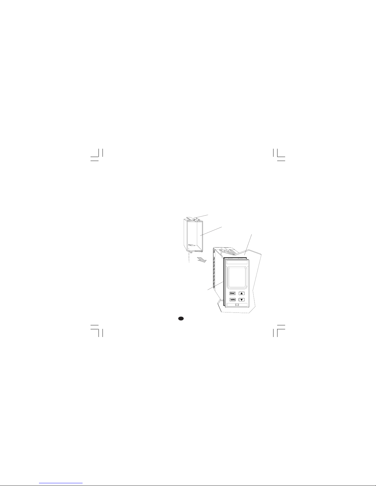
panel
screw
screw
gasket
Fig. 1
MOUNTING REQUIREMENTSMOUNTING REQUIREMENTS
MOUNTING REQUIREMENTSMOUNTING REQUIREMENTS
MOUNTING REQUIREMENTS
Select a mounting location having the following
characteristics:
1) it should be easy accessible also on the rear
side.
2) there is no vibrations or impact
3) there are no corrosive gases (sulphuric gas,
ammonia, etc.).
4) there are no water or other fluid (i.e. condense)
5) the ambient temperature is in accordance with
the operative temperature of the instrument
(from 0 to 50 °C).
6) the relative humidity is in accordance with the
instrument specifications ( 20% to 85 % non
condensing).
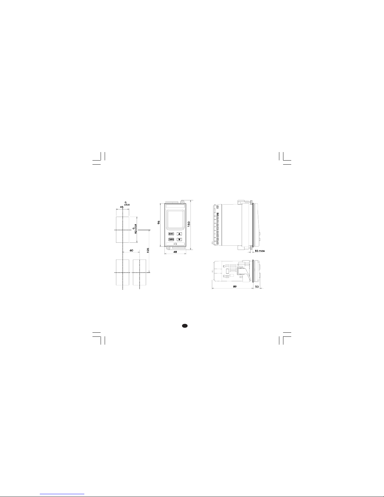
The instrument can be mounted on a panel up to
15 mm thick with a square cutout of 45 x 92 mm.
For outline and cutout dimensions refer to Fig. 2.
The surface texture of the panel must be better
than 6,3 µmm.
The instrument is shipped with rubber panel
gasket (50 to 60 Sh).
To assure the IP65 and NEMA 4 protection, insert
the panel gasket between the instrument and the
panel as shown in fig. 1.
While holding the instrument against the panel
proceed as follows:
1) insert the instrument through the panel gasket,
2) insert the instrument, with the panel gasket,
through the panel cut out,
3) while pressing the instrument firmly against the
panel, insert the mounting bracket and slide it
up to the end of the case,
4) with a screwdriver, turn the screws with a
torque between 0.3 and 0.4 Nm,
5) Make sure you cannot move the case within
the cut out otherwise you do not have a NEMA
4X/IP65 protection.
bracket
Page 5
2
GBGB
GBGB
GB
DIMENSIONS AND PANEL CUT OUTDIMENSIONS AND PANEL CUT OUT
DIMENSIONS AND PANEL CUT OUTDIMENSIONS AND PANEL CUT OUT
DIMENSIONS AND PANEL CUT OUT
Fig. 2
Page 6
3
GBGB
GBGB
GB
WIRING GUIDELINESWIRING GUIDELINES
WIRING GUIDELINESWIRING GUIDELINES
WIRING GUIDELINES
Connections are to be made with the instrument
housing installed in its proper location.
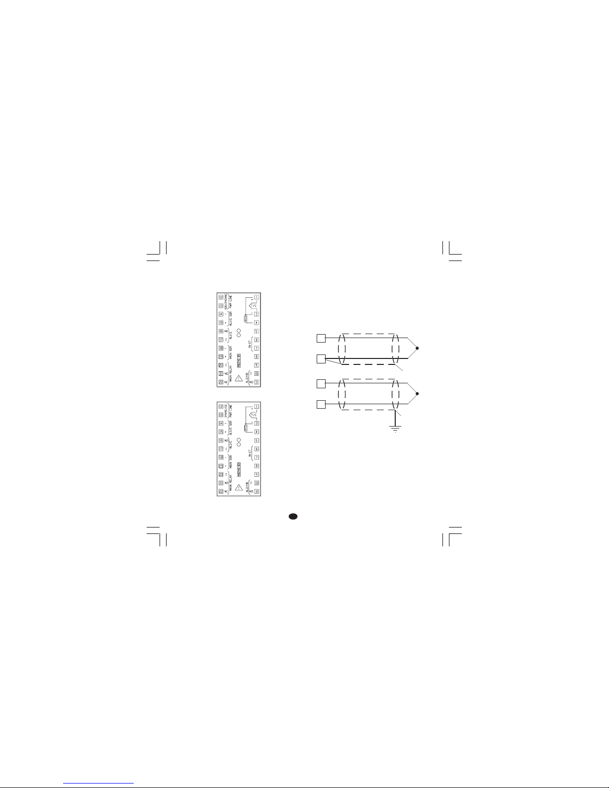
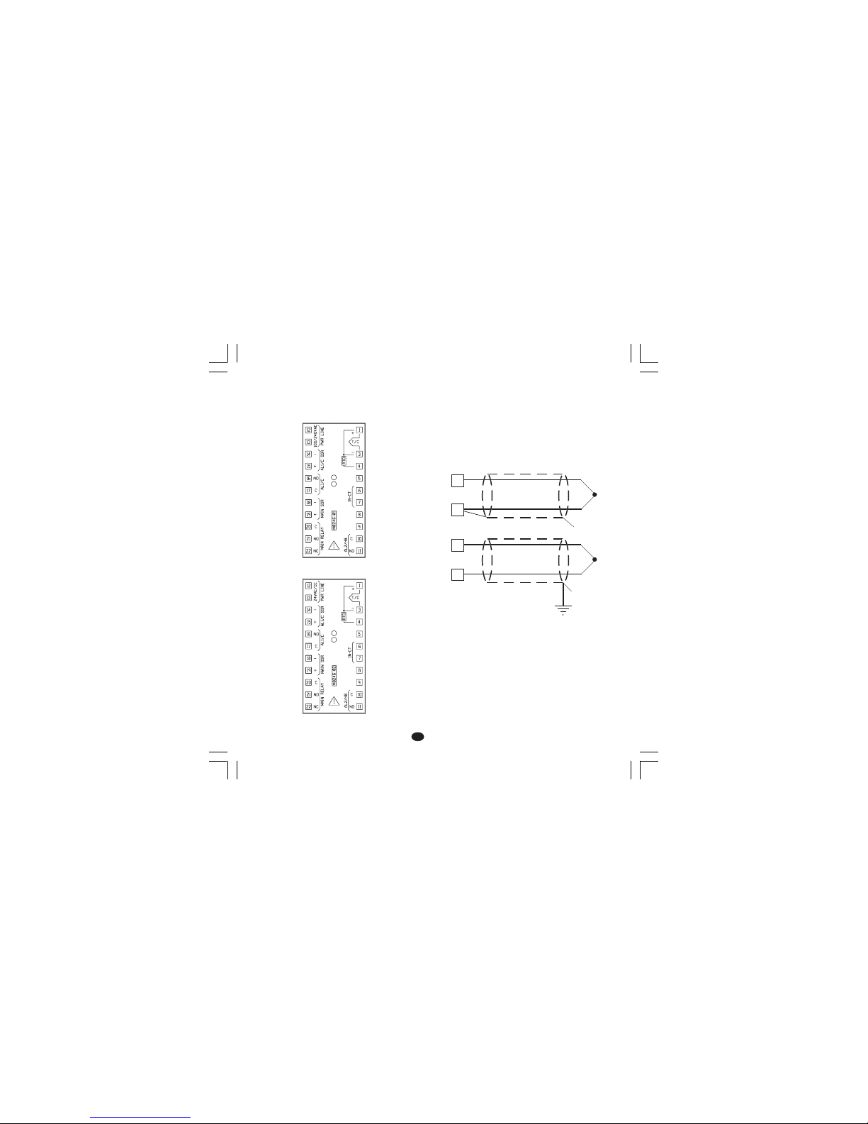
Fig. 3.A TERMINAL BLOCK (for 100/240 V AC
models)
Fig. 3.B TERMINAL BLOCK (for 24 V AC/DC
models)
A) MEASURING INPUTA) MEASURING INPUT
A) MEASURING INPUTA) MEASURING INPUT
A) MEASURING INPUT
NOTENOTE
NOTENOTE
NOTE: Any external components (like zener
barriers etc.) connected between sensor and
input terminals may cause errors in measurement
due to excessive and/or not balanced line
resistance or possible leakage currents.
THERMOCOUPLE INPUTTHERMOCOUPLE INPUT
THERMOCOUPLE INPUTTHERMOCOUPLE INPUT
THERMOCOUPLE INPUT
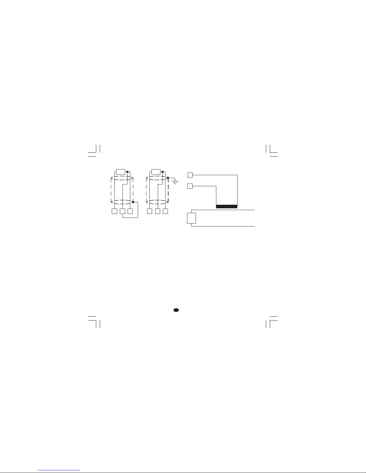
Fig. 4 THERMOCOUPLE INPUT WIRING
NOTENOTE
NOTENOTE
NOTE:
1) Don’t run input wires together with power cables.
2) For TC wiring use proper compensating cable
preferably shielded
3) If shielded cable is used, it should be grounded
at one point only.
1
3
+
_
1
3
+
_
Shield
Shield
Page 7
4
GBGB
GBGB
GB
RTD INPUTRTD INPUT
RTD INPUTRTD INPUT
RTD INPUT
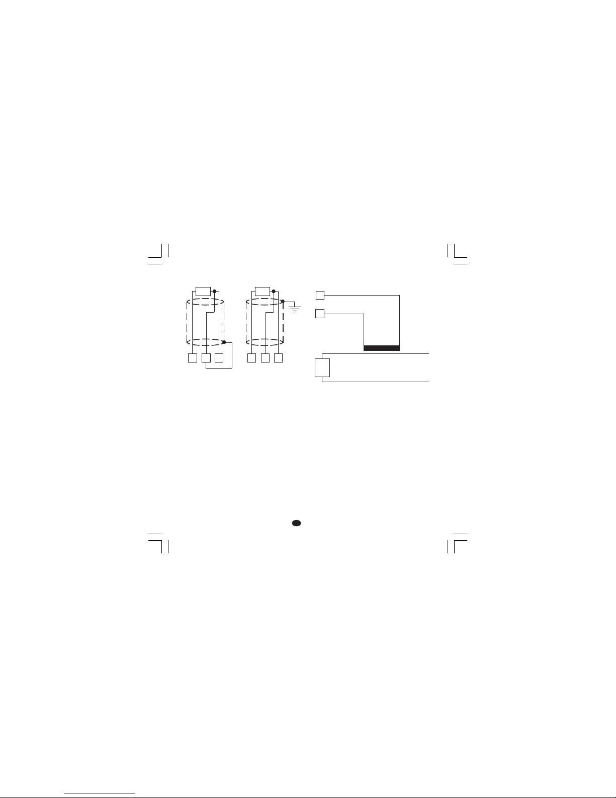
Fig. 5 RTD INPUT WIRING
NOTENOTE
NOTENOTE
NOTE:
1) Don’t run input wires together with power cables.
2) Pay attention to the line resistance; a high line
resistance (higher than 20 Ω/wire) may cause
measurement errors.
3) If shielded cable is used, it should be grounded
at one point only.
4) The resistance of the 3 wires must be the
same.
B) CURRENT TRANSFORMER INPUTB) CURRENT TRANSFORMER INPUT
B) CURRENT TRANSFORMER INPUTB) CURRENT TRANSFORMER INPUT
B) CURRENT TRANSFORMER INPUT
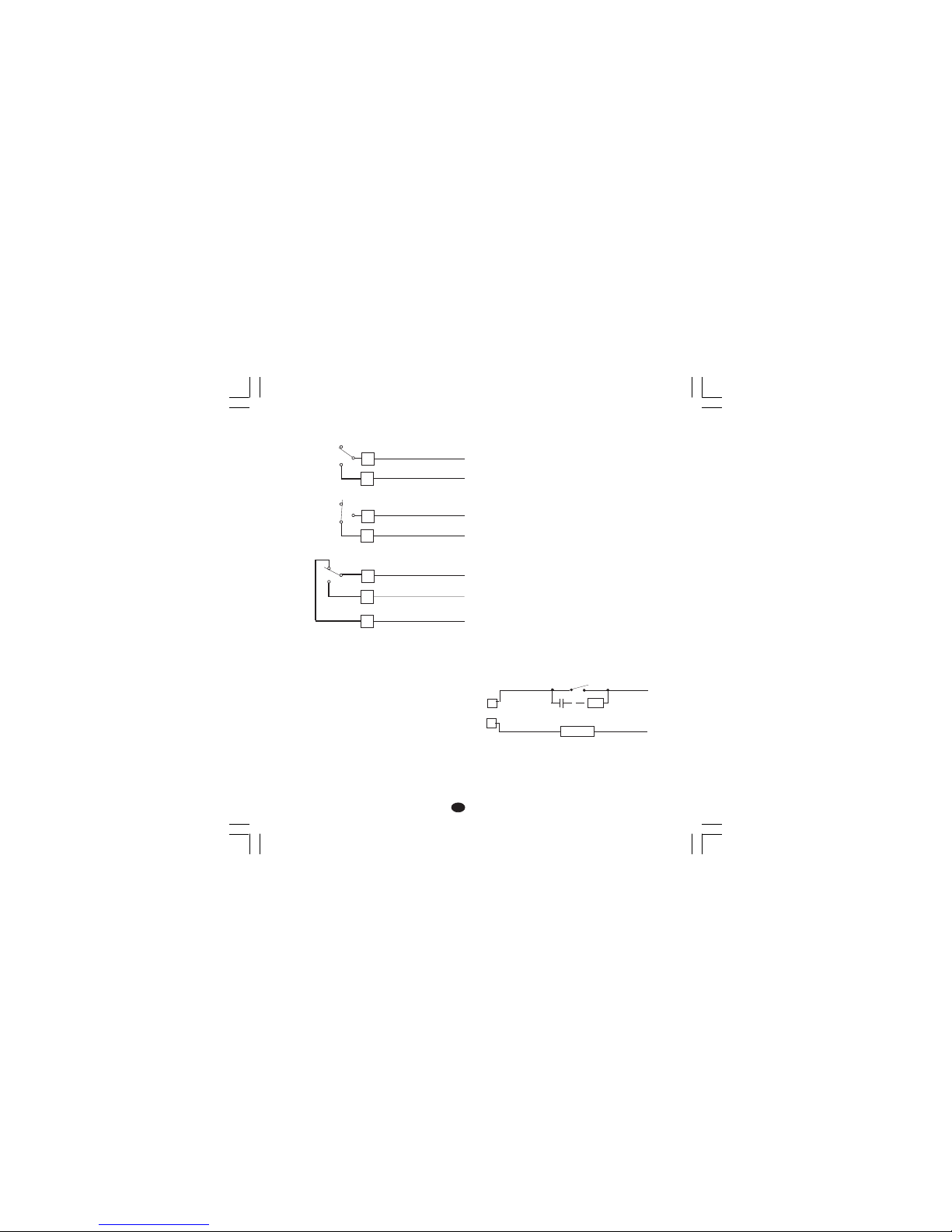
Fig. 6 CURRENT TRANSFORMER INPUT
WIRING
Note:
1) The input impedance is equal to 10 Ω.
2) the maximum input current is equal to 50 mA
(50 / 60 Hz).
4
RTD
13 4
RTD
13
6
7
Current
transformer
Load
Page 8
5
GBGB
GBGB
GB
3) Use copper conductors only.
4) Don’t run input wires together with power cables.
5) Relay output and SSR drive output are both
available. When a relay output is desired it is
necessary to enable the SSR output and
viceversa (see chapter "Preliminary hardware
settings").
The following recommendations avoid serious
problems which may occur, when using relay
output for driving inductive loads.
INDUCTIVE LOADSINDUCTIVE LOADS
INDUCTIVE LOADSINDUCTIVE LOADS
INDUCTIVE LOADS
High voltage transients may occur when switching
inductive loads.
Through the internal contacts these transients
may introduce disturbances which can affect the
performance of the instrument.
The internal protection (varistor) assures a correct
protection up to 0.5 A of inductive component but
the OUT 1 NC contact and out 3 are not
protected.
The same problem may occur when a switch is
used in series with the internal contacts as shown
in Fig. 8.
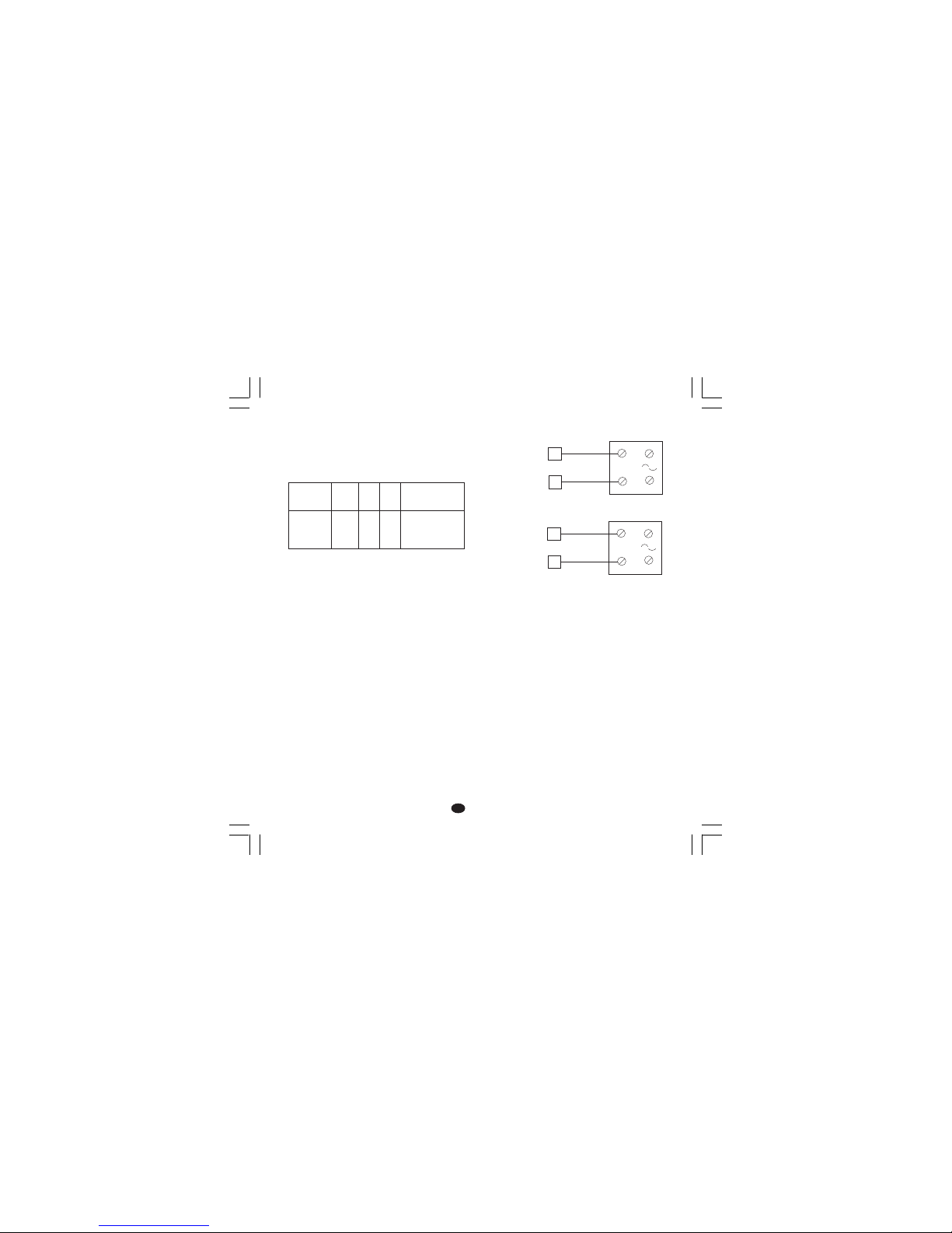
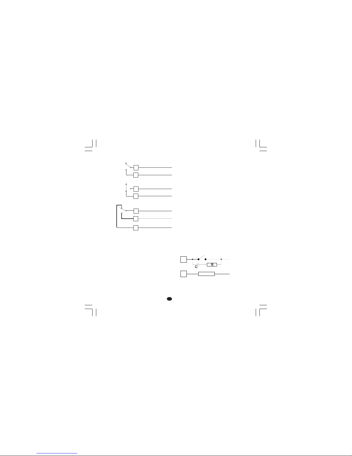
Fig. 8 EXTERNAL SWITCH IN SERIES WITH
THE INTERNAL CONTACT
C) RELAY OUTPUTSC) RELAY OUTPUTS
C) RELAY OUTPUTSC) RELAY OUTPUTS
C) RELAY OUTPUTS
Fig. 7 RELAY OUTPUT WIRINGS
The output 2 and the NO contact of the output 1 are
protected, by varistor, from inductive load with an
inductive component up to 0,5 A.
The rating of the out 1 contact is equal to 3A/250
V AC on resistive load.
The rating of the out 2 and 3 contacts is equal to
2A/250 V AC on resistive load.
The number of operations is 1 x 10
5
at specified
rating.
NOTESNOTES
NOTESNOTES
NOTES:
1) To avoid electric shock, connect power line at
the end of the wiring procedure.
2) For power connections use No 16 AWG or larger
wires rated for at last 75 °C.
21
OUT 1
20
C
NO
22
NC
10
11
AL2/HBD
(OUT 3)
C - OUT 3
NO - OUT 3
16
17
AL1/COOL
(OUT 2)
OUT 2
C - OUT 2
NO/NC
[see Fig.11 (J303)]
LOAD
R
C
POWER
LINE
Page 9
6
GBGB
GBGB
GB
In these cases it is recommended to install an
additional RC network across the external contact
(or close to the non protected contact of the
instrument) as shown in Fig. 8.
The capacity (C) and resistive (R) values are
shown in the following table.
The cable involved in relay output wiring must be
as far away as possible from input or communication cables.
D) LOGIC OUTPUT FOR SSR DRIVED) LOGIC OUTPUT FOR SSR DRIVE
D) LOGIC OUTPUT FOR SSR DRIVED) LOGIC OUTPUT FOR SSR DRIVE
D) LOGIC OUTPUT FOR SSR DRIVE
Fig. 9 SSR DRIVE OUTPUT WIRING.
These are time proportioning outputs.
Logic level 0Logic level 0
Logic level 0Logic level 0
Logic level 0: Vout < 0.5 V DC.
Logic level 1Logic level 1
Logic level 1Logic level 1
Logic level 1:
- 14 V
+ 20 % @ 20 mA
- 24 V
+ 20 % @ 1 mA.
Maximum current = 20 mA.
NOTESNOTES
NOTESNOTES
NOTES:
1) These outputs are not isolated.
A double or reinforced isolation between instrument output and power supply must be assured
by the external solid state relay.
2) Relay output and SSR drive output are both
available. When a SSR output is desired it is
necessary to enable the relay output and
viceversa (see chapter "Preliminary hardware
settings").
LOAD
(mA)
<40 mA
<150 mA
<0.5 A
C
(µF)
0.047
0.1
0.33
R
(Ω)
100
22
47
P.
(W)
1/2
2
2
OPERATING
VOLTAGE
260 V AC
260 V AC
260 V AC
Solid state relay
Solid state relay
_
+
_
+
_
_
+
+
18
19
14
15
OUT 1
OUT 2
(AL1/Cool.)
Page 10

7
GBGB
GBGB
GB
13
R (S,T)
R (S,T)
N
12
N
Power line
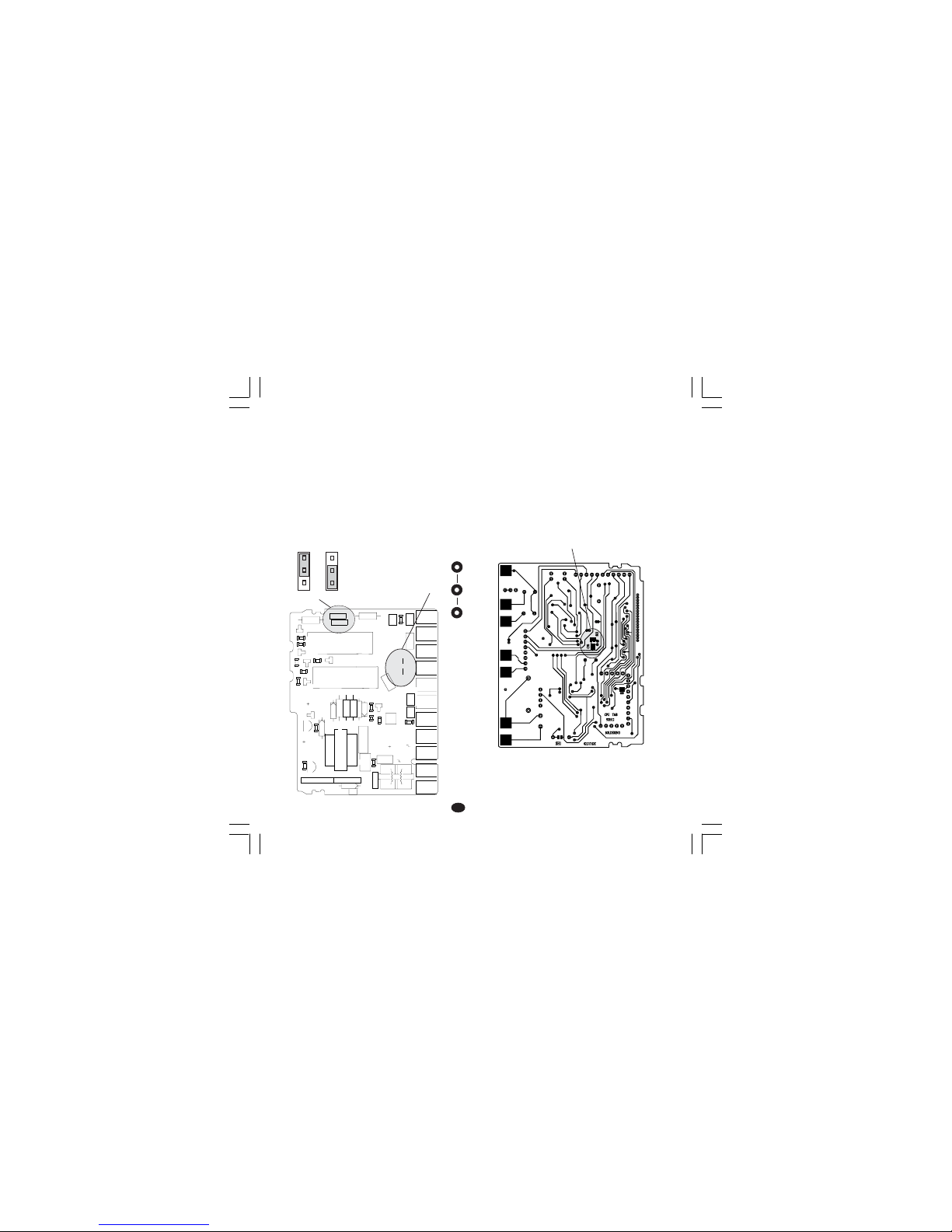
from 100 V to 240 V AC (50/60Hz)
or 24 V AC/DC
E) POWER SUPPLYE) POWER SUPPLY
E) POWER SUPPLYE) POWER SUPPLY
E) POWER SUPPLY
Fig. 10 POWER LINE WIRING
NOTENOTE
NOTENOTE
NOTE:
1) Before connecting the instrument to the power
line, make sure that line voltage corresponds
to the description on the identification label.
2) To avoid electric shock, connect power line at
the end of the wiring procedure.
3) For supply connections use No 16 AWG or larger
wires rated for at last 75 °C.
4) Use copper conductors only.
5) Don’t run input wires together with power cables.
6) For 24 V AC/DC power supply, the input polarity
is a do not care condition.
7) The power supply input has no fuse protection.
Please, provide a fuse type T, 1 A, 250 V
externally.
When fuse is damaged, it is advisable to verify
the power supply circuit, so that it is necessary to
send back the instrument to your supplier.
8) The safety requirements for Permanently
Connected Equipment say:
- a switch or circuit-breaker shall be included in
the building installation;
- It shall be in close proximity to the equipment
and within easy reach of the operator;
- it shall be marked as the disconnecting
device for the equipment.
NOTENOTE
NOTENOTE
NOTE: a single switch or circuit-breaker can drive
more than one instrument.
9) When a neutral line is present, connect it to
terminal 12.
Page 11
8
GBGB
GBGB
GB
PRELIMINARY HARDWAREPRELIMINARY HARDWARE
PRELIMINARY HARDWAREPRELIMINARY HARDWARE
PRELIMINARY HARDWARE
SETTINGSSETTINGS
SETTINGSSETTINGS
SETTINGS
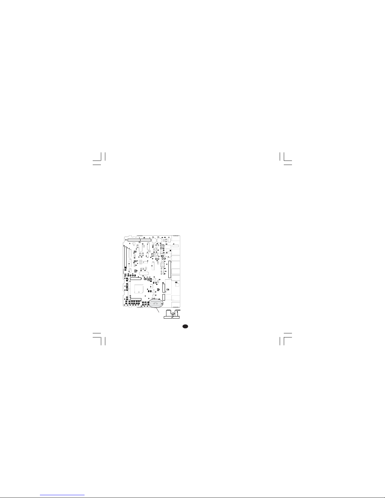
1) Remove the instrument from its case.
2) For out 1 and 2 it is possible to select the
desired output type by setting the J304 and J305
jumpers.
J304 (AL1, Cool.) 1-2 = SSR 2-3 = Relay
J305 (OUT 1) 1-2 = SSR 2-3 = Relay
3) For out 2 it is possible to select the used relay
contact (NO or NC) by setting J303 jumper.
J303 (AL1, Cool.) 1-2 = Out NO 2-3 = Out NC
Note Note
Note Note
Note : J303 is a soldering jumper and it is located
on the soldering side of the card.
Fig 11
OPEN INPUT CIRCUITOPEN INPUT CIRCUIT
OPEN INPUT CIRCUITOPEN INPUT CIRCUIT
OPEN INPUT CIRCUIT
These device are capable to detect leads break
for TC and RTD inputs. For RTD input it shows
this status as an overrange condition.
For thermocouple input only, it is possible, to
select the overrange indication (standard) by
closing CH2 and opening SH2 or underrange
indication by closing SH2 and opening CH2.
SH2 and CH2 are located on the soldering side of
the CPU card (see fig.12).
Fig. 12
1
1
1
23
4
+
-
+
B
C
E
I
1
3
4
7
1
1
XY00
I
1
2
3
12
3
45
12
345
J301
J302
L305
R301
R303
D
3
0
5
C308
C306
C307
R305
C312
C310
D307
R308
C309
PZ12
PZ13
PZ14
PZ15
PZ16
PZ19
PZ20
PZ21
PZ22
R307
R306
Q302
U302
TR301
J304
J305
Y301
D306
D308
D304
U301
PZ18
PZ17
C301
C
3
0
4
J303
C303
C311
C302
C305
C314
C313
L304
L301
L303
L302
R309
R310
R312
R314
R311
R302
R304
R313
Q303
Q305
D302
Q301
Q304
D301
D310
K302
K301
J 303
1
1
3
J304 J305
CH2
SH2
Page 12
9
GBGB
GBGB
GB
GENERAL NOTES for configuration.GENERAL NOTES for configuration.
GENERAL NOTES for configuration.GENERAL NOTES for configuration.
GENERAL NOTES for configuration.
FUNC = This will memorize the new value of
the selected parameter and go to the
next parameter (increasing order).
SMRT = This will scroll back the parameters
without memorization of the new value.
= This will increase the value of the
selected parameter
= This will decrease the value of the
selected parameter.
CONFIGURATION PROCEDURECONFIGURATION PROCEDURE
CONFIGURATION PROCEDURECONFIGURATION PROCEDURE
CONFIGURATION PROCEDURE
1) Remove the instrument from its case.
2) Set the internal switch V2 in open condition
Fig.13
3) Re-insert the instrument..
4) Switch the instrument “ON”.
The display will show COnF.
NOTE NOTE
NOTE NOTE
NOTE : If “CAL” indication is displayed, press
immediately the push-button to return to the
configuration procedure.
5) Push the FUNC push-button.
The instrument will show on the lower display
the parameter code and on the upper display
the actual parameter value.
P1 - Input type and standard rangeP1 - Input type and standard range
P1 - Input type and standard rangeP1 - Input type and standard range
P1 - Input type and standard range
0 = TC type L range 0 / +800 °C
1 = TC type J range 0 / +800 °C
2 = TC type K range 0 / +999 °C
3 = TC type N range 0 / +999 °C
4 = RTD type Pt 100 range -199 / +500 °C
5 = RTD type Pt 100 range -19.9 /+99.9 °C
6 = TC type T range 0 / +400 °C
8 = TC type L range 0 / +999 °F
9 = TC type J range 0 / +999 °F
10 = TC type K range 0 / +999 °F
11 = TC type N range 0 / +999 °F
12 = RTD type Pt 100 range -199 / +999 °F
13 = TC type T range 0 / +752 °F
P2 = Initial scale valueP2 = Initial scale value
P2 = Initial scale valueP2 = Initial scale value
P2 = Initial scale value
Not present when P1 = 5
Initial scale value used by the PID algorithm to
calculate the input span.
P2 is programmable within the input span
selected by P1.
When P2 has been modified, the instrument
assignes to the rL parameter the new P2 value.
V2
Page 13

10
GBGB
GBGB
GB
P3 = Full scale valueP3 = Full scale value
P3 = Full scale valueP3 = Full scale value
P3 = Full scale value
Not present when P1 = 5
Full scale value used by the PID algorithm to
calculate the input span.
P3 is programmable within the input span
selected by P1.
When P3 has been modified, the instrument
assignes to the rH parameter the new P3 value.
NOTENOTE
NOTENOTE
NOTE: the minimum input span (P3 - P2) is
- 300 °C or 600 °F for TC input
- 100 °C or 200 °F for RTD input.
P4 = Output configurationP4 = Output configuration
P4 = Output configurationP4 = Output configuration
P4 = Output configuration
H = heating
HC = heating/cooling
P5 = Main output typeP5 = Main output type
P5 = Main output typeP5 = Main output type
P5 = Main output type
rEL = Relay output.
SSr = SSR output.
NOTENOTE
NOTENOTE
NOTE:
Setting P5 = rEL, the C parameter will be
automatically set to 20 s.
Setting P5=SSr, the C parameter will be
automatically set to 2 s.
P6 = Cooling output typeP6 = Cooling output type
P6 = Cooling output typeP6 = Cooling output type
P6 = Cooling output type
Available only when P4 = HC
AIr = air
OIL = oil
H2O = water
NOTENOTE
NOTENOTE
NOTE:
Setting P6 = Air, the C2 parameter will be
automatically set to 10 s
and rC parameter will be
set to 1.00.
Setting P6=OiL, the C2 parameter will be au-
tomatically set to 4 s and rC
parameter will be set to 0.80.
Setting P6=H2O, the C2 parameter will be au-
tomatically set to 2 s and rC
parameter will be set to 0.40.
P7 = Alarm 1P7 = Alarm 1
P7 = Alarm 1P7 = Alarm 1
P7 = Alarm 1
Available only when P4 = H.
0 = Not provided
1 = Process alarm
2 = Band alarm
3 = Deviation alarm
P8 = Alarm 1 operative modeP8 = Alarm 1 operative mode
P8 = Alarm 1 operative modeP8 = Alarm 1 operative mode
P8 = Alarm 1 operative mode
Available only when P7 is different from 0 and
P4 = H.
H.A = high alarm (outside band) with automatic
reset
L.A = low alarm (inside band) with automatic reset
H.L= high alarm (outside band) with manual reset
L.L= low alarm (inside band) with manual reset
P9 = Stand by (mask) of the alarm 1P9 = Stand by (mask) of the alarm 1
P9 = Stand by (mask) of the alarm 1P9 = Stand by (mask) of the alarm 1
P9 = Stand by (mask) of the alarm 1
Available only when P7 is different from 0 and
P4 = H.
OFF = stand by (mask) disabled
ON = stand by (mask) enabled
NOTENOTE
NOTENOTE
NOTE: the alarm stand by function allows to
disable the alarm indication at instrument start up
or, for band and deviation alarms, after a set point
modification.
The alarm will be automatically reactivated when
the initial alarm condition disappears.
Page 14

11
GBGB
GBGB
GB
P10 = Alarm 2P10 = Alarm 2
P10 = Alarm 2P10 = Alarm 2
P10 = Alarm 2
0 = Not provided
1 = Process alarm
2 = Band alarm
3 = Deviation alarm
Alarm 2 and HBD functions are in OR condition
on the output 3 (see P16 parameter).
P11 = Alarm 2 operative mode and reset of theP11 = Alarm 2 operative mode and reset of the
P11 = Alarm 2 operative mode and reset of theP11 = Alarm 2 operative mode and reset of the
P11 = Alarm 2 operative mode and reset of the
HBD alarm.HBD alarm.
HBD alarm.HBD alarm.
HBD alarm.
Available only when P10 is different from 0 or P16
is different from OFF.
H.A = high alarm (outside band) with
automatic reset
L.A = low alarm (inside band) with automatic reset
H.L= high alarm (outside band) with manual reset
L.AL= low alarm (inside band) with manual reset
NOTENOTE
NOTENOTE
NOTE: The HBD alarm is a low alarm but it
assumes the same reset type selected for
alarm 2.
P12 = Stand by (mask) of the alarm 2P12 = Stand by (mask) of the alarm 2
P12 = Stand by (mask) of the alarm 2P12 = Stand by (mask) of the alarm 2
P12 = Stand by (mask) of the alarm 2
Available only when P10 is different from 0.
OFF = stand by (mask) disabled
ON = stand by (mask) enabled
For other details see P9 parameter.
P13 = Type of OFFSET applied to theP13 = Type of OFFSET applied to the
P13 = Type of OFFSET applied to theP13 = Type of OFFSET applied to the
P13 = Type of OFFSET applied to the
measured valuemeasured value
measured valuemeasured value
measured value
P13 = 0 the OFFSET (P14) is
constant all over the range.
P13 different from 0P13 is the application point of
the OFFSET selected by P14
parameter.
NOTENOTE
NOTENOTE
NOTE: the P13 and P14 parameters do not
modify the measuring or read-out limits of the
instrument so that when one of this limit has been
exceeded, the instrument will show an out of
range condition.
P14 = OFFSET valueP14 = OFFSET value
P14 = OFFSET valueP14 = OFFSET value
P14 = OFFSET value
When P13 = 0, P 14 is programmable, in
engineering units, from -20% to
+ 20% of the input span (see
P1).
When P13 ≠ 0 P14 is programmable, in
engineering units, from -20% to
+ 20% of the P13 value.
NOTENOTE
NOTENOTE
NOTE: the P14 parameter can not be set lower
than -199 units.
P15 = Threshold of the “Soft Start” function.P15 = Threshold of the “Soft Start” function.
P15 = Threshold of the “Soft Start” function.P15 = Threshold of the “Soft Start” function.
P15 = Threshold of the “Soft Start” function.
Threshold value, in engineering units, used by the
instrument for automatic enabling of the "soft
start" function (timed output power limiting).
At instrument start up, if the measured value is
lower than the programmed threshold value, the
instrument will automatically enable the output
power limiter (see OLH parameter) and it
maintains this limit for a time programmed by tOL
parameter.
At instrument start up, if the tOL parameter is
equal to "InF", the P15 setting has no effect.
P13 = 0
Readout.
Adjusted
curve
Input
P14
Real
curve
P13
Readout.
P14
Input
Real
curve
Adjusted
curve
Page 15

12
GBGB
GBGB
GB
P16 =P16 =
P16 =P16 =
P16 =
Measure of the current consumed byMeasure of the current consumed by
Measure of the current consumed byMeasure of the current consumed by
Measure of the current consumed by
the load driven by the main outputthe load driven by the main output
the load driven by the main outputthe load driven by the main output
the load driven by the main output
(HBD)(HBD)
(HBD)(HBD)
(HBD)
OFF = measure disabled
n.O. = measure enabled during the ON period
(logic status 1 for SSR output or contact
NO for relay output)
n.C. = measure enabled during the OFF period
(logic status 0 for SSR output or contact
NC for relay output)
P17 =P17 =
P17 =P17 =
P17 =
Full scale of the current transformer.Full scale of the current transformer.
Full scale of the current transformer.Full scale of the current transformer.
Full scale of the current transformer.
Available only when P16 is different from OFF.
10 = 10 A (resolution: 0.1 A)
25 = 25 A (resolution: 1 A)
50 = 50 A (resolution: 1 A)
100 = 100 A (resolution: 1 A)
P18 = Safety lockP18 = Safety lock
P18 = Safety lockP18 = Safety lock
P18 = Safety lock
0 = device unlocked. All the parameters can be
modified
1 = device locked. No one parameters can be
modified exception made for SP.
From 2 to 499 = during operative mode, SP
parameter can be modified and
this number allows to enable/
disable the modification of all the
other parameters.
From 500 to 999 = SP, A1 and A2 parameters
can be modified and this number
allows to enable/disable the
modification of all the other
parameters.
NOTENOTE
NOTENOTE
NOTE: After FUNC push-button pressure it will be
impossible to display this value again. If you don't
remember the old key, set a new value.
The configuration procedure is completed and the
instrument will show "
-.-.-." on both displays.
When it is desired to end the configuration
procedure push the FUNC push-button; the
display will show "COnF".
When it is desired to access to the advanced
configuration parameter, proceed as follows:
1) using and push-button set the 217 code.
2) push the FN push-button; the instrument will
start the auxiliary configuration procedure and
it will show the following additional parameters.
P19 - Main output actionP19 - Main output action
P19 - Main output actionP19 - Main output action
P19 - Main output action
Available only when P4 = H.
r = Reverse (heating)
d = direct (cooling)
NoteNote
NoteNote
Note : when P4 = HC, this parameter is
equal to "r".
P21 - Alarm 1 output actionP21 - Alarm 1 output action
P21 - Alarm 1 output actionP21 - Alarm 1 output action
P21 - Alarm 1 output action
Available only when P7 is different from 0 and P4
is equal to H.
r = reverse (relay de-energized in alarm
condition).
d = Direct (relay energized in alarm condition)
t
Input
t
Output
t
Input
t
Output
Reverse Direct
Page 16

13
GBGB
GBGB
GB
P22 - Alarm 2 output actionP22 - Alarm 2 output action
P22 - Alarm 2 output actionP22 - Alarm 2 output action
P22 - Alarm 2 output action
Available only when P10 is different from 0 and
P16 is different from "OFF".
r = reverse (relay de-energized in alarm
condition).
d = Direct (relay energized in alarm condition)
P23 - Automatic modification of the "relativeP23 - Automatic modification of the "relative
P23 - Automatic modification of the "relativeP23 - Automatic modification of the "relative
P23 - Automatic modification of the "relative
cooling gain"cooling gain"
cooling gain"cooling gain"
cooling gain"
Available only when P4=HC.
OFF = The SMART function will
NOT NOT
NOT NOT
NOT modify
the "relative cooling gain" parameter
value.
ON = The SMART function will modify the
"relative cooling gain" parameter value.
P24 - Control output maximum rate of riseP24 - Control output maximum rate of rise
P24 - Control output maximum rate of riseP24 - Control output maximum rate of rise
P24 - Control output maximum rate of rise
This parameter allows to set the maximum rate of
rise of the control output.
It is programmable from 1 to 10 % of the output
signal per second.
Setting a value greater then 10%/s the upper
display will blank and no limit is applied.
P25 - Display of the protect parameterP25 - Display of the protect parameter
P25 - Display of the protect parameterP25 - Display of the protect parameter
P25 - Display of the protect parameter
enabling/disabling.enabling/disabling.
enabling/disabling.enabling/disabling.
enabling/disabling.
Available only when P18 is different from 0.
OFF = protected parameter cannot be displayed
ON = protected parameter can be displayed
P26 - SMART function enabling/ disablingP26 - SMART function enabling/ disabling
P26 - SMART function enabling/ disablingP26 - SMART function enabling/ disabling
P26 - SMART function enabling/ disabling
0 = The SMART function is disabled
1 = The SMART function enabling/disabling
is
NOT NOT
NOT NOT
NOT protected by the safety key.
2 = The SMART function enabling/disabling
is protected by the safety key.
P27 - Maximum value of the proportional bandP27 - Maximum value of the proportional band
P27 - Maximum value of the proportional bandP27 - Maximum value of the proportional band
P27 - Maximum value of the proportional band
settable by the SMART functionsettable by the SMART function
settable by the SMART functionsettable by the SMART function
settable by the SMART function
Available only when P26 is different from 0.
This parameter may be programmed from P28 or
P29 value to 99.9.
P28 - Minimum value of the proportional bandP28 - Minimum value of the proportional band
P28 - Minimum value of the proportional bandP28 - Minimum value of the proportional band
P28 - Minimum value of the proportional band
settable by the SMART functionsettable by the SMART function
settable by the SMART functionsettable by the SMART function
settable by the SMART function
Available only when P4=H and P26 is different
from 0.
This parameter may be programmed from 1.0 %
to P27 value.
P29 - Minimum value of the proportional bandP29 - Minimum value of the proportional band
P29 - Minimum value of the proportional bandP29 - Minimum value of the proportional band
P29 - Minimum value of the proportional band
settable by the SMART function in heating/settable by the SMART function in heating/
settable by the SMART function in heating/settable by the SMART function in heating/
settable by the SMART function in heating/
cooling control onlycooling control only
cooling control onlycooling control only
cooling control only
Available only when P4=HC and P26 is different
from 0.
This parameter may be programmed from 1.5 %
to P27 value.
P30 - Minimum value of integral time settableP30 - Minimum value of integral time settable
P30 - Minimum value of integral time settableP30 - Minimum value of integral time settable
P30 - Minimum value of integral time settable
by SMART function.by SMART function.
by SMART function.by SMART function.
by SMART function.
Available only when P26 is different from 0.
This parameter may be programmed from 00.1
(mm.s) to 02.0 (mm.s).
P31 - Extension of the anti-reset-wind upP31 - Extension of the anti-reset-wind up
P31 - Extension of the anti-reset-wind upP31 - Extension of the anti-reset-wind up
P31 - Extension of the anti-reset-wind up
Range: from -30 to +30 % of the proportional
band.
NOTENOTE
NOTENOTE
NOTE: a positive value increases the high limit of
the anti-reset-wind up (over set point) while a
negative value decreases the low limit of the antireset-wind up (under set point).
The auxiliary configuration is finished and the
instrument will show "CnF" on the upper display.
Page 17

14
GBGB
GBGB
GB
OPERATIVE MODEOPERATIVE MODE
OPERATIVE MODEOPERATIVE MODE
OPERATIVE MODE
1) Remove the instrument from its case.
2) Set the V2 jumper (see fig. 13) in close
condition.
3) Re-insert the instrument.
4) Switch on the instrument.
The upper display will show the measured value
while the lower display will show the programmed
set point (we define this display condition as
“normal display mode”).
NoteNote
NoteNote
Note: When a ramp is applied to the set point value
(see rP parameter), the displayed set point
value may be different from the operative set
point.
When the HBD function is configured, the control
output is enabled and the instrument is in normal
display mode, pushing the push-button the
lower display will show the current, followed by
the "A" symbol, consumed by the load driven by
the main output.
NOTENOTE
NOTENOTE
NOTE: the time out has no effect on this
indication.
When it is desired to come back to the normal
display mode, push the push-button again.
SMART functionSMART function
SMART functionSMART function
SMART function
The SMART algorithm is a NEW self-tuning
function of the instrument. It is used by the
instrument to calculate and set automatically the
control parameters.
The SMART algorithm may be ever operative; in
this case it will adapt continuously the control
parameter in order to perform the best control
action.
To start "SMART" function, depress the SMRT
push-button for more than 1.5 seconds when the
instrument is in NORMAL DISPLAY MODE, the
SMRT indicator will start blinking or lighting
according to the special function performing.
When it is desired to disable the SMART function,
push the SMRT push-button again, the SMRT
indicator will turn to OFF.
NOTESNOTES
NOTESNOTES
NOTES:
1) During the SMART function operation, the
relative cooling gain (if present) is limited within
the following ranges:
Cooling element range
Air 0.85 to 1.00
OIL 0.80 to 0.90
H
2
O 0.30 to 0.60
2) The SMART function use a derivative action
equal to 1/4 of the integral action.
3) The limits of the proportional band and of the
integral time settable by the SMART function
are programmed by P27, P28, P29 and P30
parameter.
4) The enabling/disabling of the SMART function
may be under safety key protection.
5) When SMART function is enabled, it is
impossible to modify the Pb, ti and td
parameter; for rC parameter see P23
parameter.
Page 18

15
GBGB
GBGB
GB
HEATER BREAK DOWN ALARMHEATER BREAK DOWN ALARM
HEATER BREAK DOWN ALARMHEATER BREAK DOWN ALARM
HEATER BREAK DOWN ALARM
This alarm allows to verify, continuously, the
current consumed by the load driven by the main
output and generates an alarm condition when
this current is lower than a programmable
threshold.
To display the main load consumption, push the
push-button when the instrument is in
NORMAL DISPLAY MODE.
The upper display will show the measured value
while the lower display will show the main load
consumption (in Ampere) followed by the
engineering unit (A).
To come back to the normal display mode, push
the push-button.
When an alarm condition is detected, the LED
AL2/HB will be flashing and the relay of the out 3
(alarm 2 OR heater break down alarm) will be
activated.
OUTPUT POWER OFFOUTPUT POWER OFF
OUTPUT POWER OFFOUTPUT POWER OFF
OUTPUT POWER OFF
The TMS allows to turn OFF manually the output
signal in order to stop the control (the instrument
will operate as an indicator only).
To turn OFF the output signal proceed as follows:
1) push and maintain the pressure on the
push-button
2) push FUNC push-button.
3) Maintaining the pressure on both push-buttons
for more than 3 seconds; the lower display will
show "OFF" and the output signal will be
inhibited.
When it is desired to come back to the normal
control, repeat the actions 1, 2 and 3; the
instrument goes automatically to the NORMAL
DISPLAY MODE.
NOTE: NOTE:
NOTE: NOTE:
NOTE: 1)The instrument memorizes the output
status.
2) If the output is turned OFF when the
SMART function was performing the first
part of the algorithm (LED SMRT is
flashing), the SMART function will be
aborted and when the instrument comes
back to the normal control, the SMART
function will be disabled.
If the output is turned OFF when the
SMART function was performing the
adaptive part of the algorithm (LED
SMRT is lit), the SMART function will be
stopped and, when the instrument
comes back to the normal control, the
smart function also will be activated.
Page 19

16
GBGB
GBGB
GB
DIRECT ACCESS TO THE SET POINTDIRECT ACCESS TO THE SET POINT
DIRECT ACCESS TO THE SET POINTDIRECT ACCESS TO THE SET POINT
DIRECT ACCESS TO THE SET POINT
MODIFICATIONMODIFICATION
MODIFICATIONMODIFICATION
MODIFICATION
The instrument allows to modify the set point
value without to use the FUNC push-button.
When a rapid set point modification is required,
proceed as follows:
1) Pushing, for more than 3 seconds, the or
push-button; the set point value, shown on
the lower display, will start to change.
2) Using the and push-buttons, it is
possible to set the desired value.
3) When the desired value is reached, do not
push any push-button for more than 3
seconds, the new set point will become
operative after 3 seconds from the last pushbutton pressure.
If, during this procedure, it is desired to lose the
new value, push the FUNC push-button; the
instrument automatically returns to the normal
display mode without to memorize the new set
point.
LAMP TESTLAMP TEST
LAMP TESTLAMP TEST
LAMP TEST
When it is desired to verify the display efficiency,
push and FUNC push-buttons. The instrument
will turn ON, with a 50 % duty cycle, all the LED
of the display (we define this function "LAMP
TEST").
No time out is applied to the LAMP TEST.
When it is desired to come back to the normal
display mode, push and FUNC push-buttons
again.
No other keyboard function is available during
LAMP TEST.
OPERATIVE PARAMETERSOPERATIVE PARAMETERS
OPERATIVE PARAMETERSOPERATIVE PARAMETERS
OPERATIVE PARAMETERS
Operative parameter modificationOperative parameter modification
Operative parameter modificationOperative parameter modification
Operative parameter modification
Push the FUNC push-button, the lower display
will show the code while the upper display will
show the value or the status (ON or OFF) of the
selected parameter.
By or push-button it is possible to set the
desired value or the desired status.
Pushing the FUNC push-button, the instrument
memorizes the new value (or the new status) and
goes to the next parameter.
A pressure of the SMRT push-button allows to come
back to the previous parameter without to memorize
the new set of the actual parameter.
Some parameters may be not visualized according
to the specific instrument configuration.
NOTENOTE
NOTENOTE
NOTE: 1) If, during operative parameter
modification, no push-button is
pressed for more than 10 seconds,
the instrument reverts automatically
to the “normal display mode” without
to memorize the last parameter
setting.
2) The instrument do not display all
parameter but it select the
parameter in accordance with:
a) the instrument configuration
b) P25 setting
c) the proportional band setting.
Page 20

17
GBGB
GBGB
GB
Param.Description
SP
Main set pointMain set point
Main set pointMain set point
Main set point
Range: from rL to rH.
n.rS
Manual reset of the alarmsManual reset of the alarms
Manual reset of the alarmsManual reset of the alarms
Manual reset of the alarms
This parameter is available only when one
alarm with manual reset has been
programmed.
Set ON and push the FUNC push-button
to reset the alarms.
nnn
Software key for parameter protectionSoftware key for parameter protection
Software key for parameter protectionSoftware key for parameter protection
Software key for parameter protection.
This parameter is skipped if P18 = 0 or 1.
The instrument will shows the safety key
status:
ON = the instrument is in LOCK condition
OFF = the instrument is in UNLOCK
condition
When it is desired to switch from LOCK to
UNLOCK condition, set a value equal to
P18 parameter
When it is desired to switch from UNLOCK
to LOCK condition, set a value different
from P18 parameter.
A1
Alarm 1 threshold valueAlarm 1 threshold value
Alarm 1 threshold valueAlarm 1 threshold value
Alarm 1 threshold value
This parameters is present if the alarm 1
is configured only.
Ranges:
- From P2 to P3 for process alarm.
- From 0 to 500 units for band alarm.
- From -199 to 500 units for deviation
alarm.
A2
Alarm 2 threshold valueAlarm 2 threshold value
Alarm 2 threshold valueAlarm 2 threshold value
Alarm 2 threshold value
For other details see A1 parameter.
H1
Alarm 1 hysteresisAlarm 1 hysteresis
Alarm 1 hysteresisAlarm 1 hysteresis
Alarm 1 hysteresis
This parameters is present if the alarm 1
is configured only.
Range: From 0.1% to 10.0% of the input
span or 1 LSD.
NoteNote
NoteNote
Note: If the hysteresis of a band alarm is
larger than the alarm band, the instrument
will use an hysteresis value equal to the
programmed band minus 1 digit.
H2
Alarm 2 hysteresisAlarm 2 hysteresis
Alarm 2 hysteresisAlarm 2 hysteresis
Alarm 2 hysteresis
For other details see H1 parameter.
Pb
Proportional band.Proportional band.
Proportional band.Proportional band.
Proportional band.
Range
::
::
: from 1.0 % to 99.9 % of span for
heating output.
From 1.5 % to 99.9 % of span for heating/
cooling output.
When Pb parameter is set to 0, the
instrument performs an ON-OFF control;
the ti, td, IP, C, C2, rC, OLP, OLH and
tOL parameters are skipped and SMART
function is disabled.
NoteNote
NoteNote
Note: When SMART is enabled, the Pb
parameter range is limited by P27, P28 and
P29 parameters.
HS
Hysteresis for ON/OFF control actionHysteresis for ON/OFF control action
Hysteresis for ON/OFF control actionHysteresis for ON/OFF control action
Hysteresis for ON/OFF control action
It is available only when Pb=0.
Range: from 0.1% to 10.0% of the input
span.
ti
Integral timeIntegral time
Integral timeIntegral time
Integral time
"ti" is skipped if Pb=0 (ON/OFF action).
Range: from 00.1 to 20.0 [mm.ss]. Above
this value the display blanks and integral
action is excluded
NoteNote
NoteNote
Note: When SMART is enabled, the minimum value of the integral time is limited by
P30 parameter.
td
Derivative timeDerivative time
Derivative timeDerivative time
Derivative time
"td" is skipped if Pb=0 (ON/OFF action).
Range: from 0.01 to 9.59 m.ss. Setting the
0 value the derivative action is excluded.
NoteNote
NoteNote
Note: When SMART is enabled the td
value will be equal to 1/4 of the integral
time.
Page 21

18
GBGB
GBGB
GB
IP
Integral pre-loadIntegral pre-load
Integral pre-loadIntegral pre-load
Integral pre-load
"IP" is skipped if Pb=0 (ON/OFF action).
Ranges:
- from 0 to 100 % when P4 = H
- from -100 to 100 % when P4 = HC
C
Output 1 cycle timeOutput 1 cycle time
Output 1 cycle timeOutput 1 cycle time
Output 1 cycle time
C is available if Pb parameter is different
from 0 only.
Range: from 1 to 200 s.
C2
Output 2 cycle timeOutput 2 cycle time
Output 2 cycle timeOutput 2 cycle time
Output 2 cycle time
C2 is available only if P4 = "HC" and Pb is
different from 0 only.
Range: from 1 to 200 s.
rC
Relative Cooling gain .Relative Cooling gain .
Relative Cooling gain .Relative Cooling gain .
Relative Cooling gain .
"rC" is skipped if Pb=0 (ON/OFF action)
or P4 = H.
Range: from 0.20 to 1.00
NoteNote
NoteNote
Note: When SMART function is enabled,
the "rC" parameter is limited in accordance to the selected coolant:
- from 0.85 to 1.00 when P6 = AIr
- from 0.80 to 0.90 when P6 = OIL
- from 0.30 to 0.60 when P6 = H2O
OLP
Dead band/Overlap between H/CDead band/Overlap between H/C
Dead band/Overlap between H/CDead band/Overlap between H/C
Dead band/Overlap between H/C
outputsoutputs
outputsoutputs
outputs
"OLP" is skipped if Pb=0 (ON/OFF action)
or P4 = H.
A negative OLAP value shows a dead
band while a positive value shows an
overlap.
Range: from -20 to 50.
rL
Set point low limitSet point low limit
Set point low limitSet point low limit
Set point low limit
Range: from min. range value (P2) to rH.
NoteNote
NoteNote
Note: When P2 has been modified, rL will
be realigned to it.
rH
Set point high limitSet point high limit
Set point high limitSet point high limit
Set point high limit
Range: From rL to full scale value (P3).
NoteNote
NoteNote
Note: When P3 has been modified, rH will
be realigned to it.
rP
Ramp applied to the set point changesRamp applied to the set point changes
Ramp applied to the set point changesRamp applied to the set point changes
Ramp applied to the set point changes
Range: from 1 to 100 digit/min.
Above this value the display shows "inf"
and the transfer will be a step transfer.
OLH
Control output high limitControl output high limit
Control output high limitControl output high limit
Control output high limit
"OLH" is skipped if Pb=0 (ON/OFF action).
Range:
- from 0 to 100 % when P4 = H
- from -100 to 100 % when P4 = HC
tOL
Time duration of the output powerTime duration of the output power
Time duration of the output powerTime duration of the output power
Time duration of the output power
limiterlimiter
limiterlimiter
limiter
"tOL" is skipped if Pb=0 (ON/OFF action).
Range: from 1 to 100 min.
Above this value the display shows "inf"
and the limit will be ever enabled.
NoteNote
NoteNote
Note: The tOL can be modified but the
new value will become operative only at
the next instrument start up.
Hbd
Threshold of the heater break downThreshold of the heater break down
Threshold of the heater break downThreshold of the heater break down
Threshold of the heater break down
alarmalarm
alarmalarm
alarm
"Hbd" is available only when P16 is
different from OFF.
Range: within the current transformer
range (see P17).
Page 22

19
GBGB
GBGB
GB
ERROR MESSAGESERROR MESSAGES
ERROR MESSAGESERROR MESSAGES
ERROR MESSAGES
OVERRANGE, UNDERRANGE AND BURNOUTOVERRANGE, UNDERRANGE AND BURNOUT
OVERRANGE, UNDERRANGE AND BURNOUTOVERRANGE, UNDERRANGE AND BURNOUT
OVERRANGE, UNDERRANGE AND BURNOUT
INDICATIONSINDICATIONS
INDICATIONSINDICATIONS
INDICATIONS
The instrument shows the OVERRANGE
condition with the following indication on the
upper display:
The instrument shows the UNDERRANGE
condition with the following indication on the
upper display:
The sensor leads break can be signalled as:
- for TC input : OVERRANGE or
UNDERRANGE selected by a
solder jumper (see Fig. 12).
- for RTD input : OVERRANGE
Sensor leads short circuit detection:
On RTD input, a special test is provided to signal
OVERRANGE when input resistance is less than
15 ohm (Short circuit sensor detection).
NOTENOTE
NOTENOTE
NOTE: When:
- The instrument is set for one output only and an
OVERRANGE is detected, the OUT 1 turns
OFF (if reverse action) or ON (if direct action).
- The instrument is set for heating/cooling action
and an OVERRANGE is detected, OUT 1 turns
OFF and OUT 2 turn ON.
- The instrument is set for one output only and an
UNDERRANGE is detected, the OUT 1 turns
ON (if reverse action) or OFF (if direct action).
- The instrument is set for heating/cooling action
and an UNDERRANGE is detected, OUT 1
turns ON and OUT 2 turns OFF.
ERRORSERRORS
ERRORSERRORS
ERRORS
Diagnostics are made at instrument switch-on
and during normal mode of operation.
If a fault condition (error) is detected, the lower
display will show the message "Er" while the
upper display shows the relative error code.
ERROR LISTERROR LIST
ERROR LISTERROR LIST
ERROR LIST
100 Write EEPROM error.
150 General hardware error on the CPU card.
200 Tentative to write on protected memory.
201 - 2xx Configuration parameter error. The two
less significant digit’s shown the number
of the wrong parameter (ex. 209 Err show
an Error on P9 parameter)
301 RTD input calibration data error
305 TC input calibration data error
307 RJ calibration data error
310 Current transformer input calibration data
error
400 Control parameters error
500 Auto-zero error.
502 RJ error.
510 Error during calibration procedure.
Page 23

20
GBGB
GBGB
GB
NOTENOTE
NOTENOTE
NOTE
1) When a configuration parameter error is
detected, it is sufficient to repeat the configuration procedure of the specify parameter.
2) If an error 400 is detected, push contemporarily the and push-buttons for loading the
default parameters then repeat control
parameter setting.
3) For all the other errors, contact your supplier.
Page 24
21
GBGB
GBGB
GB
GENERAL INFORMATIONSGENERAL INFORMATIONS
GENERAL INFORMATIONSGENERAL INFORMATIONS
GENERAL INFORMATIONS
GENERAL SPECIFICATIONSGENERAL SPECIFICATIONS
GENERAL SPECIFICATIONSGENERAL SPECIFICATIONS
GENERAL SPECIFICATIONS
CaseCase
CaseCase
Case: PC-ABS black color; self-extinguishing degree: V-0 according to UL 94.
Front protectionFront protection
Front protectionFront protection
Front protection - designed and tested for IP 65 (*)
and NEMA 4X (*) for indoor locations (when panel
gasket is installed).
(*) Test were performed in accordance with CEI 701 and NEMA 250-1991 STD.
InstallationInstallation
InstallationInstallation
Installation: panel mounting by means of mounting
bracket. Instrument removable from case.
Rear terminal block: 21Rear terminal block: 21
Rear terminal block: 21Rear terminal block: 21
Rear terminal block: 21 screw terminals ( screw
M3, for cables from φ 0.25 to φ 2.5 mm
2
or from
AWG 22 to AWG 14 ) with connection diagrams
and safety rear cover.
DimensionsDimensions
DimensionsDimensions
Dimensions: 48 x 96 mm, depth 89 mm (DIN
43700).
WeightWeight
WeightWeight
Weight: 600 g.
Power supplyPower supply
Power supplyPower supply
Power supply:
- 100V to 240V AC 50/60Hz (-15% to + 10% of
the nominal value).
- 24 V AC/DC (
+ 10 % of the nominal value).
Power consumptionPower consumption
Power consumptionPower consumption
Power consumption: 6 VA max.
I
nsulation resistancensulation resistance
nsulation resistancensulation resistance
nsulation resistance: > 100 MΩ according to
IEC 1010-1.
Dielectric strengthDielectric strength
Dielectric strengthDielectric strength
Dielectric strength: 1500 V rms according to IEC
1010-1.
Sampling time: Sampling time:
Sampling time: Sampling time:
Sampling time: 500 ms.
ResolutionResolution
ResolutionResolution
Resolution: 30000 counts.
Accuracy Accuracy
Accuracy Accuracy
Accuracy (@ 25 °C):
+0.2% of the input span +1 °C.
Common mode rejectionCommon mode rejection
Common mode rejectionCommon mode rejection
Common mode rejection: 120 dB at 50/60 Hz.
Normal mode rejection:Normal mode rejection:
Normal mode rejection:Normal mode rejection:
Normal mode rejection: 60 dB at 50/60 Hz.
Electromagnetic compatibility and safetyElectromagnetic compatibility and safety
Electromagnetic compatibility and safetyElectromagnetic compatibility and safety
Electromagnetic compatibility and safety
requirementsrequirements
requirementsrequirements
requirements: This instrument is marked CE.
Therefore, it is conforming to council directives
89/336/EEC (reference harmonized standard
EN 50081-2 and EN 50082-2)and to council
directives 73/23/EEC and 93/68/EEC
(reference harmonized standard EN 61010-1).
Installation categoryInstallation category
Installation categoryInstallation category
Installation category: II
Temperature driftTemperature drift
Temperature driftTemperature drift
Temperature drift: (RJ excluded)
< 400 ppm/°C for RTD input with -19.9/99.9 °C
range and TC type T.
< 200 ppm/°C for all the other ranges.
Operative temperatureOperative temperature
Operative temperatureOperative temperature
Operative temperature: from 0 to 50 °C.
Storage temperature : Storage temperature :
Storage temperature : Storage temperature :
Storage temperature : -20 to +70 °C
HumidityHumidity
HumidityHumidity
Humidity: from 20 % to 85% RH, non condensing.
ProtectionsProtections
ProtectionsProtections
Protections:
1) WATCH DOG circuit for automatic restart.
2) DIP SWITCH for protection against tampering
of configuration and calibration parameters.
INPUTSINPUTS
INPUTSINPUTS
INPUTS
A) A)
A) A)
A)
THERMOCOUPLETHERMOCOUPLE
THERMOCOUPLETHERMOCOUPLE
THERMOCOUPLE
TypeType
TypeType
Type: L, J, K, N, T programmable by front pushbuttons.
Line resistanceLine resistance
Line resistanceLine resistance
Line resistance: max. 100 Ω with error <
+0.1%
of the input span.
BurnoutBurnout
BurnoutBurnout
Burnout: Up or down scale selectable by
soldering jumpers.
Reference junctionReference junction
Reference junctionReference junction
Reference junction: automatic compensation
from 0 to +50 °C.
Reference junction driftReference junction drift
Reference junction driftReference junction drift
Reference junction drift: 0.1 °C/°C.
Input impedanceInput impedance
Input impedanceInput impedance
Input impedance: > 1 MΩ
CalibrationCalibration
CalibrationCalibration
Calibration: according to IEC 584-1 and DIN
43710 - 1977 (TC L)
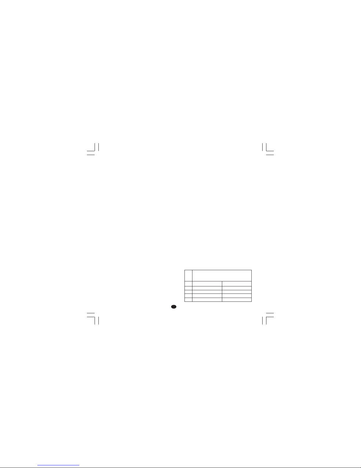
STANDARD RANGE TABLE
TCTC
TCTC
TC
TypeType
TypeType
Type
LL
LL
L
JJ
JJ
J
KK
KK
K
TT
TT
T
NN
NN
N
Measuring rangesMeasuring ranges
Measuring rangesMeasuring ranges
Measuring ranges
0 / + 800 °C
0 / + 800 °C
0 / + 999 °C
0 / + 400 °C
0 / + 999 °C
0 / + 999 °F
0 / + 999 °F
0 / + 999 °F
0 / + 752 °F
0 / + 999 °F
Page 25

22
GBGB
GBGB
GB
CONTROL ACTIONSCONTROL ACTIONS
CONTROL ACTIONSCONTROL ACTIONS
CONTROL ACTIONS
Control actionsControl actions
Control actionsControl actions
Control actions: PID + SMART
Proportional bandProportional band
Proportional bandProportional band
Proportional band: from 1.0 % (for heating
action) or 1.5 % (for heating and cooling action)
to 99.9 % of the input span.
Setting Pb = 0 an ON/OFF control is performed.
Hysteresis Hysteresis
Hysteresis Hysteresis
Hysteresis (for ON/OFF control action): from 0.1
% to 10.0 % of the input span.
Integral timeIntegral time
Integral timeIntegral time
Integral time: from 10 seconds to 20 minutes;
resolution 10 second. Setting a value upper than
20 minutes the integral action will be excluded.
Derivative timeDerivative time
Derivative timeDerivative time
Derivative time: from 0 to 9' 59''.
Integral preload:Integral preload:
Integral preload:Integral preload:
Integral preload:
- from 0 to 100% for one control output.
- from -100 to 100% for two control outputs
Main output cycle timeMain output cycle time
Main output cycle timeMain output cycle time
Main output cycle time: from 1 to 200 s.
Cooling cycle timeCooling cycle time
Cooling cycle timeCooling cycle time
Cooling cycle tim e: from 1 to 200 s
Relative cooling gainRelative cooling gain
Relative cooling gainRelative cooling gain
Relative cooling gain: from 0.20 to 1.00
NOTENOTE
NOTENOTE
NOTE: the Pb, ti, td and rCG parameter may be
limited when the SMART function is enabled.
Overlapping/dead bandOverlapping/dead band
Overlapping/dead bandOverlapping/dead band
Overlapping/dead band: from - 20 % to 50 %
CONTROL OUTPUTSCONTROL OUTPUTS
CONTROL OUTPUTSCONTROL OUTPUTS
CONTROL OUTPUTS
Type: Type:
Type: Type:
Type: time proportioning
Output updating timeOutput updating time
Output updating timeOutput updating time
Output updating time: 500 ms.
Output resolutionOutput resolution
Output resolutionOutput resolution
Output resolution: 1% of the output span.
ActionAction
ActionAction
Action: direct or reverse programmable.
Output power limiterOutput power limiter
Output power limiterOutput power limiter
Output power limiter:
- from 0.0 to 100.0 % for one control output.
- from -100.0 to +100.0% for two control outputs
This function may be operative at instrument power
up for a programmable time (to avoid thermal shock
or to pre-heat the plant).
B) RTDB) RTD
B) RTDB) RTD
B) RTD (
RR
RR
Resistance
TT
TT
Temperature
DD
DD
Detector)
TypeType
TypeType
Type: Pt 100 3 wires connection.
CurrentCurrent
CurrentCurrent
Current: 135 µA.
Line resistanceLine resistance
Line resistanceLine resistance
Line resistance: automatic compensation up to
20 Ω/wire with :
- error <
+0.1% of the input span for range -19.9 a
99.9 °C.
- not measurable error for the other ranges.
Engineering unitsEngineering units
Engineering unitsEngineering units
Engineering units: °C or °F programmable.
BurnoutBurnout
BurnoutBurnout
Burnout: up scale.
NOTENOTE
NOTENOTE
NOTE: a special test is
provided to signal OVERRANGE when input
resistance is less than 15 Ω.
CalibrationCalibration
CalibrationCalibration
Calibration: according to DIN 43760.
STANDARD RANGE TABLE
C) CURRENT TRANSFORMER INPUTC) CURRENT TRANSFORMER INPUT
C) CURRENT TRANSFORMER INPUTC) CURRENT TRANSFORMER INPUT
C) CURRENT TRANSFORMER INPUT
Input currentInput current
Input currentInput current
Input current: 50 mA AC.
Read-outRead-out
Read-outRead-out
Read-out: selectable among 10, 25, 50 or 100 A.
ResolutionResolution
ResolutionResolution
Resolution:
- 0.1 A for 10 A range.
- 1 A for all the other ranges.
Active periodActive period
Active periodActive period
Active period:
- for relay output: NO or NC programmable
- for SSR drive output: logic level 1 or 0
programmable.
Minimum time duration of the active periodMinimum time duration of the active period
Minimum time duration of the active periodMinimum time duration of the active period
Minimum time duration of the active period:
50 ms.
RTDRTD
RTDRTD
RTD
TypeType
TypeType
Type
RTD Pt 100
RTD Pt 100
-199 - +500 °C
-19.9 - +99.9 °C
Measuring rangeMeasuring range
Measuring rangeMeasuring range
Measuring range
-199 - +999 °F
-----
Page 26

23
GBGB
GBGB
GB
OUTPUT 1OUTPUT 1
OUTPUT 1OUTPUT 1
OUTPUT 1
a ) Relay output with SPDT contact;
contact rating 3A / 250 V AC on resistive load.
b) Logic voltage for SSR drive.
Logic status 1: 24 V
+20% @ 1 mA.
14 V +20% @ 20 mA
Logic status 0: <0.5 V
Output actionOutput action
Output actionOutput action
Output action: direct/reverse programmable.
The relay or SSR output selection is made by
internal jumper and configuration parameter.
OUTPUT 2 - cooling / alarm 1OUTPUT 2 - cooling / alarm 1
OUTPUT 2 - cooling / alarm 1OUTPUT 2 - cooling / alarm 1
OUTPUT 2 - cooling / alarm 1
a ) Relay output with SPST contact;
contact rating 2A / 250 V AC on resistive load
b) Logic voltage for SSR drive.
Logic status 1: 24 V
+20% @ 1 mA.
14 V
+20% @ 20 mA
Logic status 0: <0.5 V
The relay or SSR output selection is made by
internal jumper and configuration parameter.
ALARMSALARMS
ALARMSALARMS
ALARMS
The instrument may accommodate up to 2
independent alarms.
The alarm 1 is a standard features of the
instrument while the alarm 2 is an option.
Each alarm can be programmed as follows:
Process alarmProcess alarm
Process alarmProcess alarm
Process alarm:
Operative modeOperative mode
Operative modeOperative mode
Operative mode: High or low programmable.
ThresholdThreshold
ThresholdThreshold
Threshold: Programmable in engineering units
within the input span (P3 - P2).
Band alarmBand alarm
Band alarmBand alarm
Band alarm
Operative modeOperative mode
Operative modeOperative mode
Operative mode: inside or outside band.
ThresholdThreshold
ThresholdThreshold
Threshold: programmable from 0 to 500 units.
Deviation alarmDeviation alarm
Deviation alarmDeviation alarm
Deviation alarm
Operative modeOperative mode
Operative modeOperative mode
Operative mode: upper or lower the programmed
value.
ThresholdThreshold
ThresholdThreshold
Threshold: programmable from - 500 to +500
units.
ActionAction
ActionAction
Action: direct or reverse programmable
Threshold resolutionThreshold resolution
Threshold resolutionThreshold resolution
Threshold resolution: 1 digit.
Alarm hysteresisAlarm hysteresis
Alarm hysteresisAlarm hysteresis
Alarm hysteresis: programmable from 0.1 % to
10.0 % of the input span.
Alarm resetAlarm reset
Alarm resetAlarm reset
Alarm reset: automatic or manual programmable
Stand by (mask) alarmStand by (mask) alarm
Stand by (mask) alarmStand by (mask) alarm
Stand by (mask) alarm: Each alarm can be
programmed with or without mask function.
This function allows to delete not desired alarm
indication at instrument power up or after a set
point modification.
Alarm indicationsAlarm indications
Alarm indicationsAlarm indications
Alarm indications: the AL1/COOL LED lit when the
alarm 1 is in ON condition.
The AL2/HBD LED operate as follows:
HBD AL2 LED
status status AL2/HBD
0 0 OFF
01 ON
1 0 flashing at slow rate
1 1 Flashing at high rate
Alarm outputsAlarm outputs
Alarm outputsAlarm outputs
Alarm outputs:
1) Alarm 1 : relay output with SPST contact;
Contact rating 3A/250V AC on resistive load
2) Alarm 2 : relay output with SPST contact;
Contact rating 2A/250V AC on resistive load
NOTENOTE
NOTENOTE
NOTE: Alarm 2 and HBD alarm are in OR
condition on the output 2 relay.
Page 27

24
GBGB
GBGB
GB
HEATER BREAK DOWN ALARMHEATER BREAK DOWN ALARM
HEATER BREAK DOWN ALARMHEATER BREAK DOWN ALARM
HEATER BREAK DOWN ALARM
This alarm allows to verify, continuously, the
current consumed by the load driven by the main
output and to generate an alarm condition when
this current is lower than a programmable
threshold.
ResolutionResolution
ResolutionResolution
Resolution: 1 digit.
Alarm hysteresisAlarm hysteresis
Alarm hysteresisAlarm hysteresis
Alarm hysteresis: 1 % of the selected range.
Alarm indicationAlarm indication
Alarm indicationAlarm indication
Alarm indication: ’AL2 HB" LED flash when the
alarm is in ON condition.
SPECIAL FUNCTIONSPECIAL FUNCTION
SPECIAL FUNCTIONSPECIAL FUNCTION
SPECIAL FUNCTION
Output power OFFOutput power OFF
Output power OFFOutput power OFF
Output power OFF
This function allows to turn OFF manually the
output signal and to inhibit the control algorithm
and the alarm functions.
In this way the controlled element is turned OFF
and the instrument operate as an indicator.
When the control restart, the instrument operates
as follows:
- the integral action will be set to 0.
- the soft start function and alarm masking will be
reactivated.
LAMP TESTLAMP TEST
LAMP TESTLAMP TEST
LAMP TEST
This function allows to verify the correct LED
operativity.
MAINTENANCEMAINTENANCE
MAINTENANCEMAINTENANCE
MAINTENANCE
1) REMOVE POWER FROM THE POWER
SUPPLY TERMINALS AND FROM RELAY
OUTPUT TERMINALS
2) Remove the instrument from case.
3) Using a vacuum cleaner or a compressed air
jet (max. 3 kg/cm
2
) remove all deposit of dust
and dirt which may be present on the louvers
and on the internal circuits trying to be careful
for not damage the electronic components.
4) To clean external plastic or rubber parts use
only a cloth moistened with:
- Ethyl Alcohol (pure or denatured) [C
2H5
OH]
or
- Isopropil Alcohol (pure or denatured)
[(CH
3)2
CHOH] or
- Water (H
2
O)
5) Verify that there are no loose terminals.
6) Before re-inserting the instrument in its case,
be sure that it is perfectly dry.
7) re-insert the instrument and turn it ON.
Page 28
1
FF
FF
F
MONTAGEMONTAGE
MONTAGEMONTAGE
MONTAGE
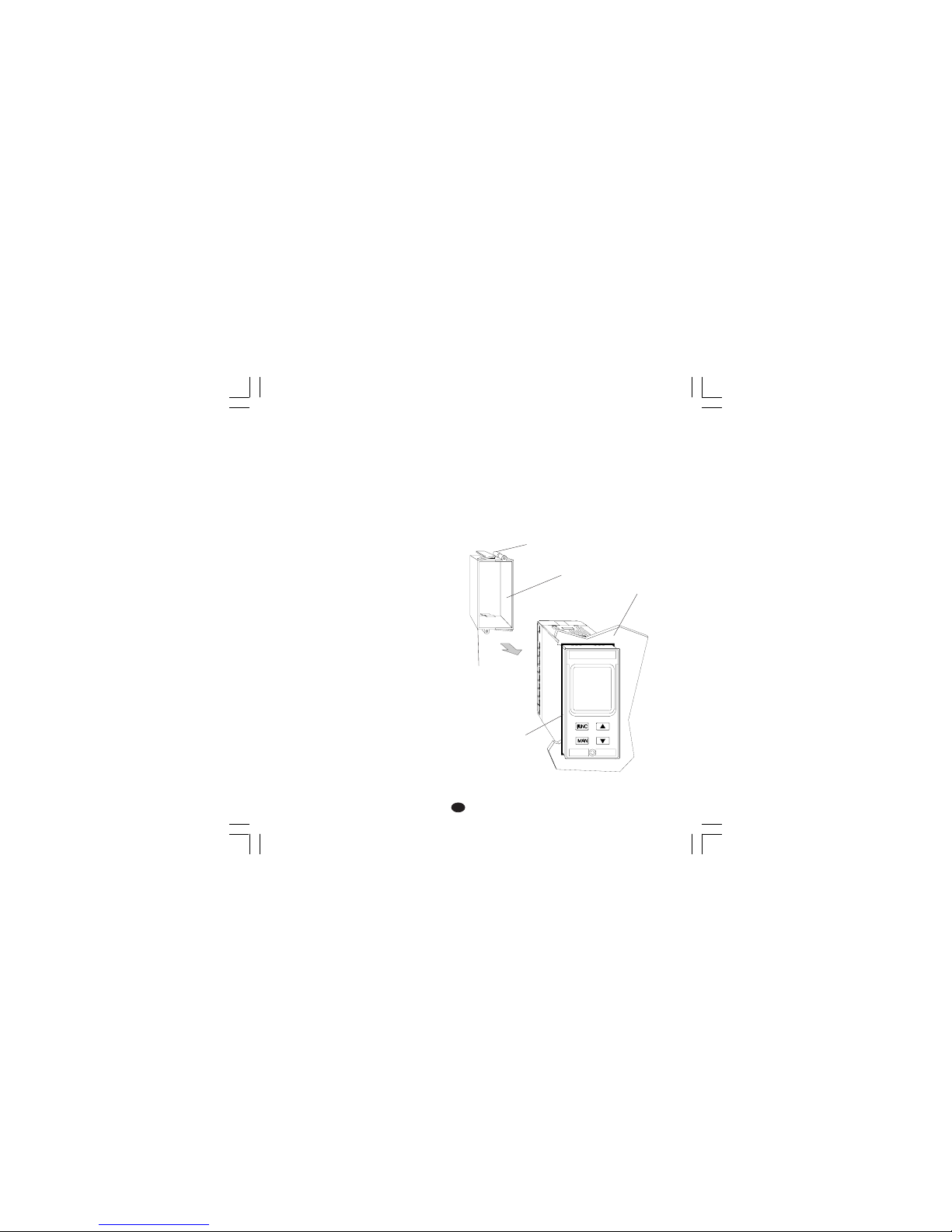
Pour le montage choisir un endroit ayant les
caractéristiques suivantes:
1) accès facile même à l'arrière
2) sans vibrations ou chocs
3) absence de gaz corrosifs (gaz sulfurés,
amoniàque, etc.)
4) absence d'eau ou d'autres liquides
5) température ambiante comprise entre 0 et
50°C
6) humidité relative de l'air comprise entre 20 et
85% HR et absence de condensation.
L'instrument peut être monté sur un panneau
d'épaisseur maxi. 15 mm après avoir exécuté un
trou rectangulaire de 45 x 92 mm.
Pour les dimensions d'encombrement et de
perçage, se reporter à la Fig. 2.
La rugosité superficielle doit être inférieure à
6,3 µmm.
L'instrument est doté d'un joint en caoutchouc
pour panneau (de 50 à 60 Sh).
Pour garantir les protections IP65 et NEMA 4X,
introduire le joint livrée avec l'appareil entre
l'instrument et le panneau (voir Figure 1).
Pour fixer l'instrument au panneau, agir comme
suit:
1) enfiler le joint sur le boîtier de l'instrument.
2) Introduire l'instrument dans le trou.
3) En maintenant fermement l'instrument sur le
panneau, introduire la bretelle de fixation.
4) Au moyen d'un tourne-vis, serrer les vis à un
couple compris entre 0,3 et 0,4 Nm.
panneau
bretelle
vis
vis
joint
Fig. 1
Nuovo-1 16/02/2005, 14.141
Page 29
2
FF
FF
F
DIMENSIONS ET PERCAGEDIMENSIONS ET PERCAGE
DIMENSIONS ET PERCAGEDIMENSIONS ET PERCAGE
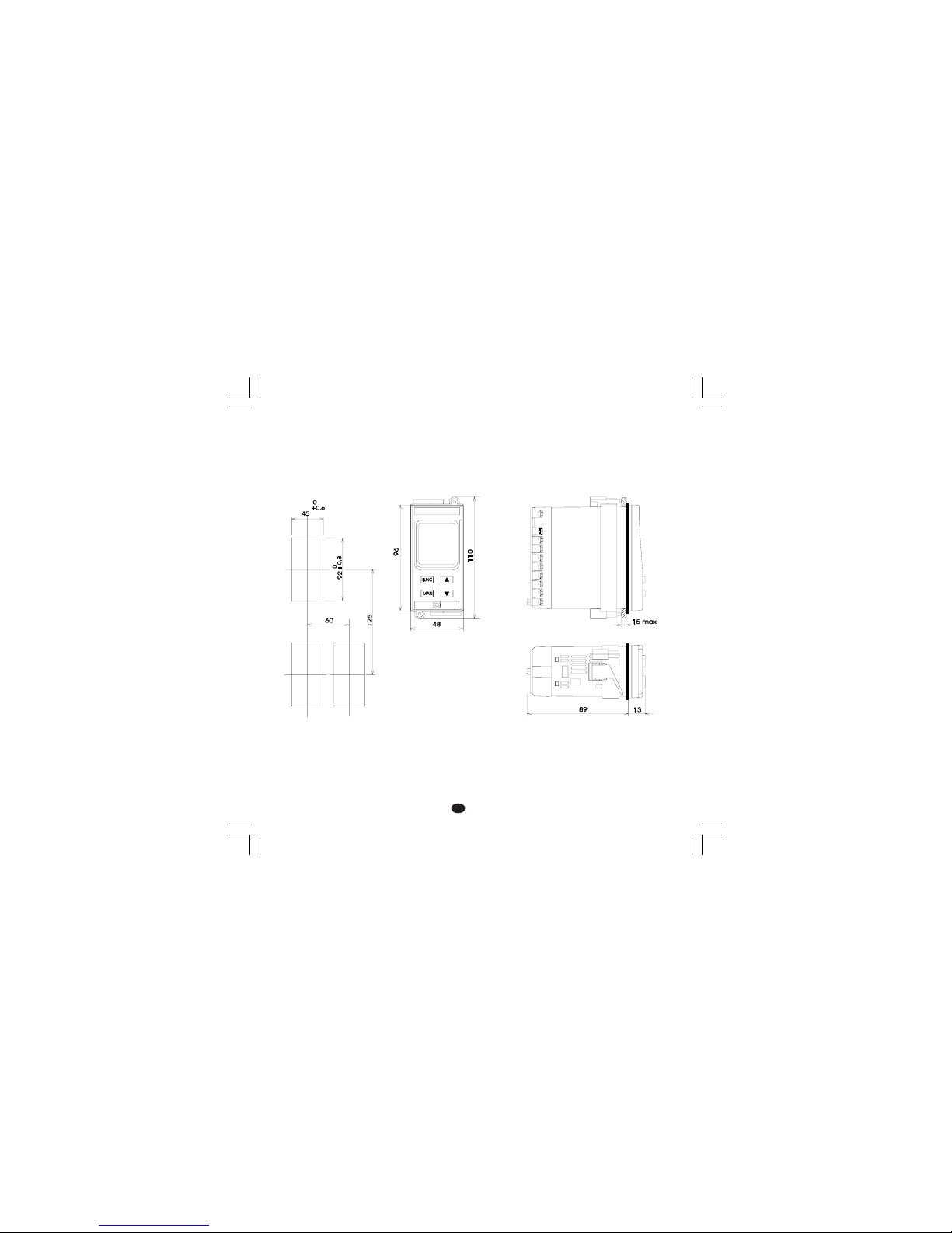
DIMENSIONS ET PERCAGE
Fig. 2
Nuovo-1 16/02/2005, 14.142
Page 30
3
FF
FF
F
RACCORDEMENTS ELECTRIQUESRACCORDEMENTS ELECTRIQUES
RACCORDEMENTS ELECTRIQUESRACCORDEMENTS ELECTRIQUES
RACCORDEMENTS ELECTRIQUES
Les raccordements électriques ne doivent être
effectués que si le boîtier de l'instrument est
régulièrement monté sur le panneau.
Fig. 3.A FACE ARRIERE (pour les instruments
avec alimentation de 100/240 Vca)
Fig. 3.B FACE ARRIERE (pour les instrumentes
avec alimentation de 24 V AC/DC)
A) ENTREES DE MESUREA) ENTREES DE MESURE
A) ENTREES DE MESUREA) ENTREES DE MESURE
A) ENTREES DE MESURE
NOTENOTE
NOTENOTE
NOTE: Des éléments extérieurs (ex. barrières
zener) raccordés entre le capteur et les bornes
d'entrée de l'instrument, peuvent provoquer des
erreurs de mesure dues à une impédence trop
élevée ou déséquilibrée, ou à la présence de
courants de perte.
ENTREE POUR THERMOCOUPLEENTREE POUR THERMOCOUPLE
ENTREE POUR THERMOCOUPLEENTREE POUR THERMOCOUPLE
ENTREE POUR THERMOCOUPLE
FIG. 4 RACCORDEMENT DE
THERMOCOUPLES
NOTESNOTES
NOTESNOTES
NOTES:
1) Ne pas placer de câbles de signaux parallèlement
ou à proximité des câbles de puissance ou des
sources de perturbations.
2) Pour le raccordement de la TC utiliser un câble
de compensation/extension approprié et,
autant que possible, blindé.
3) Quand on utilise un câble blindé, une seule
extrémité du blindage doit être raccordée à la
terre.
1
3
+
_
1
3
+
_
Blindage
Blindage
Nuovo-1 16/02/2005, 14.143
Page 31
4
FF
FF
F
ENTREE POUR THERMORESISTANCEENTREE POUR THERMORESISTANCE
ENTREE POUR THERMORESISTANCEENTREE POUR THERMORESISTANCE
ENTREE POUR THERMORESISTANCE
FIG. 5 RACCORDEMENT DE
THERMORESISTANCES
NOTENOTE
NOTENOTE
NOTE:
1) Ne pas placer les câbles des signaux
parallèlement ou à proximité des câbles de
puissance ou à des sources de perturbations.
2) Faire attention aux résistances de ligne, une
résistance de ligne trop haute (supérieure à
20 W/fil) peut provoquer des erreurs de
mesure.
3) Quand on utilise un câble blindé, une seule
extrémité du blindage doit être raccordée à la
terre.
4) Les 3 fils doivent avoir la même impédance.
B) ENTREE A PARTIR DE TRANSFORMATEURB) ENTREE A PARTIR DE TRANSFORMATEUR
B) ENTREE A PARTIR DE TRANSFORMATEURB) ENTREE A PARTIR DE TRANSFORMATEUR
B) ENTREE A PARTIR DE TRANSFORMATEUR
AMPEREMETRIQUEAMPEREMETRIQUE
AMPEREMETRIQUEAMPEREMETRIQUE
AMPEREMETRIQUE
FIG. 6 RACCORDEMENT DU
TRANSFORMATEUR
AMPEREMETRIQUE
NOTE:NOTE:
NOTE:NOTE:
NOTE:
1) L'impédance d'entrée est égale à 10 Ω.
2) Le courant maxi. d'entrée est égal à 50 mA
(50 / 60 Hz).
4
RTD
1
3 4
RTD
1
3
6
7
Transformateur
ampèremétrique
Charge
Nuovo-1 16/02/2005, 14.144
Page 32
5
FF
FF
F
2) Les raccordements de puissance doivent être
effectués à l'aide de câbles n° 16 AWG ou
supérieurs, résistant à une température mini.
de 75°C.
3) Utiliser exclusivement des conducteurs en cuivre.
4) Eviter de placer les câbles de puissance
parallèlement ou à proximité des câbles de
signaux.
5) La sortie à relais et la sortie SSR sont
disponibles. Quand la sortie à relais est utilisée
il faut invalider la sortie SSR (voir chapitre
"Mise au point préliminaire du matériel
informatique"
Les recomandations qui suivent peuvent éviter de
sérieux problèmes provoqués par l'utilisation de la
sortie 3 ou du contact NC de la sortie 1 pour
piloter des charges inductives.
CHARGES INDUCTIVESCHARGES INDUCTIVES
CHARGES INDUCTIVESCHARGES INDUCTIVES
CHARGES INDUCTIVES
Dans la commutation des charges inductives, certaines
charges inductives peuvent provoquer des transitoires
et des perturbations qui peuvent compromettre les
prestations de l'instrument.
Des problèmes analogues peuvent être créés par la
commutation des charges via un contact extérieur
monté en série sur le contact de sortie de
l'instrument.
FIG. 8 CONTACT EXTERIEUR MONTE EN
SERIE SUR LE CONTACT DE SORTIE DE
L'INSTRUMENT
C) SORTIES A RELAISC) SORTIES A RELAIS
C) SORTIES A RELAISC) SORTIES A RELAIS
C) SORTIES A RELAIS
FIG. 7 RACCORDEMENT DES SORTIES A
RELAIS
La sortie 2 et le contact NO de la sortie 1 sont
protégés au moyen de varistances, pour des
charges dont la composante inductive maxi. est
0,5A
La capacité du contact correspondant à la sortie 1
est égale à 3A/250V c.a sur charge résistive.
La capacité du contact correspondant aux sorties
2 et 3 est égale à 2A/250V c.a sur charge
résistive.
Le nombre d'opérations est égal à 1 x 10
5
fois
la capacité indiquée.
NOTENOTE
NOTENOTE
NOTE:
1) Pour éviter le risque d'électrocution ne
raccorder l'alimentation qu'après avoir effectué
tous les autres raccordements.
21
OUT 1
20
C
NO
22
NC
10
11
AL2/HBD
(OUT 3)
C - OUT 3
NO - OUT 3
16
17
AL1/COOL
(OUT 2)
C - OUT 2
NO/NC
[voir Fig. 11(J303)]
OUT 2
Ligne deLigne de
Ligne deLigne de
Ligne de
puissancepuissance
puissancepuissance
puissance
ChargeCharge
ChargeCharge
Charge
Nuovo-1 16/02/2005, 14.145
Page 33
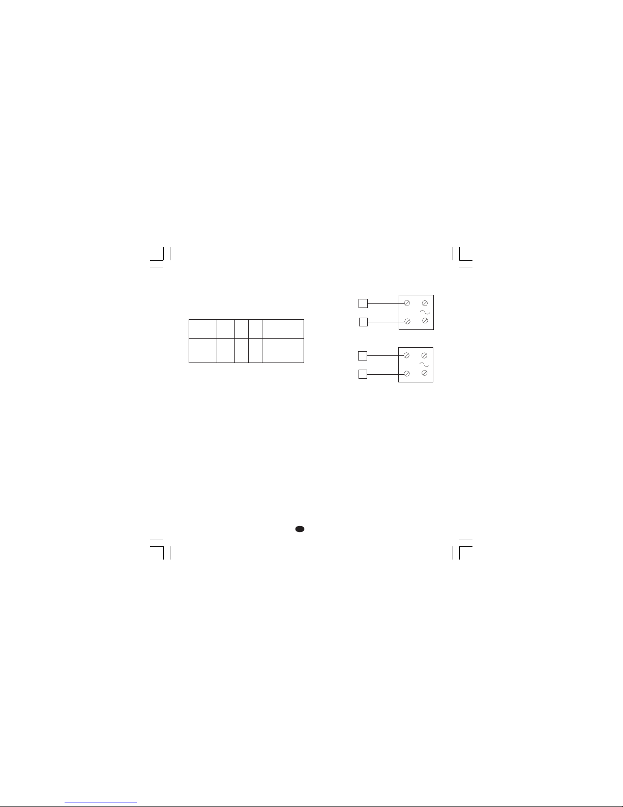
6
FF
FF
F
D) SORTIE LOGIQUE POUR LA COMMANDED) SORTIE LOGIQUE POUR LA COMMANDE
D) SORTIE LOGIQUE POUR LA COMMANDED) SORTIE LOGIQUE POUR LA COMMANDE
D) SORTIE LOGIQUE POUR LA COMMANDE
DE SSRDE SSR
DE SSRDE SSR
DE SSR
FIG. 9 RACCORDEMENT POUR LE
PILOTAGE DE RELAIS STATIQUES
Il s'agit d'une sortie à temps proportionnel.
Niveau logique 0Niveau logique 0
Niveau logique 0Niveau logique 0
Niveau logique 0: Vout < 0.5 V c.c.
Niveau logique 1Niveau logique 1
Niveau logique 1Niveau logique 1
Niveau logique 1: Courant maxi. = 20 mA.
- 14 V
+ 20 % @ 20 mA
- 24 V
+ 20 % @ 1 mA.
NOTESNOTES
NOTESNOTES
NOTES:Ces sorties NE SONT PAS isolées
1) Un isolement double ou renforcè entre
l'instrument et la ligne de puissance
doit être effectué par le relais statique
extérieur.
2) La sortie à relais et la sortie SSR
sont toutes deux disponibles. Quand
la sortie SSR est utilisée il faut
invalider la sortie relais (voir chapitre
"Mise au point préliminaire du matériel
informatique").
En de tels cas, nous recommandons de raccorder
un filtre RC en parallèle avec le contact extérieur
(ou avec le contact intérieur non protégé) suivant
les indications fig. 8.
Les valeurs de la capacité (C) et de la résistance
(R) sont indiquées au tableau suivant.
De toute façon, les câbles raccordés aux sorties à
relais, doivent être aussi éloignés que possible
des câbles des signaux.
CHARGE
(mA)
<40 mA
<150 mA
<0.5 A
C
(µF)
0.047
0.1
0.33
R
(Ω)
100
22
47
P.
(W)
1/2
2
2
TENSION DE
SERVICE
260 V AC
260 V AC
260 V AC
Relais statique
Relais statique
_
+
_
+
_
_
+
+
18
19
14
15
OUT 1
OUT 2
(AL1/Cool.)
Nuovo-1 16/02/2005, 14.146
Page 34

7
FF
FF
F
R (S,T)
13
R (S,T)
N
12
N
Réseau
de 100 V à 240 V ca (50/60Hz)
ou 24 V AC/DC
E) ALIMENTATIONE) ALIMENTATION
E) ALIMENTATIONE) ALIMENTATION
E) ALIMENTATION
Fig. 10 RACCORDEMENT A L'ALIMENTATION
NOTENOTE
NOTENOTE
NOTE:
1) Avant de raccorder l'instrument au réseau,
vérifier que la tension de ligne correspond aux
indications de la plaque signalétique de
l'instrument.
2) Pour éviter le risque d'électrocution ne raccorder
l'alimentation qu'après avoir effectué tous les
autres raccordements.
3) Le raccordement au réseau doit être effectué à
l'aide de câbles n° 16 AWG ou supérieurs,
résistant à une température mini. de 75°C.
4) Utiliser exclusivement des conducteurs en cuivre.
5) Eviter de placer les câbles des signaux
parallèlement ou à proximité des câbles de
puissance ou des sources de perturbations.
6) En cas d'alimentation 24 V c.c. la polarité n'a
aucune importance.
7) Les circuits d'alimentation NE sont PAS protégés
par un fusible, nous conseillons d'en prévoir
un à l'extérieur type T, 1 A, 250 V.
Si le fusible est endommagé nous recommandons
de vérifier tout le circuit d'alimentation. Nous
conseillons donc de renvoyer l'instrument au
fabricant.
8) Les normes sur la sécurité concernant les
instruments raccordés en permanence à
l'alimentation électrique exigent:
- d'inclure un interrupteur ou un disjoncteur
sur l'installation électrique de l'immeuble;
- il doit se trouver à proximité de l'instrument et
l'opérateur doit pouvoir y accéder facilement;
- il doit être marqué comme le dispositif de coupure
de l'instrument.
NOTENOTE
NOTENOTE
NOTE: un seul interrupteur ou disjoncteur peut
commander plusieurs instruments.
9) Si l'alimentation prevoit le fil de neutre, le brancher
au contact 12.
Nuovo-1 16/02/2005, 14.147
Page 35
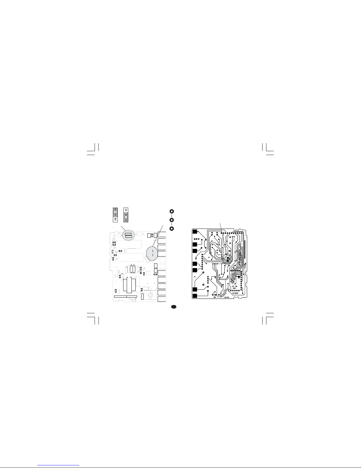
8
FF
FF
F
OUVERTURE DES RACCORDEMENTSOUVERTURE DES RACCORDEMENTS
OUVERTURE DES RACCORDEMENTSOUVERTURE DES RACCORDEMENTS
OUVERTURE DES RACCORDEMENTS
EN ENTREEEN ENTREE
EN ENTREEEN ENTREE
EN ENTREE
Cet instrument permet de relever l'ouverture du
circuit d'entrée pour les entrées de TC ou RTD.
L'ouverture de l'entrée RTD est indiquée comme
une condition de dépassement d'échelle positif.
Pour l'entrée à partir de thermocouple,
sélectionner l'indication de dépassement d'échelle
positif (standard) en fermant CH2 et en ouvrant
SH2 ou l'indication de dépassement d'échelle
négatif en ouvrant CH2 et en fermant SH2.
Les deux contacts sont sur le côté soudure de la
carte CPU (voir dessin).
Fig. 12
MISE AU POINT PRELIMINAIRE DUMISE AU POINT PRELIMINAIRE DU
MISE AU POINT PRELIMINAIRE DUMISE AU POINT PRELIMINAIRE DU
MISE AU POINT PRELIMINAIRE DU
MATERIEL INFORMATIQUEMATERIEL INFORMATIQUE
MATERIEL INFORMATIQUEMATERIEL INFORMATIQUE
MATERIEL INFORMATIQUE
1) Extraire l'instrument de son boîtier.
2) Pour les sorties 1 et 2, sélectionner la sortie
désirée et programmer les pontets J 304 et J305
J304 (AL1, Cool.) 1-2 = SSR 2-3 = Relais
J305 (Sortie principale) 1-2 = SSR 2-3 = Relais
3) Pour la sortie 2 on peut sélectionner le contact
utilisé (NO ou NC) au moyen du pontet J303
J303 (AL1, Cool.) 1-2 = Out NO 2-3 = Out NC
Note: Note:
Note: Note:
Note: J303 est un pontet à souder; il est effectué du
côté de la soudure.
1
1
1
23
4
+
-
+
B
C
E
I
1
3
4
7
1
1
XY00
I
1
2
3
12
3
45
12
345
J301
J302
L305
R301
R303
D
3
0
5
C308
C306
C307
R305
C312
C310
D307
R308
C309
PZ12
PZ13
PZ14
PZ15
PZ16
PZ19
PZ20
PZ21
PZ22
R307
R306
Q302
U302
TR301
J304
J305
Y301
D306
D308
D304
U301
PZ18
PZ17
C301
C
3
0
4
J303
C303
C311
C302
C305
C314
C313
L304
L301
L303
L302
R309
R310
R312
R314
R311
R302
R304
R313
Q303
Q305
D302
Q301
Q304
D301
D310
K302
K301
J 303
1
3
J304 J305
1
FIG. 11
CH2
SH2
Nuovo-1 16/02/2005, 14.148
Page 36

9
FF
FF
F
NOTES GENERALES de configurationNOTES GENERALES de configuration
NOTES GENERALES de configurationNOTES GENERALES de configuration
NOTES GENERALES de configuration
FUNC = Permet de mémoriser la nouvelle
valeur du paramètre sélectionné et
passer au paramètre suivant (ordre
croissant).
SMRT = Permet de visualiser les paramètres
en ordre décroissant sans mémoriser
les nouvelles valeurs.
= Permet d'augmenter la valeur du
paramètre sélectionné.
= Permet de diminuer la valeur du
paramètre sélectionné.
PROCEDURES DE CONFIGURATIONPROCEDURES DE CONFIGURATION
PROCEDURES DE CONFIGURATIONPROCEDURES DE CONFIGURATION
PROCEDURES DE CONFIGURATION
1) Extraire l'instrument de son boîtier.
2) Préparer le contact interne V2 (voir fig.
suivante) sur la position ouverte.
Fig.13
3) Rebrancher l'instrument
4) Alimenter l'instrument, l'indicateur supérieur
indique "CnF"
ATTENTIONATTENTION
ATTENTIONATTENTION
ATTENTION: Si l'instrument affiche "CAL"
appuyer immédiatement sur la touche pour
revenir à la procédure de configuration.
5) Appuyer sur la touche FUNC. L'indicateur
inférieur visualise le code du paramètre
sélectionné et l'indicateur supérieur en
visualise la nouvelle valeur.
P1 - Type d'entrée et échelle standardP1 - Type d'entrée et échelle standard
P1 - Type d'entrée et échelle standardP1 - Type d'entrée et échelle standard
P1 - Type d'entrée et échelle standard
0 = TC type L échelle 0 / +800 °C
1 = TC type J échelle 0 / +800 °C
2 = TC type K échelle 0 / +999 °C
3 = TC type N échelle 0 / +999 °C
4 = RTD type Pt 100 échelle -199 / +500 °C
5 = RTD type Pt 100 échelle -19.9 / +99.9 °C
6 = TC type T échelle 0 / +400 °C
8 = TC type L échelle 0 / +999 °F
9 = TC type J échelle 0 / +999 °F
10 = TC type K échelle 0 / +999 °F
11 = TC type N échelle 0 / +999 °F
12 = RTD type Pt 100 échelle -199 / +999 °F
13 = TC type T échelle 0 / +752 °F
P2 = Echelle mini.P2 = Echelle mini.
P2 = Echelle mini.P2 = Echelle mini.
P2 = Echelle mini.
Non disponible si P1 = 5
Valeur d'échelle mini. utilisée par l'algorithme PID
pour les calculs de l'étendue de l'échelle
d'utilisation. P2 est programmable à l'intérieur de
la plage d'entrée sélectionnée au moyen de P1.
Quand P2 est modifié, l'instrument attribue
automatiquement au paramètre rL la nouvelle
valeur de P2.
V2
Nuovo-1 16/02/2005, 14.149
Page 37

10
FF
FF
F
P3 = Echelle maxi.P3 = Echelle maxi.
P3 = Echelle maxi.P3 = Echelle maxi.
P3 = Echelle maxi.
Non disponible si P1 = 5
Valeur d'échelle maxi. utilisée par l'algorithme PID
pour les calculs de l'étendue de l'échelle
d'utilisation.
P3 est programmable à l'intérieur de l'échelle
d'utilisation sélectionnée au moyen de P1.
Quand le paramètre P3 est modifié, l'instrument
attribue automatiquement au paramètre rH la
nouvelle valeur de P3.
NOTE: NOTE:
NOTE: NOTE:
NOTE: l'étendue de l'échelle d'utilisation (P3 - P2)
doit être supérieure ou égale à:
- 300 °C ou 600 °F pour entrée de TC;
- 100 °C ou 200 °F pour entrée de RTD.
P4 = Procédure de configuration des sortiesP4 = Procédure de configuration des sorties
P4 = Procédure de configuration des sortiesP4 = Procédure de configuration des sorties
P4 = Procédure de configuration des sorties
H = Chauffage
HC = Chauffage/Refroidissement.
P5 = Type sortie principaleP5 = Type sortie principale
P5 = Type sortie principaleP5 = Type sortie principale
P5 = Type sortie principale
rEL = Sortie à relais.
SSr = Sortie pour SSR.
NOTE:NOTE:
NOTE:NOTE:
NOTE:
Programmer P5 = rEL,le paramètre C est forcé
sur la valeur 20 secondes.
Programmer P5=SSr, le paramètre C est forcé
sur la valeur 2 secondes.
P6 = Type sortie refroidissementP6 = Type sortie refroidissement
P6 = Type sortie refroidissementP6 = Type sortie refroidissement
P6 = Type sortie refroidissement
Uniquement disponible si P4 = HC
AIr = air
OIL = huile
H2O = eau
NO TENO TE
NO TENO TE
NO TE:
Programmer P6 = Air, le paramètre C2 est forcé
sur la valeur 10 sec. et le
paramètre rC prend la
valeur 1,00.
Programmer P6=OiL, Le paramètre C2 est forcé
sur la valeur 4 sec. et le
paramètre rC prend la
valeur 0,8.
Programmer P6=H2O,Le paramètre C2 est forcé
sur la valeur 2 sec. et le
paramètre rC prend la
valeur 0,4.
P7 = Alarme 1P7 = Alarme 1
P7 = Alarme 1P7 = Alarme 1
P7 = Alarme 1
Uniquement disponible si P4 = H.
0 = Non prévu
1 = Alarme de procédé
2 = Alarme de bande
3 = Alarme de déviation
P8 = Dialogue utilisateur alarme 1P8 = Dialogue utilisateur alarme 1
P8 = Dialogue utilisateur alarme 1P8 = Dialogue utilisateur alarme 1
P8 = Dialogue utilisateur alarme 1
Uniquement disponible si P7 est différent de 0 et
P4 = H
H.A. = Alarme de maximum (hors bande) avec
acquit automatique.
L.A. = Alarme de minimum (à l'intérieur de la ban-
de) avec acquit automatique.
H.L. = Alarme de maximum (hors bande) avec
acquit manuel.
L.L. = Alarme de minimum (à l'intérieur de la ban-
de) avec acquit manuel.
P9 = Masquage de l'alarme 1P9 = Masquage de l'alarme 1
P9 = Masquage de l'alarme 1P9 = Masquage de l'alarme 1
P9 = Masquage de l'alarme 1
Uniquement disponible si P7 est différent de 0 et
P4 = H
OFF =masquage invalidé
ON = masquage autorisé
NOTENOTE
NOTENOTE
NOTE: le masquage permet d'invalider l'action
des alarmes au départ ou, uniquement pour les
alarmes de bande et de déviation, après les
modifications du point de consigne. Les alarmes
sont réamorcer automatiquement quand la
condition d'alarme n'existe plus.
Nuovo-1 16/02/2005, 14.1410
Page 38
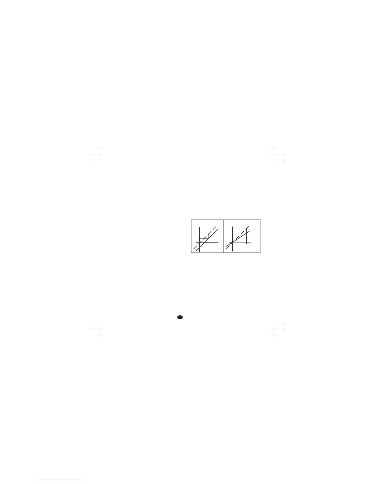
11
FF
FF
F
P10 = Alarme 2P10 = Alarme 2
P10 = Alarme 2P10 = Alarme 2
P10 = Alarme 2
0 = Non prévu
1 =Alarme de procédé
2 = Alarme de bande
3 = Alarme de déviation
La sortie de l'alarme 2 est en OR avec la sortie de
la fonction HBD (voir paramètre P16).
P11 = Dialogue utilisateur alarme 2 et acquitP11 = Dialogue utilisateur alarme 2 et acquit
P11 = Dialogue utilisateur alarme 2 et acquitP11 = Dialogue utilisateur alarme 2 et acquit
P11 = Dialogue utilisateur alarme 2 et acquit
de l'alarme HBDde l'alarme HBD
de l'alarme HBDde l'alarme HBD
de l'alarme HBD
Uniquement disponible si P10 est différent de 0
ou P16 est différent de OFF.
H.A.= Alarme de maximum (hors bande) avec
acquit automatique.
L.A.= Alarme de minimum (à l'intérieur de la ban-
de) avec acquit automatique.
H.L.= Alarme de maximum (hors bande) avec
acquit manuel.
L.L. = Alarme de minimum (à l'intérieur de la ban-
de) avec acquit manuel.
NOTENOTE
NOTENOTE
NOTE: l'alarme HBD est toujours une alarme de
minimum mais prend le type d'acquit
sélectionné pour l'alarme 2.
P12 = Masquage de l'alarme 2P12 = Masquage de l'alarme 2
P12 = Masquage de l'alarme 2P12 = Masquage de l'alarme 2
P12 = Masquage de l'alarme 2
Uniquement disponible si P10 est différent de 0.
OFF = masquage invalidé
ON = masquage autorisé
Pour plus de détails voir le paramètre P9.
P13 = Type de DEVIATION sur la mesureP13 = Type de DEVIATION sur la mesure
P13 = Type de DEVIATION sur la mesureP13 = Type de DEVIATION sur la mesure
P13 = Type de DEVIATION sur la mesure
P13 = 0 DEVIATION (P14) constante
sur toute l'échelle.
P13 diffèrent de 0 P13 indique le point
d'application de la valeur de
déviation programmée avec
le paramètre P14.
NOTENOTE
NOTENOTE
NOTE: les paramètres P13 et P14 NE modifient
PAS les limites de mesure ou de visualisation de
l'instrument; si l'une de ces limites est franchie elle
déclenche une signalisation de hors échelle.
P14 = Valeur de DEVIATIONP14 = Valeur de DEVIATION
P14 = Valeur de DEVIATIONP14 = Valeur de DEVIATION
P14 = Valeur de DEVIATION
Si P13 = 0, P 14 est programmable, en unités
techniques, de -20% à +20% de
l'échelle d'entrée (P1).
Se P13 est différent de 0, P 14 est programmable,
en unités techniques, de -20% à +20%
de la valeur de P13.
NOTENOTE
NOTENOTE
NOTE: le paramètre P14 ne peut pas avoir une
valeur inférieure à -199 unités.
P15P15
P15P15
P15
==
==
=
Seuil de la fonction “Soft Start”Seuil de la fonction “Soft Start”
Seuil de la fonction “Soft Start”Seuil de la fonction “Soft Start”
Seuil de la fonction “Soft Start”
(départ doux).(départ doux).
(départ doux).(départ doux).
(départ doux).
Valeur de seuil, en unités techniques, utilisée par
l'instrument pour l'insertion automatique de la
fonction "Soft Start" (limite temporisée de la
puissance de sortie).
Au moment de la mise en service de l'instrument, si
la valeur mesurée est inférieure au seuil programmé,
l'instrument introduit automatiquement la limite de la
puissance de sortie et la maintient pendant un laps
de temps programmé (voir le paramètre "tOL" par.
"PARAMETRES DE FONCTIONNEMENT").
Au moment de la mise en service, si le paramètre
"tOL" est égal à l'infini (limite toujours insérée),
l'instrument ignore ce paramètre.
P13 = 0
Visual.
Courbe
correcte
Entrée
P14
Courbe
réelle
P13
Visual.
P14
Entrée
Courbe
réelle
Courbe
correcte
Nuovo-1 16/02/2005, 14.1411
Page 39

12
FF
FF
F
P16 =P16 =
P16 =P16 =
P16 =
Mesure du courant utilisé par la chargeMesure du courant utilisé par la charge
Mesure du courant utilisé par la chargeMesure du courant utilisé par la charge
Mesure du courant utilisé par la charge
commandée par la sortie principalecommandée par la sortie principale
commandée par la sortie principalecommandée par la sortie principale
commandée par la sortie principale
(HBD)(HBD)
(HBD)(HBD)
(HBD)
OFF = Mesure non autorisée
n.O. = Mesure autorisée sur la période ON (état
1 pour SSR ou charge pilotée par le
contact NO)
n.C. = Mesure autorisée sur la période OFF
(état 0 pour SSR ou charge pilotée par le
contact NC)
P17 =P17 =
P17 =P17 =
P17 =
Echelle maxi. transformateurEchelle maxi. transformateur
Echelle maxi. transformateurEchelle maxi. transformateur
Echelle maxi. transformateur
ampèremétriqueampèremétrique
ampèremétriqueampèremétrique
ampèremétrique
Uniquement disponible si P16 est différent de
OFF.
10 = 10 A échelle maxi. (résolution 0.1 A)
25 = 25 A échelle maxi. (résolution 1 A)
50 = 50 A échelle maxi. (résolution 1 A)
100 = 100 A échelle maxi. (résolution 1 A)
P18 = Clé d'accès aux paramètres de contrôleP18 = Clé d'accès aux paramètres de contrôle
P18 = Clé d'accès aux paramètres de contrôleP18 = Clé d'accès aux paramètres de contrôle
P18 = Clé d'accès aux paramètres de contrôle
0 = paramètres toujours accessibles
1 = SP peut être modifiés tandis que tous les autres
paramètres sont toujours protégés
de 2 à 499 = SP peut toujours être modifié tandis
que ce code numérique permet
l'accès ou l'invalidation de la
modification des autres paramètres
de fonctionnement.
de 500 à 999 = SP, A1 et A2 peuvent toujours
être modifiés tandis que ce code
numérique permet l'accès ou
l'invalidation de la modification
des autres paramètres de
fonctionnement.
NOTENOTE
NOTENOTE
NOTE: après avoir appuyé sur la touche FUNC,
on NE peut PLUS visualiser la valeur de ce
paramètre. Si l'ancien code de sécurité est
inconnu il faut en programmer un autre.
La procédure de configuration standard est
complète et l'instrument visualise "
-.-.-." sur
les deux indicateurs.
Sans autres programmations, appuyer sur FUNC
et l'instrument retourne au début de la procédure
de configuration.
Pour effectuer une configuration complète,
appuyer sur les touches ou et programmer
la valeur 217 sur l'indicateur supérieur.
Appuyer sur la touche FUNC et l'instrument
commence la procédure de configuration
auxiliaire en visualisant les paramètres
supplémentaires suivants:
P19 - Action de la sortie principaleP19 - Action de la sortie principale
P19 - Action de la sortie principaleP19 - Action de la sortie principale
P19 - Action de la sortie principale
Uniquement disponible si P4 = H.
r = Inverse (chauffage)
d = Directe (refroidissement)
Note : quand P4 = HC, ce paramètre est forcé à "r".
P21 - Action du relais de l'alarme 1P21 - Action du relais de l'alarme 1
P21 - Action du relais de l'alarme 1P21 - Action du relais de l'alarme 1
P21 - Action du relais de l'alarme 1
Ce paramètre est visualisé uniquement si P7 est
différent de 0 et P4 est égal à H.
r = inverse (relais désexcité en condition
d'alarme).
d = directe (relais excité en condition d'alarme)
t
Entrée
t
Sortie
t
Entrée
t
Sortie
Inverse Directe
Nuovo-1 16/02/2005, 14.1412
Page 40

13
FF
FF
F
P22 - Action du relais de l'alarme 2P22 - Action du relais de l'alarme 2
P22 - Action du relais de l'alarme 2P22 - Action du relais de l'alarme 2
P22 - Action du relais de l'alarme 2
Ce paramètre N'EST PAS visualisé si P10 est
égal à 0 et P16 est égal à "OFF".
r = inverse (relais désexcité en condition
d'alarme).
d = directe (relais excité en condition d'alarme)
P23 - Modification automatique du "gainP23 - Modification automatique du "gain
P23 - Modification automatique du "gainP23 - Modification automatique du "gain
P23 - Modification automatique du "gain
concernant le refroidissement".concernant le refroidissement".
concernant le refroidissement".concernant le refroidissement".
concernant le refroidissement".
Uniquement disponible si P4=HC.
OFF = La fonction SMART
NENE
NENE
NE modifie
PAS PAS
PAS PAS
PAS la
valeur du paramètre "gain relatif de
refroidissement".
ON = La fonction SMART modifie la valeur du
paramètre "gain relatif de refroidissement".
P24 - Vitesse maxi. de variation du signal deP24 - Vitesse maxi. de variation du signal de
P24 - Vitesse maxi. de variation du signal deP24 - Vitesse maxi. de variation du signal de
P24 - Vitesse maxi. de variation du signal de
sortiesortie
sortiesortie
sortie
Ce paramètre permet de programmer la vitesse
maxi. du signal de sortie.
P24 est programmable de 1 à 10% de l'échelle de
sortie par seconde.
Au-delà de 10% l'indicateur supérieur s'éteint et
l'instrument ne limite plus la vitesse de variation.
P25 - Visualisation des paramètres protégésP25 - Visualisation des paramètres protégés
P25 - Visualisation des paramètres protégésP25 - Visualisation des paramètres protégés
P25 - Visualisation des paramètres protégés
Ce paramètre n'est visualisé que si P18 est
différent de 0.
OFF = L'instrument NE visualise PAS les
paramètres protégés.
ON = Tous les paramètres peuvent être
visualisés.
P26 - SMART autorisation/invalidationP26 - SMART autorisation/invalidation
P26 - SMART autorisation/invalidationP26 - SMART autorisation/invalidation
P26 - SMART autorisation/invalidation
0 = La fonction SMART est toujours invalidée
1 = L'autorisation et l'invalidation de la fonction
SMART
NE NE
NE NE
NE sont
PAS PAS
PAS PAS
PAS protégées par la clé de
sécurité.
2 = L'autorisation et l'invalidation de la fonction
SMART sont protégées par la clé de
sécurité.
P27 - Valeur de bande proportionnelle maxi.P27 - Valeur de bande proportionnelle maxi.
P27 - Valeur de bande proportionnelle maxi.P27 - Valeur de bande proportionnelle maxi.
P27 - Valeur de bande proportionnelle maxi.
programmable par la fonction SMART.programmable par la fonction SMART.
programmable par la fonction SMART.programmable par la fonction SMART.
programmable par la fonction SMART.
Uniquement disponible si P26 est différent de 0.
Ce paramètre peut être programmé entre la
valeur de P28 ou P29 et 99.9.
P28 - Valeur de bande proportionnelle mini.P28 - Valeur de bande proportionnelle mini.
P28 - Valeur de bande proportionnelle mini.P28 - Valeur de bande proportionnelle mini.
P28 - Valeur de bande proportionnelle mini.
programmable par la fonction SMART.programmable par la fonction SMART.
programmable par la fonction SMART.programmable par la fonction SMART.
programmable par la fonction SMART.
Uniquement disponible si P4=H et P26 est
différent de 0.
Ce paramètre peut être programmé entre 1,0%
et la valeur de P27.
P29 - Valeur de bande proportionnelle mini.P29 - Valeur de bande proportionnelle mini.
P29 - Valeur de bande proportionnelle mini.P29 - Valeur de bande proportionnelle mini.
P29 - Valeur de bande proportionnelle mini.
programmable par la fonction SMARTprogrammable par la fonction SMART
programmable par la fonction SMARTprogrammable par la fonction SMART
programmable par la fonction SMART
uniquement pour le réglage chauffage/uniquement pour le réglage chauffage/
uniquement pour le réglage chauffage/uniquement pour le réglage chauffage/
uniquement pour le réglage chauffage/
refroidissement.refroidissement.
refroidissement.refroidissement.
refroidissement.
Uniquement disponible si P4=HC et P26 est
différent de 0.
Ce paramètre peut être programmé entre 1,5% et
la valeur de P27.
Nuovo-1 16/02/2005, 14.1413
Page 41

14
FF
FF
F
P30 - Valeur mini. de temps intégralP30 - Valeur mini. de temps intégral
P30 - Valeur mini. de temps intégralP30 - Valeur mini. de temps intégral
P30 - Valeur mini. de temps intégral
programmable par la fonction SMART.programmable par la fonction SMART.
programmable par la fonction SMART.programmable par la fonction SMART.
programmable par la fonction SMART.
Uniquement disponible si P26 est différent de 0.
Ce paramètre peut être programmé entre 00,1
(mm.s) et 02,0 (mm.s).
P31 = Extension de l'anti-initialisation-wind upP31 = Extension de l'anti-initialisation-wind up
P31 = Extension de l'anti-initialisation-wind upP31 = Extension de l'anti-initialisation-wind up
P31 = Extension de l'anti-initialisation-wind up
Echelle: de -30 à +30 % de la bande
proportionnelle.
NOTENOTE
NOTENOTE
NOTE: une valeur positive augmente la limite
maxi. de la fonction (au-dessus du point de
consigne) tandis qu'une valeur négative diminue
la limite mini. de la fonction (en-dessous du point
de consigne)
La configuration auxiliaire est complète et
l'instrument visualise "CnF" sur l'indicateur
supérieur.
DIALOGUE UTILISATEURDIALOGUE UTILISATEUR
DIALOGUE UTILISATEURDIALOGUE UTILISATEUR
DIALOGUE UTILISATEUR
1) Extraire l'instrument de son boîtier.
2) Placer le contact V2 (voir fig. 13) sur la position
fermée.
3) Rebrancher l'instrument.
4) Alimenter l'instrument.
L'indicateur supérieur visualise la valeur mesurée
tandis que l'indicateur inférieur indique la valeur
de point de consigne programmée (cet état est
défini "mode normal de visualisation").
NoteNote
NoteNote
Note: Quand on applique une rampe (paramètre
rP) au point de consigne de fonctionnement,
la valeur du point de consigne mesurée
pourrait être différente de celle de
fonctionnement.
Appuyer sur la touche , si la fonction HBD est
configurée, la sortie de contrôle est autorisée et
l'instrument est en état normal de visualisation, on
peut visualiser sur l'indicateur inférieur la valeur de
courant utilisée par la charge pilotée au moyen de
la sortie 1 suivie par le symbole A.
NOTENOTE
NOTENOTE
NOTE: cette visualisation N'est PAS soumise au
temps différé. Pour retourner à l'état normal de
visualisation, appuyer de nouveau sur la touche .
Nuovo-1 16/02/2005, 14.1414
Page 42

15
FF
FF
F
INVALIDATION DU SIGNAL DE SORTIEINVALIDATION DU SIGNAL DE SORTIE
INVALIDATION DU SIGNAL DE SORTIEINVALIDATION DU SIGNAL DE SORTIE
INVALIDATION DU SIGNAL DE SORTIE
Le TMS permet d'invalider manuellement le
signal de sortie pour interrompre la régulation
(l'instrument fonctionne comme un simple
indicateur).
Pour invalider le signal de sortie agir comme suit:
1) Appuyer sur la touche et la maintenir
enfoncée.
2) Appuyer sur la touche FUNC.
3) Appuyer sur les deux touches pendant plus de
3 secondes.
L'indicateur inférieur visualise le message "OFF"
et la sortie de régulation est interdite.
Pour réactiver la régulation automatique, répéter
les actions susmentionnées; l'instrument retourne
automatiquement à l'état "Visualisation Normale".
NOTES:NOTES:
NOTES:NOTES:
NOTES: 1) L'instrument mémorise l'état
d'invalidation de la sortie.
2) Si le signal de sortie est invalidé
quand la fonction SMART effectue la
première partie de l'algorithme
d'auto-syntonisation (LED SMRT
clignotante), l'instrument n'exécute
pas l'algorithme et, quand on
retourne au contrôle normal, la
fonction SMART est invalidée. Si le
signal de sortie est invalidé quand la
fonction SMART effectue la partie
de syntonisation continue de
l'algorithme d'auto-syntonisation
(LED SMRT allumée fixe),
l'instrument arrête provisoirement
l'exécution de l'algorithme et, au
retour à l'état normal de contrôle, la
fonction SMART est active.
ALGORITHME SMARTALGORITHME SMART
ALGORITHME SMARTALGORITHME SMART
ALGORITHME SMART
L'algorithme SMART est un nouvel algorithme d'auto-syntonisation automatique. SMART est utilisé
par l'instrument pour calculer et programmer
automatiquement les paramètres de régulation.
L'algorithme SMART peut être toujours inséré
pour obtenir une optimisation continue des
paramètres en fonction des changements
éventuels des conditions de l'installation.
Pour autoriser cette fonction, appuyer sur la
touche SMRT pendant plus de 1,5 sec.quand
l'instrument est en état "Visualisation normale".
L'indicateur SMRT clignote ou s'allume en
fonction du type de syntonisation en cours.
Pour invalider la fonction SMART, il suffit
d'appuyer sur la touche SMRT; l'indicateur SMRT
s'éteint.
NOTESNOTES
NOTESNOTES
NOTES:
1) Quand la fonction SMART est active, le gain
concernant le refroidissement (s'il existe) est
limité à l'intérieur des valeurs suivantes:
Elément refroidissant Echelle
Air de 0,85 à 1,00
Huile de 0,80 à 0,90
Ea u de 0,30 à 0,60
2) La fonction SMART utilise une action de
dérivation égale à 1/4 de l'action intégrale.
3) Les limites de la bande proportionnelle et du
temps intégral programmables par la fonction
SMART sont programmable au moyen des
paramètres P27, P28, P29 et P30 (voir
section 3).
4) L'autorisation/invalidation de la fonction
SMART peut être protégée par la clé de
sécurité (voir paramètre P18).
5) Quand la fonction SMART est active, les
paramètres Pb, ti et td ne peuvent pas être
modifiés au clavier. Pour le paramètre rC voir
P23.
Nuovo-1 16/02/2005, 14.1415
Page 43

16
FF
FF
F
ALARME DE ALARME DE
ALARME DE ALARME DE
ALARME DE
DYSFONCTIONNEMENT DE LADYSFONCTIONNEMENT DE LA
DYSFONCTIONNEMENT DE LADYSFONCTIONNEMENT DE LA
DYSFONCTIONNEMENT DE LA
CHARGE COMMANDEE VIA LACHARGE COMMANDEE VIA LA
CHARGE COMMANDEE VIA LACHARGE COMMANDEE VIA LA
CHARGE COMMANDEE VIA LA
SORTIE PRINCIPALE (alarme HBD) .SORTIE PRINCIPALE (alarme HBD) .
SORTIE PRINCIPALE (alarme HBD) .SORTIE PRINCIPALE (alarme HBD) .
SORTIE PRINCIPALE (alarme HBD) .
Cette alarme permet de contrôler constamment
l'absorption de la charge pilotée au moyen de la
sortie principale et de créer une alarme si la
consommation est inférieure à la valeur de seuil
programmée.
Pour visualiser la consommation de cette charge,
appuyer sur la touche quand l'instrument est
en état de "Visualisation normale".
L'indicateur supérieur permet de visualiser la
variable de procédé tandis que l'indicateur
inférieur visualise le courant absorbé (en Ampère)
suivi par l'unité technique (A)
Pour retourner à l'état "Visualisation normale"
appuyer de nouveau sur la touche .
Si l'instrument relève une condition d'alarme, la
LED AL2/HB clignote et le relais concernant la
sortie 3 est activé.
ACCES DIRECT A LA MODIFICATION DUACCES DIRECT A LA MODIFICATION DU
ACCES DIRECT A LA MODIFICATION DUACCES DIRECT A LA MODIFICATION DU
ACCES DIRECT A LA MODIFICATION DU
POINT DE CONSIGNEPOINT DE CONSIGNE
POINT DE CONSIGNEPOINT DE CONSIGNE
POINT DE CONSIGNE
L'instrument permet de modifier la valeur du point
de consigne sans utiliser la touche FUNC.
Pour modifier rapidement la valeur du point de
consigne, agir comme suit:
1) Appuyer pendant plus de 3 secondes sur la
touche ou , et la valeur du point de
consigne visualisée par l'indicateur inférieur
commence à se modifier.
2) En appuyant sur les touches et ,
programmer la valeur de point de consigne
désirée.
3) Quand la valeur désirée est atteinte, N'appuyer
sur AUCUNE touche pendant au moins 3
secondes; la nouvelle valeur du point de
consigne devient opérationnelle 3 secondes
après la dernière pression sur les touches.
Pour abandonner la modification au cours de
cette procédure, appuyer sur la touche FUNC;
l'instrument se replace automatiquement sur
"visualisation normale" sans mémoriser la
nouvelle valeur.
LAMP TESTLAMP TEST
LAMP TESTLAMP TEST
LAMP TEST
Pour vérifier le fonctionnement de l'indicateur,
appuyer sur les touches et FUNC.
L'instrument allume toutes les LED de l'indicateur
avec un cycle de fonctionnement égal à 50% (cet
état est appelé LAMP TEST).
Le LAMP TEST n'est pas soumis au temps
différé.
Pour retourner à l'état normal de visualisation,
appuyer de nouveau sur les touches et FUNC.
Pendant le LAMP TEST l'instrument conserve
son fonctionnement normal, mais le clavier ne
permet que l'invalidation du test.
Nuovo-1 16/02/2005, 14.1416
Page 44

17
FF
FF
F
Paramètres: description
SP
Point de consigne principalPoint de consigne principal
Point de consigne principalPoint de consigne principal
Point de consigne principal (en unités
techniques)
Echelle : de rL à rH.
n.rS
Acquit manuel des alarmesAcquit manuel des alarmes
Acquit manuel des alarmesAcquit manuel des alarmes
Acquit manuel des alarmes
Ce paramètre est visualisé si une alarme au
moins est programmée avec l'acquit
manuel.
Programmer ON et appuyer sur la touche
FUNC pour réamorcer les alarmes.
nnn
Clé de protection des paramètresClé de protection des paramètres
Clé de protection des paramètresClé de protection des paramètres
Clé de protection des paramètres
Elle n'est pas visualisée si P18= 0 ou1.
L'instrument visualise d'abord l'état du
dispositif:
ON= La protection des paramètres est
active
OFF= La protection des paramètres est
inactive
Pour désactiver la protection des
paramètres, programmer une valeur égale
à la valeur attribuée au paramètre P18.
Pour activer de nouveau la protection des
paramètres, programmer une valeur
différente de celle qui est attribuée au
paramètre P18.
A1
Seuil d'alarme 1Seuil d'alarme 1
Seuil d'alarme 1Seuil d'alarme 1
Seuil d'alarme 1
Ce paramètre est visualisé uniquement si
l'alarme correspondante a été configurée
Echelles:
- à l'intérieur de l'échelle d'entrée pour
l'alarme de procédé.
- de 0 à 500 unités pour les alarmes de
bande.
- de -199 à 500 unités pour les alarmes de
déviation.
A2
Seuil d'alarme 2Seuil d'alarme 2
Seuil d'alarme 2Seuil d'alarme 2
Seuil d'alarme 2
Pour plus de détails voir le paramètre A1.
PARAMETRES DE FONCTIONNEMENTPARAMETRES DE FONCTIONNEMENT
PARAMETRES DE FONCTIONNEMENTPARAMETRES DE FONCTIONNEMENT
PARAMETRES DE FONCTIONNEMENT
Modification des paramètres deModification des paramètres de
Modification des paramètres deModification des paramètres de
Modification des paramètres de
fonctionnementfonctionnement
fonctionnementfonctionnement
fonctionnement
Appuyer sur la touche FUNC, l'indicateur
inférieur visualise le code et l'indicateur supérieur
visualise la valeur du paramètre sélectionné.
En appuyant sur les touches et on peut
programmer la valeur ou l'état désiré.
En appuyant sur la touche FUNC l'instrument
mémorise la nouvelle valeur (ou le nouvel état) et
passe à la visualisation du paramètre suivant.
Un brève pression sur la touche SMRT permet de
retourner au paramètre précédent sans mémoriser
la nouvelle valeur du paramètre actuel.
Quelques uns des paramètres suivants pourraient
ne pas être visualisés en fonction de la configuration
de l'instrument.
NOTESNOTES
NOTESNOTES
NOTES: 1) Pendant la modification des paramètres,
ou leur visualisation, si on n'appuie sur
aucune touche pendant plus de 10
secondes, l'instrument retourne à la
"Visualisation normale" sans mémoriser
la nouvelle valeur du dernier paramètre.
2) L'instrument ne visualise pas tous les
paramètres mais sélectionne
uniquement ceux qui sont significatifs en
fonction de:
a) la configuration de l'instrument
b) la nouvelle valeur du paramètre P25
c) la programmation de la bande
proportionnelle
Nuovo-1 16/02/2005, 14.1417
Page 45

18
FF
FF
F
H1
Hystérésis alarme 1Hystérésis alarme 1
Hystérésis alarme 1Hystérésis alarme 1
Hystérésis alarme 1
Ce paramètre est visualisé uniquement si
l'alarme correspondante a été configurée.
Echelle: de 0,1% à 10,0% de l'échelle d'entrée
ou 1 LSD
Note:Note:
Note:Note:
Note: Si l'hystérésis d'une alarme de bande
est supérieure à la bande de l'alarme,
l'instrument utilise une valeur d'hystérésis
égale à la valeur de bande programmée
moins 1 digit.
H2
Hystérésis alarme 2Hystérésis alarme 2
Hystérésis alarme 2Hystérésis alarme 2
Hystérésis alarme 2
Pour plus de détails voir le paramètre H1.
Pb
Bande proportionnelleBande proportionnelle
Bande proportionnelleBande proportionnelle
Bande proportionnelle
Echelle: de 1,0% à 99,9% de l'étendue de
l'échelle d'entrée avec une sortie de
régulation. De1,5% à 99,9 % de l'étendue
de l'échelle d'entrée avec deux sorties de
régulation. Quand Pb=0 l'action de
régulation devient de type ON/OFF; les
paramètres ti, td, IP, C, C2, rC, OLP, OLH
et tOL ne sont pas visualisés, tandis que la
fonction SMART est invalidée.
Note:Note:
Note:Note:
Note: quand on utilise la fonction SMART,
l'échelle de variabilité du paramètre Pb est
limitée par les valeurs attribuées aux
paramètres P27, P28 et P29.
HS
Hystérésis pour la régulation ON/OFFHystérésis pour la régulation ON/OFF
Hystérésis pour la régulation ON/OFFHystérésis pour la régulation ON/OFF
Hystérésis pour la régulation ON/OFF
HS est uniquement disponible si Pb=0
Echelle: de 0,1% à 10,0% de l'étendue de
l'échelle d'entrée.
ti
Temps intégralTemps intégral
Temps intégralTemps intégral
Temps intégral
"ti" n'est pas visualisé quand Pb=0
(action ON/OFF)
Echelle: de 00,1 à 20,00 mm.ss
Au-delà de cette valeur l'indicateur devient
sombre et l'action intégrale est exclue.
Note: Note:
Note: Note:
Note: quand on utilise la fonction SMART,
la valeur mini. du temps intégral est
définie au moyen du paramètre P30.
td
Temps de dérivationTemps de dérivation
Temps de dérivationTemps de dérivation
Temps de dérivation
"td" n'est pas visualisé quand Pb=0
(action ON/OFF).
Echelle: de 0,01 à 9,59 m.ss. En
programmant la valeur 0 l'action de
dérivation est exclue.
Note: Note:
Note: Note:
Note: quand on utilise la fonction SMART
la valeur de td est égale à un quart de la
valeur attribuée à ti.
IP
Préchargement de l'action intégrale.Préchargement de l'action intégrale.
Préchargement de l'action intégrale.Préchargement de l'action intégrale.
Préchargement de l'action intégrale.
"Ip" n'est pas visualisé si Pb=0 (action ON/
OFF). Echelle:
- de 0 à 100 % si P4 = H
- de -100 à 100 % si P4 = HC
C
Temps de cycle sortie 2Temps de cycle sortie 2
Temps de cycle sortie 2Temps de cycle sortie 2
Temps de cycle sortie 2
C est uniquement disponible si Pb est
différent de 0.
Echelle: de 1 à 200 s.
C2
Temps de cycle sortie 1Temps de cycle sortie 1
Temps de cycle sortie 1Temps de cycle sortie 1
Temps de cycle sortie 1
C2 est uniquement disponible si P4 =
"HC" et Pb est différent de 0.
Echelle de 1 à 200 s.
rC
Gain relatif de refroidissementGain relatif de refroidissement
Gain relatif de refroidissementGain relatif de refroidissement
Gain relatif de refroidissement
"rC2 n'est pas visualisé si Pb=0 (action
ON/OFF) ou si P4 = H.
Echelle : de 0,20 à 1,00.
Note: quand la fonction SMART est active,
le paramètre "rC" est limité en fonction du
type d'élément refroidissant sélectionné.
- de 0,85 à 1,00 si P6 = AIr
- de 0,80 à 0,90 si P6 = OIL
- de 0,30 à 0,60 si P6 = H2O
OLP
Superposition/bande morte entreSuperposition/bande morte entre
Superposition/bande morte entreSuperposition/bande morte entre
Superposition/bande morte entre
chauffage et refroidissementchauffage et refroidissement
chauffage et refroidissementchauffage et refroidissement
chauffage et refroidissement
"OLP" n'est pas visualisé si Pb=0 (action
ON/OFF) ou si P4 = H. Une valeur négative
indique une bande morte, tandis qu'une
valeur positive indique une superposition.
Echelle: de -20 à 50.
Nuovo-1 16/02/2005, 14.1518
Page 46

19
FF
FF
F
rL
Limite inférieure du point de consigneLimite inférieure du point de consigne
Limite inférieure du point de consigneLimite inférieure du point de consigne
Limite inférieure du point de consigne
Echelle: de la valeur mini. d'échelle (P2) à rH.
NoteNote
NoteNote
Note: si P2 est modifié, rL est réaligné
automatiquement.
rH
Limite supérieure du point de consigneLimite supérieure du point de consigne
Limite supérieure du point de consigneLimite supérieure du point de consigne
Limite supérieure du point de consigne
Echelle: de rL à la valeur d'échelle maxi.
(P3).
NoteNote
NoteNote
Note: si P3 est modifié, rH est réaligné
automatiquement.
rP
Rampe appliquée aux modifications duRampe appliquée aux modifications du
Rampe appliquée aux modifications duRampe appliquée aux modifications du
Rampe appliquée aux modifications du
point de consignepoint de consigne
point de consignepoint de consigne
point de consigne
Echelle: de 1 à 100 digit/minute. Au-delà
de cette valeur, l'indicateur visualise "Inf"
et le passage se fera par degrés.
OLH
Limite maxi. de la sortie de régulationLimite maxi. de la sortie de régulation
Limite maxi. de la sortie de régulationLimite maxi. de la sortie de régulation
Limite maxi. de la sortie de régulation
"OLH" n'est pas visualisé quand Pb=0
(action ON/OFF).
Echelle:
- de 0,0 à 100% si P4 = H
- de -100 à 100% si P4 = HC
tOL
Durée de la limite de puissance deDurée de la limite de puissance de
Durée de la limite de puissance deDurée de la limite de puissance de
Durée de la limite de puissance de
sortiesortie
sortiesortie
sortie
"tOL" n'est pas visualisé quand Pb=0
(action ON/OFF).
Echelle: de 1 à 100 min. Au-delà de cette
valeur l'indicateur visualise "Inf" et la
limite sera toujours insérée.
NoteNote
NoteNote
Note: le paramètre tOL peut être modifié à
tout moment, mais la nouvelle valeur ne
sera fonctionnelle qu'au moment de la
nouvelle mise en service de l'instrument.
Hbd
Valeur de seuil pour l'indication duValeur de seuil pour l'indication du
Valeur de seuil pour l'indication duValeur de seuil pour l'indication du
Valeur de seuil pour l'indication du
courant absorbé par la charge pilotéecourant absorbé par la charge pilotée
courant absorbé par la charge pilotéecourant absorbé par la charge pilotée
courant absorbé par la charge pilotée
au moyen de la sortie principale.au moyen de la sortie principale.
au moyen de la sortie principale.au moyen de la sortie principale.
au moyen de la sortie principale.
Ce paramètre est uniquement visualisé si
P16 est différent de OFF.
Echelle: à l'intérieur de l'échelle de mesure
du transformateur ampèremétrique (voir
P17).
MESSAGES D'ERREURMESSAGES D'ERREUR
MESSAGES D'ERREURMESSAGES D'ERREUR
MESSAGES D'ERREUR
INDICATION D'ANOMALIE DE LAINDICATION D'ANOMALIE DE LA
INDICATION D'ANOMALIE DE LAINDICATION D'ANOMALIE DE LA
INDICATION D'ANOMALIE DE LA
MESUREMESURE
MESUREMESURE
MESURE
L'instrument visualise une condition de
DEPASSEMENT D'ECHELLE POSITIF en
affichant sur l'indicateur supérieur le message
suivant:
L'instrument visualise une condition de
dépassement d'échelle négatif en affichant sur
l'indicateur supérieur le message suivant:
La rupture du capteur est indiquée comme suit:
- entrée TC/mV : DEPASS: D'ECH. POSITIF ou
DEPASS: D'ECH. NEGATIF
pouvant être sélectionné par
contact (voir Fig. 12)
- entrée RTD : DEPASS. D'ECH. POSITIF
Pour l'entrée RTD, l'instrument signale une
condition de DEPASSEMENT D'ECHELLE
POSITIF quand la résistance d'entrée est
inférieure à 15 Ohm (relevé du court-circuit du
capteur).
Nuovo-1 16/02/2005, 14.1519
Page 47

20
FF
FF
F
LISTE DES ERREURSLISTE DES ERREURS
LISTE DES ERREURSLISTE DES ERREURS
LISTE DES ERREURS
100 Erreur d'écriture mémoire EEPROM.
150 Erreur général sur CPU.
200 Essai d'écriture sur mémoire
protégée.
201 - 2xx Erreur de configuration des
paramètres; les deux chiffres les
moins significatifs indiquent le numéro
du paramètre erroné.
301 Erreur des données de calibration
pour l'entrée de thermorésistance.
305 Erreur des données de calibration
pour l'entrée de thermocouple.
307 Erreur des données de calibration
de soudure froide de référence.
310 Erreur dans les données de
calibration entrée à partir du
transformateur ampèremétrique.
400 Erreur sur les paramètres de
régulation.
500 Erreur pendant la mesure de auto-
zéro.
502 Erreur pendant la mesure de la
soudure froide de référence.
510 Erreur générale pendant la calibration
NOTESNOTES
NOTESNOTES
NOTES 1) Quant l'instrument détecte une erreur
sur les paramètres de configuration, il
suffit de répéter la configuration du
paramètre spécifique.
2) Si l'erreur 400 est détectée, appuyer
en même temps sur les touches et
pour charger les paramètres
prédéfinis; répéter la programmation
des paramètres de contrôle.
3) Pour toutes les autres erreurs,
contacter le fabricant.
NOTE: NOTE:
NOTE: NOTE:
NOTE: quand:
- l'instrument est programmé pour utiliser une
seule sortie de régulation et à relevé une
condition de DEPASSEMENT D'ECHELLE
POSITIF, la sortie 1 est forcée sur zéro (pour
action inverse), ou à 100% (pour action directe).
- l'instrument est programmé pour utiliser deux sorties
de régulation et à relevé une condition de
DEPASSEMENT D'ECHELLE POSITIF, la sortie
1 est forcée sur zéro et la sortie 2 à 100%.
- l'instrument est programmé pour utiliser une seule
sortie de régulation et à relevé une condition de
DEPASSEMENT D'ECHELLE NEGATIF, la sortie
1 est forcée à 100% (pour action inverse) ou sur
zéro (pour action directe).
- l'instrument est programmé pour utiliser deux
sorties de régulation et à relevé une condition de
DEPASSEMENT D'ECHELLE NEGATIF, la
sortie 1 est forcée à 100% et la sortie 2 est
forcée sur zéro.
INDICATIONS D'ERREURINDICATIONS D'ERREUR
INDICATIONS D'ERREURINDICATIONS D'ERREUR
INDICATIONS D'ERREUR
L'instrument prévoit des algorithmes d'autodiagnostic.
Si ces algorithmes relèvent un
dysfonctionnement, l'instrument affiche sur
l'indicateur inférieur le message "Err" et sur
l'indicateur supérieur le code de l'erreur détectée.
Nuovo-1 16/02/2005, 14.1520
Page 48
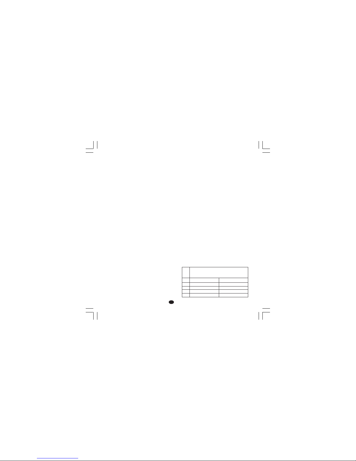
21
FF
FF
F
CARACTERISTIQUES TECHNIQUESCARACTERISTIQUES TECHNIQUES
CARACTERISTIQUES TECHNIQUESCARACTERISTIQUES TECHNIQUES
CARACTERISTIQUES TECHNIQUES
SPECIFICATIONS TECHNIQUESSPECIFICATIONS TECHNIQUES
SPECIFICATIONS TECHNIQUESSPECIFICATIONS TECHNIQUES
SPECIFICATIONS TECHNIQUES
BoîtierBoîtier
BoîtierBoîtier
Boîtier: PC-ABS noir; degré d'auto-extinction: V-0
suivant UL 94.
Protection panneau avantProtection panneau avant
Protection panneau avantProtection panneau avant
Protection panneau avant- Le produit est conçu et
vérifié pour garantir une protection IP 65 (*) et
NEMA 4X pour utilisation à l'abri.
(* les vérifications ont été effectuées conformément
aux standards CEI 70-1 et NEMA 250-1991.
Installation Installation
Installation Installation
Installation : Montage sur panneau
Face arrièreFace arrière
Face arrièreFace arrière
Face arrière:21 bornes à vis (vis M3 pour câbles
de φ 0,25 à φ 2,5 mm
2
ou de AWG 22 à AWG
14) avec les diagrammes de raccordement et les
chapeaux de borne de sécurité.
DimensionsDimensions
DimensionsDimensions
Dimensions: suivant DIN 43700 48 x 96 mm,
profondeur: 89 mm.
MasseMasse
MasseMasse
Masse: 600 g.
AlimentationAlimentation
AlimentationAlimentation
Alimentation:
- de 100V à 240V c.a. 50/60Hz (-15% à + 10%
de la valeur nominale)
- 24 V c.c./c.a. (
+ 10 % de la valeur nominale).
Autoconsommation Autoconsommation
Autoconsommation Autoconsommation
Autoconsommation : 6 VA maxi.
Résistance d'isolementRésistance d'isolement
Résistance d'isolementRésistance d'isolement
Résistance d'isolement: > 100 MΩ suivant IEC
1010 -1.
Rigidité diélectriqueRigidité diélectrique
Rigidité diélectriqueRigidité diélectrique
Rigidité diélectrique: 1500 V mns suivant IEC
1010 - 1.
Intervalle d'échantillonage: Intervalle d'échantillonage:
Intervalle d'échantillonage: Intervalle d'échantillonage:
Intervalle d'échantillonage: 500 ms.
RésolutionRésolution
RésolutionRésolution
Résolution: 30000 comptes
PrécisionPrécision
PrécisionPrécision
Précision:
+ 0,2% v.f.s. + 1 digit @ 25 °C de
température ambiante.
Réjection de mode communRéjection de mode commun
Réjection de mode communRéjection de mode commun
Réjection de mode commun 120 dB à 50/60 Hz.
Réjection de mode normal:Réjection de mode normal:
Réjection de mode normal:Réjection de mode normal:
Réjection de mode normal: 60 dB à 50/60 Hz.
Compatibilité électromagnétique et Compatibilité électromagnétique et
Compatibilité électromagnétique et Compatibilité électromagnétique et
Compatibilité électromagnétique et
normes denormes de
normes denormes de
normes de
sécuritésécurité
sécuritésécurité
sécurité: Cet instrument est marqué CE; il est donc
conforme aux directives 89/336/EEC (standard
harmonisé de référence EN 50081-2 et EN 50082-2),
et aux directives 72/23/EEC et 93/68/EEC
(comme référence à la Norme Générale
Normalisée EN 61010-1).
Catégorie d'installationCatégorie d'installation
Catégorie d'installationCatégorie d'installation
Catégorie d'installation: II
Dérive thermique: Dérive thermique:
Dérive thermique: Dérive thermique:
Dérive thermique: (CJ exclue)
< 400 ppm/°C pour entrée de thermocouple T et de
RTD avec échelle -19.9/99.9°C
< 200 ppm/°C pour les autres entrées.
Température de fonctionnementTempérature de fonctionnement
Température de fonctionnementTempérature de fonctionnement
Température de fonctionnement: de 0 à 50 °C.
Température de stockage: Température de stockage:
Température de stockage: Température de stockage:
Température de stockage: de -20 à + 70 °C
Humidité Humidité
Humidité Humidité
Humidité : de 20 % à 85% RH, sans condensation.
Protections:Protections:
Protections:Protections:
Protections:
1) WATCH DOG circuit pour le restart automatique
2) DIP SWITCH pour la protection des
paramètres de configuration et de calibration.
ENTREESENTREES
ENTREESENTREES
ENTREES
A) A)
A) A)
A)
THERMOCOUPLESTHERMOCOUPLES
THERMOCOUPLESTHERMOCOUPLES
THERMOCOUPLES
Type:Type:
Type:Type:
Type: L -J -K -T -N - °C/°F sélectionnable.
Résistance extérieureRésistance extérieure
Résistance extérieureRésistance extérieure
Résistance extérieure: maxi. 100 Ω avec erreur
maxi. égale à 0,1% de l'étendue de l'échelle
sélectionnée.
Burn out (rupture)Burn out (rupture)
Burn out (rupture)Burn out (rupture)
Burn out (rupture): signalé comme condition de
dépassement d'échelle positif (standard). Au
moyen de contacts on peut sélectionner la
visualisation de dépassement d'échelle négatif.
Soudure froideSoudure froide
Soudure froideSoudure froide
Soudure froide: compsensation automatique de 0
à 50°C.
Précision de la soudure froide Précision de la soudure froide
Précision de la soudure froide Précision de la soudure froide
Précision de la soudure froide : 0.1 °C/°C
Impédance d’entréeImpédance d’entrée
Impédance d’entréeImpédance d’entrée
Impédance d’entrée: > 1MΩ
Calibration: Calibration:
Calibration: Calibration:
Calibration: suivant IEC 584-1 et DIN 43710-1977.
TABLEAU ECHELLES STANDARD
EchelleEchelle
EchelleEchelle
Echelle
0 / + 800 °C
0 / + 800 °C
0 / + 999 °C
0 / + 400 °C
0 / + 999 °C
0 / + 999 °F
0 / + 999 °F
0 / + 999 °F
0 / + 752 °F
0 / + 999 °F
TypeType
TypeType
Type
TCTC
TCTC
TC
LL
LL
L
JJ
JJ
J
KK
KK
K
TT
TT
T
NN
NN
N
Nuovo-1 16/02/2005, 14.1521
Page 49

22
FF
FF
F
ACTIONS DE CONTROLEACTIONS DE CONTROLE
ACTIONS DE CONTROLEACTIONS DE CONTROLE
ACTIONS DE CONTROLE
Action de contrôleAction de contrôle
Action de contrôleAction de contrôle
Action de contrôle: PID ou SMART
Bande proportionnelle :Bande proportionnelle :
Bande proportionnelle :Bande proportionnelle :
Bande proportionnelle : de 1.0 (si on utilise une
seule sortie de régulation) ou 1,5% (si on utilise
deux sorties de régulation) à 99,9% de l'étendue
de l'échelle d'entrée.
Quand Pb=0, l'action de contrôle devient ON/OFF.
Hystérésis Hystérésis
Hystérésis Hystérésis
Hystérésis (pour contrôle ON/OFF ): de 0,1% à
10,0% de l'étendue de l'échelle d'entrée.
Temps intégralTemps intégral
Temps intégralTemps intégral
Temps intégral: de 10" à 20'; résolution 10
secondes. En programmant une valeur supérieure
à 20 minutes, l'action intégrale est exclue.
Temps dérivé Temps dérivé
Temps dérivé Temps dérivé
Temps dérivé : de 0 à 9'59".
Précharge de l'action intégrale:Précharge de l'action intégrale:
Précharge de l'action intégrale:Précharge de l'action intégrale:
Précharge de l'action intégrale:
- de 0 à100,0 % pour une sortie de régulation
- de -100 à 100 % pour deux sorties de régulation
Temps de cycle de la sortie principale: Temps de cycle de la sortie principale:
Temps de cycle de la sortie principale: Temps de cycle de la sortie principale:
Temps de cycle de la sortie principale: de 1 à
200 s
Temps de cycle de la sortie de refroidisse-Temps de cycle de la sortie de refroidisse-
Temps de cycle de la sortie de refroidisse-Temps de cycle de la sortie de refroidisse-
Temps de cycle de la sortie de refroidissementment
mentment
ment: de 1 à 200 s.
Gain relatif de l'action de refroidissementGain relatif de l'action de refroidissement
Gain relatif de l'action de refroidissementGain relatif de l'action de refroidissement
Gain relatif de l'action de refroidissement: de
0,20 à 1,00.
NOTE: NOTE:
NOTE: NOTE:
NOTE: on peut limiter les paramètres PB, TI, TD
et RCG quand la fonction SMART est autorisée.
Superposition de la bande morte:Superposition de la bande morte:
Superposition de la bande morte:Superposition de la bande morte:
Superposition de la bande morte: de -20% à 50%
SORTIES DE REGULATIONSORTIES DE REGULATION
SORTIES DE REGULATIONSORTIES DE REGULATION
SORTIES DE REGULATION
Type: Type:
Type: Type:
Type: temps proportionnel
Temps de mise à jour: Temps de mise à jour:
Temps de mise à jour: Temps de mise à jour:
Temps de mise à jour: 500 ms
Résolution de la sortie:Résolution de la sortie:
Résolution de la sortie:Résolution de la sortie:
Résolution de la sortie: 1% de l'étendue de
l'échelle.
Action: Action:
Action: Action:
Action: directe ou inverse programmable.
Limiteur de la puissance de sortie:Limiteur de la puissance de sortie:
Limiteur de la puissance de sortie:Limiteur de la puissance de sortie:
Limiteur de la puissance de sortie:
- pour une sortie de régulation : de 0,0 à 100,0 % .
- pour deux sorties de régulation: de -100,0 à +
100,0%.
Cette fonction peut être validée à la mise en service
de l'instrument (pour éviter des chocs thermiques ou
de préchauffer l'installation).
B) RTDB) RTD
B) RTDB) RTD
B) RTD (Résistance Temperature Detector)
Type: Type:
Type: Type:
Type: Pt 100 à 3 fils
Courant: Courant:
Courant: Courant:
Courant: 135 µA
Résistance de ligne: Résistance de ligne:
Résistance de ligne: Résistance de ligne:
Résistance de ligne: Compensation automatique
jusqu'à 20 Ω/fil avec:
- erreur < ± 0,1% de l'étendue de l'échelle
d'entrée pour l'échelle -19,9 à 99,9°C.
- erreur non mesurable pour toutes les autres
échelles.
Unités techniques:Unités techniques:
Unités techniques:Unités techniques:
Unités techniques: °C ou °F programmables.
Burn-out (rupture)Burn-out (rupture)
Burn-out (rupture)Burn-out (rupture)
Burn-out (rupture): échelle maxi.
NOTENOTE
NOTENOTE
NOTE: un contrôle spécial produit un signal
de dépassement d'échelle positif quand la
résistance d'entrée est inférieure à 15Ω.
CalibrationCalibration
CalibrationCalibration
Calibration: suivant DIN 43760
TABLEAU ECHELLES STANDARD
C) ENTREE DE TRANSFORMATEURC) ENTREE DE TRANSFORMATEUR
C) ENTREE DE TRANSFORMATEURC) ENTREE DE TRANSFORMATEUR
C) ENTREE DE TRANSFORMATEUR
AMPEREMETRIQUEAMPEREMETRIQUE
AMPEREMETRIQUEAMPEREMETRIQUE
AMPEREMETRIQUE
Courant d'entréeCourant d'entrée
Courant d'entréeCourant d'entrée
Courant d'entrée: 50 mA c.a.
Visualisation Visualisation
Visualisation Visualisation
Visualisation : peut être sélectionnée entre 10, 25,
50 ou 100 A.
RésolutionRésolution
RésolutionRésolution
Résolution:
- pour la capacité 10 A : 0,1 A.
- pour les autres capacités : 1 A.
Période activePériode active
Période activePériode active
Période active:
- pour sortie à relais : NO ou NC programmable
- pour sortie commande SSR : niveau logique 1
ou 0 programmable.
Durée mini. de la période activeDurée mini. de la période active
Durée mini. de la période activeDurée mini. de la période active
Durée mini. de la période active: 50 ms.
Type deType de
Type deType de
Type de
RTDRTD
RTDRTD
RTD
RTD Pt 100
RTD Pt 100
-199 - +500 °C
-19.9 - +99.9 °C
Echelle de mesureEchelle de mesure
Echelle de mesureEchelle de mesure
Echelle de mesure
-199 - +999 °F
-----
Nuovo-1 16/02/2005, 14.1522
Page 50

23
FF
FF
F
SORTIESSORTIES
SORTIESSORTIES
SORTIES
a) Sortie à relais avec contact SPDT;
Capacité du contact 3A/250V c.a. sur charge
résistive
b) Tension logique pour SSR.
Etat logique 1: 24V
+20% @1mA.
14V
+20% @20mA
Etat logique 0:<0.5V
Action de la sortieAction de la sortie
Action de la sortieAction de la sortie
Action de la sortie: directe/inverse
programmable.
La sélection entre la sortie à relais ou la tension
logique est effectuée au moyens d'un pontet et
d'un paramètre de configuration.
Sortie 2 - Refroidissement ou alarme 1Sortie 2 - Refroidissement ou alarme 1
Sortie 2 - Refroidissement ou alarme 1Sortie 2 - Refroidissement ou alarme 1
Sortie 2 - Refroidissement ou alarme 1
a) Sortie à relais avec contact SPST;
Capacité du contact 2A/250V c.a. sur charge
résistive
b) Tension logique pour SSR.
Etat logique 1: 24V
+20% @1mA.
14V
+20% @20mA
Etat logique 0:<0.5V
La sélection entre la sortie à relais ou la tension
logique est effectuée au moyens de pontets.
ALARMESALARMES
ALARMESALARMES
ALARMES
L'instrument peut être pourvu de deux alarmes
indépendantes.
L'alarme 1 est une fonction standard de cet
appareil et l'alarme 2 est une option. Chaque
alarme peut être configurée de la façon suivante:
Alarmes de procédéAlarmes de procédé
Alarmes de procédéAlarmes de procédé
Alarmes de procédé
Dialogue utilisateurDialogue utilisateur
Dialogue utilisateurDialogue utilisateur
Dialogue utilisateur: maximum ou minimum.
Seuil: Seuil:
Seuil: Seuil:
Seuil: programmable en unités techniques à l'intérieur
de l'échelle d'entrée (P3 - P2).
Alarmes de bandeAlarmes de bande
Alarmes de bandeAlarmes de bande
Alarmes de bande
Dialogue utilisateurDialogue utilisateur
Dialogue utilisateurDialogue utilisateur
Dialogue utilisateur: à l'intérieur ou à l'extérieur
de la bande.
SeuilSeuil
SeuilSeuil
Seuil: programmable de 0 à 500 unités.
Alarmes de déviationAlarmes de déviation
Alarmes de déviationAlarmes de déviation
Alarmes de déviation
Dialogue utilisateurDialogue utilisateur
Dialogue utilisateurDialogue utilisateur
Dialogue utilisateur: en-dessous et au-dessus
de la valeur programmée.
SeuilSeuil
SeuilSeuil
Seuil: programmable de - 500 à +500 unités.
ActionAction
ActionAction
Action: directe ou inverse programmable
Résolution du seuilRésolution du seuil
Résolution du seuilRésolution du seuil
Résolution du seuil: 1 digit.
Hystérésis d'alarmeHystérésis d'alarme
Hystérésis d'alarmeHystérésis d'alarme
Hystérésis d'alarme: programmable de 0,1 % à
10,0 % de l'étendue de l'échelle d'entrée.
Acquit des alarmes:Acquit des alarmes:
Acquit des alarmes:Acquit des alarmes:
Acquit des alarmes: automatique ou manuel
programmable pour chaque alarme.
Masquage des alarmesMasquage des alarmes
Masquage des alarmesMasquage des alarmes
Masquage des alarmes: chaque alarme peut
être programmée avec ou sans le masquage
Cette fonction permet d'éliminer de fausses
indications d'alarme à la mise en service ou après
la modification du point de consigne.
Indication d'alarmeIndication d'alarme
Indication d'alarmeIndication d'alarme
Indication d'alarme: la LED AL1/COOL est allumée
quand l'alarme est en état ON.
La LED AL2/HBD suit les indications du tableau
suivant:
HBD AL2 LE D
état état AL2/HBD
0 0 OFF
01 ON
1 0 clignote lentement
1 1 clignote rapidement
Sorties des alarmes:Sorties des alarmes:
Sorties des alarmes:Sorties des alarmes:
Sorties des alarmes:
1) alarme 1: Sortie à relais avec contact SPST;
Capacité du contact 3A/250V c.a. sur
charge résistive.
2) alarme 2: Sortie à relais avec contact SPST;
Capacité du contact 2A/250V c.a. sur charge
résistive.
NOTENOTE
NOTENOTE
NOTE: les fonctions Alarme 2 et HBD sont
en OR sur la sortie 2.
Nuovo-1 16/02/2005, 14.1523
Page 51

24
FF
FF
F
ALARME DE DYSFONCTIONNEMENT DEALARME DE DYSFONCTIONNEMENT DE
ALARME DE DYSFONCTIONNEMENT DEALARME DE DYSFONCTIONNEMENT DE
ALARME DE DYSFONCTIONNEMENT DE
LA CHARGELA CHARGE
LA CHARGELA CHARGE
LA CHARGE
Cette entrée facultative permet de mesurer, au moyen
du transformateur ampèremétrique, le courant
circulant dans la charge principale pendant la période
active de la sortie 1 et de créer une indication
d'alarme si cette valeur est inférieure à un seuil
programmable (la sortie d'alarme est en OR avec
l'alarme 2).
Résolution du seuilRésolution du seuil
Résolution du seuilRésolution du seuil
Résolution du seuil: 1 digit.
Hystérésis d'alarmeHystérésis d'alarme
Hystérésis d'alarmeHystérésis d'alarme
Hystérésis d'alarm e: 1 % de l'échelle sélectionnée
Indication d'alarmeIndication d'alarme
Indication d'alarmeIndication d'alarme
Indication d'alarme: La LED ’AL2 HB" clignote sur
ON.
FONCTIONS SPECIALESFONCTIONS SPECIALES
FONCTIONS SPECIALESFONCTIONS SPECIALES
FONCTIONS SPECIALES
Invalidation du signal de sortieInvalidation du signal de sortie
Invalidation du signal de sortieInvalidation du signal de sortie
Invalidation du signal de sortie
Cette fonction permet de forcer sur zéro la
puissance des sorties de régulation et d'invalider
l'algorithme de contrôle et la fonction des
alarmes. On diminue ainsi la puissance de
l'élément de régulation tandis que l'instrument
agit comme un simple indicateur.
On peut ainsi vérifier le comportement de la
variable même quand la charge n'est plus active.
Quand l'action de régulation est réactivée,
l'instrument se comporte de la façon suivante:
- la composante intégrale du signal de sortie est
mise à zéro,
- la fonction soft start et le masquage des alarmes
sont réactivés.
LAMP TESTLAMP TEST
LAMP TESTLAMP TEST
LAMP TEST
Cette fonction permet de vérifier le
fonctionnement de l'indicateur.
ENTRETIENENTRETIEN
ENTRETIENENTRETIEN
ENTRETIEN
1) COUPER LA TENSION A L’APPAREIL
(alimentation, sorties à relais, etc.)
2) Enlever l’instrument de son boîtier
3) En utilisant un aspirateur ou un jet d’air comprimé
à basse pression (maxi. 3 kg/cm2), enlever les
dépôts de poussière et de saleté dans les fissures
de ventilation et sur les circuits en faisant attention
à ne pas endommager les composants.
4) Pour nettoyer les parties extérieures en plastique
ou en caoutchouc, utiliser exclusivement un
chiffon propre et légèrement imbibé de:
- alcool éthylique (pur ou dénaturé) [C
2H5
OH]
- alcool isopropylique (pur ou dénaturé) [(CH3)
2
CHOH]
- eau (H2O)
5) Contrôler qu’aucune borne n’est desserrée
6) Avant de rebrancher l’instrument dans son
boîtier, vérifier que l’appareil soit parfaitement
sec.
7) Rebrancher l’appareil et mettre sous tension.
Nuovo-1 16/02/2005, 14.1524
Page 52
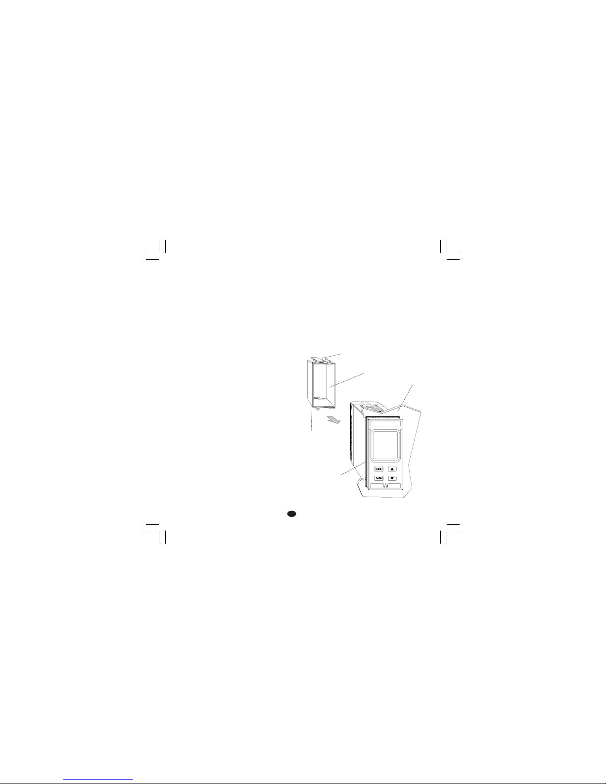
1
DD
DD
D
Fronttafel
Strebe
Schraube
Schraube
Dichtung
Abb. 1
MONTAGEMONTAGE
MONTAGEMONTAGE
MONTAGE
Für die Montage eine Stelle wählen, die folgende
Merkmale aufweist:
1) leichte Zugänglichkeit auch an der Rückseite
2) keinen Vibrationen oder Stößen ausgesetzt
3) keinen korrosiven Gasen ausgesetzt
(Schwefelgas, Ammoniak, usw.)
4) keine Wasser oder andere Flüssigkeiten in der
näheren Umgebung
5) Umgebungstemperatur zwischen 0°C und
50 °C liegen.
6) Relative Feuchtigkeit zwischen 20 und 85% RH
und kein Kondenswasser.
Das Gerät kann auf eine bis zu 15 mm dicke
Fronttafel montiert werden, in die ein rechteckiger
Ausschnitt mit den Maßen 45 x 92 mm praktiziert
wurde.
Abmessungen und Fronttafelausschnitt siehe Abb.2.
Die Oberflächenrauheit der Tafel muß besser als 6,3
µmm sein.
Das Gerät ist mit einer Gummidichtung für Fronttafeln
ausgerüstet (von 50 bis 60 Sh).
Zur Gewährleistung der Schutzarten IP65 und NEMA
4, die mit dem Gerät gelieferte Dichtung zwischen
das Gerät und die Tafel einfügen (siehe Abbildung 1).
Bei der Befestigung des Geräts an der Tafel wie folgt
vorgehen:
1) Die Dichtung an dem Gehäuse des Geräts
anbringen.
2) Das Gerät in den Ausschnitt einsetzen.
3) Das Gerät gut an der Tafel anliegend festhalten
und die Befestigungsstrebe einfügen.
4) Mit einem Schraubenzieher die Schrauben mit
einem Anziehmoment zwischen 0,3 und 0,4 Nm
festziehen.
TMS-3-01.pmd 16/02/2005, 14.221
Page 53
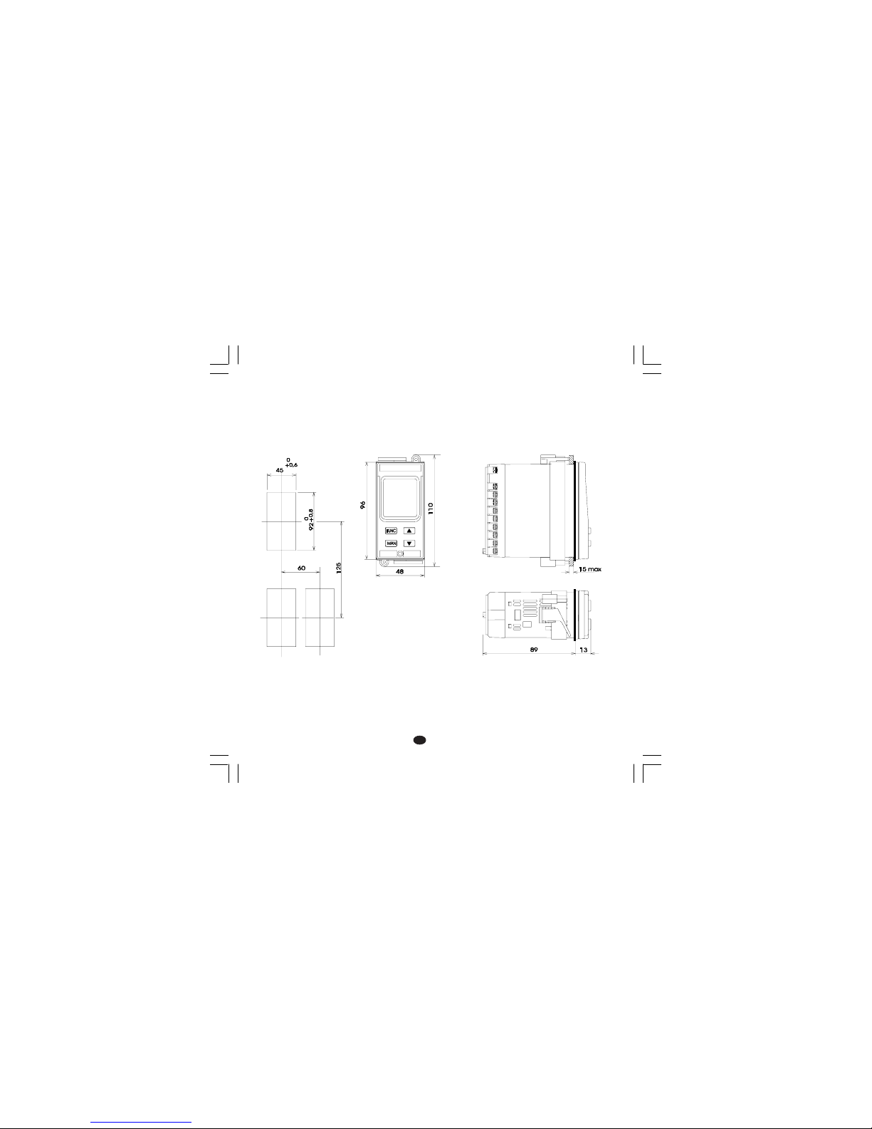
2
DD
DD
D
ABMESSUNGEN UNDABMESSUNGEN UND
ABMESSUNGEN UNDABMESSUNGEN UND
ABMESSUNGEN UND
FRONTTAFELAUSSCHNITTFRONTTAFELAUSSCHNITT
FRONTTAFELAUSSCHNITTFRONTTAFELAUSSCHNITT
FRONTTAFELAUSSCHNITT
Add. 2
TMS-3-01.pmd 16/02/2005, 14.222
Page 54
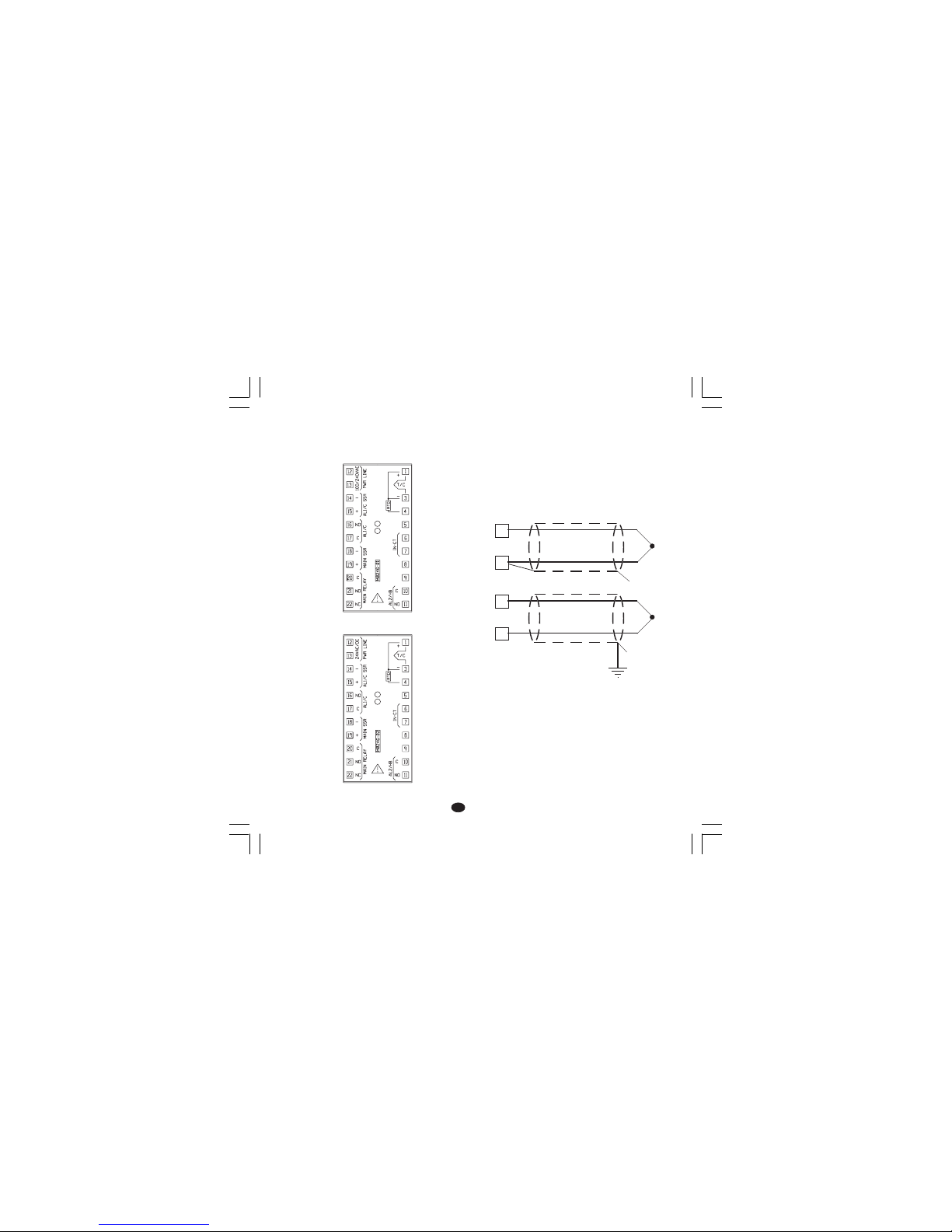
3
DD
DD
D
ELEKTRISCHE ANSCHLÜSSEELEKTRISCHE ANSCHLÜSSE
ELEKTRISCHE ANSCHLÜSSEELEKTRISCHE ANSCHLÜSSE
ELEKTRISCHE ANSCHLÜSSE
Die Anschlüsse müssen durchgeführt werden,
nachdem das Gehäuse des Geräts vorschriftsmäßig auf der Tafel montiert wurde.
Abb.3.A ANSCHLUSSKLEMMEN (für 100/240 V
AC Ausführungen)
Abb.3.B ANSCHLUSSKLEMMEN (für 24 V AC/
DC Ausführungen)
A) MESSEINGÄNGEA) MESSEINGÄNGE
A) MESSEINGÄNGEA) MESSEINGÄNGE
A) MESSEINGÄNGE
ANMERKUNG:ANMERKUNG:
ANMERKUNG:ANMERKUNG:
ANMERKUNG: Externe Komponenten (z.Bsp.:
Zener-Barrieren) zwischen dem Fühler und den
Eingangsanschlüssen des Geräts können
Meßfehler bewirken, die durch einen zu hohen
oder nicht ausbalancierten Widerstand oder
durch Leckströme verursacht werden.
EINGANG FÜR THERMOELEMENTEINGANG FÜR THERMOELEMENT
EINGANG FÜR THERMOELEMENTEINGANG FÜR THERMOELEMENT
EINGANG FÜR THERMOELEMENT
Abb.4 ANSCHLUSS DES THERMOELEMENTS
ANMERKUNGEN:ANMERKUNGEN:
ANMERKUNGEN:ANMERKUNGEN:
ANMERKUNGEN:
1) Die Signalkabel nicht parallel oder in der Nähe
von Leistungskabeln oder Störquellen
verlegen.
2) Für den Anschluß des Thermoelements ein
geeignetes, vorzugsweise abgeschirmtes
Kompensations-/Erweiterungskabel
verwenden.
3) Bei Verwendung eines Abschirmkabels, den
Schutzschirm nur an einem Ende erden.
1
3
+
_
1
3
+
_
Schutzschirm
Schutzschirm
TMS-3-01.pmd 16/02/2005, 14.223
Page 55
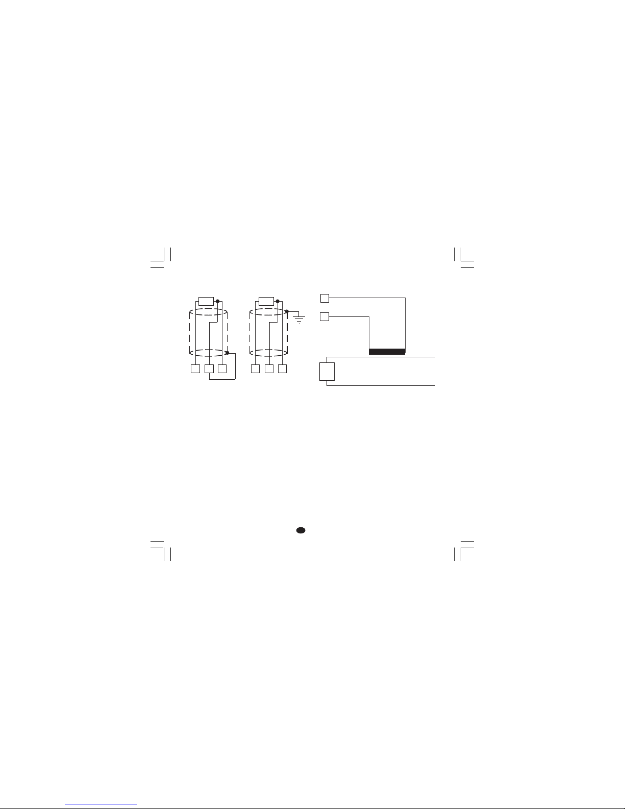
4
DD
DD
D
EINGANG FÜREINGANG FÜR
EINGANG FÜREINGANG FÜR
EINGANG FÜR
WIDERSTANDSTHERMOMETERWIDERSTANDSTHERMOMETER
WIDERSTANDSTHERMOMETERWIDERSTANDSTHERMOMETER
WIDERSTANDSTHERMOMETER
Abb.5 ANSCHLUSS DES
WIDERSTANDSTHERMOMETERS
ANMERKUNGEN:ANMERKUNGEN:
ANMERKUNGEN:ANMERKUNGEN:
ANMERKUNGEN:
1) Die Signalkabel nicht parallel oder in der
Nähe von Leistungskabeln oder Störquellen
verlegen.
2) Auf den Leitungswiderstand achten. Ein
übermäßig hoher Leitungswiderstand (über 20
Ω/Leiter) kann Meßfehler bewirken.
3) Bei Verwendung eines Abschirmkabels, den
Schutzschirm nur an einem Ende erden.
4) Die 3 Leiter müssen den gleichen Widerstand
haben.
B) EINGANG VON STROMWANDLERB) EINGANG VON STROMWANDLER
B) EINGANG VON STROMWANDLERB) EINGANG VON STROMWANDLER
B) EINGANG VON STROMWANDLER
Abb.6 ANSCHLUSS DES STROMWANDLERS
Anmerkung:
1) Der Eingangswiderstand beträgt 10Ω.
2) Der Eingangsspitzenstrom beträgt 50 mA
(50/60 Hz).
4
RTD
13 4
RTD
13
6
7
Stromwandler
Last
TMS-3-01.pmd 16/02/2005, 14.224
Page 56
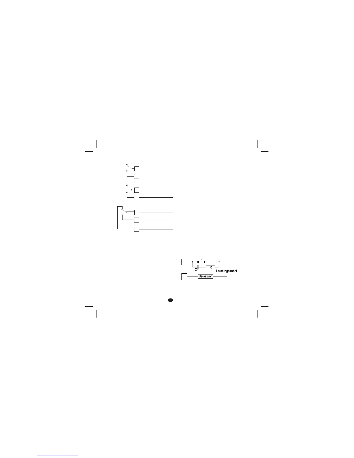
5
DD
DD
D
2) Für den Netzanschluß Kabel Nr.16 AWG oder
mit größerem Querschnitt verwenden, die für
eine Temperatur von mindestens 75°C
geeignet sind.
3) Nur Kupferleiter verwenden.
4) Die Leistungskabel nicht parallel oder in der
Nähe von Signalkabeln verlegen.
5) Der Relais-und der Festkörperrelaisausgang
sind beide verfügbar. Bei Verwendung des
Relaisausgangs muß der Festkörperrelaisausgang (SSR-Ausgang) deaktiviert werden
(siehe Kapitel “Hardware-Voreinstellungen).
Die folgenden Empfehlungen dienen zur
Vermeidung schwerwiegender Probleme durch
die Verwendung des Ausgangs 3 oder der NCKontakte des Ausgangs 1 für die Vorsteuerung
induktiver Belastungen.
INDUKTIVE BELASTUNGENINDUKTIVE BELASTUNGEN
INDUKTIVE BELASTUNGENINDUKTIVE BELASTUNGEN
INDUKTIVE BELASTUNGEN
Bei der Umschaltung induktiver Belastungen
können Einschwingzustände und Störungen
entstehen, die die Leistungen des Geräts
beeinträchtigen können.
Analoge Probleme können durch die
Umschaltung von Belastungen mittels eines
externen, zum Ausgang des Geräts in Reihe
geschalteten Kontakts, entstehen.
Abb.8 EXTERNER, ZUM AUSGANG DES
GERÄTS IN REIHE GESCHALTETER KONTAKT
C) RELAISAUSGÄNGEC) RELAISAUSGÄNGE
C) RELAISAUSGÄNGEC) RELAISAUSGÄNGE
C) RELAISAUSGÄNGE
Abb.7 ANSCHLUSS DER RELAISAUSGÄNGE
Der Ausgang 2 und der NO-Kontakt des Ausgangs
1 sind mittels Varistoren gegen Belastungen
geschützt, deren induktive Komponente bis zu 0,5
A beträgt.
Die Belastbarkeit des dem Ausgang 1
entsprechenden Kontakts, beträgt 3A/250 V AC
bei ohmscher Belastung.
Die Belastbarkeit der den Ausgängen 2 und 3
entsprechenden Kontakte beträgt 2 A/250V AC bei
ohmscher Belastung.
Die Anzahl der Umschaltungen ist gleich 1x10
5
der
spezifizierten Belastbarkeit.
ANMERKUNGEN:ANMERKUNGEN:
ANMERKUNGEN:ANMERKUNGEN:
ANMERKUNGEN:
1) Zur Vermeidung elektrischer Schläge, die
Versorgung erst anschließen, nachdem alle
anderen Anschlüsse vorgenommen wurden.
22
21
OUT 1
20
C
NO
NC
10
11
AL2/HBD
(OUT 3)
C - OUT 3
NO - OUT 3
16
17
AL1/COOL
(OUT 2)
OUT 2
C - OUT 2
NO/NC
[siehe Abb.11 (J303)]
TMS-3-01.pmd 16/02/2005, 14.225
Page 57
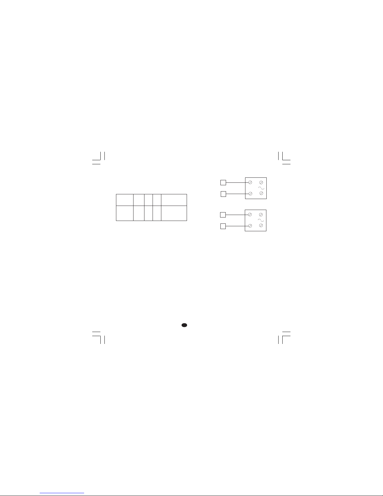
6
DD
DD
D
In diesen Fällen wird empfohlen, parallel zum
externen Kontakt (oder an den internen, nicht
geschützten Kontakt) einen RC-Filter
anzuschließen wie in Abb.8 gezeigt.
Der Wert der Kapazität (C) und des Widerstands
(R) sind in der folgenden Tabelle angegeben.
In allen Fällen müssen die an die Relaisausgänge
angeschlossenen Kabel soweit wie möglich von
den Signalkabeln entfernt gehalten werden.
D) LOGIKAUSGANG FÜR DIE SSR-STEUERUNGD) LOGIKAUSGANG FÜR DIE SSR-STEUERUNG
D) LOGIKAUSGANG FÜR DIE SSR-STEUERUNGD) LOGIKAUSGANG FÜR DIE SSR-STEUERUNG
D) LOGIKAUSGANG FÜR DIE SSR-STEUERUNG
Abb. 9 ANSCHLUSS FÜR DIE
VORSTEUERUG VON
HALBLEITERRELAIS
Dieser Ausgang ist zeitproportional.
Logikstatus 0:Logikstatus 0:
Logikstatus 0:Logikstatus 0:
Logikstatus 0: Vout < 0,5 V DC
Logikstatus 1:Logikstatus 1:
Logikstatus 1:Logikstatus 1:
Logikstatus 1: Stromspitze = 20 mA.
- 14 V ± 20% @ 20 mA
- 24 V ± 20% @ 1 mA.
ANMERKUNGENANMERKUNGEN
ANMERKUNGENANMERKUNGEN
ANMERKUNGEN:
1) Diese Ausgange sind NICHT isoliert. Eine
verstärkte galvanische oder optoisolierte
Trennung zwischen der Lastversorgung und
dem Ausgang muß gemäß den CE-Richtlinien
z.B. durch ein Halbleiterrelais mit verstärktem
isoliertem Eingang sichergestellt werden.
2) Der Relais-und der Halbleiterrelaisausgang
sind beide verfügbar. Bei Verwendung des
Relaisausgangs muß der
Halbleiterrelaisausgang (SSR-Ausgang)
deaktiviert werden (siehe Kapitel “HardwareVoreinstellungen).
BELASTUNG
(mA)
<40 mA
<150 mA
<0.5 A
C
(µF)
0.047
0.1
0.33
R
(Ω)
100
22
47
P.
(W)
1/2
2
2
BETRIEBS-
SPANNUNG
260 V AC
260 V AC
260 V AC
_
+
_
+
_
_
+
+
18
19
14
15
OUT 1
OUT 2
(AL1/Cool.)
Halbleiterrelais
Halbleiterrelais
TMS-3-01.pmd 16/02/2005, 14.226
Page 58

7
DD
DD
D
13
R (S,T)
R (S,T)
N
12
Netz
von 100 V bis 240 V AC (50/60 Hz)
oder 24 V AC/DC
N
E) VERSORGUNGE) VERSORGUNG
E) VERSORGUNGE) VERSORGUNG
E) VERSORGUNG
Abb.10 ANSCHLUSS AN DAS STROMNETZ
ANMERKUNGEN:ANMERKUNGEN:
ANMERKUNGEN:ANMERKUNGEN:
ANMERKUNGEN:
1) Vor dem Anschluß des Geräts an das
Stromnetz, sich vergewissern, das die
Leitungsspannung mit der auf dem Kennschild
des Geräts angegebenen Spannung
übereinstimmt.
2) Zur Vermeidung elektrischer Schläge, die
Versorgung erst anschließen, nachdem alle
anderen Anschlüsse vorgenommen wurden.
3) Für den Netzanschluß Kabel Nr.16 AWG oder
mit größerem Querschnitt verwenden, die für
eine Temperatur von mindestens 75°C
geeignet sind.
4) Nur Kupferleiter verwenden.
5) Die Signalkabel nicht parallel oder in der Nähe
von Leistungskabeln oder Störquellen
verlegen.
6) Bei der 24 V DC-Versorgung hat die Polarität
keine Bedeutung.
7) Die Versorgungskreise sind NICHT durch eine
Sicherung geschützt. Es wird daher
empfohlen, einen externen Schutz mit
folgenden Merkmalen vorzusehen:
Sicherung Typ T, 1 A, 250 V.
Im Fall einer Beschädigung der Sicherung wird
empfohlen, den gesamten Versorgungskreis
überprüfen zu lassen. Zu diesem Zweck sollte
das Gerät an den Lieferanten gesandt werden.
8) Gemäß den Sicherheitsvorschriften für ständig
an das Stromnetz angeschlossene Geräte sind
folgende Einrichtungen zu installieren:
- Ein Schalter oder Auftrenner in der
elektrischen Anlage des Gebäudes;
- Der Auftrenner muß in unmittelbarer Nähe des
Gerätes an einer für das Bedienungspersonal
leicht zugänglichen Stelle installiert werden.
- Der Schalter muß als Trennvorrichtung des
Gerätes gekennzeichnet werden.
ANMERKUNG:ANMERKUNG:
ANMERKUNG:ANMERKUNG:
ANMERKUNG: Ein Schalter oder Auftrenner kann
mehrere Geräte steuern.
9) Den eventuell für die Netzversorgung vorgesehenen Nulleiter an den Endverschluß 12
anschließen.
TMS-3-01.pmd 16/02/2005, 14.227
Page 59
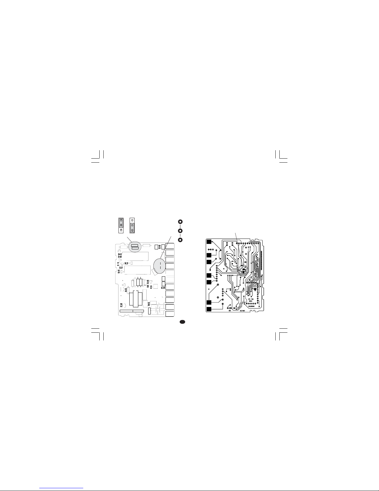
8
DD
DD
D
HARDWARE-VOREINSTELLUNGENHARDWARE-VOREINSTELLUNGEN
HARDWARE-VOREINSTELLUNGENHARDWARE-VOREINSTELLUNGEN
HARDWARE-VOREINSTELLUNGEN
1) Das Instrument aus dem Gehäuse ziehen.
2) Für die Ausgänge 1 und 2 mit Hilfe der
Kodierstecker J 304 und J305 die Art des
gewünschten Ausgangs wählen.
J304 (AL 1, Kühlen) 1-2 = SSR 2-3 = Relais
J305 (Heizausgang) 1-2 = SSR 2-3 = Relais
3) Für den Ausgang 2 kann der verwendete Kontakt
(NO oder NC) mittels J303 gewählt werden.
J303 (AL 1, Kühlen) 1-2 = Out NO 2-3 = Out NC
Anmerkung:Anmerkung:
Anmerkung:Anmerkung:
Anmerkung: J303 ist ein Lötstützpunkt und wird
auf der Lötseite ausgeführt.
FÜHLERBRUCHERFASSUNGFÜHLERBRUCHERFASSUNG
FÜHLERBRUCHERFASSUNGFÜHLERBRUCHERFASSUNG
FÜHLERBRUCHERFASSUNG
Dieses Gerät ist in der Lage, für TC-oder RTDEingänge einen offenen Meßkreis zu erfassen.
Die Öffnung des RTD-Meßkreises wird als
Overrange-Bedingung (Bereichsüberschreitung)
angezeigt.
Für den Thermoelement-Eingang kann die Art der
Anzeige hingegen gewählt werden: OverrangeAnzeige (Standard) durch Schließung von CH2
und Öffnung von SH2.
Underrange-Anzeige durch Öffnung von CH2 und
Schließung von SH2.
Beide Plätze befinden sich auf der Lötseite der
CPU-Karte (siehe Zeichnung)
Abb. 12
1
1
1
23
4
+
-
+
B
C
E
I
1
3
4
7
1
1
XY00
I
1
2
3
12
3
45
12
345
J301
J302
L305
R301
R303
D
3
0
5
C308
C306
C307
R305
C312
C310
D307
R308
C309
PZ12
PZ13
PZ14
PZ15
PZ16
PZ19
PZ20
PZ21
PZ22
R307
R306
Q302
U302
TR301
J304
J305
Y301
D306
D308
D304
U301
PZ18
PZ17
C301
C
3
0
4
J303
C303
C311
C302
C305
C314
C313
L304
L301
L303
L302
R309
R310
R312
R314
R311
R302
R304
R313
Q303
Q305
D302
Q301
Q304
D301
D310
K302
K301
J 303
1
3
J304 J305
1
Abb. 11
CH2
SH2
TMS-3-01.pmd 16/02/2005, 14.228
Page 60
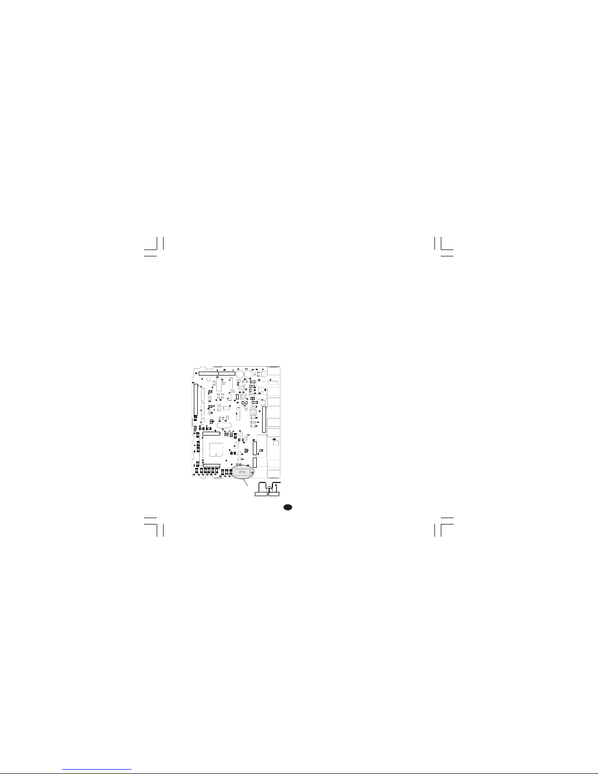
9
DD
DD
D
ALLGEMEINE ANMERKUNGENALLGEMEINE ANMERKUNGEN
ALLGEMEINE ANMERKUNGENALLGEMEINE ANMERKUNGEN
ALLGEMEINE ANMERKUNGEN
zur Konfigurationzur Konfiguration
zur Konfigurationzur Konfiguration
zur Konfiguration
FUNC = Speichern der eingestellten Werte und
Anwahl des darauf folgenden
Parameters.
SMRT = Rückwärtstasten der Parameter,
jedoch keine Speicherung.
= Vergrößern des Werts des
angewählten Parameters
= Verkleinern des Werts des
angewählten Parameters
KONFIGURATIONKONFIGURATION
KONFIGURATIONKONFIGURATION
KONFIGURATION
1) Das Instrument aus dem Gehäuse ziehen.
2) Den internen Hakenschalter V2 öffnen (siehe
die untenstehende Abbildung.)
Abb.13
3) Das Instrument in das Gehäuse zurückschieben.
4) Das Instrument mit Strom versorgen.Das obere
Display zeigt “CnF” an.
ACHTUNG: ACHTUNG:
ACHTUNG: ACHTUNG:
ACHTUNG: Falls das Gerät “CAL” anzeigt,
sofort die Taste
drücken und zur Konfiguration
zurückkehren.
5) Die Taste FUNC drücken. Das untere Display
zeigt den Code des angewählten Parameters
an, während auf dem oberen Display der
eingestellte Wert erscheint.
P1 - Art des Eingangs und StandardmeßbereichP1 - Art des Eingangs und Standardmeßbereich
P1 - Art des Eingangs und StandardmeßbereichP1 - Art des Eingangs und Standardmeßbereich
P1 - Art des Eingangs und Standardmeßbereich
0 = TC Art L Bereich 0 / +800 °C
1 = TC Art J Bereich 0 / +800 °C
2 = TC Art K Bereich 0 / +999 °C
3 = TC Art N Bereich 0 / +999 °C
4 = RTD Art Pt 100 Bereich -199/+500 °C
5 = RTD Art Pt 100 Bereich -19.9/+99.9 °C
6 = TC Art T Bereich 0 / +400 °C
8 = TC Art L Bereich 0 / +999 °F
9 = TC Art J Bereich 0 / +999 °F
10 = TC Art K Bereich 0 / +999 °F
11 = TC Art N Bereich 0 / +999 °F
12 = RTD Art Pt 100 Bereich -199 / +999 °F
13 = TC Art T Bereich 0 / +752 °F
TC = Thermoelement
RTD = Widerstandsthermometer
P2 = AnfangswertP2 = Anfangswert
P2 = AnfangswertP2 = Anfangswert
P2 = Anfangswert
Nicht verfügbar, wenn P1 = 5.
Der Anfangswert wird vom Algorithmus PID benutzt,
um die Breite des Arbeitsbereichs zu berechnen.
P2 kann innerhalb des mittels P1 eingestellten
Eingangsbereichs programmiert werden.
Bei einer Änderung des Parameters P2, ordnet
das Gerät dem Parameter rL automatisch den
neuen Wert von P2 zu.
V2
TMS-3-01.pmd 16/02/2005, 14.229
Page 61

10
DD
DD
D
P3 = EndwertP3 = Endwert
P3 = EndwertP3 = Endwert
P3 = Endwert
Nicht verfügbar, wenn P1 = 5.
Der Endwert wird vom Algorithmus PID benutzt, um
die Breite des Arbeitsbereichs zu berechnen.
P3 kann innerhalb des mittels P1 eingestellten
Eingangsbereichs programmiert werden.
Bei einer Änderung des Parameters P3, ordnet das
Gerät dem Parameter rH automatisch den neuen
Wert von P3 zu.
ANMERKUNG:ANMERKUNG:
ANMERKUNG:ANMERKUNG:
ANMERKUNG: Die Breite des eingestellten
Arbeitsbereichs (P3 - P2) muß über den folgenden
Werten liegen oder gleich sein:
- 300 °C oder 600 °F für TC-Eingang;
- 100 °C oder 200 °F für RTD-Eingang.
P4 = Konfiguration der AusgängeP4 = Konfiguration der Ausgänge
P4 = Konfiguration der AusgängeP4 = Konfiguration der Ausgänge
P4 = Konfiguration der Ausgänge
H = Heizen
HC = Heizen/Kühlen
P5 = P5 =
P5 = P5 =
P5 =
Art des HeizausgangsArt des Heizausgangs
Art des HeizausgangsArt des Heizausgangs
Art des Heizausgangs
rEL = Relaisausgang
SSr = Ausgang für SSR.
ANMERKUNG:ANMERKUNG:
ANMERKUNG:ANMERKUNG:
ANMERKUNG:
Bei Einstellung P5 = rEL, wird der Parameter C
auf einen Wert von 20
Sekunden modifiziert.
Bei Einstellung P5 = SSr, wird der Parameter C
auf einen Wert von 2
Sekunden modifiziert.
P6 = Art des KühlausgangsP6 = Art des Kühlausgangs
P6 = Art des KühlausgangsP6 = Art des Kühlausgangs
P6 = Art des Kühlausgangs
Nur verfügbar, wenn P4 = HC
Air = Luft
OIL = Öl
H2O = Wasser
ANMERKUNG:ANMERKUNG:
ANMERKUNG:ANMERKUNG:
ANMERKUNG:
Bei Einstellung P6 = Air, wird der Parameter C2
auf einen Wert von 10
Sekunden modifiziert,
während der Parameter
rC den Wert 1.00
annimmt
Bei Einstellung P6 = OiL, wird der Parameter C2
auf einen Wert von 4
Sekunden modifiziert,
während der Parameter
rC den Wert 0.8 annimmt.
Bei Einstellung P6 = H2O, wird der Parameter C2
auf einen Wert von 2
Sekunden modifiziert,
während der Parameter
rC den Wert 0.4 annimmt.
P7 = Alarm 1P7 = Alarm 1
P7 = Alarm 1P7 = Alarm 1
P7 = Alarm 1
Nur verfügbar, wenn P4 = H.
0 = nicht vorgesehen
1 = Vollbereichsalarm
2 = Bandalarm
3 = Abweichungsalarm.
P8 = Alarm 1 - WirkungsweiseP8 = Alarm 1 - Wirkungsweise
P8 = Alarm 1 - WirkungsweiseP8 = Alarm 1 - Wirkungsweise
P8 = Alarm 1 - Wirkungsweise
Nur verfügbar, wenn P7 nicht 0 und P4 = H.
H.A. = Maximumalarm (außerhalb des Bandes)
mit automatischer Rücksetzung
L.A. = Minimumalarm (innerhalb des Bandes) mit
automatischer Rücksetzung
H.L. = Maximumalarm (außerhalb des Bandes)
mit manuellem Rücksetzen
L.L. = Minimumalarm (innerhalb des Bandes) mit
manuellem Rücksetzen
P9 = Unterdrückung des Alarms 1P9 = Unterdrückung des Alarms 1
P9 = Unterdrückung des Alarms 1P9 = Unterdrückung des Alarms 1
P9 = Unterdrückung des Alarms 1
Nur verfügbar, wenn P7 nicht 0 und P4 = H.
OFF = Alarmunterdrückung ausgeschaltet.
ON = Alarmunterdrückung eingeschaltet.
ANMERKUNG: ANMERKUNG:
ANMERKUNG: ANMERKUNG:
ANMERKUNG: Die Unterdrückung ermöglicht den
Ausschluß der Alarme bei Einschaltung des Ge-räts
oder, nur im Fall von Band-oder Abweichungsalarmen, nach Änderungen des Sollwerts.
Die Alarme werden automatisch reaktiviert, wenn die
ursprünglische Alarmbedingung nicht mehr vorliegt.
TMS-3-01.pmd 16/02/2005, 14.2210
Page 62
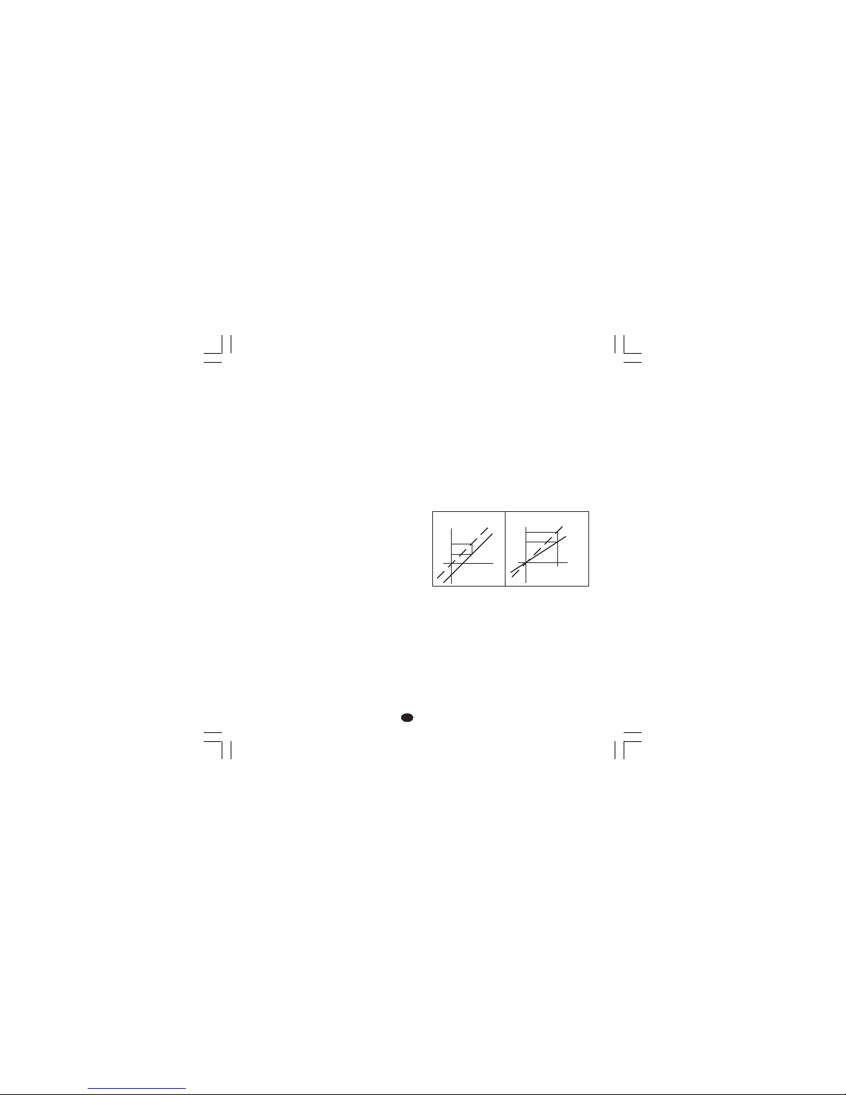
11
DD
DD
D
P10 = Alarm 2P10 = Alarm 2
P10 = Alarm 2P10 = Alarm 2
P10 = Alarm 2
0 = nicht vorgesehen
1 = Vollbereichsalarm.
2 = Bandalarm
3 = Abweichungsalarm.
Der Ausgang des Alarms 2 ist mit dem Ausgang
der Funktion “Heizleiterbruch” (HBD) in OR
geschaltet (siehe Parameter P16).
P11 = Wirkungsweise Alarm 2 und RücksetzenP11 = Wirkungsweise Alarm 2 und Rücksetzen
P11 = Wirkungsweise Alarm 2 und RücksetzenP11 = Wirkungsweise Alarm 2 und Rücksetzen
P11 = Wirkungsweise Alarm 2 und Rücksetzen
des Heizleiterbruch-Alarmsdes Heizleiterbruch-Alarms
des Heizleiterbruch-Alarmsdes Heizleiterbruch-Alarms
des Heizleiterbruch-Alarms
Dieser Parameter wird nur wenn P10 = 0 oder
P16 = OFF ist, NICHT angezeigt.
H.A. = Maximumalarm (außerhalb des Bandes)
mit automatischer Rücksetzung
L.A. = Minimumalarm (innerhalb des Bandes) mit
automatischer Rücksetzung
H.L. = Maximumalarm (außerhalb des Bandes)
mit manuellem Rücksetzen
L.L. = Minimumalarm (innerhalb des Bandes) mit
manuellem Rücksetzen
ANMERKUNG:ANMERKUNG:
ANMERKUNG:ANMERKUNG:
ANMERKUNG: Der Heizleiterbruch-Alarm ist
immer ein Minimumalarm, nimmt aber die
für den Alarm 2 eingestellte Art der
Rücksetzung an.
P12 = Unterdrückung des Alarms 2P12 = Unterdrückung des Alarms 2
P12 = Unterdrückung des Alarms 2P12 = Unterdrückung des Alarms 2
P12 = Unterdrückung des Alarms 2
Nur verfügbar, wenn P10 nicht 0 ist.
OF F = Alarmunterdrückung ausgeschaltet.
ON = Alarmunterdrückung eingeschaltet.
Weitere Angaben siehe Parameter P9.
P13 = Art der Meßwertkorrektur (OFFSET)P13 = Art der Meßwertkorrektur (OFFSET)
P13 = Art der Meßwertkorrektur (OFFSET)P13 = Art der Meßwertkorrektur (OFFSET)
P13 = Art der Meßwertkorrektur (OFFSET)
P13 = 0 konstanter OFFSET (P14) im
gesamten Meßbereich.
P13 ist nicht 0 P13 zeigt den Punkt an, an
dem der mit dem Parameter
P14 eingestellte Offset- Wert
angewandt wird.
ANMERKUNG:ANMERKUNG:
ANMERKUNG:ANMERKUNG:
ANMERKUNG: Die Parameter P13 und P14
ändern die Grenzen des Meß-oder
Anzeigebereichs des Geräts NICHT; deshalb
erfolgt bei Überschreitung einer dieser Grenzen
eine Bereichsüberschreitungsanzeige (Overrange
oder Underrange).
P14 = OFFSET-WertP14 = OFFSET-Wert
P14 = OFFSET-WertP14 = OFFSET-Wert
P14 = OFFSET-Wert
Wenn P13 = 0, kann P14 in physikalischen
Einheiten zwischen -20% und +20%
des Eingangsbereichs (P1)
programmiert werden.
Wenn P13 nicht 0 ist, kann P14 in physikalischen
Einheiten zwischen -20% und +20%
des Werts von P13 programmiert
werden.
ANMERKUNG: ANMERKUNG:
ANMERKUNG: ANMERKUNG:
ANMERKUNG: Der Wert des Parameters P14
kann nicht unter -199 Einheiten liegen.
P15 = Schaltschwelle der “Soft-Start”-P15 = Schaltschwelle der “Soft-Start”-
P15 = Schaltschwelle der “Soft-Start”-P15 = Schaltschwelle der “Soft-Start”-
P15 = Schaltschwelle der “Soft-Start”-
Funktion (weicher Start).Funktion (weicher Start).
Funktion (weicher Start).Funktion (weicher Start).
Funktion (weicher Start).
Schaltschwelle, in physikalischen Einheiten, zur
automatischen Aktivierung der Soft Start -Funktion
(zeitabhängige Ausgangsleistungsbegrenzung).
Wenn bei der Einschaltung des Geräts der Meßwert
unter der eingestellten Schaltschwelle liegt, schaltet
das Gerät automatisch die Begrenzung der
Ausgangsleistung ein und hält sie eine
vorprogrammierte Zeit lang aufrecht (siehe Parameter
“tOL” im Abschnitt “BETRIEBSPARAMETER).
Wenn bei der Einschaltung der Parameter “tOL”
gleich unendlich ist (Begrenzung immer eingeschaltet)
berücksichtigt das Gerät diesen Parameter nicht.
P13 = 0
Anzeige
modifizierte
Kurve
Eingang
P14
reale
Kurve
P13
Anzeige
P14
Eingang
reale
Kurve
modifizierte
Kurve
TMS-3-01.pmd 16/02/2005, 14.2211
Page 63

12
DD
DD
D
P16 = Messung der Stromaufnahme der überP16 = Messung der Stromaufnahme der über
P16 = Messung der Stromaufnahme der überP16 = Messung der Stromaufnahme der über
P16 = Messung der Stromaufnahme der über
den Hauptausgangden Hauptausgang
den Hauptausgangden Hauptausgang
den Hauptausgang
gesteuerten Last gesteuerten Last
gesteuerten Last gesteuerten Last
gesteuerten Last
(Heizleiterbruch)(Heizleiterbruch)
(Heizleiterbruch)(Heizleiterbruch)
(Heizleiterbruch)
OF F = Strommessung nicht aktiviert
n.O. = Strommessung während der ON-Periode
eingeschaltet (Status 1 für SSR oder Last
über den NO-Kontakt vorgesteuert).
n.C. = Strommessung während der OFF-Periode
eingeschaltet (Status 0 für SSR oder Last
über den NC-Kontakt vorgesteuert).
P17 = Endwert StromwandlerP17 = Endwert Stromwandler
P17 = Endwert StromwandlerP17 = Endwert Stromwandler
P17 = Endwert Stromwandler
Nur verfügbar, wenn P16 nicht OFF ist.
10 = 10 A Endwert (Auflösung 0.1 A)
25 = 25 A Endwert (Auflösung 1 A)
50 = 50 A Endwert (Auflösung1 A)
100 = 100 A Endwert (Auflösung 1 A)
P18 =P18 =
P18 =P18 =
P18 =
Zugriffsschlüssel für dieZugriffsschlüssel für die
Zugriffsschlüssel für dieZugriffsschlüssel für die
Zugriffsschlüssel für die
RegelparameterRegelparameter
RegelparameterRegelparameter
Regelparameter
0 = Parameter immer zugänglich.
1 = Der Sollwert kann geändert werden; alle
anderen Parameter sind geschützt.
Von 2 bis 499 = SP (Sollwert) kann immer
geändert werden, während
dieser Nummerncode die
Änderung der restlichen
Betriebsparameter freigibt
oder sperrt.
Von 500 bis 999 = SP, A1 und A2 können immer
geändert werden, während
dieser Nummerncode die
Änderung der restlichen
Betriebsparameter freigibt
oder sperrt.
ANMERKUNG:ANMERKUNG:
ANMERKUNG:ANMERKUNG:
ANMERKUNG: Nachdem die Taste FUNC
gedrückt wurde, kann der Wert dieses Parameters
NICHT mehr angezeigt werden. Falls der alte
Sicherungscode nicht bekannt ist, einen neuen
einstellen.
Die Standardkonfigurationsprozedur ist
abgeschlossen und das Gerät zeigt auf beiden
Displays
" -.-.-." an.
Falls keine weiteren Einstellungen vorgenommen
werden sollen, FUNC drücken, wodurch das Gerät
an den Anfang des Konfigurationsverfahrens
zurückkehrt.
Falls eine vollständige Konfiguration durchgeführt
werden soll, die Tasten
oder drücken und auf
dem oberen Display den Wert 217 einstellen.
Die Taste FUNC drücken; das Gerät beginnt das
Hilfskonfigurationsverfahren, wobei es die
folgenden zusätzlichen Parameter anzeigt:
P19 - Verhalten des HauptausgangsP19 - Verhalten des Hauptausgangs
P19 - Verhalten des HauptausgangsP19 - Verhalten des Hauptausgangs
P19 - Verhalten des Hauptausgangs
Nur verfügbar, wenn P4 = H.
r = indirekt (Heizen)
d = direkt (Kühlen)
Anmerkung: Wenn P4 = HC, wird dieser
Parameter auf “r” modifiziert.
P21 -P21 -
P21 -P21 -
P21 -
Verhalten des Relais in Bezug auf denVerhalten des Relais in Bezug auf den
Verhalten des Relais in Bezug auf denVerhalten des Relais in Bezug auf den
Verhalten des Relais in Bezug auf den
Alarm 1Alarm 1
Alarm 1Alarm 1
Alarm 1
Dieser Parameter wird nur angezeigt, wenn P7 nicht
0 und P4 gleich H ist.
r = indirekt (Relais bei Alarm abgefallen).
d = direkt (Relais bei Alarm angezogen).
t
Eingang
t
Ausgang
t
Eingang
t
Ausgang
Indirekt Direkt
TMS-3-01.pmd 16/02/2005, 14.2212
Page 64

13
DD
DD
D
P22 - Verhalten des Relais in Bezug auf denP22 - Verhalten des Relais in Bezug auf den
P22 - Verhalten des Relais in Bezug auf denP22 - Verhalten des Relais in Bezug auf den
P22 - Verhalten des Relais in Bezug auf den
Alarm 2Alarm 2
Alarm 2Alarm 2
Alarm 2
Dieser Parameter wird nicht angezeigt, wenn
P10 = 0 und P16 = OFF ist.
r = indirekt (Relais bei Alarm abgefallen)
d = direkt (Relais bei Alarm angezogen).
P23 -P23 -
P23 -P23 -
P23 -
Automatische Änderung der “relativenAutomatische Änderung der “relativen
Automatische Änderung der “relativenAutomatische Änderung der “relativen
Automatische Änderung der “relativen
Kühlverstärkung”.Kühlverstärkung”.
Kühlverstärkung”.Kühlverstärkung”.
Kühlverstärkung”.
Nur verfügbar, wenn P4 = HC.
OFF = Die SMART-Funktion ändert den Wert des
Parameters “relative Kühlverstärkung”
NICHTNICHT
NICHTNICHT
NICHT.
ON = Die SMART-Funktion ändert den Wert des
Parameters “relative Kühlverstärkung”.
P24 -P24 -
P24 -P24 -
P24 -
Höchstgeschwindigkeit der Änderung desHöchstgeschwindigkeit der Änderung des
Höchstgeschwindigkeit der Änderung desHöchstgeschwindigkeit der Änderung des
Höchstgeschwindigkeit der Änderung des
AusgangssignalsAusgangssignals
AusgangssignalsAusgangssignals
Ausgangssignals
Dieser Parameter ermöglicht die Einstellung der
Höchstgeschwindigkeit der Änderung des
Ausgangssignals.
P24 kann von 1 bis 10% des Ausgangsbereichs pro
Sekunde eingestellt werden.
Bei Werten über 10% schaltet das obere Display
sich aus und das Gerät führt keine Begrenzung der
Änderungsgeschwindigkeit durch.
P25 - Anzeige der verriegelten ParameterP25 - Anzeige der verriegelten Parameter
P25 - Anzeige der verriegelten ParameterP25 - Anzeige der verriegelten Parameter
P25 - Anzeige der verriegelten Parameter
Dieser Parameter wird nur angezeigt, wenn P18
nicht 0 ist.
OFF = Das Gerät zeigt die verriegelten Parameter
NICHT an.
ON = Alle Parameter können angezeigt
werden.
P26 - Aktivierung/Deaktivierung der SMART-P26 - Aktivierung/Deaktivierung der SMART-
P26 - Aktivierung/Deaktivierung der SMART-P26 - Aktivierung/Deaktivierung der SMART-
P26 - Aktivierung/Deaktivierung der SMART-
FunktionFunktion
FunktionFunktion
Funktion
0 = Die SMART-Funktion ist immer deaktiviert.
1 = Die Aktivierung bzw. Deaktivierung der
SMART-Funktion ist
NICHTNICHT
NICHTNICHT
NICHT verriegelt.
2 = Die Aktivierung bzw. Deaktivierung der
SMART-Funktion ist verriegelt.
P27 - Von der SMART-Funktion einstellbarerP27 - Von der SMART-Funktion einstellbarer
P27 - Von der SMART-Funktion einstellbarerP27 - Von der SMART-Funktion einstellbarer
P27 - Von der SMART-Funktion einstellbarer
max. Wert des Proportionalbandes.max. Wert des Proportionalbandes.
max. Wert des Proportionalbandes.max. Wert des Proportionalbandes.
max. Wert des Proportionalbandes.
Nur verfügbar, wenn P26 nicht 0 ist.
Dieser Parameter kann zwischen dem Wert von
P28 oder P29 und 99,9 programmiert werden.
P28 - Von der SMART-Funktion einstellbarerP28 - Von der SMART-Funktion einstellbarer
P28 - Von der SMART-Funktion einstellbarerP28 - Von der SMART-Funktion einstellbarer
P28 - Von der SMART-Funktion einstellbarer
min. Wert des Proportionalbandesmin. Wert des Proportionalbandes
min. Wert des Proportionalbandesmin. Wert des Proportionalbandes
min. Wert des Proportionalbandes
Nur verfügbar, wenn P26 nicht 0 und P4 = H.
Dieser Parameter kann zwischen 1,0% und dem
Wert von P27 programmiert werden.
P29 - Von der SMART-Funktion nur für dieP29 - Von der SMART-Funktion nur für die
P29 - Von der SMART-Funktion nur für dieP29 - Von der SMART-Funktion nur für die
P29 - Von der SMART-Funktion nur für die
Regelung Heizen/Kühlen einstellbarer min.Regelung Heizen/Kühlen einstellbarer min.
Regelung Heizen/Kühlen einstellbarer min.Regelung Heizen/Kühlen einstellbarer min.
Regelung Heizen/Kühlen einstellbarer min.
Wert des ProportionalbandesWert des Proportionalbandes
Wert des ProportionalbandesWert des Proportionalbandes
Wert des Proportionalbandes
Nur verfügbar, wenn P26 nicht 0 und P4 = HC.
Dieser Parameter kann zwischen 1,5% und dem
Wert von P27 programmiert werden.
P30 - Mindestwert des von der SMART-P30 - Mindestwert des von der SMART-
P30 - Mindestwert des von der SMART-P30 - Mindestwert des von der SMART-
P30 - Mindestwert des von der SMARTFunktion einstellbaren Integralanteils.Funktion einstellbaren Integralanteils.
Funktion einstellbaren Integralanteils.Funktion einstellbaren Integralanteils.
Funktion einstellbaren Integralanteils.
Nur verfügbar, wenn P26 nicht 0 ist.
P30 ist von 00,1 [mm.s] bis 02,0 [mm.s]
programmierbar.
TMS-3-01.pmd 16/02/2005, 14.2213
Page 65

14
DD
DD
D
P31 - Erweiterung des Anti-reset-wind upP31 - Erweiterung des Anti-reset-wind up
P31 - Erweiterung des Anti-reset-wind upP31 - Erweiterung des Anti-reset-wind up
P31 - Erweiterung des Anti-reset-wind up
Bereich: Von -30 bis +30% des Proportionalbandes.
ANMERKUNG:ANMERKUNG:
ANMERKUNG:ANMERKUNG:
ANMERKUNG: Ein positiver Wert erhöht die
max. Grenze der Funktion (über den Sollwert),
während ein negativer Wert die min. Grenze der
Funktion senkt (unter den Sollwert).
Das Hilfskonfigurationsverfahren ist
abgeschlossen und das Gerät zeigt auf dem
oberen Display “CnF” an.
BETRIEBSMODUSBETRIEBSMODUS
BETRIEBSMODUSBETRIEBSMODUS
BETRIEBSMODUS
1) Das Gerät aus dem Gehäuse ziehen.
2) Den Hakenschalter V2 (siehe Abb.13)
schließen.
3) Das Gerät in das Gehäuse zurückschieben.
4) Das Gerät mit Strom versorgen.
Das obere Display zeigt den Meßwert an,
während auf dem unteren Display der eingestellte
Sollwert erscheint (dieser Zustand wird als
“Normale Anzeigeart” definiert).
Anmerkung:Anmerkung:
Anmerkung:Anmerkung:
Anmerkung: Erfolgt eine Sollwertvorgabe
mittels Rampenfunktion Parameter
rP), könnte der Wert des
angezeigten Sollwerts vom
Betriebsollwert
abweichen.
Wenn die Funktion HBD (Heizleiterbruch)
konfiguriert und der Regelausgang aktiviert ist
und das Gerät auf normale Anzeigeart gestellt ist,
kann durch Druck auf die Taste
auf dem
unteren Display der Wert (gefolgt von dem
Symbol A) des Stromverbrauchs der über den
Ausang 1 vorgesteuerten Last angezeigt werden.
ANMERKUNG:ANMERKUNG:
ANMERKUNG:ANMERKUNG:
ANMERKUNG: Diese Anzeige ist KEINER
zeitlichen Begrenzung (Time out) unterworfen.
Um zur normalen Anzeigeart zurückzukehren,
erneut die Taste
drücken.
TMS-3-01.pmd 16/02/2005, 14.2214
Page 66

15
DD
DD
D
SPERRE DES AUSGANGSSIGNALSSPERRE DES AUSGANGSSIGNALS
SPERRE DES AUSGANGSSIGNALSSPERRE DES AUSGANGSSIGNALS
SPERRE DES AUSGANGSSIGNALS
Das Modell TMS ermöglicht die manuelle Sperre
des Ausgangssignals, um die Regelaktion zu
unterbrechen (in diesem Fall funktioniert das
Instrument als einfaches Anzeigegerät).
Zur Sperre des Ausgangssignals wie folgt
vorgehen:
1) Die Taste drücken und niedergedrückt
halten.
2) Die Taste FUNC drücken.
3) Beide Tasten länger als 3 Sekunden lang
niedergedrückt halten.
Auf dem oberen Display erscheint die Meldung
“OFF”, womit die Sperre des Regelausgangs
angezeigt wird.
Soll die automatische Regelung wieder aktiviert
werden, die oben angeführten Schritte
wiederholen: Das Gerät kehrt automatisch zur
“Normalen Anzeigeart” zurück.
ANMERKUNGEN:ANMERKUNGEN:
ANMERKUNGEN:ANMERKUNGEN:
ANMERKUNGEN:
1) Das Gerät speichert den Zustand der Sperre des
Ausgangs.
2) Wenn das Ausgangssignal gesperrt wird, während
die SMART-Funktion den ersten Teil des
Selbstoptimierungs-Algorithmus durchführt (die
LED SMRT blinkt), unterbricht das Gerät die
Ausführung des Algorithmus und bei der Rückkehr
zur normalen Regelfunktion ist die SMARTFunktion ausgeschaltet.
Wenn das Ausgangssignal gesperrt wird, während
die SMART-Funktion den Teil der ständigen
Selbstoptimierung des Algorithmus durchführt
(die LED SMRT leuchtet stetig), unterbricht das
Gerät vorübergehend die Ausführung des
Algorithmus; sobald das Gerät zum normalen
Regelverhalten zurückkehrt, ist die SMARTFunktion erneut aktiviert.
SMART-ALGORITHMUSSMART-ALGORITHMUS
SMART-ALGORITHMUSSMART-ALGORITHMUS
SMART-ALGORITHMUS
Der Algorithmus SMART ist ein neuer Algorithmus
zur automatischen Selbstoptimierung. Das Gerät
verwendet die SMART-Funktion zur
automatischen Berechnung und Einstellung der
Regelparameter. Der SMART-Algorithmus kann
immer eingeschaltet sein, um eine ständige
Selbstoptimierung der Parameter in Funktion der
eventuellen Änderungen der Bedingungen der
Anlage zu erhalten. Zur Aktivierung dieser
Funktion, die Taste SMRT länger als 1,5 s
niederdrücken, wenn das Gerät auf “Normale
Anzeigeart” eingestellt ist. Die Kontrollampe SMRT
beginnt, in Funktion der Selbstoptimierungsphase,
zu blinken oder stetig zu leuchten. Zur
Deaktivierung der SMART-Funktion, einfach die
Taste SMRT drücken; die entsprechende Lampe
SMRT schaltet sich aus.
ANMERKUNGEN:ANMERKUNGEN:
ANMERKUNGEN:ANMERKUNGEN:
ANMERKUNGEN:
1) Wenn die SMART-Funktion aktiviert ist, wird die
relative Kühlverstärkung (wenn vorhanden) auf
den Bereich der folgenden Werte begrenzt:
Kühlmedium Bereich
Luft von 0,85 bis 1,00
Öl von 0,80 bos 0,90
Wasser von 0,30 bis 0,60
2) Die SMART-Funktion verwendet eine
Vorhalteaktion die einem Viertel der
Nachstellaktion entspricht.
3) Die von der SMART-Funktion einstellbaren
Grenzen des Proportionalbandes und der
Integralzeit können über die Parameter P27, P28,
P29 und P30 programmiert werden (siehe
Abschnitt 3).
4) Die Aktivierung/Deaktivierung der SMARTFunktion kann durch den Sicherungsschlüssel
geschützt werden (siehe Parameter P18).
5) Wenn die SMART-Funktion eingeschaltet ist,
können die Parameter Pb, ti und td nicht über die
Frontta statur geändert werden. Für den Parameter
rC siehe P23.
TMS-3-01.pmd 16/02/2005, 14.2215
Page 67

16
DD
DD
D
DIREKTE ÄNDERUNG DES SOLLWERTSDIREKTE ÄNDERUNG DES SOLLWERTS
DIREKTE ÄNDERUNG DES SOLLWERTSDIREKTE ÄNDERUNG DES SOLLWERTS
DIREKTE ÄNDERUNG DES SOLLWERTS
Bei diesem Gerät kann der Sollwert ohne
Verwendung der Taste FUNC geändert werden.
Wenn der eingestellte Sollwert rasch geändert
werden soll, wie folgt vorgehen:
1) Länger als 3 Sekunden lang die Taste oder
drücken; Der auf dem unteren Display angezeigte
Sollwert beginnt sich zu ändern.
2) Mit den Tasten
und den gewünschten
Sollwert einstellen.
3) Sobald der gewünschte Wert erreicht ist,
mindestens 3 Sekunden lang KEINE Taste
drücken. Der neue Sollwert wird 3 Sekunden
nach dem letzten Tastendruck wirksam.
Falls während dieses Verfahrens die Änderung
des Sollwers unterbrochen werden soll, die Taste
FUNC drücken; das Gerät kehrt automatisch zur
normalen Anzeigeart zurück, ohne den neuen
Wert zu speichern.
ÜBERPRÜFUNG DER KONTROLLAMPENÜBERPRÜFUNG DER KONTROLLAMPEN
ÜBERPRÜFUNG DER KONTROLLAMPENÜBERPRÜFUNG DER KONTROLLAMPEN
ÜBERPRÜFUNG DER KONTROLLAMPEN
(LAMP TEST)(LAMP TEST)
(LAMP TEST)(LAMP TEST)
(LAMP TEST)
Zur Überprüfung der einwandfreien
Funktionstüchtigkeit der Anzeige, die Tasten
und FUNC drücken. Das Gerät schaltet alle
LED’S der Anzeige mit einem festen Zyklus gleich
50% ein (dieser Status wird LAMP TEST
genannt).
Für den LAMP TEST ist kein Time out
festgesetzt. Um zur “Normalen Anzeigeart”
zurückzukehren, erneut die Tasten und FUNC
drücken.
Während des LAMP TESTS ist das Gerät normal
betriebsbereit, aber über die Fronttastatur kann
nur der Test deaktiviert werden.
HEIZLEITERBRUCH-ALARMHEIZLEITERBRUCH-ALARM
HEIZLEITERBRUCH-ALARMHEIZLEITERBRUCH-ALARM
HEIZLEITERBRUCH-ALARM
(Alarm bei Funktionsstörung der über den(Alarm bei Funktionsstörung der über den
(Alarm bei Funktionsstörung der über den(Alarm bei Funktionsstörung der über den
(Alarm bei Funktionsstörung der über den
Hauptausgang gesteuerten Last)Hauptausgang gesteuerten Last)
Hauptausgang gesteuerten Last)Hauptausgang gesteuerten Last)
Hauptausgang gesteuerten Last)
Diese Funktion ermöglicht es, die Stromaufnahme
der über den Heizausgang vorgesteueren Last
ständig zu kontrollieren und einen Alarm zu
erzeugen, falls ein Stromverbrauch erfaßt wird,
der unter der eingestellten Schaltschwelle liegt.
Zur Anzeige der Stromaufnahme dieser Last, die
Taste drücken, wenn das Gerät auf “Normale
Anzeigeart” eingestellt ist.
Das obere Display zeigt weiterhin den Istwert an,
während das untere Display den abgenommenen
Strom anzeigt (in Ampere), gefolgt von der
physikalischen Einheit (A).
Um zur “Normalen Anzeigeart” zurückzukehren,
erneut die Taste drücken.
Falls das Gerät einen Alarmzustand erfaßt,
beginnt die LED AL2/HB zu blinken und das dem
Ausgang 3 entsprechende Relais spricht an.
TMS-3-01.pmd 16/02/2005, 14.2216
Page 68

17
DD
DD
D
BETRIEBSPARAMETERBETRIEBSPARAMETER
BETRIEBSPARAMETERBETRIEBSPARAMETER
BETRIEBSPARAMETER
Änderung der BetriebsparameterÄnderung der Betriebsparameter
Änderung der BetriebsparameterÄnderung der Betriebsparameter
Änderung der Betriebsparameter
Die Taste FUNC drücken: Das untere Display
zeigt den Code an, während auf dem oberen
Display der Wert des angewählten Parameters
erscheint.
Mit den Tasten und kann der gewünschte
Wert oder Status eingestellt werden.
Durch Druck auf die Taste FUNC speichert das
Gerät den neuen Wert (oder neuen Status) und
geht zur Anzeige des folgenden Parameters über.
Ein kurzer Druck auf die Taste SMRT ermöglicht
es, zum vorangegangenen Parameter zurückzukehren, ohne den neuen Wert des aktuellen
Parameters zu speichern.
Einige der folgenden Parameter könnten, in
Funktion der Konfiguration des Geräts, nicht
angezeigt werden.
ANMERKUNGENANMERKUNGEN
ANMERKUNGENANMERKUNGEN
ANMERKUNGEN:
1) Wenn während der Änderung oder
Anzeige der Parameter länger als 10
Sekunden keine Taste gedrückt wird,
kehrt das Gerät zur “Normalen
Anzeigeart” zurück, ohne den neuen
Wert des letzten Parameters zu
speichern.
2) Das Gerät zeigt nicht alle Parameter
an, sondern nur jene, die in Funktion:
a) der Konfiguration des Geräts
b) der Einstellung des Parameters P25
c) der Einstellung des
Proportionalbandes
signifikant sind.
Param. Beschreibung
SP
Haupt-SollwertHaupt-Sollwert
Haupt-SollwertHaupt-Sollwert
Haupt-Sollwert (in physikalischen Einheiten)
Bereich: von rL bis rH.
n.rS
Manuelles Rücksetzen der AlarmeManuelles Rücksetzen der Alarme
Manuelles Rücksetzen der AlarmeManuelles Rücksetzen der Alarme
Manuelles Rücksetzen der Alarme
Dieser Parameter wird angezeigt, wenn
zumindest ein Alarm mit manuellem
Rücksetzen programmiert wurde.
ON einstellen und FUNC drücken, um die
Alarme zurückzusetzen.
nnn
Sicherungsschlüssel für die VerriegelungSicherungsschlüssel für die Verriegelung
Sicherungsschlüssel für die VerriegelungSicherungsschlüssel für die Verriegelung
Sicherungsschlüssel für die Verriegelung
der Parameterder Parameter
der Parameterder Parameter
der Parameter
Wird nicht angezeigt, wenn P18= 0 oder 1.
Das Gerät zeigt bei Einschaltung den Status
an:
ON = Die Parameter sind verriegelt.
OFF= Die Parameter sind nicht verriegelt.
Falls die Verriegelung der Parameter
deaktiviert werden soll, einen Wert einstellen,
der dem P18 zugeordneten Wert gleich ist.
Wenn die Verriegelung wieder aktiviert werden
soll, einen Wert einstellen, der von dem P18
zugeordneten Wert abweicht.
A1
Schaltschwelle Alarm 1Schaltschwelle Alarm 1
Schaltschwelle Alarm 1Schaltschwelle Alarm 1
Schaltschwelle Alarm 1
A1 wird nur angezeigt, wenn der Alarm
konfiguriert wurde.
Bereiche:
- Innerhalb des Eingangsbereiches für
Vollbereichsalarme.
- Von 0 bis 500 Einheiten für Bandalarme.
- Von -199 bis 500 Einheiten für Abweichungsalarme.
A2
Schaltschwelle Alarm 2Schaltschwelle Alarm 2
Schaltschwelle Alarm 2Schaltschwelle Alarm 2
Schaltschwelle Alarm 2
Für weitere Angaben siehe Parameter A1.
H1
Hysterese Alarm 1Hysterese Alarm 1
Hysterese Alarm 1Hysterese Alarm 1
Hysterese Alarm 1
Dieser Parameter wird nur angezeigt, wenn
der entsprechende Alarm konfiguriert wurde.
Bereich: Von 0,1% bis 10,0% des
Eingangsbereiches oder 1 LSD.
TMS-3-01.pmd 16/02/2005, 14.2217
Page 69

18
DD
DD
D
Anmerkung:Anmerkung:
Anmerkung:Anmerkung:
Anmerkung: Falls die Hysterese eines
Bandalarms breiter als das Band des Alarms
selbst ist, verwendet das Gerät einen
Hysteresewert der dem programmierten
Bandwert minus einem Digit entspricht.
H2
Hysterese Alarm 2Hysterese Alarm 2
Hysterese Alarm 2Hysterese Alarm 2
Hysterese Alarm 2
Für weitere Angaben siehe Parameter H1.
Pb
ProportionalbandProportionalband
ProportionalbandProportionalband
Proportionalband
Bereich: Von 1,0% bis 99,9% der Breite des
Eingangsbereichs bei einem Regelausgang.
Von 1,5% bis 99,9% der Breite des
Eingangsbereichs bei zwei Regelausgängen
Wenn Pb = 0, wird das Regelverhalten ON/
OFF; die Parameter ti, td, IP, C, C2, rC, OLP,
OLH und tOL werden nicht angezeigt, und die
SMART-Funktion kann nicht aktiviert werden.
Anmerkung:Anmerkung:
Anmerkung:Anmerkung:
Anmerkung: Falls die Hysterese des
Bandalarms breiter als das Band des Alarms
selbst ist, verwendet das Gerät einen
Hysteresewert, der dem programmierten
Bandwert minus einem Digit entspricht.
HS
Hysterese für die ON/OFF-RegelungHysterese für die ON/OFF-Regelung
Hysterese für die ON/OFF-RegelungHysterese für die ON/OFF-Regelung
Hysterese für die ON/OFF-Regelung
HS ist nur verfügbar, wenn Pb = 0.
Bereich: Von 0,1% bis 10,0% der Breite des
Eingangsbereichs.
ti
Nachstellzeit (Integralzeit)Nachstellzeit (Integralzeit)
Nachstellzeit (Integralzeit)Nachstellzeit (Integralzeit)
Nachstellzeit (Integralzeit)
“ti” wird nicht angezeigt, wenn Pb = 0
(ON/OFF-Regelverhalten).
Bereich: Von 00,1 bis 20,0 mm.ss.Bei höheren
Werten verdunkelt sich das Display und die
Nachstellzeit wird ausgeschlossen.
Anmerkung:Anmerkung:
Anmerkung:Anmerkung:
Anmerkung: Wenn die SMART-Funktion
verwendet wird, wird der Mindestwert der
Integralzeit durch den Parameter P30
festgelegt.
td
Vorhaltezeit (Differentialzeit)Vorhaltezeit (Differentialzeit)
Vorhaltezeit (Differentialzeit)Vorhaltezeit (Differentialzeit)
Vorhaltezeit (Differentialzeit)
“td” wird nicht angezeigt, wenn Pb = 0
(ON/OFF-Regelverhalten).
Bereich: Von 0,01 bis 9,59 m.ss. Wird der
Wert 0 eingestellt, ist die Vorhaltezeit
ausgeschlossen.
Anmerkung:Anmerkung:
Anmerkung:Anmerkung:
Anmerkung: Wird die SMART-Funktion
verwendet, entspricht der Wert des
Parameters “td” einem Viertel des dem
Parameter “ti” zugeordneten Werts.
IP
Anfangsladen der Nachstellzeit.Anfangsladen der Nachstellzeit.
Anfangsladen der Nachstellzeit.Anfangsladen der Nachstellzeit.
Anfangsladen der Nachstellzeit.
“IP” wird nicht angezeigt, wenn Pb= 0.
(ON/OFF-Aktion) Bereiche:
- Von 0 bis 100%, wenn P4 = H
- Von -100 bis 100%, wenn P4 = HC
C
Zykluszeit Ausgang 1Zykluszeit Ausgang 1
Zykluszeit Ausgang 1Zykluszeit Ausgang 1
Zykluszeit Ausgang 1
C ist nur verfügbar, wenn Pb nicht 0 ist.
Bereich: Von 1 bis 200 s.
C2
Zykluszeit Ausgang 2Zykluszeit Ausgang 2
Zykluszeit Ausgang 2Zykluszeit Ausgang 2
Zykluszeit Ausgang 2
C2 ist nur verfügbar, wenn P4 = “HC” und Pb
nicht 0 ist.
Bereich: Von 1 bis 200 s.
rC
Relative KühlverstärkungRelative Kühlverstärkung
Relative KühlverstärkungRelative Kühlverstärkung
Relative Kühlverstärkung
“rC” wird nicht angezeigt, wenn Pb = 0
(ON/OFF-Regelverhalten) oder wenn P4 = H.
Bereich: Von 0,20 bis 1,00.
Anmerkung:Anmerkung:
Anmerkung:Anmerkung:
Anmerkung: Wenn die SMART-Funktion
aktiviert ist, wird der Parameter “rC” in Funktion
des gewählten Kühlmediums begrenzt:
- von 0,85 bis 1,00 wenn P6 = Air
- von 0,80 bis 0,90 wenn P6 = OIL
- von 0,30 bis 0,60 wenn P6 = H2O
OLP
Überlagerung/Totband zwischen HeizenÜberlagerung/Totband zwischen Heizen
Überlagerung/Totband zwischen HeizenÜberlagerung/Totband zwischen Heizen
Überlagerung/Totband zwischen Heizen
und Kühlenund Kühlen
und Kühlenund Kühlen
und Kühlen
“OLP” wird nicht angezeigt, wenn Pb = 0
(ON/OFF-Regelverhalten) oder wenn P4 = H.
Ein negativer Wert zeigt ein Totband an, ein
positiver Wert eine Überlagerung.
Bereich: Von -20 bis 50.
rL
Untere Grenze des SollwertsUntere Grenze des Sollwerts
Untere Grenze des SollwertsUntere Grenze des Sollwerts
Untere Grenze des Sollwerts
Bereich: Vom Anfangswert (P2) bis rH.
Anmerkung:Anmerkung:
Anmerkung:Anmerkung:
Anmerkung: Bei einer Änderung von P2, wird
auch rL automatisch angeglichen.
TMS-3-01.pmd 16/02/2005, 14.2218
Page 70

19
DD
DD
D
rH
Obere Grenze des SollwertsObere Grenze des Sollwerts
Obere Grenze des SollwertsObere Grenze des Sollwerts
Obere Grenze des Sollwerts
Bereich: Von rL bis zum Endwert (P3).
Anmerkung:Anmerkung:
Anmerkung:Anmerkung:
Anmerkung: Bei einer Änderung von P3, wird
auch rH automatisch angegleichen.
rP
An die Änderungen des Sollwerts angelegteAn die Änderungen des Sollwerts angelegte
An die Änderungen des Sollwerts angelegteAn die Änderungen des Sollwerts angelegte
An die Änderungen des Sollwerts angelegte
RampeRampe
RampeRampe
Rampe
Bereich: von 1 bis 100 Digits/Minute. Über
diesem Wert, zeigt das Display “Inf” an und die
Umschaltung erfolgt in einem Sprung.
OLH
Max.Grenze des RegelausgangsMax.Grenze des Regelausgangs
Max.Grenze des RegelausgangsMax.Grenze des Regelausgangs
Max.Grenze des Regelausgangs
“OLH” wird nicht angezeigt, wenn Pb = 0
(ON/OFF-Aktion).
Bereich:
- Von 0 bis 100%, wenn P4 = H
- Von -100 bis 100%, wenn P4 = HC
tOL
Dauer der AusgangsleistungsbegrenzungDauer der Ausgangsleistungsbegrenzung
Dauer der AusgangsleistungsbegrenzungDauer der Ausgangsleistungsbegrenzung
Dauer der Ausgangsleistungsbegrenzung
“tOL” wird nicht angezeigt, wenn Pb = 0
(ON/OFF-Aktion).
Bereich: Von 1 bis 100 Min. Bei höheren
Werten zeigt das Display “Inf” an und die
Begrenzung ist immer aktiviert.
Anmerkung:Anmerkung:
Anmerkung:Anmerkung:
Anmerkung: Der Parameter tOL kann
jederzeit geändert werden, aber der neue
Wert wird erst bei der folgenden Einschaltung
des Geräts wirksam.
Hbd
Schaltschwelle für die Anzeige desSchaltschwelle für die Anzeige des
Schaltschwelle für die Anzeige desSchaltschwelle für die Anzeige des
Schaltschwelle für die Anzeige des
Stromverbrauchs der über denStromverbrauchs der über den
Stromverbrauchs der über denStromverbrauchs der über den
Stromverbrauchs der über den
Heizausgang vorgesteuerten Last.Heizausgang vorgesteuerten Last.
Heizausgang vorgesteuerten Last.Heizausgang vorgesteuerten Last.
Heizausgang vorgesteuerten Last.
Dieser Parameter wird nur angezeigt, wenn
P16 nicht OFF ist.
Bereich: Innerhalb des Meßbreichs des
Stromwandlers (siehe Parameter P17).
FEHLERMELDUNGENFEHLERMELDUNGEN
FEHLERMELDUNGENFEHLERMELDUNGEN
FEHLERMELDUNGEN
ANZEIGE VON ÜBER-BZW.ANZEIGE VON ÜBER-BZW.
ANZEIGE VON ÜBER-BZW.ANZEIGE VON ÜBER-BZW.
ANZEIGE VON ÜBER-BZW.
UNTERSCHREITUNGEN DESUNTERSCHREITUNGEN DES
UNTERSCHREITUNGEN DESUNTERSCHREITUNGEN DES
UNTERSCHREITUNGEN DES
MESSBEREICHSMESSBEREICHS
MESSBEREICHSMESSBEREICHS
MESSBEREICHS
Das Gerät zeigt die Erfassung einer
Meßbereichsüberschreitung (OVERRANGE) auf
dem oberen Display mit dem folgenden
graphischen Zeichen an:
Bei Unterschreitung des Meßbereichs
(UNDERRANGE) erscheint hingegen die folgende
graphische Anzeige
Der Bruch des Fühlers wird folgendermaßen
angezeigt:
-Thermoelement-/mV-Eingang: OVERRRANGE
oder UNDERRANGE durch
Positionierung des
Kodiersteckers wählbar (siehe
Abb. 12).
-Widerstandsthermometer-Eingang: OVERRANGE
Für den Widerstandsthermometer-Eingang
signalisiert das Instrument eine OVERRANGEBedingung, wenn der Eingangswiderstand unter
15 Ohm liegt (Erfassung des Kurzschlusses des
Fühlers).
TMS-3-01.pmd 16/02/2005, 14.2219
Page 71

20
DD
DD
D
ANMERKUNG:ANMERKUNG:
ANMERKUNG:ANMERKUNG:
ANMERKUNG:
- Wenn das Instrument für die Verwendung eines
einzigen Regelausgangs programmmiert wurde
und eine OVERRANGE- Bedingung erfaßt hat,
wird der Ausgang 1 auf 0 modifiziert (durch
umgekehrte Aktion), oder auf 100% (durch
direkte Aktion).
- Wenn das Instrument für die Verwendung von
zwei Regelausgängen programmmiert wurde
und eine OVERRANGE- Bedingung erfaßt hat,
wird der Ausgang 1auf 0, und der Ausgang 2 auf
100% modifiziert.
- Wenn das Instrument für die Verwendung einen
einzigen Regelausgang programmmiert wurde
und eine UNDERRANGE - Bedingung erfaßt
hat, wird der Ausgang 1 auf 100% modifiziert
(durch umgekehrte Aktion), oder auf 0 (durch
direkte Aktion).
- Wenn das Instrument für die Verwendung von
zwei Regelausgängen programmmiert wurde
und eine UNDERRANGE- Bedingung erfaßt hat,
wird der Ausgang 1 auf 100%, und der Ausgang
2 auf 0 modifiziert.
FEHLERMELDUNGENFEHLERMELDUNGEN
FEHLERMELDUNGENFEHLERMELDUNGEN
FEHLERMELDUNGEN
Das Gerät ist mit einigen SelbstdiagnoseAlgorithmen versehen.
Falls diese Algorithmen eine Störung erfassen,
erscheint auf dem unteren Display die Schrift “Err”,
während das obere Display die Kennzahl des
erfaßten Fehlers anzeigt.
VERZEICHNIS DER MÖGLICHEN FEHLERVERZEICHNIS DER MÖGLICHEN FEHLER
VERZEICHNIS DER MÖGLICHEN FEHLERVERZEICHNIS DER MÖGLICHEN FEHLER
VERZEICHNIS DER MÖGLICHEN FEHLER
100 Schreibfehler im EEPROM-Speicher.
150 Allgemeiner Fehler in der CPU.
200 Einschreibeversuch in geschützte Speicher.
201-2xx Fehler der Konfiguration der Parameter.
Die beiden letzten Ziffern zeigen die Nummer
des falschen Parameters an.
301 Fehler bei der Eichung für den RTD Eingang.
305 Fehler bei der Eichung für den TC Eingang.
307 Fehler bei der Eichung der Vergleichsstelle.
310 Fehler bei der Eichung für den
Stromwandler-Eingang.
400 Fehler in den Regelparametern.
500 Fehler während des automatischen
Nullabgleichs.
502 Fehler während der Messung der
Vergleichsstelle.
510 Allgemeiner Fehler während der Eichung.
ANMERKUNGEN:ANMERKUNGEN:
ANMERKUNGEN:ANMERKUNGEN:
ANMERKUNGEN:
1) Wenn das Instrument einen Fehler
in den Konfigurationsparametern
erfaßt, genügt es, die Konfiguration
des entsprechenden Parameters zu
wiederholen.
2) Wird der Fehler 400 angezeigt,
gleichzeitig die Tasten
und
drücken und die vordefinierten
Parameter laden; anschließend die
Einstellung der Regelparameter
wiederholen.
3) Bei allen anderen Fehlermeldungen
den Lieferanten informieren.
TMS-3-01.pmd 16/02/2005, 14.2220
Page 72
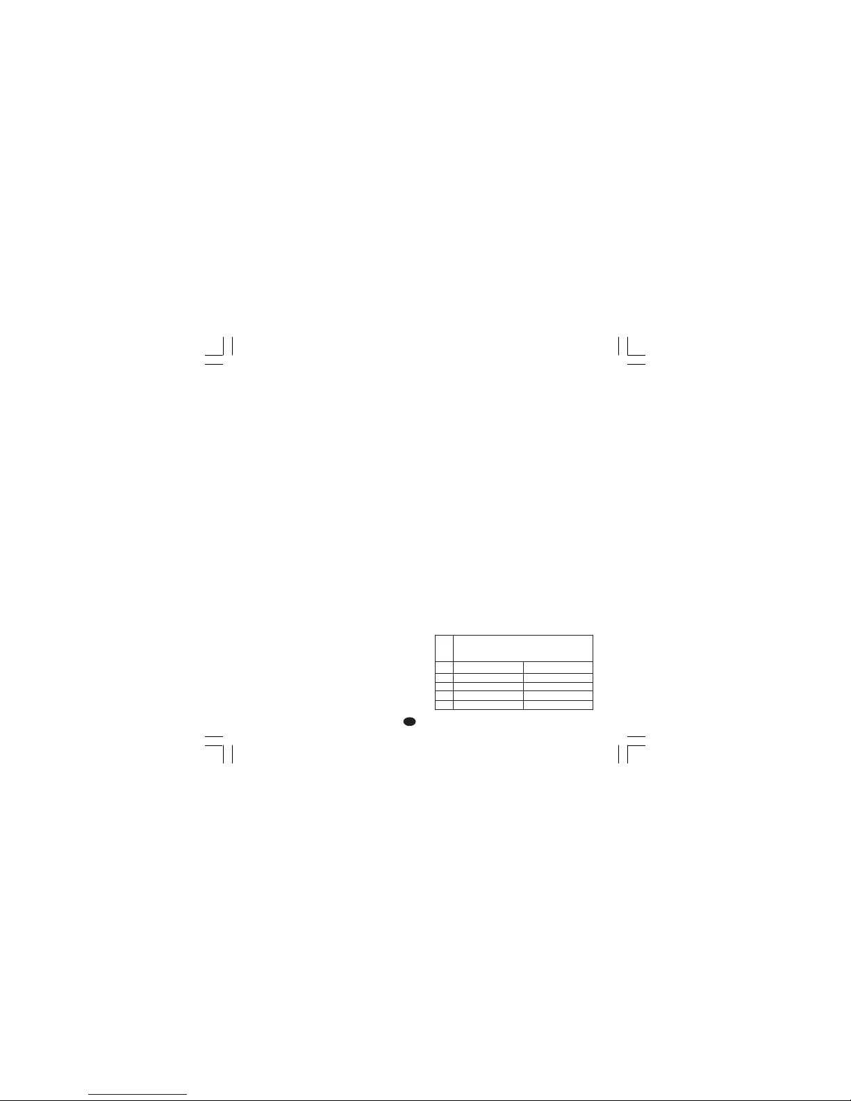
21
DD
DD
D
TECHNISCHE MERKMALETECHNISCHE MERKMALE
TECHNISCHE MERKMALETECHNISCHE MERKMALE
TECHNISCHE MERKMALE
TECHNISCHE SPEZIFIKATIONENTECHNISCHE SPEZIFIKATIONEN
TECHNISCHE SPEZIFIKATIONENTECHNISCHE SPEZIFIKATIONEN
TECHNISCHE SPEZIFIKATIONEN
Gehäuse:Gehäuse:
Gehäuse:Gehäuse:
Gehäuse: Schwarzes PC-ABS; Grad der
Selbstlöschung: V-0 gemäß UL 94.
Frontschutz:Frontschutz:
Frontschutz:Frontschutz:
Frontschutz: Entwickelt und getestet zur
Gewährleistung der Schutzklasse IP 65 (*) und
NEMA 4X bei Verwendung in geschlossenen
Räumen.
(* Die Überprüfungen wurden gemäß den CEINormen 70-1 und NEMA 250-1991) durchgeführt.
Installation:Installation:
Installation:Installation:
Installation: Fronttafeleinbau.
Rückseitiger Anschlußblock:Rückseitiger Anschlußblock:
Rückseitiger Anschlußblock:Rückseitiger Anschlußblock:
Rückseitiger Anschlußblock: 21 Schraubanschlüsse (Schraube M3 für Kabel mit ∅ von 0,25
bis ∅ 2,5mm² oder von AWG 22 bis AWG 14), mit
Anschlußbildern und Sicherheitsabdeckungen.
Abmessungen:Abmessungen:
Abmessungen:Abmessungen:
Abmessungen: Gemäß DIN 43700 48 x 96 mm,
Tiefe 89 mm.
GewichtGewicht
GewichtGewicht
Gewicht: 600 g.
Versorgung:Versorgung:
Versorgung:Versorgung:
Versorgung:
- Von 100 V bis 240 VAC, 50/60 Hz (von -15% bis
+ 10% des Nennwerts).
- 24 V AC/DC (± 10% des Nennwerts).
LeistungsaufnahmeLeistungsaufnahme
LeistungsaufnahmeLeistungsaufnahme
Leistungsaufnahme: max. 6 VA
Isolationswiderstand: Isolationswiderstand:
Isolationswiderstand: Isolationswiderstand:
Isolationswiderstand: > 100 MΩ gemäß
IEC 1010-1.
Isolationsspannung:Isolationsspannung:
Isolationsspannung:Isolationsspannung:
Isolationsspannung: 1500 V rms gemäß
IEC 1010-1.
Abtastrate: Abtastrate:
Abtastrate: Abtastrate:
Abtastrate: 500 ms.
Auflösung:Auflösung:
Auflösung:Auflösung:
Auflösung: 30000 Zählungen.
Genauigkeit:Genauigkeit:
Genauigkeit:Genauigkeit:
Genauigkeit: ± 0,2% Endwert ± 1 Digit @ 25°C
Umgebungstemperatur.
GleichtaktunterdrückungGleichtaktunterdrückung
GleichtaktunterdrückungGleichtaktunterdrückung
Gleichtaktunterdrückung: 120 dB bei 50/60 Hz.
Serientaktunterdrückung:Serientaktunterdrückung:
Serientaktunterdrückung:Serientaktunterdrückung:
Serientaktunterdrückung: 60 dB bei 50/60 Hz.
Elektromagnetische Kompatibilität undElektromagnetische Kompatibilität und
Elektromagnetische Kompatibilität undElektromagnetische Kompatibilität und
Elektromagnetische Kompatibilität und
SicherheitsnormenSicherheitsnormen
SicherheitsnormenSicherheitsnormen
Sicherheitsnormen
::
::
: Dieses Gerät trägt das CEZeichen und entspricht daher den Richtlinien 89/
336/EEC (in Einklang stehende Bezugsstandards
EN 50081-2 und EN 50082-2) und den Richtlinien
73/23/EEC und 93/68/EEC (Bezug nehmen auf die
Allgemeine Vereinheitlichte Norm EN 61010-1).
Installationsklasse:Installationsklasse:
Installationsklasse:Installationsklasse:
Installationsklasse: II
Temperaturdrift:Temperaturdrift:
Temperaturdrift:Temperaturdrift:
Temperaturdrift: (CJ ausgeschlossen)
< 400 ppm/°C für den Eingang von
Thermoelement T und von RTD mit
Meßbereich -19,9/99,9°C.
< 200 ppm/°C für die anderen Eingänge.
Betriebstemperatur:Betriebstemperatur:
Betriebstemperatur:Betriebstemperatur:
Betriebstemperatur: Von 0 bis 50 °C.
Lagertemperatur:Lagertemperatur:
Lagertemperatur:Lagertemperatur:
Lagertemperatur: Von -20 bis + 70°C.
Feuchtigkeit:Feuchtigkeit:
Feuchtigkeit:Feuchtigkeit:
Feuchtigkeit: Von 20% bis 85% RH, nicht
kondensierend.
Schutzschaltungen:Schutzschaltungen:
Schutzschaltungen:Schutzschaltungen:
Schutzschaltungen:
1) WATCH DOG- Schaltung für automatische
Wiedereinschaltung.
2) DIP-Schalter zum Schutz der Konfigurations
und Kalibrationsparameter.
EINGÄNGEEINGÄNGE
EINGÄNGEEINGÄNGE
EINGÄNGE
A) THERMOELEMENTEA) THERMOELEMENTE
A) THERMOELEMENTEA) THERMOELEMENTE
A) THERMOELEMENTE
Art: Art:
Art: Art:
Art: L-J-K-T-N. °C/°F einstellbar.
Externer Widerstand:Externer Widerstand:
Externer Widerstand:Externer Widerstand:
Externer Widerstand: Max. 100Ω, mit max.
Fehler gleich 0,1% der Breite des eingestellten
Bereichs.
Burn out:Burn out:
Burn out:Burn out:
Burn out: Als Overrange-Zustand angezeigt
(Standard). Mittels Kodierstecker kann die
Underrange-Anzeige gewählt werden.
VergleichsstelleVergleichsstelle
VergleichsstelleVergleichsstelle
Vergleichsstelle: Automatische Kompensation
von 0 bis 50°C.
Genauigkeit der Vergleichsstelle:Genauigkeit der Vergleichsstelle:
Genauigkeit der Vergleichsstelle:Genauigkeit der Vergleichsstelle:
Genauigkeit der Vergleichsstelle: 0,1°C/°C.
Eingangswiderstand:Eingangswiderstand:
Eingangswiderstand:Eingangswiderstand:
Eingangswiderstand: >1 MΩ
EichungEichung
EichungEichung
Eichung: Gemäß IEC 584-1 und DIN 43710-1977.
TABELLE STANDARDSKALEN
LL
LL
L
JJ
JJ
J
KK
KK
K
TT
TT
T
NN
NN
N
SkalenSkalen
SkalenSkalen
Skalen
0 / + 800 °C
0 / + 800 °C
0 / + 999 °C
0 / + 400 °C
0 / + 999 °C
0 / + 999 °F
0 / + 999 °F
0 / + 999 °F
0 / + 752 °F
0 / + 999 °F
TCTC
TCTC
TC
ArtArt
ArtArt
Art
TMS-3-01.pmd 16/02/2005, 14.2221
Page 73

22
DD
DD
D
REGELAKTIONEN:REGELAKTIONEN:
REGELAKTIONEN:REGELAKTIONEN:
REGELAKTIONEN:
Regelaktion: Regelaktion:
Regelaktion: Regelaktion:
Regelaktion: PID oder SMART
Proportionalband:Proportionalband:
Proportionalband:Proportionalband:
Proportionalband: Von 1,0% (bei einem
Regelausgang) oder von 1,5% (bei zwei
Regelausgängen) bis 99,9% der Breite des
Eingangsbereichs.
Wird Pb = 0 eingestellt, ist das Regelverhalten der
Art ON/OFF.
HystereseHysterese
HystereseHysterese
Hysterese (für ON/OFF-Regelung): von 0,1% bis
10,0% der Breite des Eingangsbereichs.
Integralzeit:Integralzeit:
Integralzeit:Integralzeit:
Integralzeit: Von 10" bis 20'; Auflösung 10
Sekunden. Die Einstellung einer Zeit über 20
Minuten, bewirkt den Ausschluß der Integralzeit.
DifferentialzeitDifferentialzeit
DifferentialzeitDifferentialzeit
Differentialzeit: Von 0 bis 9' 59".
Vorladen der Integralzeit:Vorladen der Integralzeit:
Vorladen der Integralzeit:Vorladen der Integralzeit:
Vorladen der Integralzeit:
- von 0 bis 100% für einen Regelausgang.
- von -100 bis 100% für zwei Regelausgänge.
Zykluszeit des Hauptausgangs:Zykluszeit des Hauptausgangs:
Zykluszeit des Hauptausgangs:Zykluszeit des Hauptausgangs:
Zykluszeit des Hauptausgangs: von 1 bis 200 s.
Zykluszeit des Kühlausgangs:Zykluszeit des Kühlausgangs:
Zykluszeit des Kühlausgangs:Zykluszeit des Kühlausgangs:
Zykluszeit des Kühlausgangs: von 1 bis 200 s.
Relative Kühlverstärkung:Relative Kühlverstärkung:
Relative Kühlverstärkung:Relative Kühlverstärkung:
Relative Kühlverstärkung: von 0,20 bis 1,00.
ANMERKUNG:ANMERKUNG:
ANMERKUNG:ANMERKUNG:
ANMERKUNG: Die Parameter PB, TI, TD und
RCG können begrenzt werden, wenn die SMARTFunktion aktiviert ist.
Überlagerung/Totband:Überlagerung/Totband:
Überlagerung/Totband:Überlagerung/Totband:
Überlagerung/Totband: von -20% bis 50%.
REGELAUSGÄNGEREGELAUSGÄNGE
REGELAUSGÄNGEREGELAUSGÄNGE
REGELAUSGÄNGE
Art:Art:
Art:Art:
Art: Zeitproportional
Aktualisierungszeit:Aktualisierungszeit:
Aktualisierungszeit:Aktualisierungszeit:
Aktualisierungszeit: 500 ms.
Auflösung des Ausgangs:Auflösung des Ausgangs:
Auflösung des Ausgangs:Auflösung des Ausgangs:
Auflösung des Ausgangs: 1% der Breite des
Bereichs:
RegelverhaltenRegelverhalten
RegelverhaltenRegelverhalten
Regelverhalten: Direkt oder indirekt einstellbar.
Ausgangsleistungsbegrenzung:Ausgangsleistungsbegrenzung:
Ausgangsleistungsbegrenzung:Ausgangsleistungsbegrenzung:
Ausgangsleistungsbegrenzung:
- bei einem Regelausgang: von 0,0 bis 100,0%
- bei zwei Regelausgängen: von -100,0 bis
+100,0%
Diese Funktion kann beim Einschalten des Geräts
eine vorprogrammierbare Zeit lang wirksam sein
(zur Vermeidung von Wärmeschocks oder zur
Vorwärmung der Anlage).
B)B)
B)B)
B)
RTDRTD
RTDRTD
RTD (
RR
RR
Resistance
TT
TT
Temperature
DD
DD
Detector)
Art:Art:
Art:Art:
Art: Pt 100, 3-Leiteranschluß.
Strom:Strom:
Strom:Strom:
Strom: 135 µA.
Leitungswiderstand:Leitungswiderstand:
Leitungswiderstand:Leitungswiderstand:
Leitungswiderstand: Automatische
Kompensation bis zu 20Ω/Leiter mit:
- Fehler >±0,1% der Breite des Eingangsbereichs
für den Bereich -19,9 bis 99,9 °C.
- nicht meßbarem Fehler für alle anderen
Bereiche.
Physikalische Einheiten:Physikalische Einheiten:
Physikalische Einheiten:Physikalische Einheiten:
Physikalische Einheiten: °C oder °F einstellbar.
Burn out:Burn out:
Burn out:Burn out:
Burn out: Beim Endwert.
ANMERKUNGANMERKUNG
ANMERKUNGANMERKUNG
ANMERKUNG: Eine
spezielle Kontrollfunktion erzeugt eine
OVERRANGE-Meldung, wenn der
Eingangswiderstand unter 15 Ω liegt.
Eichung:Eichung:
Eichung:Eichung:
Eichung: Gemäß DIN 43760.
TABELLE - STANDARDSKALEN
C) EINGANG VON STROMWANDLERC) EINGANG VON STROMWANDLER
C) EINGANG VON STROMWANDLERC) EINGANG VON STROMWANDLER
C) EINGANG VON STROMWANDLER
Eingangstrom:Eingangstrom:
Eingangstrom:Eingangstrom:
Eingangstrom: 50 mA AC
Anzeige:Anzeige:
Anzeige:Anzeige:
Anzeige: 10, 25, 50 oder 100 A einstellbar.
Auflösung:Auflösung:
Auflösung:Auflösung:
Auflösung:
- Für den Meßendwert 10 A: 0,1 A.
- Für die anderen Meßendwerte: 1 A.
Aktive Periode:Aktive Periode:
Aktive Periode:Aktive Periode:
Aktive Periode:
- Für Relaisausgang: NO oder NC einstellbar.
- Für SSR-Regelausgang: Logikstatus 1 oder 0
einstellbar.
Mindestdauer der aktiven Periode:Mindestdauer der aktiven Periode:
Mindestdauer der aktiven Periode:Mindestdauer der aktiven Periode:
Mindestdauer der aktiven Periode: 50 ms.
Art desArt des
Art desArt des
Art des
EingangsEingangs
EingangsEingangs
Eingangs
RTD Pt 100
RTD Pt 100
-199 +500 °C
-19.9 +99.9 °C
MeßbereichMeßbereich
MeßbereichMeßbereich
Meßbereich
-199 +999 °F
-----
TMS-3-01.pmd 16/02/2005, 14.2222
Page 74

23
DD
DD
D
AUSGANGAUSGANG
AUSGANGAUSGANG
AUSGANG
a) Relaisausgang mit SPDT-Kontakt;
Kontaktbelastbarkeit 3A/250 V AC bei
ohmscher Belastung.
b) Logikspannung für die Steuerung von
Halbleiterrelais:
Logikstatus 1: 24 V ± 20% @ 1 mA.
14 V ± 20% @ 20 mA.
Logikstatus 0: < 0,5 V
Regelverhalten des Ausgangs:Regelverhalten des Ausgangs:
Regelverhalten des Ausgangs:Regelverhalten des Ausgangs:
Regelverhalten des Ausgangs: direkt/indirekt
einstellbar. Die Wahl zwischen Relaisausgang
oder Logikspannung erfolgt mittels Kodierstecker
und Konfigurationsparameter.
Ausgang 2 - Kühlen oder Alarm 1Ausgang 2 - Kühlen oder Alarm 1
Ausgang 2 - Kühlen oder Alarm 1Ausgang 2 - Kühlen oder Alarm 1
Ausgang 2 - Kühlen oder Alarm 1
a) Relaisausgang mit SPDT-Kontakt;
Kontaktbelastbarkeit 2A/250 V AC bei
ohmscher Belastung.
b) Logikspannung für die Steuerung von
Halbleiterrelais:
Logikstatus 1: 24 V ± 20% @ 1 mA.
14 V ± 20% @ 20 mA.
Logikstatus 0: < 0,5 V
Die Wahl zwischen Relaisausgang oder
Logikspannung erfolgt mittels Kodierstecker und
Konfigurationsparameter.
ALARMEALARME
ALARMEALARME
ALARME
Das Gerät kann mit zwei unabhängigen Alarmen
geliefert werden.
Der Alarm 1 ist eine Standardfunktion des Geräts,
während der Alarm 2 ein Optional ist.
Jeder Alarm kann auf die folgenden Weisen
konfiguriert werden:
Vollbereichsalarme:Vollbereichsalarme:
Vollbereichsalarme:Vollbereichsalarme:
Vollbereichsalarme:
Wirkungsweise:Wirkungsweise:
Wirkungsweise:Wirkungsweise:
Wirkungsweise: Maximum-oder Minimumalarm.
Schaltschwelle:Schaltschwelle:
Schaltschwelle:Schaltschwelle:
Schaltschwelle: In physikalischen Einheiten
innerhalb des Eingangsbereichs (P3 -P2).
Bandalarme:Bandalarme:
Bandalarme:Bandalarme:
Bandalarme:
Wirkungsweise:Wirkungsweise:
Wirkungsweise:Wirkungsweise:
Wirkungsweise: innerhalb oder außerhalb des
Bandes.
Schaltschwelle:Schaltschwelle:
Schaltschwelle:Schaltschwelle:
Schaltschwelle: Von 0 bis 500 Einheiten
einstellbar.
Abweichungsalarme:Abweichungsalarme:
Abweichungsalarme:Abweichungsalarme:
Abweichungsalarme:
Wirkungsweise:Wirkungsweise:
Wirkungsweise:Wirkungsweise:
Wirkungsweise: Unter oder über dem
eingestellten Wert.
Schaltschwelle:Schaltschwelle:
Schaltschwelle:Schaltschwelle:
Schaltschwelle: Von -500 bis + 500 Einheiten
einstellbar.
Regelverhalten:Regelverhalten:
Regelverhalten:Regelverhalten:
Regelverhalten: Direkt oder indirekt einstellbar.
Auflösung der Schaltschwelle:Auflösung der Schaltschwelle:
Auflösung der Schaltschwelle:Auflösung der Schaltschwelle:
Auflösung der Schaltschwelle: 1 Digit
Alarmhysterese:Alarmhysterese:
Alarmhysterese:Alarmhysterese:
Alarmhysterese: Von 0,1% bis 10,0% der Breite
des Eingangsbereichs einstellbar.
Rücksetzen der Alarme:Rücksetzen der Alarme:
Rücksetzen der Alarme:Rücksetzen der Alarme:
Rücksetzen der Alarme: Für jeden Alarm
automatisch oder manuell einstellbar.
Alarmunterdrückung:Alarmunterdrückung:
Alarmunterdrückung:Alarmunterdrückung:
Alarmunterdrückung: Jeder Alarm kann mit oder
ohne Unterdrückung programmiert werden. Diese
Funktion ermöglicht die Eliminierung falscher
Alarmanzeigen bei der Einschaltung des Geräts
oder nach einer Änderung des Sollwerts.
Alarmanzeige:Alarmanzeige:
Alarmanzeige:Alarmanzeige:
Alarmanzeige: Die LED AL1/COOL ist
eingeschaltet, wenn der Alarm auf ON steht.
Die LED AL2/HBD verhält sich wie in der
folgenden Tabelle wiedergegeben.
HBD AL2 LED
Status Status AL2/HBD
0 0 OFF
01 ON
1 0 blinkt langsam
1 1 blinkt schnell
Alarmausgänge:Alarmausgänge:
Alarmausgänge:Alarmausgänge:
Alarmausgänge:
1) Alarm 1: Relaisausgang mit SPST-Kontakt;
Kontaktbelastbarkeit 3A/250 V AC bei ohmscher
Belastung.
2) Alarm 2: Relaisausgang mit SPST-Kontakt;
Kontaktbelastbarkeit 2A/250 V AC bei ohmscher
Belastung.
ANMERKUNG:ANMERKUNG:
ANMERKUNG:ANMERKUNG:
ANMERKUNG: Die Funktionen Alarm 2 und HBD
sind an den Ausgang 2 in OR geschaltet.
TMS-3-01.pmd 16/02/2005, 14.2223
Page 75

24
DD
DD
D
HEIZLEITERBRUCH-ALARMHEIZLEITERBRUCH-ALARM
HEIZLEITERBRUCH-ALARMHEIZLEITERBRUCH-ALARM
HEIZLEITERBRUCH-ALARM
Dieser Eingang (Optional) ermöglicht es, mittels
eines Stromwandlers den während der aktiven
Periode des Ausgangs 1 in der Hauptlast
zirkulierenden Strom zu messen und eine
Alarmanzeige zu erzeugen, falls dieser Wert
unter eine einstellbare Schaltschwelle sinkt (der
Alarmausgang ist mit dem Alarm 2 in OR
geschaltet).
Auflösung der Schaltschwelle:Auflösung der Schaltschwelle:
Auflösung der Schaltschwelle:Auflösung der Schaltschwelle:
Auflösung der Schaltschwelle: 1 Digit
Hysterese des Alarms:Hysterese des Alarms:
Hysterese des Alarms:Hysterese des Alarms:
Hysterese des Alarms: 1% des angewählten
Bereichs.
Alarmanzeige:Alarmanzeige:
Alarmanzeige:Alarmanzeige:
Alarmanzeige: Die LED ‘AL2 HB’ blinkt in ONBedingung.
SONDERFUNKTIONENSONDERFUNKTIONEN
SONDERFUNKTIONENSONDERFUNKTIONEN
SONDERFUNKTIONEN
Sperre des AusgangsignalsSperre des Ausgangsignals
Sperre des AusgangsignalsSperre des Ausgangsignals
Sperre des Ausgangsignals
Diese Funktion ermöglicht es, die Leistung der
Regelausgänge auf Null zu modifizieren, sowie
den Kontrollalgorithmus und die Alarmfunktion zu
sperren.
Auf diese Art wird dem Regelelement Strom
entzogen und das Instrument arbeitet als
einfaches Anzeigegerät.
Es ist daher möglich, das Verhalten des Istwerts
auch bei deaktivierter Last zu überprüfen.
Sobald die Regelaktion wieder aktiviert wird,
verhält sich das Gerät wie folgt:
- Die Integralkomponente des Ausgangs wird auf
Null gestellt.
- Die Soft Start-Funktion und die Unterdrückung
der Alarme werden wieder aktiviert.
LAMP TESTLAMP TEST
LAMP TESTLAMP TEST
LAMP TEST
Diese Funktion ermöglicht die Kontrolle der
einwandfreien Funktionstüchtigkeit des Displays.
WARTUNGWARTUNG
WARTUNGWARTUNG
WARTUNG
1) DIE SPANNUNGZUFUHR ZUM GERÄT
UNTERBRECHEN
(Versorgung, Relaisausgänge, usw.).
2) Das Gerät aus dem Gehäuse ziehen.
3) Mit Hilfe eines Absaugers oder eines
Druckluftstrahls mit niedrigem Druck (max. 3
kg/cm²) eventuelle Staub-und
Schmutzablagerungen von den
Belüftungsschlitzen und von den Schaltkreisen
entfernen. Dabei vorsichtig verfahren, um eine
Beschädigung der Komponenten zu
vermeiden.
4) Zur Reinigung der äußeren Plastik-oder
Gummiteile ausschließlich einen sauberen
Lappen verwenden, befeuchtet mit:
- Äthylalkohol (rein oder denaturiert) [C
2H5
OH]
- Isopropylalkohol (rein oder denaturiert)
[(CH3)2CHOH]
- Wasser (H2O)
5) Den festen Sitz der Klemmen überprüfen.
6) Das Gerät muß vollkommen trocken sein,
bevor es wieder in das Gehäuse geschoben
wird.
7) Das Gerät mit Spannung versorgen.
TMS-3-01.pmd 16/02/2005, 14.2224
Page 76
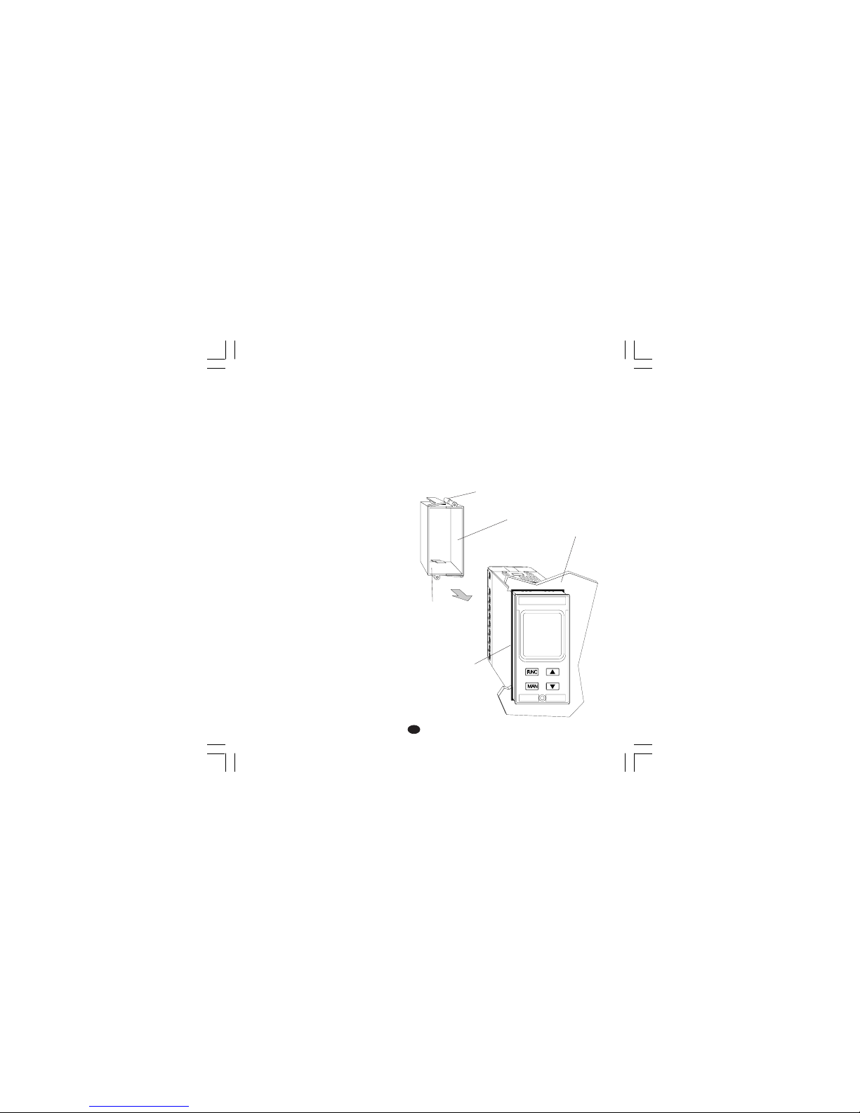
1
II
II
I
MONTAGGIOMONTAGGIO
MONTAGGIOMONTAGGIO
MONTAGGIO
Per il montaggio, scegliere un luogo che abbia le
seguenti caratteristiche:
1) sia facilmente accessibile anche sul retro
2) sia esente da vibrazioni o urti
3) non siano presenti gas corrosivi (gas solfurei,
amoniaca, ecc...)
4) non ci sia presenza di acqua o altri liquidi
5) la temperatura ambiente sia compresa tra 0 e
50 °C
6) l'umidità relativa dell'aria sia compresa trà 20 e
85 % RH e che non ci sia condensa.
Lo strumento può essere montato su un pannello
di spessore fino a 15 mm dopo aver eseguito un
foro rettangolare da 45 x 92 mm.
Per le dimensioni di ingombro e foratura vedere
Fig. 2.
La rugosità superficiale del pannello deve essere
migliore di 6,3 µmm.
Lo strumento è fornito di guarnizione in gomma
da pannello (da 50 a 60 Sh).
Per garantire la protezione IP65 e NEMA 4,
inserire la guarnizione, fornita con l'apparecchio,
tra lo strumento ed il pannello (vedere figura 1).
Per fissare lo strumento al pannello, procedere
come segue:
1) infilare la guarnizione sulla custodia dello
strumento.
2) inserire lo strumento nella foratura
3) mantenendo lo strumento ben appoggiato al
pannello, inserire la bretella di fissaggio.
4) utilizzando un cacciavite, serrare le viti con una
coppia compresa trà 0.3 e 0.4 Nm.
pannello
bretella
vite
vite
guarnizione
Fig. 1
Nuovo-1 16/02/2005, 14.241
Page 77
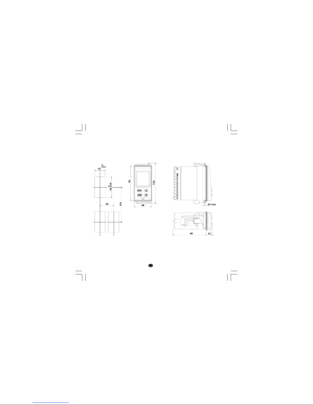
2
II
II
I
DIMENSIONI E FORATURADIMENSIONI E FORATURA
DIMENSIONI E FORATURADIMENSIONI E FORATURA
DIMENSIONI E FORATURA
Fig. 2
Nuovo-1 16/02/2005, 14.242
Page 78
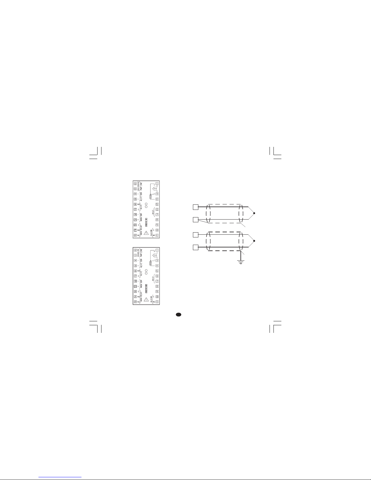
3
II
II
I
COLLEGAMENTI ELETTRICICOLLEGAMENTI ELETTRICI
COLLEGAMENTI ELETTRICICOLLEGAMENTI ELETTRICI
COLLEGAMENTI ELETTRICI
I collegamenti devono essere effettuati dopo che
la custodia dello strumento è stata regolarmente
montata sul pannello.
Fig. 3.A MORSETTIERA POSTERIORE (per i
modelli 100/240 V ca)
Fig. 3.B MORSETTIERA POSTERIORE (per i
modelli 24 V cc/ca)
A) INGRESSI DI MISURAA) INGRESSI DI MISURA
A) INGRESSI DI MISURAA) INGRESSI DI MISURA
A) INGRESSI DI MISURA
NOTANOTA
NOTANOTA
NOTA: Componenti esterni (es. barriere zener)
collegati tra il sensore ed i terminali di ingresso
dello strumento possono causare errori di misura
dovuti ad una impedenza troppo elevata o non
bilanciata oppure alla presenza di correnti di
perdita.
INGRESSO PER TERMOCOPPIAINGRESSO PER TERMOCOPPIA
INGRESSO PER TERMOCOPPIAINGRESSO PER TERMOCOPPIA
INGRESSO PER TERMOCOPPIA
Fig. 4 COLLEGAMENTO DI TERMOCOPPIE
NOTENOTE
NOTENOTE
NOTE:
1) Non posare i cavi dei segnali parallelamente o
vicino a cavi di potenza o a sorgenti di disturbi.
2) Per il collegamento della TC usare cavo di
compensazione/estensione appropriato,
preferibilmente schermato.
3) Quando si usa cavo schermato, lo schermo
deve essere collegato a terra ad una sola
estremità.
1
3
+
_
1
3
+
_
Schermo
Schermo
Nuovo-1 16/02/2005, 14.243
Page 79
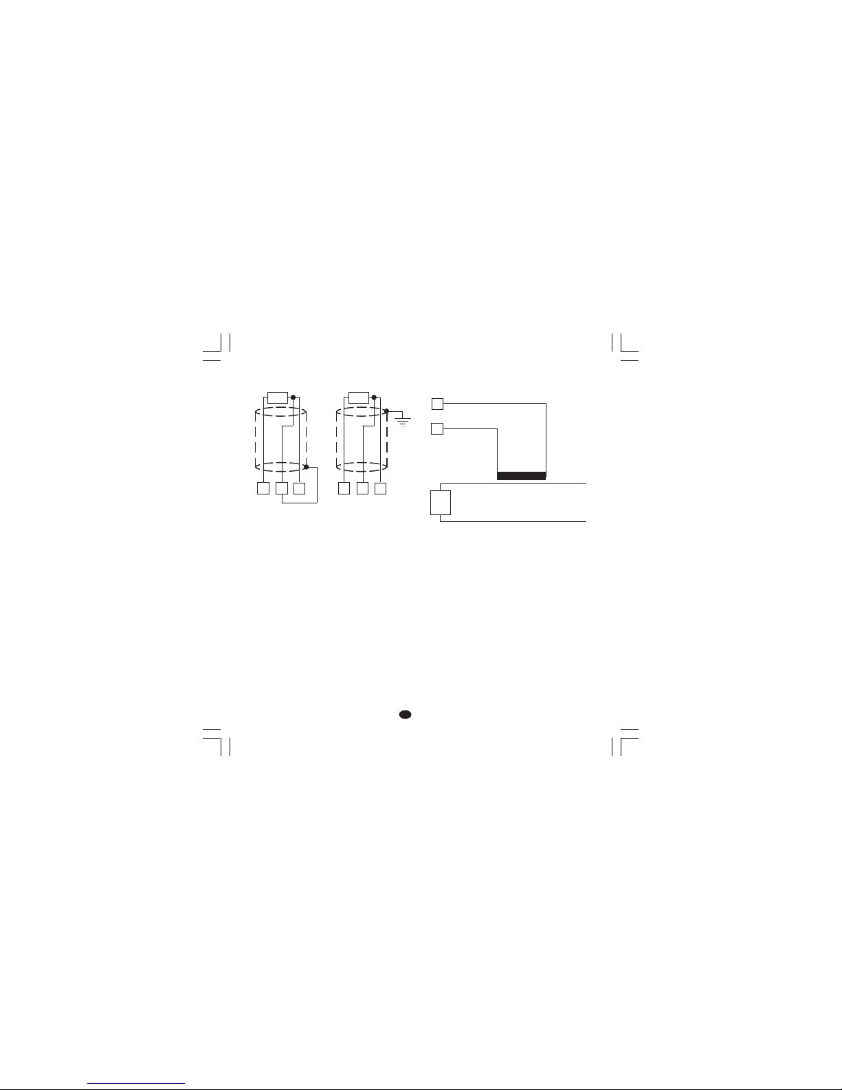
4
II
II
I
INGRESSO PER TERMORESISTENZAINGRESSO PER TERMORESISTENZA
INGRESSO PER TERMORESISTENZAINGRESSO PER TERMORESISTENZA
INGRESSO PER TERMORESISTENZA
Fig. 5 COLLEGAMENTO DI
TERMORESISTENZE
NOTENOTE
NOTENOTE
NOTE:
1) Non posare i cavi dei segnali parallelamente o
vicino a cavi di potenza o a sorgenti di disturbi.
2) Fare attenzione alla resistenza di linea, una
resistenza di linea eccessivamente alta
(superiore a 20 Ω/filo) può causare errori di
misura.
3) Quando si usa cavo schermato, lo schermo
deve essere collegato a terra ad una sola
estremità.
4) I 3 fili devono avere la stessa impedenza.
B) INGRESSO DA TRASFORMATOREB) INGRESSO DA TRASFORMATORE
B) INGRESSO DA TRASFORMATOREB) INGRESSO DA TRASFORMATORE
B) INGRESSO DA TRASFORMATORE
AMPEROMETRICOAMPEROMETRICO
AMPEROMETRICOAMPEROMETRICO
AMPEROMETRICO
Fig. 6 COLLEGAMENTO DEL
TRASFORMATORE AMPEROMETRICO
Nota:
1) L'impedenza di ingresso è pari a 10 Ω.
2) La massima corrente di ingresso è pari a 50
mA (50 / 60 Hz).
4
RTD
13 4
RTD
13
6
7
Trasformatore
amperometrico
Carico
Nuovo-1 16/02/2005, 14.244
Page 80
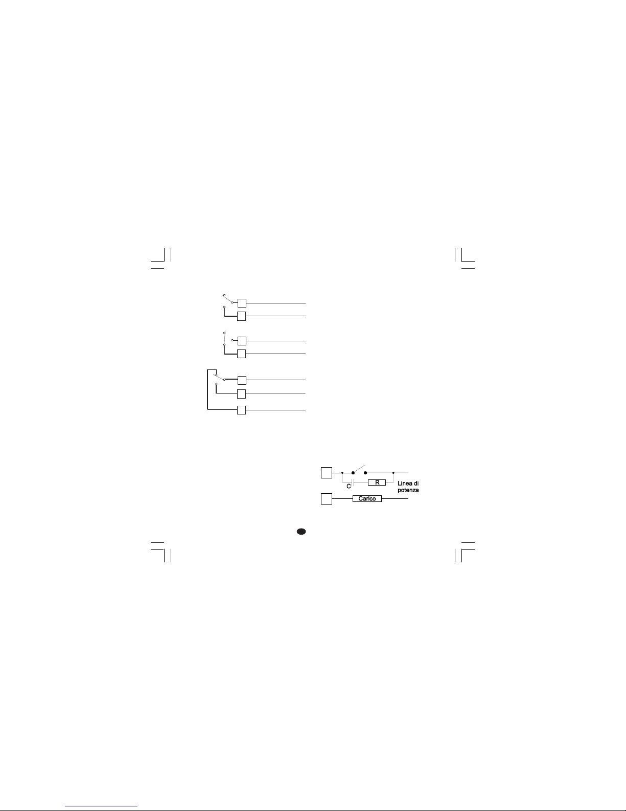
5
II
II
I
NOTENOTE
NOTENOTE
NOTE:
1) Per evitare il rischio di scosse elettriche collegare
la linea di potenza solo dopo aver effettuato tutti
gli altri collegamenti.
2) Per i collegamenti di potenza, utilizzare cavi No
16 AWG o maggiori adatti per una temperatura di
almeno 75 °C.
3) Utilizzare solo conduttori di rame.
4) Non posare i cavi della potenza parallelamente o
vicino a cavi dei segnali.
5) L'uscita a relè e quella SSR sono entrambe
disponibili. Quando si utilizza l'uscita a relè, è
necessario disattivare l'uscita SSR (vedere
capitolo "Impostazioni hardware preliminari").
Le raccomandazioni che seguono possono
evitare seri problemi causati dal utilizzo dell'uscita
3 o del contatto NC dell'uscita 1 per pilotare
carichi induttivi.
CARICHI INDUTTIVICARICHI INDUTTIVI
CARICHI INDUTTIVICARICHI INDUTTIVI
CARICHI INDUTTIVI
Nella commutazione di carichi induttivi si possono
generare transitori e disturbi che possono pregiudicare le prestazioni dello strumento.
Problemi analoghi possono essere generati dalla
commutazione di carichi tramite un contatto
esterno in serie al contatto di uscita dello
strumento.
Fig. 8 CONTATTO ESTERNO IN SERIE AL
CONTATTO DI USCITA DELLO STRUMENTO
C) USCITE A RELEC) USCITE A RELE
C) USCITE A RELEC) USCITE A RELE
C) USCITE A RELE
Fig. 7 COLLEGAMENTO DELLE USCITE A
RELE
L'uscita 2 ed il contatto NO dell'uscita 1 sonoi
protetti, tramite varistori, verso carichi che abbiano
componente induttiva fino a 0,5 A.
La portata del contatto relativo all'uscita 1 è pari a
3A/250V c.a. su carico resistivo.
La portata dei contatti relativi alle uscite 2 e 3
sono pari a 2 A/250V c.a. su carico resistivo.
Il numero delle operazioni è pari a 1 x 10
5
alla
portata specificata.
21
OUT 1
20
C
NO
22
NC
10
11
AL2/HBD
(OUT 3)
C - OUT 3
NO - OUT 3
16
17
AL1/COOL
(OUT 2)
OUT 2
C - OUT 2
NO/NC
[vedere Fig.11 (J303)]
Nuovo-1 16/02/2005, 14.245
Page 81
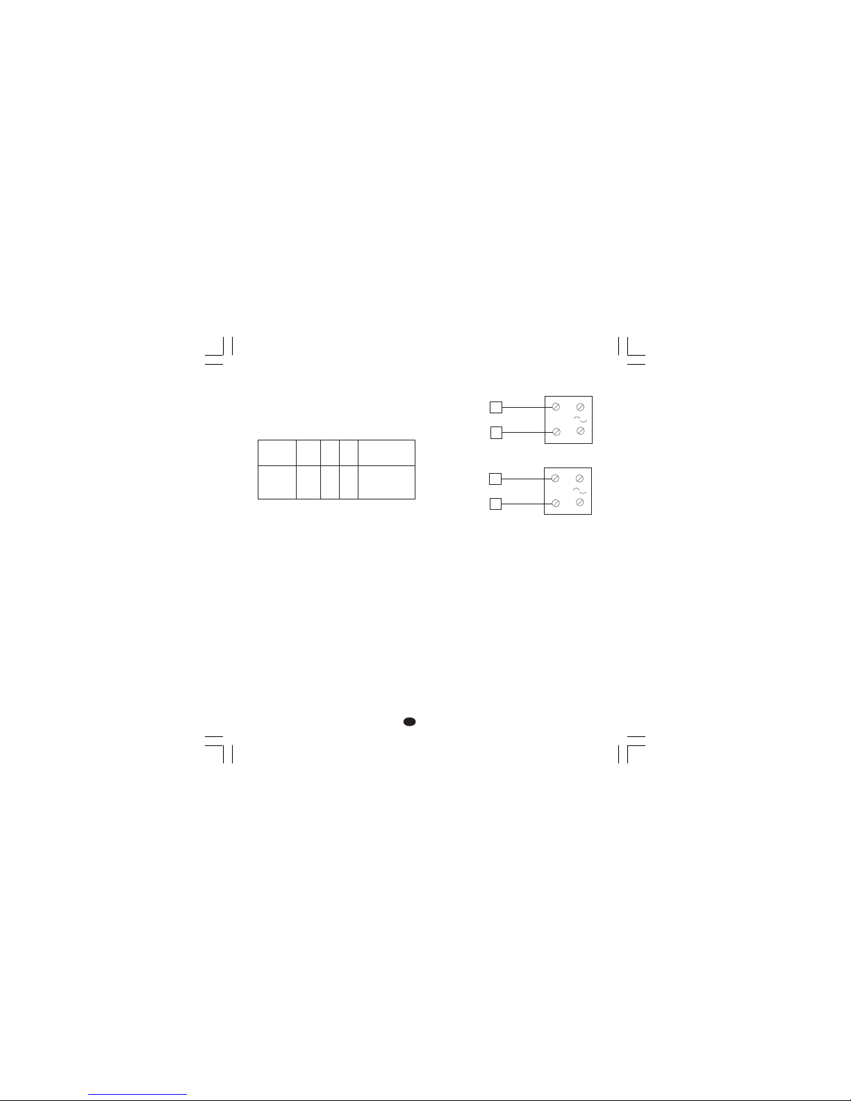
6
II
II
I
In questi casi si raccomanda di collegare un filtro
RC in parallelo al contatto esterno (oppure al
contatto interno non protetto) come indicato in
fig. 8.
Il valore della capacità (C) e del resistore (R)
sono indicati nella tabella seguente.
In tutti i casi i cavi collegati con le uscite a relè
devono rimanere il piu lontano possibile dai cavi
dei segnali.
D) USCITA LOGICA PER IL COMANDO DI SSRD) USCITA LOGICA PER IL COMANDO DI SSR
D) USCITA LOGICA PER IL COMANDO DI SSRD) USCITA LOGICA PER IL COMANDO DI SSR
D) USCITA LOGICA PER IL COMANDO DI SSR
Fig. 9 COLLEGAMENTO PER IL
PILOTAGGIO DI RELE A STATO
SOLIDO.
Questa è una uscita a tempo proporzionale.
Livello logico 0Livello logico 0
Livello logico 0Livello logico 0
Livello logico 0: Vout < 0.5 V c.c.
Livello logico 1Livello logico 1
Livello logico 1Livello logico 1
Livello logico 1: Corrente massima = 20 mA.
- 14 V
+ 20 % @ 20 mA
- 24 V
+ 20 % @ 1 mA.
NOTENOTE
NOTENOTE
NOTE:
1) Queste uscite NON sono isolate.
Un isolamento doppio o rinforzato tra lo
strumento e la linea di potenza deve essere
assicurato dal relè a stato solido esterno.
2) l'uscita a relè e quella SSR sono entrambe
disponibili. Quando si utilizza l'uscita SSR, è
necessario disattivare l'uscita relè (vedere
capitolo "Impostazioni hardware preliminari").
CARICO
(mA)
<40 mA
<150 mA
<0.5 A
C
(µF)
0.047
0.1
0.33
R
(Ω)
100
22
47
P.
(W)
1/2
2
2
TENSIONE
DI LAVORO
260 V AC
260 V AC
260 V AC
Relè a stato solido
Relè a stato solido
_
+
_
+
_
_
+
+
18
19
14
15
OUT 1
OUT 2
(AL1/Cool.)
Nuovo-1 16/02/2005, 14.246
Page 82

7
II
II
I
13
R (S,T)
R (S,T)
N
12
N
Rete
da 100 V a 240 V ca (50/60Hz)
oppure 24 V ca/cc
E) ALIMENTAZIONEE) ALIMENTAZIONE
E) ALIMENTAZIONEE) ALIMENTAZIONE
E) ALIMENTAZIONE
Fig. 10 COLLEGAMENTO ALL'ALIMENTAZIONE
NOTENOTE
NOTENOTE
NOTE:
1) Prima di collegare lo strumento alla rete,
assicurarsi che la tensione di linea sia
corrispondente a quanto indicato nella targa di
identificazione dello strumento.
2) Per evitare il rischio di scosse elettriche collegare
l'alimentazione solo dopo aver effettuato tutti gli
altri collegamenti.
3) Per il collegamento alla rete, utilizzare cavi No 16
AWG o maggiori adatti per una temperatura di
almeno 75 °C.
4) Utilizzare solo conduttori di rame.
5) Non posare i cavi dei segnali parallelamente o
vicino a cavi di potenza o a sorgenti di disturbi.
6) Per l'alimentazione 24 V c.c. la polarità non ha
importanza.
7) I circuiti di alimentazione NON sono protetti da
fusibile, pertanto si consiglia di prevederne uno
esterno tipo T, 1 A, 250 V.
Se il fusibile dovesse risultare danneggiato, è
consigliabile far verificare l'intero circuito di alimentazione. Per questa ragione si consiglia di
spedire l'apparecchio al fornitore.
8) Le normative sulla sicurezza relative ad
apparecchiature collegate permanentemente
all'alimentazione richiedono:
- un interruttore o disgiuntore va compreso nel-
l'impianto elettrico dell'edificio;
- esso deve trovarsi in stretta vicinanza dell'ap-
parecchio ed essere facilmente raggiungibile
da parte dell'operatore;
- Deve essere marcato come il dispositivo di
interruzione dell'apparecchio.
NOTANOTA
NOTANOTA
NOTA: un singolo interruttore o disgiuntore puo
comandare piu apparecchi.
9) Se l'alimentazione prevede il neutro, collegarlo al
terminale 12.
Nuovo-1 16/02/2005, 14.247
Page 83
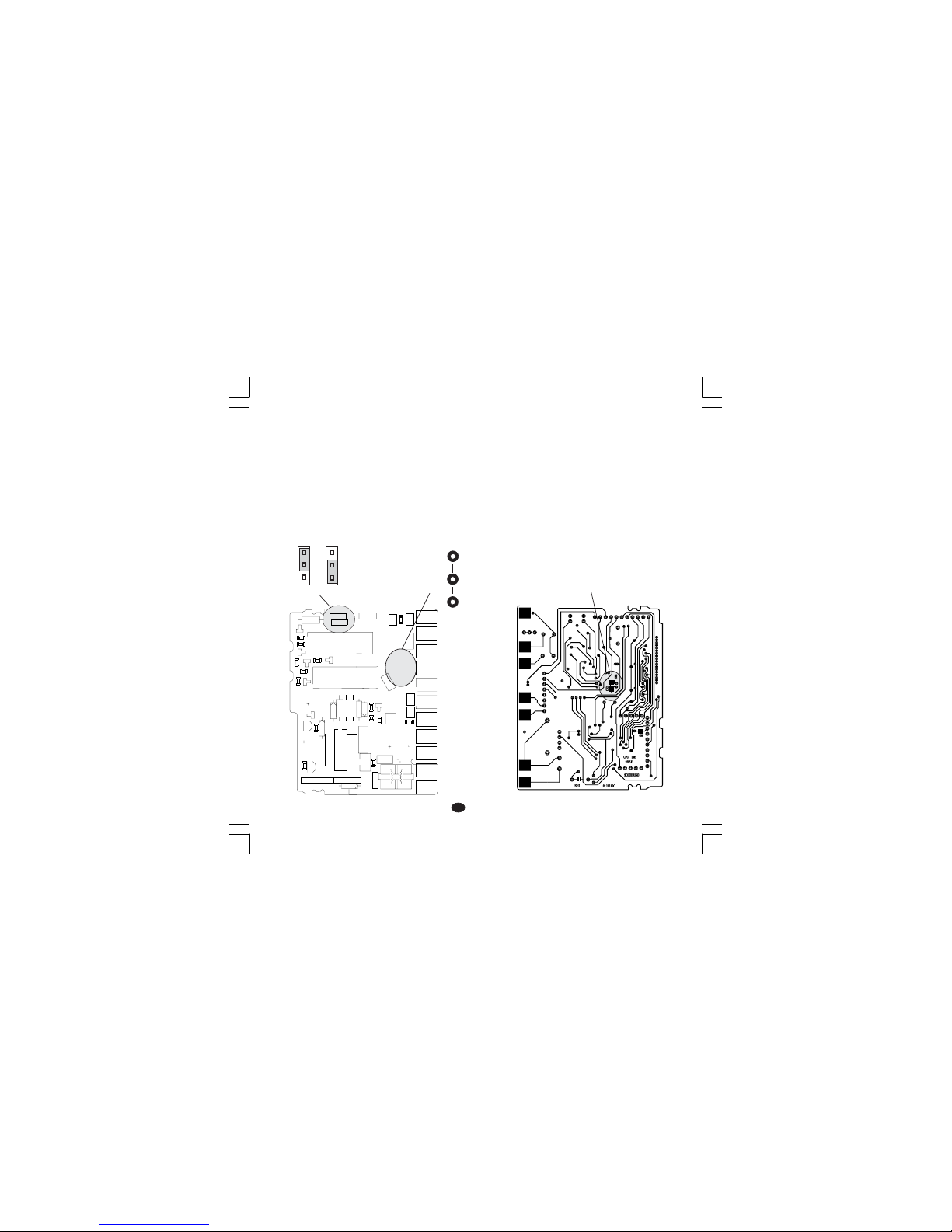
8
II
II
I
IMPOSTAZIONI HARDWAREIMPOSTAZIONI HARDWARE
IMPOSTAZIONI HARDWAREIMPOSTAZIONI HARDWARE
IMPOSTAZIONI HARDWARE
PRELIMINARIPRELIMINARI
PRELIMINARIPRELIMINARI
PRELIMINARI
1) Sfilare lo strumento dalla custodia.
2) Per le uscite 1 e 2, selezionare il tipo di uscita
desiderata impostando i ponticelli J 304 e J305
J304 (AL1, Cool.) 1-2 = SSR 2-3 = Relè
J305 (Uscita principale) 1-2 = SSR 2-3 = Relè
3) per l'uscita 2 è possibile selezionare il contatto
utilizzato (NO o NC) tramite il ponticello J303
J303 (AL1, Cool.) 1-2 = Out NO 2-3 = Out NC
Nota Nota
Nota Nota
Nota : J303 è un ponticello a saldare e viene
eseguito sul lato saldatura.
Fig 11
APERTURA DEI COLLEGAMENTI INAPERTURA DEI COLLEGAMENTI IN
APERTURA DEI COLLEGAMENTI INAPERTURA DEI COLLEGAMENTI IN
APERTURA DEI COLLEGAMENTI IN
INGRESSOINGRESSO
INGRESSOINGRESSO
INGRESSO
Questo strumento è in grado di rilevare l'apertura
del circuito di ingresso per ingressi da TC o RTD.
L'apertura dell'ingresso RTD viene indicato come
una condizione di overrange.
Per l'ingresso da termocoppia è possibile
selezionare l'indicazione di overrange (standard)
chiudendo CH2 ed aprendo SH2 oppure
l'indicazione di underrange aprendo CH2 e
chiudendo SH2.
Entrambe le piazzole sono situate sul lato
saldatura della scheda CPU (Vedere disegno).
Fig. 12
1
1
1
23
4
+
-
+
B
C
E
I
1
3
4
7
1
1
XY00
I
1
2
3
12
3
45
12
345
J301
J302
L305
R301
R303
D
3
0
5
C308
C306
C307
R305
C312
C310
D307
R308
C309
PZ12
PZ13
PZ14
PZ15
PZ16
PZ19
PZ20
PZ21
PZ22
R307
R306
Q302
U302
TR301
J304
J305
Y301
D306
D308
D304
U301
PZ18
PZ17
C301
C
3
0
4
J303
C303
C311
C302
C305
C314
C313
L304
L301
L303
L302
R309
R310
R312
R314
R311
R302
R304
R313
Q303
Q305
D302
Q301
Q304
D301
D310
K302
K301
J 303
1
3
J304 J305
1
CH2
SH2
Nuovo-1 16/02/2005, 14.248
Page 84

9
II
II
I
NOTE GENERALI di configurazione.NOTE GENERALI di configurazione.
NOTE GENERALI di configurazione.NOTE GENERALI di configurazione.
NOTE GENERALI di configurazione.
FUNC = Consente di memorizzare il nuovo
valore del parametro selezionato e
passare al parametro successivo
(ordine crescente).
SMRT = Consente di visualizzare i parametri in
ordine decrescente senza memorizzare i nuovi valori.
= Consente di aumentare il valore del
parametro selezionato.
= Consente di diminuire il valore del
parametro selezionato.
PROCEDURE DI CONFIGURAZIONEPROCEDURE DI CONFIGURAZIONE
PROCEDURE DI CONFIGURAZIONEPROCEDURE DI CONFIGURAZIONE
PROCEDURE DI CONFIGURAZIONE
1) Sfilare lo strumento dalla custodia.
2) Posizionare lo switch V2 (vedere la figura
seguente) in posizione aperta.
Fig.13
3) Reinserire lo strumento.
4) Alimentare lo strumento; il display superiore
indicherà "CnF".
ATTENZIONEATTENZIONE
ATTENZIONEATTENZIONE
ATTENZIONE: Se lo strumento dovesse
visualizzare l'indicazione "CAL" premere
immediatamente il tasto per tornare alla
fase di configurazione.
5) Premere il tasto FUNC. Il display inferiore
visualizzerà il codice del parametro selezionato
mentre il display superiore ne visualizzerà
l'impostazione.
P1 - Tipo di ingresso e scala standardP1 - Tipo di ingresso e scala standard
P1 - Tipo di ingresso e scala standardP1 - Tipo di ingresso e scala standard
P1 - Tipo di ingresso e scala standard
0 = TC tipo L scala 0 / +800 °C
1 = TC tipo J scala 0 / +800 °C
2 = TC tipo K scala 0 / +999 °C
3 = TC tipo N scala 0 / +999 °C
4 = RTD tipo Pt 100 scala -199 / +500 °C
5 = RTD tipo Pt 100 scala -19.9 / +99.9 °C
6 = TC tipo T scala 0 / +400 °C
8 = TC tipo L scala 0 / +999 °F
9 = TC tipo J scala 0 / +999 °F
10 = TC tipo K scala 0 / +999 °F
11 = TC tipo N scala 0 / +999 °F
12 = RTD tipo Pt 100 scala -199 / +999 °F
13 = TC tipo T scala 0 / +752 °F
P2 = Inizio scalaP2 = Inizio scala
P2 = Inizio scalaP2 = Inizio scala
P2 = Inizio scala
Non disponibile se P1 = 5
Valore di inizio scala utilizzato dall'algoritmo PID
per i calcoli dell'ampiezza del campo di lavoro.
P2 è programmabile all'interno del campo di
ingresso selezionato tramite P1.
Quando il parametro P2 viene modificato, lo
strumento assegna automaticamente al
parametro rL il nuovo valore di P2.
V2
Nuovo-1 16/02/2005, 14.249
Page 85

10
II
II
I
P3 = Fondo scalaP3 = Fondo scala
P3 = Fondo scalaP3 = Fondo scala
P3 = Fondo scala
Non disponibile se P1 = 5
Valore di fondo scala utilizzato dall'algoritmo PID
per i calcoli dell'ampiezza del campo di lavoro.
P3 è programmabile all'interno del campo di
ingresso selezionato tramite P1.
Quando il parametro P3 viene modificato, lo
strumento assegna automaticamente al
parametro rH il nuovo valore di P3.
NOTANOTA
NOTANOTA
NOTA: l'ampiezza del campo di lavoro (P3 - P2)
deve essere superiore o uguale a:
- 300 °C o 600 °F per ingresso da TC;
- 100 °C o 200 °F per ingresso da RTD.
P4 = Configurazione usciteP4 = Configurazione uscite
P4 = Configurazione usciteP4 = Configurazione uscite
P4 = Configurazione uscite
H = Riscaldamento
HC = Riscald./Raffredd.
P5 = Tipo uscita principaleP5 = Tipo uscita principale
P5 = Tipo uscita principaleP5 = Tipo uscita principale
P5 = Tipo uscita principale
rEL = Uscita a relè.
SSr = Uscita per SSR.
NOTANOTA
NOTANOTA
NOTA:
Impostando P5 = rEL, Il parametro C verrà
forzato ad assumere il
valore 20 secondi.
Impostando P5=SSr, Il parametro C verrà
forzato ad assumere il
valore 2 secondi.
P6 = Tipo uscita raffreddamentoP6 = Tipo uscita raffreddamento
P6 = Tipo uscita raffreddamentoP6 = Tipo uscita raffreddamento
P6 = Tipo uscita raffreddamento
Disponibile solo se P4 = HC
AIr = aria
OIL = olio
H2O = acqua
NOTANOTA
NOTANOTA
NOTA:
Impostando P6 = Air, Il parametro C2 verrà
forzato ad assumere il
valore 10 secondi mentre il
parametro rC assumerà il
valore 1.00.
Impostando P6=OiL, Il parametro C2 verrà forza-
to ad assumere il valore 4
secondi mentre il parametro
rC assumerà il valore 0.8.
Impostando P6=H2O, Il parametro C2 verrà forza-
to ad assumere il valore 2
secondi mentre il parametro
rC assumerà il valore 0.4.
P7 = Allarme 1P7 = Allarme 1
P7 = Allarme 1P7 = Allarme 1
P7 = Allarme 1
Disponibile solo se P4 = H.
0 = Non previsto
1 = Allarme di processo
2 = Allarme di banda
3 = Allarme di deviazione
P8 = Modo operativo allarme 1P8 = Modo operativo allarme 1
P8 = Modo operativo allarme 1P8 = Modo operativo allarme 1
P8 = Modo operativo allarme 1
Disponibile solo se P7 è diverso da 0 e P4 = H.
H.A. = Allarme di massima (fuori banda) con
riarmo automatico.
L.A. = Allarme di minima (dentro la banda) con
riarmo automatico.
H.L. = Allarme di massima (fuori banda) con
riarmo manuale.
L.L. = Allarme di minima (dentro la banda) con
riarmo manuale.
P9 = Mascheratura allarme 1P9 = Mascheratura allarme 1
P9 = Mascheratura allarme 1P9 = Mascheratura allarme 1
P9 = Mascheratura allarme 1
Disponibile solo se P7 è diverso da 0 e P4 = H.
OFF = mascheratura disabilitata
ON = mascheratura abilitata
NOTANOTA
NOTANOTA
NOTA: la mascheratura inibisce l'azione degli
allarmi all'accensione o, per i soli allarmi di
banda e di deviazione, dopo le modifiche del set
point.
Gli allarmi verranno riattivati automaticamente quando l'iniziale condizione di allarme è scomparsa.
Nuovo-1 16/02/2005, 14.2410
Page 86
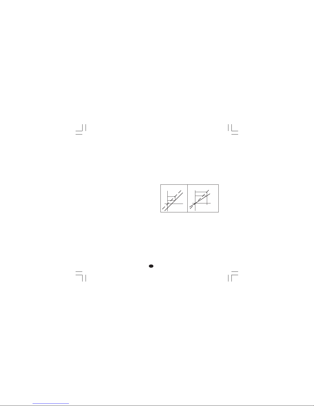
11
II
II
I
P10 = Allarme 2P10 = Allarme 2
P10 = Allarme 2P10 = Allarme 2
P10 = Allarme 2
0 = Non previsto
1 = Allarme di processo
2 = Allarme di banda
3 = Allarme di deviazione
L'uscita dell'allarme 2 è in OR con l'uscita della
funzione HBD (vedere parametro P16).
P11 = Modo operativo allarme 2 e riarmoP11 = Modo operativo allarme 2 e riarmo
P11 = Modo operativo allarme 2 e riarmoP11 = Modo operativo allarme 2 e riarmo
P11 = Modo operativo allarme 2 e riarmo
dell'allarme HBDdell'allarme HBD
dell'allarme HBDdell'allarme HBD
dell'allarme HBD
Disponibile solo se P10 è diverso da 0 o P16 è
diverso da OFF.
H.A. = Allarme di massima (fuori banda) con
riarmo automatico.
L.A. = Allarme di minima (dentro la banda) con
riarmo automatico.
H.L. = Allarme di massima (fuori banda) con
riarmo manuale.
L.L. = Allarme di minima (dentro la banda) con
riarmo manuale.
NOTANOTA
NOTANOTA
NOTA: l'allarme HBD è sempre un allarme di
minima ma assume il tipo di riarmo
selezionato per l'allarme 2.
P12 = Mascheratura allarme 2P12 = Mascheratura allarme 2
P12 = Mascheratura allarme 2P12 = Mascheratura allarme 2
P12 = Mascheratura allarme 2
Disponibile solo se P10 è diverso da 0.
OFF = mascheratura disabilitata
ON = mascheratura abilitata
Per ulteriori dettagli vedere parametro P9.
P13 = Tipo di OFFSET sulla misuraP13 = Tipo di OFFSET sulla misura
P13 = Tipo di OFFSET sulla misuraP13 = Tipo di OFFSET sulla misura
P13 = Tipo di OFFSET sulla misura
P13 = 0 OFFSET (P14) costante su
tutto il campo.
P13 diverso da 0 P13 indica il punto di
applicazione del valore di
offset impostato con il
parametro P14.
NOTANOTA
NOTANOTA
NOTA: i parametri P13 e P14 NON modificano i limiti
di misura o di visualizzazione dello strumento pertanto il superamento di uno di questi limiti produce
una segnalazione di fuori campo.
P14 = Valore di OFFSETP14 = Valore di OFFSET
P14 = Valore di OFFSETP14 = Valore di OFFSET
P14 = Valore di OFFSET
Se P13 = 0, P 14 è programmabile, in unità
ingegneristiche, tra -20 % e +20 %
del campo di ingresso (P1).
Se P13 è diverso da 0, P 14 è programmabile in
unità ingegneristiche tra -20 % e +
20 % del valore di P13.
NOTANOTA
NOTANOTA
NOTA: il parametro P14 non puo assumere un
valore inferiore a -199 unità.
P15 = Soglia della funzione “Soft Start”P15 = Soglia della funzione “Soft Start”
P15 = Soglia della funzione “Soft Start”P15 = Soglia della funzione “Soft Start”
P15 = Soglia della funzione “Soft Start”
(partenza morbida).(partenza morbida).
(partenza morbida).(partenza morbida).
(partenza morbida).
Valore di soglia, in unità ingegneristiche, utilizzata
dallo strumento per l'inserimento automatico della
funzione "Soft start" (limitazione temporizzata
della potenza di uscita).
All'accensione dello strumento, se il valore
misurato è inferiore alla soglia programmata, lo
strumento inserirà automaticamente la limitazione
della potenza di uscita e la manterrà per un
tempo programmato (vedere il parametro "tOL" al
paragrafo "PARAMETRI OPERATIVI").
All'accensione, se il parametro "tOL" è uguale ad
infinito (limitazione sempre inserita), lo strumento
ignora questo parametro.
P13 = 0
Visualizz.
Curva
corretta
Ingresso
P14
Curva
reale
P13
Visualizz.
P14
Ingresso
Curva
reale
Curva
corretta
Nuovo-1 16/02/2005, 14.2411
Page 87

12
II
II
I
P16 =P16 =
P16 =P16 =
P16 =
Misura della corrente consumata dalMisura della corrente consumata dal
Misura della corrente consumata dalMisura della corrente consumata dal
Misura della corrente consumata dal
carico comandato tramite l'uscitacarico comandato tramite l'uscita
carico comandato tramite l'uscitacarico comandato tramite l'uscita
carico comandato tramite l'uscita
principale (HBD)principale (HBD)
principale (HBD)principale (HBD)
principale (HBD)
OFF = Misura non abilitata
n.O. = Misura abilitata su periodo ON (stato 1
per SSR o carico pilotato da contatto NO)
n.C. = Misura abilitata su periodo OFF (stato 0
per SSR o carico pilotato da contatto NC)
P17 =P17 =
P17 =P17 =
P17 =
Fondo scala trasformatoreFondo scala trasformatore
Fondo scala trasformatoreFondo scala trasformatore
Fondo scala trasformatore
amperometricoamperometrico
amperometricoamperometrico
amperometrico
Disponibile solo quando P16 è diverso da OFF.
10 = 10 A fondo scala (risoluzione 0.1 A)
25 = 25 A fondo scala (risoluzione 1 A)
50 = 50 A fondo scala (risoluzione 1 A)
100 = 100 A fondo scala (risoluzione 1 A)
P18 = chiave di accesso ai parametri diP18 = chiave di accesso ai parametri di
P18 = chiave di accesso ai parametri diP18 = chiave di accesso ai parametri di
P18 = chiave di accesso ai parametri di
controllocontrollo
controllocontrollo
controllo
0 = parametri sempre accessibili
1 = SP può essere modificato mentre tutti gli altri
parametri sono sempre protetti
da 2 a 499 = SP può essere sempre modificato
mentre questo codice numerico
consente l'accesso o l'inibizione
della modifica dei rimanenti
parametri operativi.
da 500 a 999 = SP, A1 e A2 sono sempre
modificabili mentre questo codice
numerico consente l'accesso o
l'inibizione della modifica dei
rimanenti parametri operativi.
NOTANOTA
NOTANOTA
NOTA: dopo la pressione del tasto FUNC, NON
sarà piu possibile visualizzare il valore di questo
parametro. Se non si conosce il vecchio codice
di sicurezza impostarne uno nuovo.
La procedura di configurazione standard è
completata e lo strumento visualizzerà "
-.-.-."
su entrambi i display.
Se non si desidera eseguire altre impostazioni,
premere FUNC, lo strumento tornerà all'inizio
della procedura di configurazione.
Se si desidera eseguire una configurazione
completa, premere i tasti o ed impostare il
valore 217 sul display superiore.
Premere il tasto FUNC; lo strumento inizierà la
procedura di configurazione ausiliaria
visualizzando i seguenti parametri addizionali.
P19 - Azione dell'uscita principaleP19 - Azione dell'uscita principale
P19 - Azione dell'uscita principaleP19 - Azione dell'uscita principale
P19 - Azione dell'uscita principale
Disponibile solo quando P4 = H.
r = Inversa (riscaldamento)
d = Diretta (raffreddamento)
Nota : quando P4 = HC, questa parametro viene
forzato a "r".
P21 - Azione del relè relativo all'allarme 1P21 - Azione del relè relativo all'allarme 1
P21 - Azione del relè relativo all'allarme 1P21 - Azione del relè relativo all'allarme 1
P21 - Azione del relè relativo all'allarme 1
Questo parametro viene visualizzato solo quando
P7 è diverso da 0 e P4 è uguale a H.
r = inversa (relè de-energizzato in condizione di
allarme).
d = Diretta (relè energizzato in condizione di
allarme)
t
Ingresso
t
Uscita
t
Ingresso
t
Uscita
Inversa Diretta
Nuovo-1 16/02/2005, 14.2412
Page 88

13
II
II
I
P22 - Azione del relè relativo all'allarme 2P22 - Azione del relè relativo all'allarme 2
P22 - Azione del relè relativo all'allarme 2P22 - Azione del relè relativo all'allarme 2
P22 - Azione del relè relativo all'allarme 2
Questo parametro NON viene visualizzato solo
quando P10 è uguale a 0 e P16 è uguale a
"OFF".
r = inversa (relè de-energizzato in condizione di
allarme).
d = Diretta (relè energizzato in condizione di
allarme)
P23 - Modifica automatica del "guadagnoP23 - Modifica automatica del "guadagno
P23 - Modifica automatica del "guadagnoP23 - Modifica automatica del "guadagno
P23 - Modifica automatica del "guadagno
relativo di raffreddamento".relativo di raffreddamento".
relativo di raffreddamento".relativo di raffreddamento".
relativo di raffreddamento".
Disponibile solo quando P4=HC.
OFF = La funzione SMART
NON NON
NON NON
NON modificherà il
valore del parametro "guadagno relativo
di raffreddamento".
ON = La funzione SMART modificherà il valore
del parametro "guadagno relativo di
raffreddamento".
P24 - Massima velocità di variazione delP24 - Massima velocità di variazione del
P24 - Massima velocità di variazione delP24 - Massima velocità di variazione del
P24 - Massima velocità di variazione del
segnale di uscita.segnale di uscita.
segnale di uscita.segnale di uscita.
segnale di uscita.
Questo parametro consente di impostare la
massima velocità di variazione del segnale di
uscita.
P24 è programmabile tra 1 e 10 % del campo di
uscita al secondo.
Oltre il 10 %, il display superiore si spegne e lo
strumento non limiterà la velocità di variazione.
P25 - Visualizzazione dei parametri protettiP25 - Visualizzazione dei parametri protetti
P25 - Visualizzazione dei parametri protettiP25 - Visualizzazione dei parametri protetti
P25 - Visualizzazione dei parametri protetti
Questo parametro viene visualizzato solo se P18
è diverso da 0.
OFF = Lo strumento NON visualizzerà i
parametri protetti.
ON = tutti i parametri potranno essere
visualizzati.
P26 - SMART abilitato/ disabilitatoP26 - SMART abilitato/ disabilitato
P26 - SMART abilitato/ disabilitatoP26 - SMART abilitato/ disabilitato
P26 - SMART abilitato/ disabilitato
0 = La funzione SMART è sempre
disabilitata.
1 = L'abilitazione e la disabilitazione della
funzione SMART
NON NON
NON NON
NON è protetta dalla
chiave di sicurezza.
2 = L'abilitazione e la disabilitazione della
funzione SMART è protetta dalla chiave
di sicurezza.
P27 - Massimo valore di banda proporzionaleP27 - Massimo valore di banda proporzionale
P27 - Massimo valore di banda proporzionaleP27 - Massimo valore di banda proporzionale
P27 - Massimo valore di banda proporzionale
impostabile dalla funzione SMART.impostabile dalla funzione SMART.
impostabile dalla funzione SMART.impostabile dalla funzione SMART.
impostabile dalla funzione SMART.
Questo parametro viene visualizzato solo se P26
è diverso da 0.
Questo parametro può essere programmato tra il
valore di P28 o P29 e 99.9.
P28 - Minimo valore di banda proporzionaleP28 - Minimo valore di banda proporzionale
P28 - Minimo valore di banda proporzionaleP28 - Minimo valore di banda proporzionale
P28 - Minimo valore di banda proporzionale
impostabile dalla funzione SMART.impostabile dalla funzione SMART.
impostabile dalla funzione SMART.impostabile dalla funzione SMART.
impostabile dalla funzione SMART.
Questo parametro viene visualizzato solo se P26
è diverso da 0 e P4=H.
Questo parametro può essere programmato tra
1.0% ed il valore di P27.
P29 - Minimo valore di banda proporzionaleP29 - Minimo valore di banda proporzionale
P29 - Minimo valore di banda proporzionaleP29 - Minimo valore di banda proporzionale
P29 - Minimo valore di banda proporzionale
impostabile dalla funzione SMART per la solaimpostabile dalla funzione SMART per la sola
impostabile dalla funzione SMART per la solaimpostabile dalla funzione SMART per la sola
impostabile dalla funzione SMART per la sola
regolazione riscaldamento/raffreddamento.regolazione riscaldamento/raffreddamento.
regolazione riscaldamento/raffreddamento.regolazione riscaldamento/raffreddamento.
regolazione riscaldamento/raffreddamento.
Questo parametro viene visualizzato solo se P26
è diverso da 0 e P4=HC.
Questo parametro può essere programmato tra
1.5% ed il valore di P27.
Nuovo-1 16/02/2005, 14.2413
Page 89

14
II
II
I
P30 - Minimo valore di tempo integraleP30 - Minimo valore di tempo integrale
P30 - Minimo valore di tempo integraleP30 - Minimo valore di tempo integrale
P30 - Minimo valore di tempo integrale
impostabile dalla funzione SMART.impostabile dalla funzione SMART.
impostabile dalla funzione SMART.impostabile dalla funzione SMART.
impostabile dalla funzione SMART.
Questo parametro viene visualizzato solo se P26
è diverso da 0.
Questo parametro può essere programmato tra
00.1 (mm.s) e 02.0 (mm.s).
P31 = Estensione dell'anti-reset-wind upP31 = Estensione dell'anti-reset-wind up
P31 = Estensione dell'anti-reset-wind upP31 = Estensione dell'anti-reset-wind up
P31 = Estensione dell'anti-reset-wind up
Campo: da -30 a +30 % della banda
proporzionale.
NOTANOTA
NOTANOTA
NOTA: un valore positivo aumenta il limite
massimo della funzione (sopra il set point) mentre
un valore negativo abbassa il limite minimo della
funzione (sotto il set point).
La configurazione ausiliaria è completa e lo
strumento visualizzerà "CnF" sul display
superiore.
MODO OPERATIVOMODO OPERATIVO
MODO OPERATIVOMODO OPERATIVO
MODO OPERATIVO
1) Sfilare lo strumento dalla custodia.
2) Impostare il ponticello V2 (vedere fig. 13) in
posizione chiusa.
3) Re-inserire lo strumento.
4) Alimentare lo strumento.
Il display superiore visualizza il valore misurato
mentre quello inferiore mostra il valore di set point
impostato (questo stato viene definito "modo
normale di visualizzazione").
NotaNota
NotaNota
Nota: Quando al set point operativo è applicata una
rampa (parametro rP), il valore del set point
visualizzato potrebbe essere diverso da quello
operativo.
Premendo il tasto , se la funzione HBD è
configurata, l'uscita di controllo è abilitata e lo
strumento è in modo normale di visualizzazione, è
possibile visualizzare sul display inferiore il valore
della corrente consumata dal carico pilotato
tramite l'uscita 1 seguito dal simbolo A.
NOTANOTA
NOTANOTA
NOTA: questa visualizzazione NON è soggetta a
time out. Per tornare al modo normale di
visualizzazione premere nuovamente il
tasto .
Nuovo-1 16/02/2005, 14.2414
Page 90

15
II
II
I
INIBIZIONE DEL SEGNALE DI USCITAINIBIZIONE DEL SEGNALE DI USCITA
INIBIZIONE DEL SEGNALE DI USCITAINIBIZIONE DEL SEGNALE DI USCITA
INIBIZIONE DEL SEGNALE DI USCITA
Il TMS consente di inibire manualmente il segnale
di uscita onde poter interrompere la regolazione
(lo strumento funzionerà come semplice
indicatore).
Per inibire il segnale di uscita procedere come
segue:
1) Premere e mantenere premuto il tasto .
2) Premere il tasto FUNC.
3) Mantenere la pressione su entrambi i tasti per
un periodo superiore a 3 secondi.
Il display inferiore visualizzerà il messaggio "OFF"
e l'uscita di regolazione risulterà inibita.
Quando si desidera riattivare la regolazione
automatica, ripetere le azioni sopra viste ; lo
strumento ritornerà automaticamente in modo
"Visualizzazione Normale".
NOTA:NOTA:
NOTA:NOTA:
NOTA:1)Lo strumento memorizza lo stato di
inibizione dell'uscita.
2) Se il segnale di uscita viene inibito
quando la funzione SMART sta
eseguendo la prima parte dell'algoritmo
di autosintonizzazione (LED SMRT
lampeggiante), lo strumento abortirà
l'esecuzione dell'algoritmo e, quando si
tornerà al normale controllo, la funzione
SMART risulterà disabilitata.
Se il segnale di uscita viene inibito
quando la funzione SMART sta
eseguendo la parte di sintonizzazione
continua dell'algoritmo di
autosintonizzazione (LED SMRT acceso
fisso), lo strumento fermerà temporaneamente l'esecuzione dell'algoritmo e,
quando si tornerà al normale controllo, la
funzione SMART risulterà attiva.
ALGORITMO SMARTALGORITMO SMART
ALGORITMO SMARTALGORITMO SMART
ALGORITMO SMART
L'algoritmo SMART è un nuovo algoritmo di autosintonizzazione automatica. Lo SMART viene utilizzato dallo strumento per calcolare ed impostare
automaticamente i parametri di regolazione.
L'algoritmo SMART può essere sempre inserito
onde ottenere una continua ottimizzazione dei
parametri in funzione degli eventuali cambiamenti delle condizioni di impianto.
Per abilitare questa funzione, premere il tasto
SMRT per un tempo superiore a 1,5 s quando lo
strumento è in modo "Visualizzazione normale".
L'indicatore SMRT inizierà a lampeggiare o si
accenderà a luce fissa in funzione del tipo di
sintonizzazione in esecuzione.
Quando si desidera disattivare la funzione
SMART, premere semplicemente il tasto SMRT;
l'indicatore SMRT si spegnerà.
NOTENOTE
NOTENOTE
NOTE:
1) Quando la funzione SMART è attiva, il
guadagno relativo di raffreddamento (se
presente) sarà limitato all'interno dei seguenti
valori:
Elemento raffreddante Campo
Aria da 0.85 a 1.00
Olio da 0.80 a 0.90
Acqua da 0.30 a 0.60
2) La funzione SMART utilizza un'azione
derivativa pari ad 1/4 dell'azione integrale.
3) I limiti della banda proporzionale e del tempo
integrale impostabili dalla funzione SMART
sono programmabili tramite i parametri P27,
P28, P29 e P30 (vedere sezione 3).
4) L'attivazione/disattivazione della funzione
SMART puo essere protetta dalla chiave di
sicurezza(vedere parametro P18).
5) Quando la funzione SMART è attiva i
parametri Pb, ti e td non sono modificabili da
tastiera. Per il parametro rC vedere P23.
Nuovo-1 16/02/2005, 14.2415
Page 91

16
II
II
I
ALLARME DI MALFUNZIONAMENTO DELALLARME DI MALFUNZIONAMENTO DEL
ALLARME DI MALFUNZIONAMENTO DELALLARME DI MALFUNZIONAMENTO DEL
ALLARME DI MALFUNZIONAMENTO DEL
CARICO COMANDATO TRAMITE L'USCITACARICO COMANDATO TRAMITE L'USCITA
CARICO COMANDATO TRAMITE L'USCITACARICO COMANDATO TRAMITE L'USCITA
CARICO COMANDATO TRAMITE L'USCITA
PRINCIPALE PRINCIPALE
PRINCIPALE PRINCIPALE
PRINCIPALE
(allarme HBD) (allarme HBD)
(allarme HBD) (allarme HBD)
(allarme HBD)
..
..
.
Questo allarme consente di tenere sotto controllo
continuamente l'assorbimento del carico pilotato
tramite l'uscita principale e di generare un allarme
qualora il consumo risultasse inferiore al valore di
soglia programmato.
Per visualizzare il consumo di questo carico
premere il tasto quando lo strumento è in
"Visualizzazione normale".
Il display superiore continuerà a visualizzare la
variabile di processo mentre il display inferiore
visualizzerà la corrente consumata (in Ampere)
seguito dall'unità ingegneristica (A)
Per tornare alla "Visualizzazione normale"
premere nuovamente il tasto .
Qualora lo strumento rilevasse una condizione di
allarme, il LED AL2/HB inizierà a lampeggiare ed
il relè relativo all'uscita 3 verrà attivato.
ACCESSO DIRETTO ALLA MODIFICA DELACCESSO DIRETTO ALLA MODIFICA DEL
ACCESSO DIRETTO ALLA MODIFICA DELACCESSO DIRETTO ALLA MODIFICA DEL
ACCESSO DIRETTO ALLA MODIFICA DEL
SET POINT.SET POINT.
SET POINT.SET POINT.
SET POINT.
Lo strumento consente di modificare il valore di
set point senza utilizzare il tasto FUNC.
Quando si desidera modificare rapidamente il
valore di set point impostato, procedere come
segue.:
1) premere per più di 3 secondi il tasto o
quello ; il valore di set point visualizzato
dal display inferiore inizierà a cambiare.
2) Utilizzando i tasti e impostare il valore
di set point desiderato.
3) Raggiunto il valore desiderato, NON premere
alcun tasto per almeno 3 secondi; il nuovo
valore diventerà operativo dopo 3 secondi
dall'ultima pressione dei tasti.
Se, durante questa procedura, si desidera
abbandonare la modifica del set point, premere il
tasto FUNC; lo strumento ritornerà automaticamente alla "Visualizzazione normale" senza
memorizzare il nuovo valore.
LAMP TESTLAMP TEST
LAMP TESTLAMP TEST
LAMP TEST
Quando si desidera verificare il corretto
funzionamento del visualizzatore, premere i tasti
e FUNC. Lo strumento accenderà tutti i LED
del visualizzatore con un duty cycle pari al 50 %
(questo stato verrà chiamato LAMP TEST).
Il LAMP TEST non è sottoposto a time out.
Quando si desidera tornare al modo normale di
visualizzazione, premere nuovamente i tasti e
FUNC.
Durante il LAMP TEST lo strumento mantiene la
sua normale operatività ma la tastiera consente
solo la disattivazione del test.
Nuovo-1 16/02/2005, 14.2416
Page 92

17
II
II
I
PARAMETRI OPERATIVIPARAMETRI OPERATIVI
PARAMETRI OPERATIVIPARAMETRI OPERATIVI
PARAMETRI OPERATIVI
Modifica dei parametri operativiModifica dei parametri operativi
Modifica dei parametri operativiModifica dei parametri operativi
Modifica dei parametri operativi
Premere il tasto FUNC, il display inferiore
visualizzerà il codice mentre quello superiore
visualizzerà il valore del parametro selezionato.
Tramite i tasti e è possibile impostare il valore
o lo stato desiderato.
Premendo il tasto FUNC lo strumento memorizzerà
il nuovo valore (o il nuovo stato) e passerà alla
visualizzazione del parametro successivo.
Una breve pressione del tasto SMRT consente di
tornare al parametro precedente senza memorizzare il nuovo valore del parametro attuale.
Alcuni dei parametri seguenti potrebbero non venire
visualizzati in funzione della configurazione dello
strumento.
NOTANOTA
NOTANOTA
NOTA: 1) Se, durante la modifica dei parametri
o la loro visualizzazione, non viene
premuto alcun tasto per un periodo
superiore a 10 secondi, lo strumento
tornerà alla "Visualizzazione
Normale" senza memorizzare i l
nuovo valore dell'ultimo parametro.
2) Lo strumento non visualizza tutti i
parametri ma seleziona solo quelli
significativi in funzione di:
a) la configurazione dello strumento
b) l'impostazione del parametro P25
c) l'impostazione della banda
proporzionale.
Param.Descrizione
SP
Set point principale Set point principale
Set point principale Set point principale
Set point principale (in unità ing.)
Campo: da rL a rH.
n.rS
Riarmo manuale degli allarmiRiarmo manuale degli allarmi
Riarmo manuale degli allarmiRiarmo manuale degli allarmi
Riarmo manuale degli allarmi
Questo parametro viene visualizzato se
almeno un allarme è programmato con il
riarmo manuale.
Impostare ON e premere FUNC per
riarmare gli allarmi.
nnn
Chiave di protezione dei parametriChiave di protezione dei parametri
Chiave di protezione dei parametriChiave di protezione dei parametri
Chiave di protezione dei parametri.
Non viene visualizzato se P18 = 0 o 1.
Lo strumento visualizza inizialmente lo
stato del dispositivo:
ON= La protezione dei parametri è attiva.
OFF= La protezione dei parametri è inattiva.
Quando si desidera disattivare la protezione
dei parametri, impostare un valore uguale al
valore assegnato al parametro P18.
Quando si desidera riattivare la protezione
dei parametri, impostare un valore
differente dal valore assegnato al
parametro P18.
A1
Soglia Allarme 1Soglia Allarme 1
Soglia Allarme 1Soglia Allarme 1
Soglia Allarme 1
Questo parametro viene visualizzato solo
se il relativo allarme è stato configurato.
Campi:
- all'interno del campo di ingresso per
allarme di processo.
- da 0 a 500 unità per allarme di banda.
- da -199 a 500 unità per allarme di
deviazione.
A2
Soglia allarme 2Soglia allarme 2
Soglia allarme 2Soglia allarme 2
Soglia allarme 2
Per altri dettagli vedere il parametro A1.
H1
Isteresi allarme 1Isteresi allarme 1
Isteresi allarme 1Isteresi allarme 1
Isteresi allarme 1
Questo parametro viene visualizzato solo
se il relativo allarme è stato configurato.
Campo:da 0.1% a 10.0% del campo di
ingresso oppure 1 LSD
Nuovo-1 16/02/2005, 14.2417
Page 93

18
II
II
I
NotaNota
NotaNota
Nota: Se l'isteresi di un allarme di banda
risultasse piu ampia della banda
dell'allarme stesso, lo strumento utilizzerà
un valore di isteresi pari al valore di banda
programmato meno un digit.
H2
Isteresi allarme 2Isteresi allarme 2
Isteresi allarme 2Isteresi allarme 2
Isteresi allarme 2
Per altri dettagli vedere il parametro H1.
Pb
Banda proporzionaleBanda proporzionale
Banda proporzionaleBanda proporzionale
Banda proporzionale
Campo: da 1.0% a 99.9 % dell'ampiezza
del campo di ingresso con una uscita
regolante.
Da 1.5% a 99.9 % dell'ampiezza del
campo di ingresso con due uscite
regolanti
Quando Pb = 0 l'azione regolante diventa
di tipo ON/OFF; i parametri ti, td, IP, C,
C2, rC, OLP, OLH e tOL non verranno
visualizzati mentre la funzione SMART
risulterà non abilitabile.
NotaNota
NotaNota
Nota: quando si utilizza la funzione SMART,
il campo di variabilità del parametro Pb è
limitato dai valori assegnati ai parametri
P27, P28 e P29.
HS
Isteresi per regolazione ON/OFFIsteresi per regolazione ON/OFF
Isteresi per regolazione ON/OFFIsteresi per regolazione ON/OFF
Isteresi per regolazione ON/OFF
HS è disponibile solo se Pb =0.
Campo: da 0.1% a 10.0% dell'ampiezza
del campo di ingresso.
ti
Tempo integraleTempo integrale
Tempo integraleTempo integrale
Tempo integrale
"ti" non viene visualizzato quando Pb=0
(azione ON/OFF).
Campo : da 00.1 a 20.0 mm.ss
Oltre questo valore il display si oscura e
l'azione integrale risulta esclusa.
NotaNota
NotaNota
Nota: quando si utilizza la funzione SMART,
il minimo valore del tempo integrale è definito tramite il parametro P30.
td
Tempo derivativaTempo derivativa
Tempo derivativaTempo derivativa
Tempo derivativa
"td" non viene visualizzato quando Pb=0
(azione ON/OFF).
Campo: da 0.01 a 9.59 m.ss. Impostando il
valore 0 l'azione derivativa risulterà esclusa.
NotaNota
NotaNota
Nota: quando si utilizza la funzione
SMART il valore di td risulterà pari ad un
quarto del valore assegnato a ti.
IP
Precarica dell'azione integralePrecarica dell'azione integrale
Precarica dell'azione integralePrecarica dell'azione integrale
Precarica dell'azione integrale
"IP" non viene visualizzato quando Pb=0
(azione ON/OFF). Campi :
- da 0 a 100 % se P4 = H
- da -100 a 100 % se P4 = HC
C
Tempo di ciclo uscita 1Tempo di ciclo uscita 1
Tempo di ciclo uscita 1Tempo di ciclo uscita 1
Tempo di ciclo uscita 1
C è disponibile solo se Pb è diverso da 0.
Campo:da 1 a 200 s.
C2
Tempo di ciclo uscita 2Tempo di ciclo uscita 2
Tempo di ciclo uscita 2Tempo di ciclo uscita 2
Tempo di ciclo uscita 2
C2 è disponibile solo se P4 = "HC"e Pb è
diverso da 0.
Campo:da 1 a 200 s.
rC
Guadagno relativo di raffreddamentoGuadagno relativo di raffreddamento
Guadagno relativo di raffreddamentoGuadagno relativo di raffreddamento
Guadagno relativo di raffreddamento.
"rC" non viene visualizzato se Pb=0
(azione ON/OFF) oppure quando P4 = H.
Campo: da 0.20 a 1.00.
NotaNota
NotaNota
Nota: Quando la funzione SMART è
attiva, il parametro "rC" verrà limitato in
funzione del tipo di elemento raffreddante
selezionato:
- da 0.85 a 1.00 quando P6 = AIr
- da 0.80 a 0.90 quando P6 = OIL
- da 0.30 a 0.60 quando P6 = H2O
OLP
Sovrapposizione/banda morta traSovrapposizione/banda morta tra
Sovrapposizione/banda morta traSovrapposizione/banda morta tra
Sovrapposizione/banda morta tra
riscaldamento e raffreddamentoriscaldamento e raffreddamento
riscaldamento e raffreddamentoriscaldamento e raffreddamento
riscaldamento e raffreddamento
"OLP" non viene visualizzato se Pb=0
(azione ON/OFF) oppure quando P4 = H.
Un valore negativo indica una banda
morta mentre un valore positivo indica una
sovrapposizione.
Campo: da -20 a 50.
rL
Limite inferiore del set pointLimite inferiore del set point
Limite inferiore del set pointLimite inferiore del set point
Limite inferiore del set point
Campo: dal valore di inizio scala (P2) a
rH.
Nuovo-1 16/02/2005, 14.2418
Page 94

19
II
II
I
NotaNota
NotaNota
Nota: se P2 viene modificato, anche rL
viene riallineato automaticamente.
rH
Limite superiore del set pointLimite superiore del set point
Limite superiore del set pointLimite superiore del set point
Limite superiore del set point
Campo: da rL al valore di fondo scala
(P3).
NotaNota
NotaNota
Nota: se P3 viene modificato, anche rH
viene riallineato automaticamente.
rP
Rampa applicata alle modifiche di setRampa applicata alle modifiche di set
Rampa applicata alle modifiche di setRampa applicata alle modifiche di set
Rampa applicata alle modifiche di set
pointpoint
pointpoint
point
Campo: da 1 a 100 digit/minuto. Oltre
questo valore il display indica “Inf” ed il
passaggio avverrà a gradino.
OLH
Limite massimo dell'uscita regolanteLimite massimo dell'uscita regolante
Limite massimo dell'uscita regolanteLimite massimo dell'uscita regolante
Limite massimo dell'uscita regolante
"OLH" non viene visualizzato quando
Pb=0 (azione ON/OFF).
Campo:
- da 0 a 100 % se P4 = H
- da -100 a 100 % se P4 = HC
tOL
Durata della limitazione della potenzaDurata della limitazione della potenza
Durata della limitazione della potenzaDurata della limitazione della potenza
Durata della limitazione della potenza
di uscitadi uscita
di uscitadi uscita
di uscita
"tOL" non viene visualizzato quando Pb=0
(azione ON/OFF).
Campo: da 1 a 100 min.Oltre questo
valore il display indica “Inf” e la limitazione
risulterà sempre inserita.
NotaNota
NotaNota
Nota: il parametro tOL può essere
modificato in qualsiasi momento ma il
nuovo valore diventerà operativo solo alla
successiva accensione dello strumento.
Hbd
Valore di soglia per l'indicazione dellaValore di soglia per l'indicazione della
Valore di soglia per l'indicazione dellaValore di soglia per l'indicazione della
Valore di soglia per l'indicazione della
corrente consumata dal carico pilotatocorrente consumata dal carico pilotato
corrente consumata dal carico pilotatocorrente consumata dal carico pilotato
corrente consumata dal carico pilotato
tramite l'uscita principale.tramite l'uscita principale.
tramite l'uscita principale.tramite l'uscita principale.
tramite l'uscita principale.
Questo parametro viene visualizzato solo
se P16 è diverso da OFF.
Campo: All'interno del campo di misura
del trasformatore amperometrico (vedere
P17).
MESSAGGI DI ERROREMESSAGGI DI ERRORE
MESSAGGI DI ERROREMESSAGGI DI ERRORE
MESSAGGI DI ERRORE
SEGNALAZIONE ANOMALIA DELLASEGNALAZIONE ANOMALIA DELLA
SEGNALAZIONE ANOMALIA DELLASEGNALAZIONE ANOMALIA DELLA
SEGNALAZIONE ANOMALIA DELLA
MISURAMISURA
MISURAMISURA
MISURA
Lo strumento visualizzerà il rilevamento di una
condizione di OVERRANGE visualizzando sul
display superiore il seguente messaggio
Lo strumento visualizzerà il rilevamento di una
condizione di UNDERRANGE visualizzando sul
display superiore il seguente messaggio
La rottura del sensore viene segnalata come
segue:
- ingresso TC/mV : OVERRANGE o
UNDERRANGE
selezionabile tramite
ponticello (vedere Fig. 12).
- ingresso RTD : OVERRANGE
Per l'ingresso RTD, lo strumento segnala una
condizione di OVERRANGE quando la resistenza
di ingresso risulta inferiore a 15 ohm (rilevazione
del cortocircuito del sensore).
NOTANOTA
NOTANOTA
NOTA: quando:
- lo strumento è programmato per utilizzare una
sola uscita regolante ed ha rilevato una
condizione di OVERRANGE, l'uscita 1 viene
forzata a zero (per azione inversa) oppure a
100% (per azione diretta).
Nuovo-1 16/02/2005, 14.2419
Page 95

20
II
II
I
- lo strumento è programmato per utilizzare due
uscite regolanti ed ha rilevato una condizione di
OVERRANGE, l'uscita 1 viene forzata a zero
mentre l'uscita 2 viene forzata a 100%.
- lo strumento è programmato per utilizzare una
sola uscita regolante ed ha rilevato una
condizione di UNDERRANGE, l'uscita 1 viene
forzata a 100% (per azione inversa) oppure a
zero (per azione diretta).
- lo strumento è programmato per utilizzare due
uscite regolanti ed ha rilevato una condizione di
UNDERRANGE, l'uscita 1 viene forzata a 100%
mentre l'uscita 2 viene forzata a zero.
SEGNALAZIONI DI ERRORESEGNALAZIONI DI ERRORE
SEGNALAZIONI DI ERRORESEGNALAZIONI DI ERRORE
SEGNALAZIONI DI ERRORE
Lo strumento prevede alcuni algoritmi di auto-diagnostica.
Nel caso in cui questi algoritmi rivelassero un malfunzionamento, lo strumento visualizzerà la scritta
"Err" sul display inferiore mentre il codice dell'errore
rilevato viene visualizzato sul display superiore.
LISTA ERRORILISTA ERRORI
LISTA ERRORILISTA ERRORI
LISTA ERRORI
100 Errore di scrittura in memoria EEPROM.
150 Errore generico sulla CPU.
200 Tentativo di scrittura con memoria in
condizione protetta.
201 - 2xx Errore di configurazione dei parametri;
le due cifre meno significative indicano il
numero del parametro errato.
301 Errore nei dati di calibrazione per ingresso
da termoresistenza.
305 Errore nei dati di calibrazione per ingresso
da termocoppia.
307 Errore nei dati di calibrazione giunto di
riferimento.
310 Errore nei dati di calibrazione ingresso da
trasformatore amperometrico.
400 Errore nei parametri di regolazione
500 Errore durante la misura di auto-zero.
502 Errore durante la misura del giunto di
riferimento.
510 Errore generico durante la calibrazione.
NOTANOTA
NOTANOTA
NOTA 1 ) per gli errori riferiti ai parametri di
configurazione è sufficiente ripetere la
configurazione del parametro in
questione.
2) per l'errore 400 premere contemporaneamente i tasti e per caricare i
parametri predefiniti e, successivamente, ripetere le impostazioni dei
parametri di controllo.
3) per tutti gli altri errori, contattare il
fornitore.
Nuovo-1 16/02/2005, 14.2420
Page 96
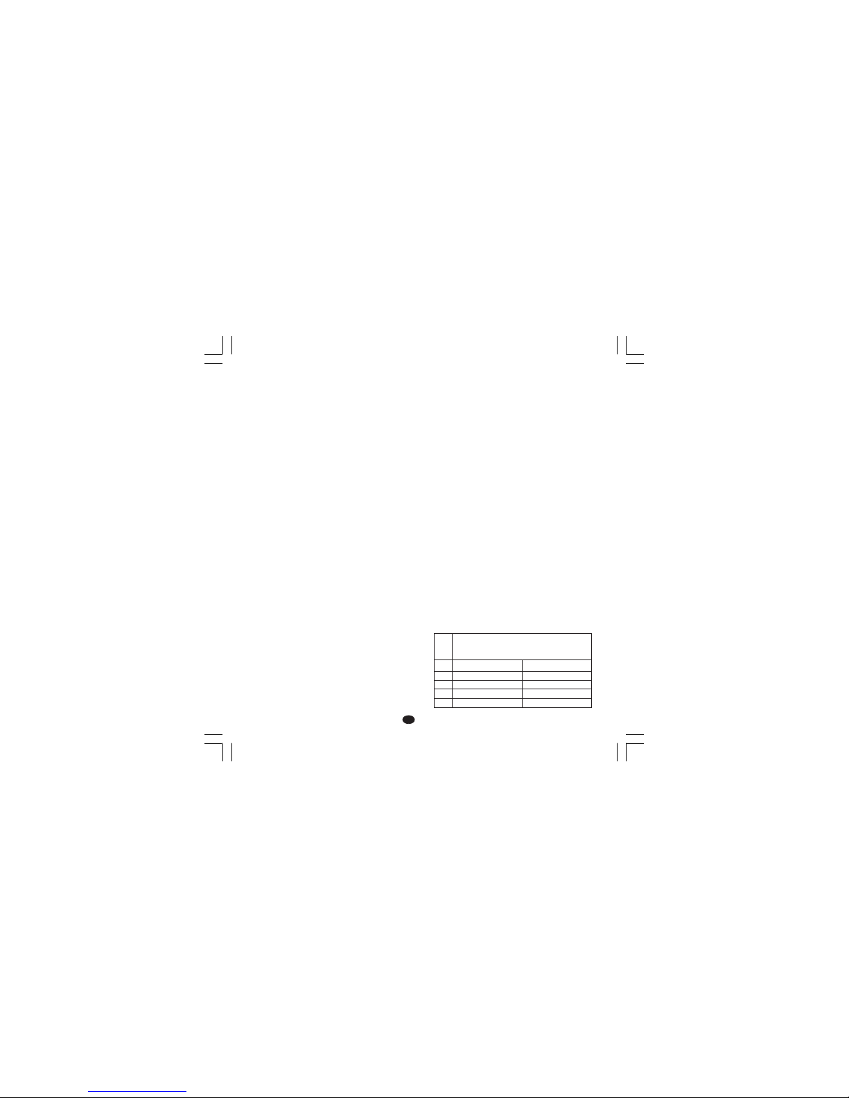
21
II
II
I
CARATTERISTICHE TECNICHECARATTERISTICHE TECNICHE
CARATTERISTICHE TECNICHECARATTERISTICHE TECNICHE
CARATTERISTICHE TECNICHE
SPECIFICHE TECNICHESPECIFICHE TECNICHE
SPECIFICHE TECNICHESPECIFICHE TECNICHE
SPECIFICHE TECNICHE
CustodiaCustodia
CustodiaCustodia
Custodia: PC-ABS di colore nero; grado di autoestinguenza: V-0 secondo UL 94.
Protezione frontaleProtezione frontale
Protezione frontaleProtezione frontale
Protezione frontale- Il prodotto è stato progettato
e verificato per garantire una protezione IP 65 (*) e
NEMA 4X per uso in luogo coperto.
(* le verifiche sono state eseguite in accordo gli
standard CEI 70-1 e NEMA 250-1991.
InstallazioneInstallazione
InstallazioneInstallazione
Installazione: Montaggio a pannello
Morsettiera posterioreMorsettiera posteriore
Morsettiera posterioreMorsettiera posteriore
Morsettiera posteriore:21 terminali a vite (vite
M3 per cavi da φ 0.25 a φ 2.5 mm
2
o da AWG 22
a AWG 14 ) con diagrammi di collegamento e
copri morsettiera di sicurezza.
DimensioniDimensioni
DimensioniDimensioni
Dimensioni: secondo DIN 43700 48 x 96 mm,
profondità 89 mm.
PesoPeso
PesoPeso
Peso: 600 g.
AlimentazioneAlimentazione
AlimentazioneAlimentazione
Alimentazione:
- da 100V a 240V c.a. 50/60Hz (-15% a + 10%
del valore nominale).
- 24 V c.c./c.a. (
+ 10 % del valore nominale).
AutoconsumoAutoconsumo
AutoconsumoAutoconsumo
Autoconsumo: 6 VA max.
Resistenza di isolamentoResistenza di isolamento
Resistenza di isolamentoResistenza di isolamento
Resistenza di isolamento: > 100 MΩ secondo
IEC 1010-1.
Rigidità dielettricaRigidità dielettrica
Rigidità dielettricaRigidità dielettrica
Rigidità dielettrica: 1500 V rms secondo
IEC 1010-1.
Intervallo di campionamento: Intervallo di campionamento:
Intervallo di campionamento: Intervallo di campionamento:
Intervallo di campionamento: 500 ms.
RisoluzioneRisoluzione
RisoluzioneRisoluzione
Risoluzione: 30000 conteggi.
PrecisionePrecisione
PrecisionePrecisione
Precisione:
+ 0,2% v.f.s. + 1 digit @ 25 °C di
temperatura ambiente.
Reiezione di modo comuneReiezione di modo comune
Reiezione di modo comuneReiezione di modo comune
Reiezione di modo comune: 120 dB a 50/60 Hz.
Reiezione di modo normale:Reiezione di modo normale:
Reiezione di modo normale:Reiezione di modo normale:
Reiezione di modo normale: 60 dB a 50/60 Hz.
Compatibilità elettromagnetica e normative diCompatibilità elettromagnetica e normative di
Compatibilità elettromagnetica e normative diCompatibilità elettromagnetica e normative di
Compatibilità elettromagnetica e normative di
sicurezzasicurezza
sicurezzasicurezza
sicurezza: Questo strumento è marcato CE e
pertanto è conforme alle direttive 89/336/EEC
(standard armonizzato di riferimento EN 50081-2
e EN 50082-2) ed alle direttive 73/23/EEC e
93/68/EEC (standard armonizzato di riferimento
EN 61010-1)
Categoria di installazioneCategoria di installazione
Categoria di installazioneCategoria di installazione
Categoria di installazione: II
Deriva termicaDeriva termica
Deriva termicaDeriva termica
Deriva termica: (CJ esclusa)
< 400 ppm/°C per ingresso da termocoppia T e
da RTD con scala -19.9/99.9°C.
< 200 ppm/°C per gli altri ingressi.
Temperatura di funzionamentoTemperatura di funzionamento
Temperatura di funzionamentoTemperatura di funzionamento
Temperatura di funzionamento: da 0 a 50 °C.
Temperatura di immagazzinamento:Temperatura di immagazzinamento:
Temperatura di immagazzinamento:Temperatura di immagazzinamento:
Temperatura di immagazzinamento:-20 a +70°C
UmiditàUmidità
UmiditàUmidità
Umidità: da 20 % a 85% RH, senza condensa.
ProtezioniProtezioni
ProtezioniProtezioni
Protezioni:
1) WATCH DOG circuito per il restart automatico.
2) DIP SWITCH per la protezione dei parametri di
configurazione e calibrazione.
INGRESSIINGRESSI
INGRESSIINGRESSI
INGRESSI
A) A)
A) A)
A)
TERMOCOPPIETERMOCOPPIE
TERMOCOPPIETERMOCOPPIE
TERMOCOPPIE
Tipo:Tipo:
Tipo:Tipo:
Tipo: L -J -K -T -N . °C/°F selezionabile.
Resistenza esternaResistenza esterna
Resistenza esternaResistenza esterna
Resistenza esterna: max. 100 Ω,con errore
massimo pari a 0,1% dell'ampiezza del campo
selezionato.
Burn outBurn out
Burn outBurn out
Burn out: segnalata come condizione di
overrange (standard). Tramite ponticelli è
possibile selezionare la condizione di underrange.
Giunto freddoGiunto freddo
Giunto freddoGiunto freddo
Giunto freddo: compensazione automatica da 0
a 50 °C.
Precisione giunto freddoPrecisione giunto freddo
Precisione giunto freddoPrecisione giunto freddo
Precisione giunto freddo: 0.1 °C/°C
Impedenza di ingressoImpedenza di ingresso
Impedenza di ingressoImpedenza di ingresso
Impedenza di ingresso: > 1 MΩ
CalibrazioneCalibrazione
CalibrazioneCalibrazione
Calibrazione: secondo IEC 584-1 e DIN 43710 -
1977.
TABELLA SCALE STANDARD
TipoTipo
TipoTipo
Tipo
TCTC
TCTC
TC
LL
LL
L
JJ
JJ
J
KK
KK
K
TT
TT
T
NN
NN
N
ScaleScale
ScaleScale
Scale
0 / + 800 °C
0 / + 800 °C
0 / + 999 °C
0 / + 400 °C
0 / + 999 °C
0 / + 999 °F
0 / + 999 °F
0 / + 999 °F
0 / + 752 °F
0 / + 999 °F
Nuovo-1 16/02/2005, 14.2421
Page 97

22
II
II
I
AZIONI DI CONTROLLOAZIONI DI CONTROLLO
AZIONI DI CONTROLLOAZIONI DI CONTROLLO
AZIONI DI CONTROLLO
Azione regolanteAzione regolante
Azione regolanteAzione regolante
Azione regolante: PID o SMART
Banda proporzionaleBanda proporzionale
Banda proporzionaleBanda proporzionale
Banda proporzionale: da 1.0 % (se si utilizza
una sola uscita regolante) oppure 1.5 % (se si
utilizzano due uscite regolanti) a 99.9 %
dell'ampiezza del campo di ingresso.
Impostando Pb = 0 la regolazione è del tipo ON/
OFF.
Isteresi Isteresi
Isteresi Isteresi
Isteresi (per controllo ON/OFF): da 0.1 % a 10.0
% dell'ampiezza del campo di ingresso.
Tempo integraleTempo integrale
Tempo integraleTempo integrale
Tempo integrale: da 10'' a 20' ; risoluzione 10
secondi. Impostando un valore superiore ai 20
minuti l'azione integrale risulterà esclusa.
Tempo derivativaTempo derivativa
Tempo derivativaTempo derivativa
Tempo derivativa: da 0 a 9' 59''.
Precarica dell'integrale:Precarica dell'integrale:
Precarica dell'integrale:Precarica dell'integrale:
Precarica dell'integrale:
- da 0 a 100 % per un'uscita regolante.
- da -100 a 100% per due uscite regolanti .
Tempo di ciclo dell'uscita principaleTempo di ciclo dell'uscita principale
Tempo di ciclo dell'uscita principaleTempo di ciclo dell'uscita principale
Tempo di ciclo dell'uscita principale: da 1 a 200
s.
Tempo di ciclo uscita raffreddamentoTempo di ciclo uscita raffreddamento
Tempo di ciclo uscita raffreddamentoTempo di ciclo uscita raffreddamento
Tempo di ciclo uscita raffreddamento: da 1 a
200 s.
Guadagno relativo dell'azione di raffredda-Guadagno relativo dell'azione di raffredda-
Guadagno relativo dell'azione di raffredda-Guadagno relativo dell'azione di raffredda-
Guadagno relativo dell'azione di raffreddamentomento
mentomento
mento: da 0.20 a 1.00 .
NOTA NOTA
NOTA NOTA
NOTA : è possibile limitare i parametri PB, TI, TD
e RCG quando la funzione SMART è abilitata.
Sovrapposizione/banda mortaSovrapposizione/banda morta
Sovrapposizione/banda mortaSovrapposizione/banda morta
Sovrapposizione/banda morta:
da - 20 % a 50 %
USCITE REGOLANTIUSCITE REGOLANTI
USCITE REGOLANTIUSCITE REGOLANTI
USCITE REGOLANTI
Tipo: Tipo:
Tipo: Tipo:
Tipo: tempo proporzionale.
Tempo di aggiornamentoTempo di aggiornamento
Tempo di aggiornamentoTempo di aggiornamento
Tempo di aggiornamento: 500 ms
Risoluzione dell'uscitaRisoluzione dell'uscita
Risoluzione dell'uscitaRisoluzione dell'uscita
Risoluzione dell'uscita: 1% dell'ampiezza del
campo.
AzioneAzione
AzioneAzione
Azione: diretta o inversa programmabile.
Limitatoe della potenza di uscitaLimitatoe della potenza di uscita
Limitatoe della potenza di uscitaLimitatoe della potenza di uscita
Limitatoe della potenza di uscita:
- per una uscita regolante: da 0.0 a 100.0 % .
- per due uscite regolanti: da -100.0 a +100.0%
B) RTDB) RTD
B) RTDB) RTD
B) RTD (
RR
RR
Resistance
TT
TT
Temperature
DD
DD
Detector)
TipoTipo
TipoTipo
Tipo: Pt 100 a 3 fili.
CorrenteCorrente
CorrenteCorrente
Corrente: 135 µA.
Resistenza di lineaResistenza di linea
Resistenza di lineaResistenza di linea
Resistenza di linea: Compensazione automatica
fino a 20 Ω/filo con :
- errore <
+0.1% dell'ampiezza del campo di
ingresso per il campo -19.9 a 99.9 °C.
- errore non misurabile per tutti gli altri campi.
Unità ingegneristicheUnità ingegneristiche
Unità ingegneristicheUnità ingegneristiche
Unità ingegneristiche: °C o °F programmabile.
Burn-outBurn-out
Burn-outBurn-out
Burn-out: a fondo scala.
NOTANOTA
NOTANOTA
NOTA: Uno speciale
controllo produce una segnalazione di
OVERRANGE quando la resistenza di ingresso è
inferiore a 15 Ω.
CalibrazioneCalibrazione
CalibrazioneCalibrazione
Calibrazione: secondo DIN 43760
TABELLA SCALE STANDARD
C) INGRESSO DAC) INGRESSO DA
C) INGRESSO DAC) INGRESSO DA
C) INGRESSO DA
TRASFORMATORE AMPEROMETRICOTRASFORMATORE AMPEROMETRICO
TRASFORMATORE AMPEROMETRICOTRASFORMATORE AMPEROMETRICO
TRASFORMATORE AMPEROMETRICO
Corrente di ingresso Corrente di ingresso
Corrente di ingresso Corrente di ingresso
Corrente di ingresso : 50 mA c.a.
Visualizzazione Visualizzazione
Visualizzazione Visualizzazione
Visualizzazione : selezionabile tra 10, 25, 50 oppure 100 A.
Risoluzione Risoluzione
Risoluzione Risoluzione
Risoluzione :
- per la portata 10 A : 0.1 A.
- Per le altre portate : 1 A.
Periodo attivoPeriodo attivo
Periodo attivoPeriodo attivo
Periodo attivo:
- per uscita a relè : NO o NC programmabile
- Per uscita comando SSR : livello logico 1
oppure 0 programmabile.
Minima durata del periodo attivoMinima durata del periodo attivo
Minima durata del periodo attivoMinima durata del periodo attivo
Minima durata del periodo attivo: 50 ms.
Tipo diTipo di
Tipo diTipo di
Tipo di
RTDRTD
RTDRTD
RTD
RTD Pt 100
RTD Pt 100
-199 - +500 °C
-19.9 - +99.9 °C
Campo di misuraCampo di misura
Campo di misuraCampo di misura
Campo di misura
-199 - +999 °F
-----
Nuovo-1 16/02/2005, 14.2422
Page 98

23
II
II
I
Questa funzione può essere operativa
all'accensione dello strumento per un tempo
programmabile (per evitare shock termici oppure
preriscaldare l'impianto).
USCITAUSCITA
USCITAUSCITA
USCITA
a) Uscita a relè con contatto SPDT;
Portata contatto 3A/250V c.a. su carico resistivo.
b) Tensione logica per SSR.
Stato logico 1:24V
+20% @1mA.
14V
+20% @20mA
Stato logico 0:<0.5V
Azione dell'uscitaAzione dell'uscita
Azione dell'uscitaAzione dell'uscita
Azione dell'uscita: diretta/inversa programmabile.
La selezione tra uscita a relè o tensione logica
viene effettuata tramite ponticello e parametro di
configurazione.
Uscita 2 - Raffreddamento o allarme 1Uscita 2 - Raffreddamento o allarme 1
Uscita 2 - Raffreddamento o allarme 1Uscita 2 - Raffreddamento o allarme 1
Uscita 2 - Raffreddamento o allarme 1
a) Uscita a relè con contatto SPST;
Portata contatto 2A/250V c.a. su carico
resistivo.
b) Tensione logica per SSR.
Stato logico 1:24V
+20% @1mA.
14V
+20% @20mA
Stato logico 0:<0.5V
La selezione tra uscita a relè o tensione logica
viene effettuata tramite ponticelli.
ALLARMIALLARMI
ALLARMIALLARMI
ALLARMI
Lo strumento può essere fornito di due allarmi
indipendenti.
L'allarme 1 è una funzione standard di questo
apparecchio mentre l'allarme 2 è opzionale.
Ogni allarme può essere configurato nei seguenti
modi :
Allarmi di processoAllarmi di processo
Allarmi di processoAllarmi di processo
Allarmi di processo:
Modo operativoModo operativo
Modo operativoModo operativo
Modo operativo: di massima o di minima.
SogliaSoglia
SogliaSoglia
Soglia: programmabile in unità ingegneristiche
all'interno del campo di ingresso (P3 - P2).
Allarmi di bandaAllarmi di banda
Allarmi di bandaAllarmi di banda
Allarmi di banda
Modo operativoModo operativo
Modo operativoModo operativo
Modo operativo: dentro o fuori banda.
SogliaSoglia
SogliaSoglia
Soglia: programmabile da 0 a 500 unità.
Allarmi di deviazioneAllarmi di deviazione
Allarmi di deviazioneAllarmi di deviazione
Allarmi di deviazione
Modo operativoModo operativo
Modo operativoModo operativo
Modo operativo: sotto o sopra il valore
programmato.
SogliaSoglia
SogliaSoglia
Soglia: programmabile da - 500 a +500 unità.
AzioneAzione
AzioneAzione
Azione: diretta o inversa programmabile
Risoluzione della sogliaRisoluzione della soglia
Risoluzione della sogliaRisoluzione della soglia
Risoluzione della soglia: 1 digit.
Isteresi di allarmeIsteresi di allarme
Isteresi di allarmeIsteresi di allarme
Isteresi di allarme: programmabile da 0.1 % a
10.0 % dell'ampiezza del campo di ingresso.
Riarmo allarmiRiarmo allarmi
Riarmo allarmiRiarmo allarmi
Riarmo allarmi: automatico o manuale
programmabile per ogni allarme.
Mascheratura allarmiMascheratura allarmi
Mascheratura allarmiMascheratura allarmi
Mascheratura allarmi: ogni allarme può essere
programmato con o senza la mascheratura.
Questa funzione consente di eliminare false
indicazioni di allarme all'accensione o dopo la
modifica del set point.
Indicazione di allarmeIndicazione di allarme
Indicazione di allarmeIndicazione di allarme
Indicazione di allarme: il LED AL1/COOL è acceso quando l'allarme è in condizione ON.
Il LED AL2/HBD si comporterà come indicato nella
tabella seguente
HBD AL2 LED
stato stato AL2/HBD
0 0 OFF
01 ON
1 0 lampeggia lentamente
1 1 lampeggia velocemente
Uscite di allarmeUscite di allarme
Uscite di allarmeUscite di allarme
Uscite di allarme:
1) allarme 1 : Uscita a relè con contatto SPST;
Portata contatto 3A/250V c.a. su carico
resistivo.
2) allarme 2 : Uscita a relè con contatto SPST;
Portata contatto 2A/250V c.a. su carico
resistivo.
NOTANOTA
NOTANOTA
NOTA: le funzioni Allarme 2 e HBD sono in
OR sull'uscita 2.
Nuovo-1 16/02/2005, 14.2423
Page 99

24
II
II
I
ALLARME DI MALFUNZIONAMENTO CARICOALLARME DI MALFUNZIONAMENTO CARICO
ALLARME DI MALFUNZIONAMENTO CARICOALLARME DI MALFUNZIONAMENTO CARICO
ALLARME DI MALFUNZIONAMENTO CARICO
Questo ingresso opzionale consente di misurare,
tramite trasformatore amperometrico, la corrente
circolante nel carico principale durante il periodo
attivo dell'uscita 1 e di generare una indicazione
di allarme qualora questo valore risultasse
inferiore ad una soglia programmabile (l'uscita di
allarme è in OR con l'allarme 2).
Risoluzione della sogliaRisoluzione della soglia
Risoluzione della sogliaRisoluzione della soglia
Risoluzione della soglia: 1 digit.
Isteresi di allarmeIsteresi di allarme
Isteresi di allarmeIsteresi di allarme
Isteresi di allarme: 1 % del campo selezionato.
Indicazione di allarmeIndicazione di allarme
Indicazione di allarmeIndicazione di allarme
Indicazione di allarme: Il LED ’AL2 HB"
lampeggia in condizione ON.
FUNZIONI SPECIALIFUNZIONI SPECIALI
FUNZIONI SPECIALIFUNZIONI SPECIALI
FUNZIONI SPECIALI
Inibizione del segnale di uscita.Inibizione del segnale di uscita.
Inibizione del segnale di uscita.Inibizione del segnale di uscita.
Inibizione del segnale di uscita.
Questa funzione consente di forzare a zero la
potenza delle uscite regolanti e di inibire
l'algoritmo di controllo e la funzione degli allarmi.
In questo modo si toglie potenza all'elemento
regolante mentre lo strumento opererà come un
semplice indicatore.
In questo modo è quindi possibile verificare il
comportamento della variabile anche quando il
carico è disattivato.
Quando viene riattivata l'azione regolante, lo
strumento si comporterà nel seguente modo:
- la componente integrale del segnale di uscita
verrà posta a zero,
- la funzione soft start e la mascheratura degli
allarmi verrranno riattivate.
LAMP TESTLAMP TEST
LAMP TESTLAMP TEST
LAMP TEST
questa funzione consente di verificare la
funzionalità del display
MANUTENZIONEMANUTENZIONE
MANUTENZIONEMANUTENZIONE
MANUTENZIONE
1) TOGLIERE TENSIONE ALL'APPARECCHIO
(alimentazione, uscite a relè, ecc),
2) Sfilare lo strumento dalla custodia
3) Facendo uso di un aspiratore o un getto di aria
compressa a bassa pressione (max. 3 kg/cm
2
)
rimuovere eventuali depositi di polvere e
sporcizia dalle ferritoie di ventilazione e dai
circuiti facendo attenzione a non danneggiare i
componenti.
4) Per pulire le parti esterne in plastica o gomma
usare solamente uno straccio pulito ed
inumidito con:
- alcool etilico (puro o denaturato) [C
2H5
OH]
-alcool isopropilico (puro o denaturato)
[(CH3)2CHOH]
- Acqua (H2O)
5) Controllare che non vi siano morsetti allentati
6) Prima di reinserire lo strumento nella sua custodia assicurarsi che l'apparecchio sia perfettamente asciutto.
7) Reinserire l'apparecchio e ridare tensione.
Nuovo-1 16/02/2005, 14.2424
Page 100

A. 1
DEFAULT PARAMETERSDEFAULT PARAMETERS
DEFAULT PARAMETERSDEFAULT PARAMETERS
DEFAULT PARAMETERS
DEFAULT OPERATIVE PARAMETERSDEFAULT OPERATIVE PARAMETERS
DEFAULT OPERATIVE PARAMETERSDEFAULT OPERATIVE PARAMETERS
DEFAULT OPERATIVE PARAMETERS
The control parameters can be loaded with
predetermined default values. These data are the
typical values loaded in the instrument prior to
shipment from factory. To load the default values
proceed as follows:
a ) The internal switch should be closed.
b) The SMART function should be disabled.
c) The upper display will show the process
variable while the lower display will show the
set point value or the current measure.
d) Held down pushbutton and press
pushbutton; the display will show:
e ) Within 10 seconds press or pushbutton.
The display will show:
g) Press FUNC pushbutton; the display will show:
This means that the loading procedure has been
initiated. After about 3 seconds the loading
procedure is terminated and the instrument
reverts to NORMAL DISPLAY mode.
The following is a list of the default operative
parameters loaded during the above procedure:
PARAMETER DEFAULT VALUE
SP = minimum range-value
n.rS = OFF
nnn =O FF
A1, A2 = minimum range-value for
process alarms
0 for deviation or band alarms
H1, H2 = 0.1 %
Pb = 4.0 %
hS =0.5 %
ti = 04.0 (4 minutes)
td = 1.00 (1 minute)
IP = 30 % for 1 control output
0 % for two control outputs
C = 20 seconds for relay output
2 seconds for SSR output
C2 = 10 seconds for P6 = AIr
4 seconds for P6 = OIL
2 seconds for P6 = H2O
rC = 1.00 for P6 = AIr
0.80 for P6 = OIL
0.40 for P6 = H2O
OLP = 0
rL = initial scale value
rH = full scale value
rP = infinite (step transfer)
OLH = 100 %
tOL =infinite
Hbd = 50 % of the full scale value.
O F FO F F
O F FO F F
O F F
D F L D F L
D F L D F L
D F L
O nO n
O nO n
O n
D F L D F L
D F L D F L
D F L
L. d t.L. d t.
L. d t.L. d t.
L. d t.
TMS-A-01.pmd 16/02/2005, 14.391
 Loading...