

Page 1
170.IU0.XKP.0D1 5/06
UU
USER MANUALUSER MANUAL
U
USER MANUAL
UU
USER MANUALUSER MANUAL
XKP-0-D1.pmd 25/05/2006, 11.271
PKPPKP
PKP
PKPPKP
MKPMKP
MKP
MKPMKP
Page 2

XKP-0-D1.pmd 25/05/2006, 11.272
Page 3

INDEXINDEX
INDEX
INDEXINDEX
MOUNTING REQUIREMENTS .................................................... 1
OUTLINE AND CUT OUT DIMENSIONS ..................................... 2
CONNECTION DIAGRAMS........................................................ 4
PRELIMINARY HARDWARE SETTINGS ................................... 19
SECURITY CODE SETTING MODE .......................................... 23
RUN TIME AND CONFIGURATION MODES ............................. 26
GENERAL NOTE ABOUT GRAPHIC SYMBOLS
USED FOR MNEMONIC CODE VISUALIZATION. ....... 26
KEYBOARD DESCRIPTION ......................................... 27
CONFIGURATION MODE .................................................... 28
MONITOR MODE .......................................................... 29
MODIFY MODE ............................................................. 30
RUN TIME MODE ................................................................. 68
PRELIMINARY .............................................................. 68
CONTROL PARAMETERS ............................................ 69
CONTROL PARAMETERS PROTECTION.................... 69
CONTROL PARAMETERS MODIFICA TION. ...................... 69
PROGRAMMER MODE .......................................................... 101
BARGRAPH DESCRIPTION ............................................104
INDICATORS ..................................................................105
DISPLAY FUNCTION DURING
PROGRAMMER MODE .............................................. 106
OUTPUT POWER OFF FUNCTION ............................ 109
XKP-0-D1.pmd 25/05/2006, 11.273
CLOCK CALENDAR .................................................... 110
OUT FAILURE DETECTION FUNCTION (OFD) ......... 111
SERIAL LINK ............................................................... 111
LAMP TEST ................................................................. 112
MANUAL MODE .......................................................... 112
DIRECT ACCESS TO THE SET POINT ...................... 113
GENERAL NOTES ABOUT PROGRAM EDITING ...... 114
EDIT MODE ................................................................. 114
SIMPLE PROGRAM MANAGEMENT ......................... 122
LINKED PROGRAM MANAGEMENT .......................... 125
HOW TO CHECK A PROGRAM .................................. 126
HOW TO RUN A PROGRAM (SIMPLE OR LINKED) .. 127
ACTIONS AVAILABLE DURING RUNNING MODE .... 128
CONTOLLER MODE .......................................................... 131
DISPLAY FUNCTION DURING
CONTROLLER MODE ................................................ 132
INDICATORS FUNCTION DURING
CONTROLLER MODE ................................................ 134
DIRECT ACCESS TO THE SET POINT ...................... 134
SMART FUNCTION ..................................................... 135
OUTPUT POWER OFF FUNCTION ............................ 136
ERROR MESSAGES .......................................................... 137
GENERAL INFORMATIONS............................................... 142
MAINTENANCE.................................................................. 151
DEFAULT PARAMETERS .................................................... A.1
CODING ............................................................................. A.15
Page 4

XKP-0-D1.pmd 25/05/2006, 11.274
Page 5
MOUNTING REQUIREMENTSMOUNTING REQUIREMENTS
MOUNTING REQUIREMENTS
MOUNTING REQUIREMENTSMOUNTING REQUIREMENTS
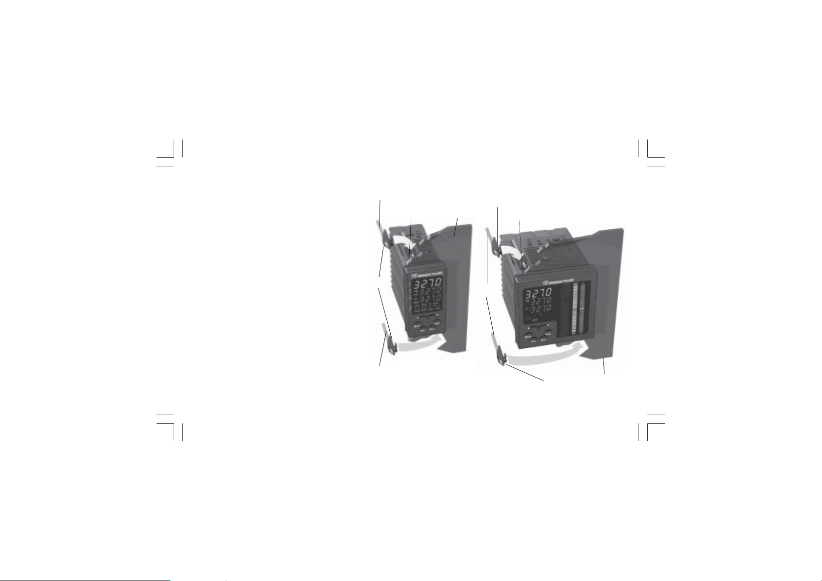
This instrument is intended for permanent installation,
for indoor use only, in an electrical panel which
encloses the rear housing, exposed terminals and
wiring on the back.
Select a location, for instrument mounting, where
minimum vibrations are present and the ambient
temperature is within 0 and 50 °C (32 and 122 °F).
The instrument can be mounted on a panel up to 15
mm thick with a cutout of 92 x 45 mm (PKP) or 92 x
92 mm (MKP).
For outline and cutout dimensions refer to Fig. 2.
The surface texture of the panel must be better
than 6,3 µm.
The instrument is shipped with rubber panel
gasket.
To assure the IP65 and NEMA 4 protection, insert
the panel gasket between the instrument and the
panel as shown in fig. 1.
While holding the instrument against the panel
proceed as follows:
1) insert the gasket in the instrument case;
2) insert the instrument in the panel cutout;
3) pushing the instrument against the panel;
4) insert the mounting brackets as shown in fig.1;
XKP-1-D1.pmd 25/05/2006, 11.281
Screw
brackets
Screw
5) with a screwdriver, turn the screws with a torque between
0.3 and 0.4 Nm.
bracket
Gasket
Panel
Gasket
Screws
Fig. 1
1
bracket
Panel
Page 6
OUTLINE AND CUT OUTOUTLINE AND CUT OUT
OUTLINE AND CUT OUT
OUTLINE AND CUT OUTOUTLINE AND CUT OUT
DIMENSIONSDIMENSIONS
DIMENSIONS
DIMENSIONSDIMENSIONS
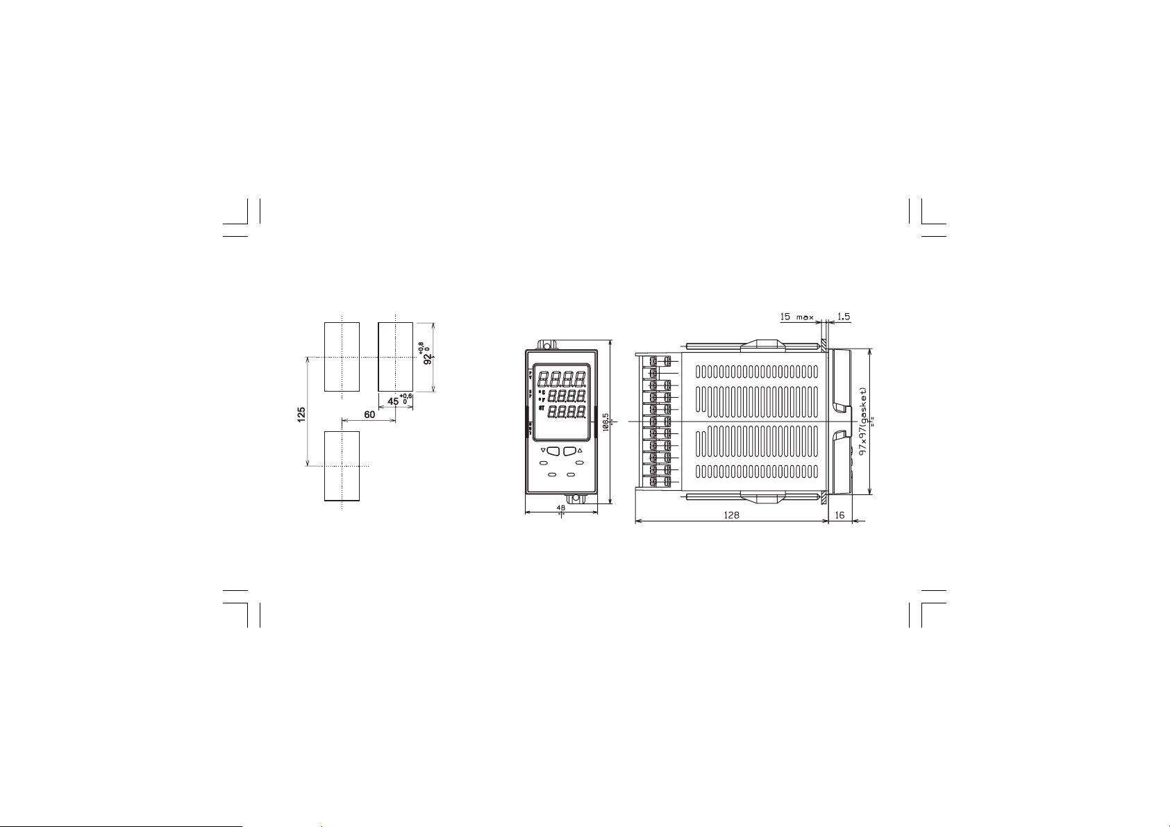
Fig. 2.A OUTLINE AND CUT-OUT DIMENSIONS FOR PKP MODEL
2
XKP-1-D1.pmd 25/05/2006, 11.282
Page 7
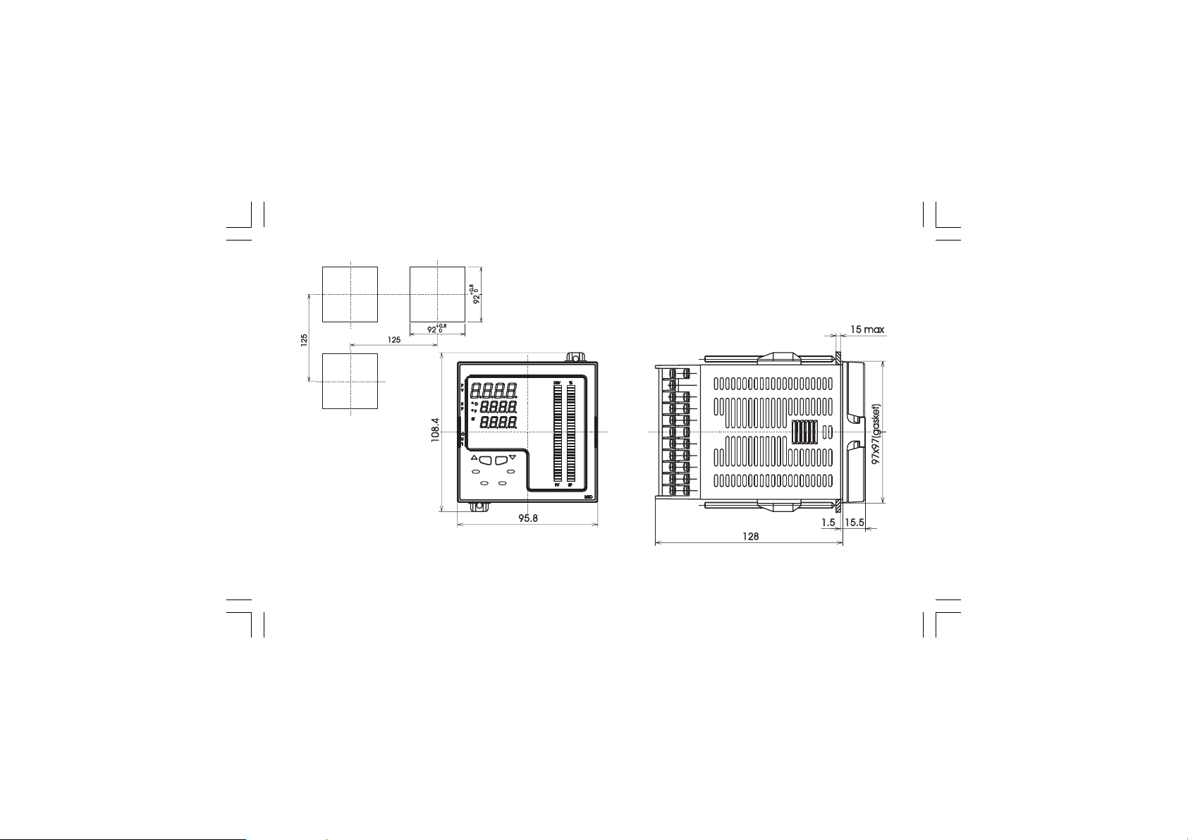
Fig. 2.B OUTLINE AND CUT-OUT DIMENSIONS FOR MKP MODEL
3
XKP-1-D1.pmd 25/05/2006, 11.283
Page 8
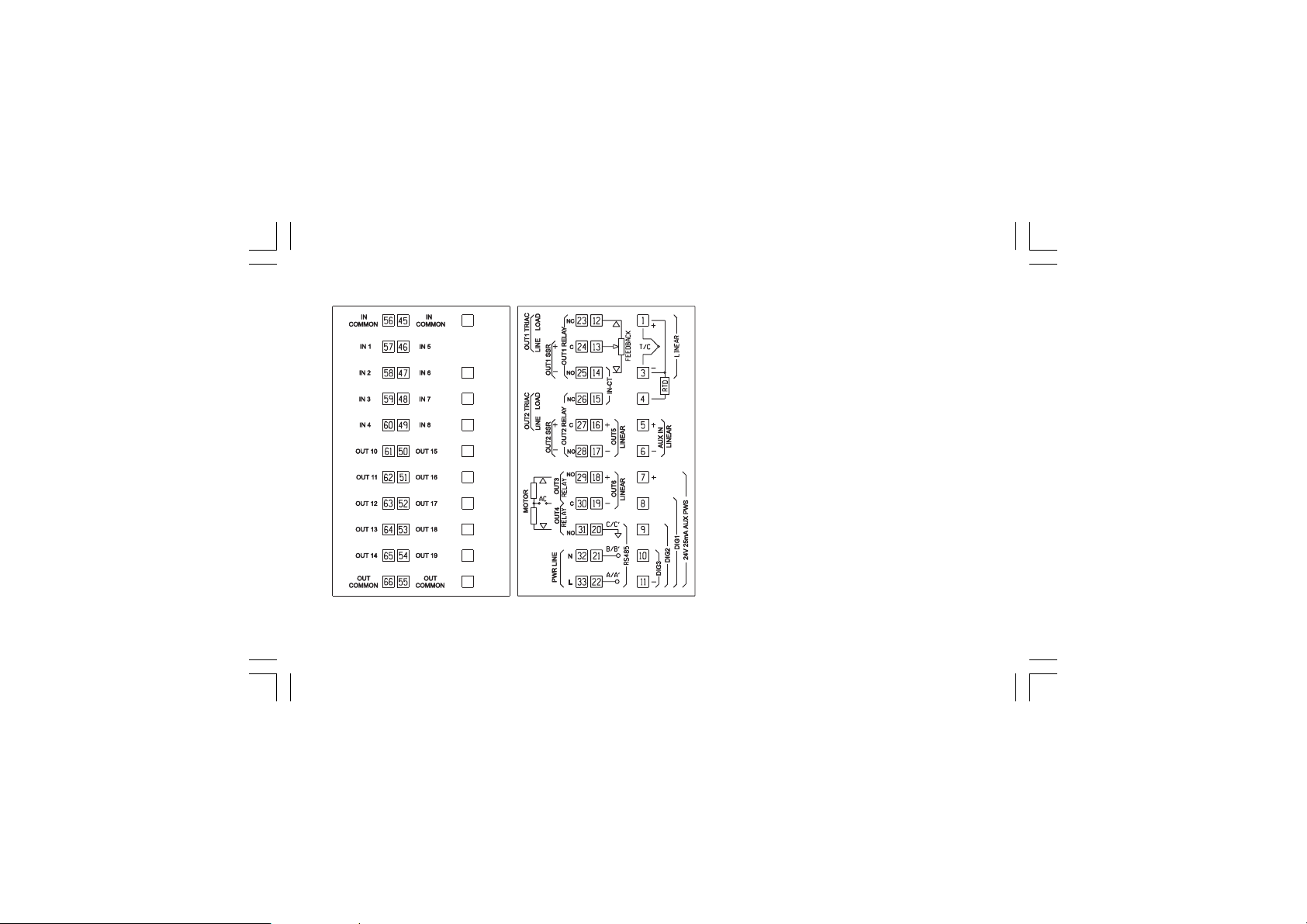
CONNECTION DIAGRAMSCONNECTION DIAGRAMS
CONNECTION DIAGRAMS
CONNECTION DIAGRAMSCONNECTION DIAGRAMS
Fig. 3 REAR TERMINAL BLOCK
XKP-1-D1.pmd 25/05/2006, 11.284
Connections are to be made with the instrument
housing installed in its proper location.
A) MEASURING INPUTSA) MEASURING INPUTS
A) MEASURING INPUTS
A) MEASURING INPUTSA) MEASURING INPUTS
NOTENOTE
NOTE: Any external component (like zener
NOTENOTE
barriers etc.) connected between sensor and input
terminals may cause errors in measurement due to
excessive and/or not balanced line resistance or
possible leakage currents.
4
Page 9
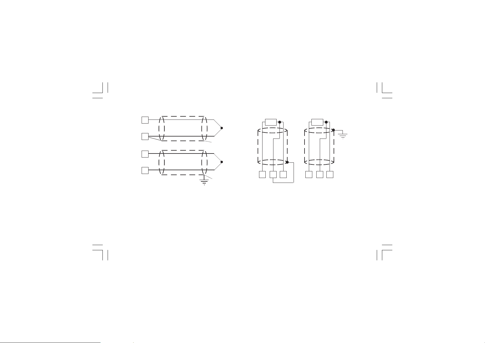
A.1) TC INPUTA.1) TC INPUT
A.1) TC INPUT
A.1) TC INPUTA.1) TC INPUT
1
+
_
3
1
+
_
3
Shield
Shield
A.2) RTD INPUTA.2) RTD INPUT
A.2) RTD INPUT
A.2) RTD INPUTA.2) RTD INPUT
RTD
4
3 4
RTD
1
3
1
Fig. 4 THERMOCOUPLE INPUT WIRING
NOTESNOTES
NOTES:
NOTESNOTES
1) Don’t run input wires together with power cables.
2) For TC wiring use proper compensating cable preferable
shielded.
3) When a shielded cable is used, it should be connected at
one point only.
XKP-1-D1.pmd 25/05/2006, 11.285
Fig. 5 RTD INPUT WIRING
NOTESNOTES
NOTES:
NOTESNOTES
1) Don’t run input wires together with power cables.
2) Pay attention to the line resistance; a high line resistance
may cause measurement errors.
3) When shielded cable is used, it should be grounded at one
side only to avoid ground loop currents.
4) The resistance of the 3 wires must be the same.
5
Page 10
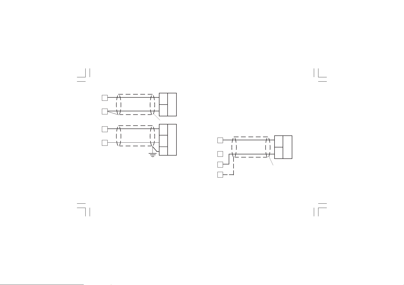
A.3) LINEAR INPUTA.3) LINEAR INPUT
A.3) LINEAR INPUT
A.3) LINEAR INPUTA.3) LINEAR INPUT
1
3
1
3
+
_
Shield
+
_
G
mA,
mV
or
V
mA
mV
or
V
3) When shielded cable is used, it should be grounded at one
side only to avoid ground loop currents.
4) The input impedance is equal to:
< 5 Ω for 20 mA input
> 1 MΩ for 60 mV input
> 200 kΩ for 5 V input
> 400 kΩ for 10 V input
A.4) 2, 3 AND 4-WIRE TRANSMITTER INPUTA.4) 2, 3 AND 4-WIRE TRANSMITTER INPUT
A.4) 2, 3 AND 4-WIRE TRANSMITTER INPUT
A.4) 2, 3 AND 4-WIRE TRANSMITTER INPUTA.4) 2, 3 AND 4-WIRE TRANSMITTER INPUT
1
3
_
TX
+
Fig. 6 mA, mV AND V INPUTS WIRING
NOTESNOTES
NOTES:
NOTESNOTES
1) Don’t run input wires together with power cables.
2) Pay attention to the line resistance; a high line resistance
may cause measurement errors.
XKP-1-D1.pmd 25/05/2006, 11.286
7
Shield
11
Fig. 7.A INPUTS WIRING FOR 2-WIRE TRANSMITTER
6
Page 11
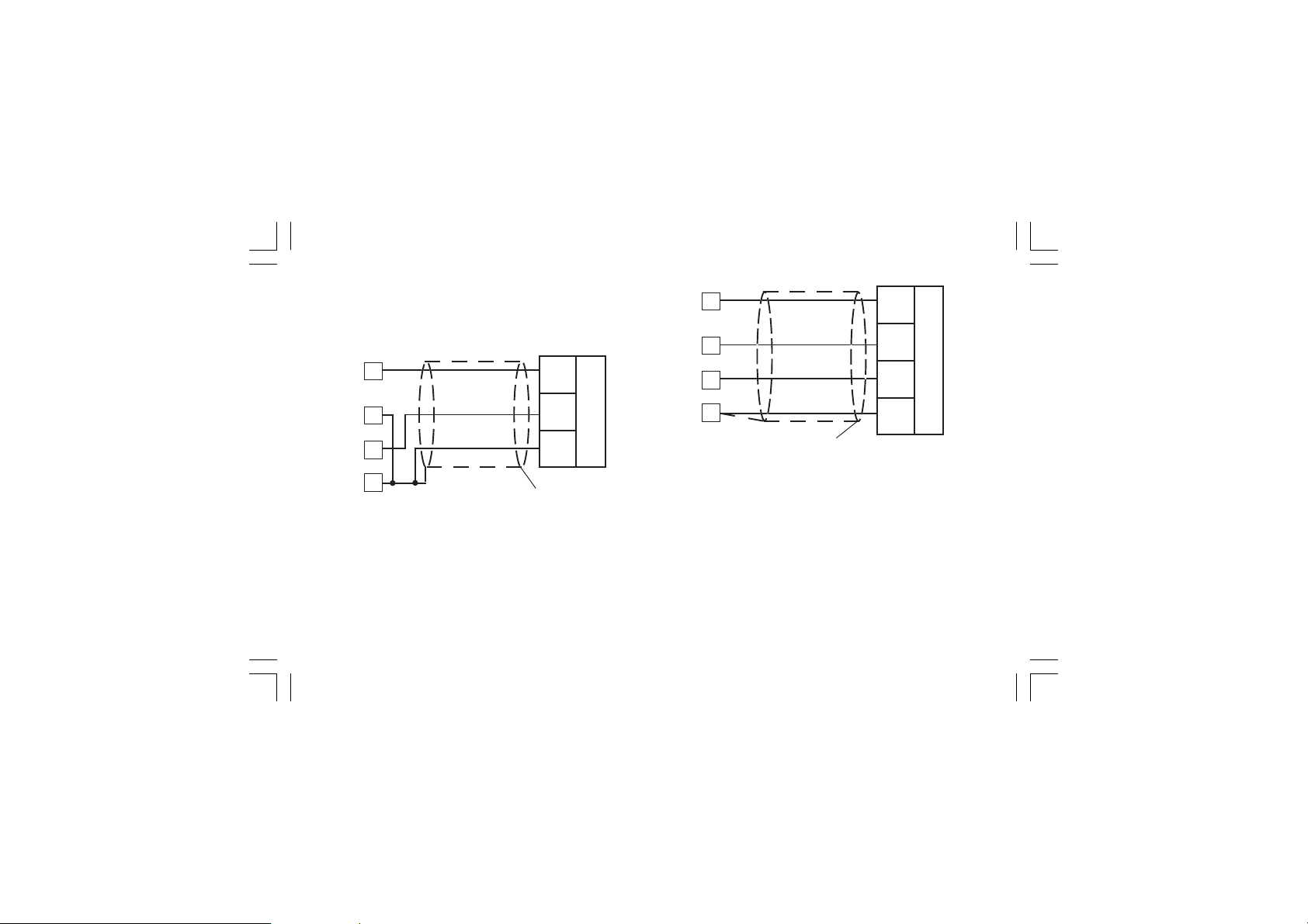
1
Out
+
Out
3
1
3
7
Out
PWR
+
GND
TX
7
11
Shield
_
PWR
+
PWR
_
TX
11
Fig. 7.B INPUTS WIRING FOR 3-WIRE TRANSMITTER
XKP-1-D1.pmd 25/05/2006, 11.287
Shield
Fig. 7.C INPUTS WIRING FOR 4-WIRE TRANSMITTER
NOTESNOTES
NOTES:
NOTESNOTES
1) Don’t run input wires together with power cables.
2) Pay attention to the line resistance; a high line resistance
may cause measurement errors.
3) When shielded cable is used, it should be grounded at one
side only to avoid ground loop currents.
4) The input impedance is lower than 5 Ω (20 mA input)
7
Page 12
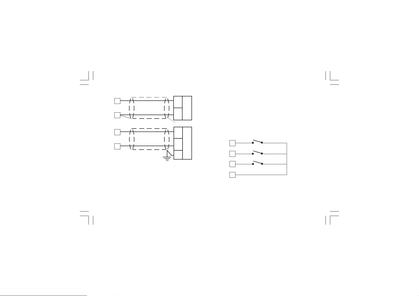
B) AUXILIARY INPUTB) AUXILIARY INPUT
B) AUXILIARY INPUT
B) AUXILIARY INPUTB) AUXILIARY INPUT
5
6
+
_
Shield
5
6
+
_
G
Fig. 8 AUXILIARY INPUT WIRING
NOTESNOTES
NOTES:
NOTESNOTES
1) This input is
reinforced insulation between instrument output and power
supply must be assured by the external instrument.
2) Don’t run input wires together with power cables.
3) Pay attention to the line resistance; a high line resistance
may cause measurement errors.
XKP-1-D1.pmd 25/05/2006, 11.288
not isolated not isolated
not isolated from measuring input. A double or
not isolated not isolated
mA
or
V
mA
or
V
4) When shielded cable is used, it should be grounded at one
side only to avoid ground loop currents.
5) The input impedance is equal to:
< 5 Ω for 20 mA input
> 200 kΩ for 5 V input
> 400 kΩ for 10 V input
C) LOGIC INPUTSC) LOGIC INPUTS
C) LOGIC INPUTS
C) LOGIC INPUTSC) LOGIC INPUTS
DIG. 1
8
DIG. 2
9
DIG. 3
10
11
Fig. 9.A - LOGIC INPUTS DIG 1, 2, 3 WIRING
8
Page 13
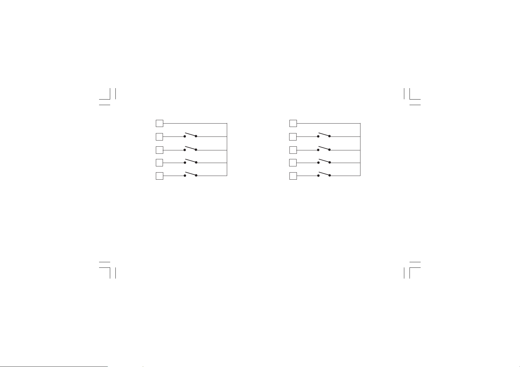
56
57
58
59
60
IN 1
IN 2
IN 3
IN 4
56
57
58
59
60
IN 5
IN 6
IN 7
IN 8
Fig. 9.B - LOGIC INPUTS IN 1, 2, 3 and 4 WIRING
XKP-1-D1.pmd 25/05/2006, 11.289
Fig. 9.C - LOGIC INPUTS IN 5, 6, 7 and 8 WIRING
NOTESNOTES
NOTES:
NOTESNOTES
1) Do not run logic input wiring together with power cables.
2) Use an external dry contact capable of switching 0.5 mA,
5 V DC.
3) The instrument needs 110 ms to recognize a contact status
variation.
4) The logic inputs are
A double or reinforced insulation between instrument input
and power line must be assured by the external element.
9
NOT NOT
NOT isolated by the measuring input.
NOT NOT
Page 14
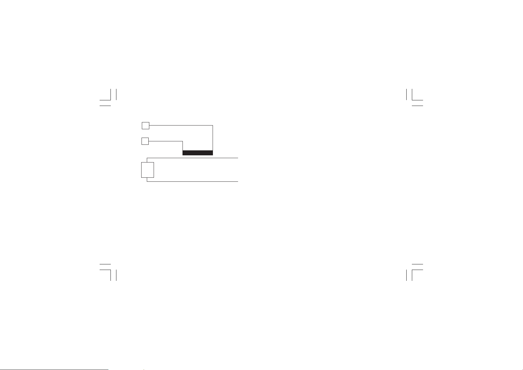
D) CURRENT TRANSFORMER INPUTD) CURRENT TRANSFORMER INPUT
D) CURRENT TRANSFORMER INPUT
D) CURRENT TRANSFORMER INPUTD) CURRENT TRANSFORMER INPUT
14
Current
15
Load
Fig. 10 CURRENT TRANSFORMER INPUT WIRING
This input allows you to measure and display the current
running in the load, driven by a time proportional control output,
during the ON and OFF periods of the output cycle time. By this
feature it is also available the "Output failure detection" function
(see page 110).
NOTESNOTES
NOTES:
NOTESNOTES
1) This input is
2) Do not run current transformer input wiring together with AC
power cables.
XKP-1-D1.pmd 25/05/2006, 11.2810
not isolated not isolated
not isolated from measuring input.
not isolated not isolated
transformer
3) The minimum active period to perform this measurement is
equal to 120 ms.
4) The input impedance is equal to 20 Ω.
10
Page 15
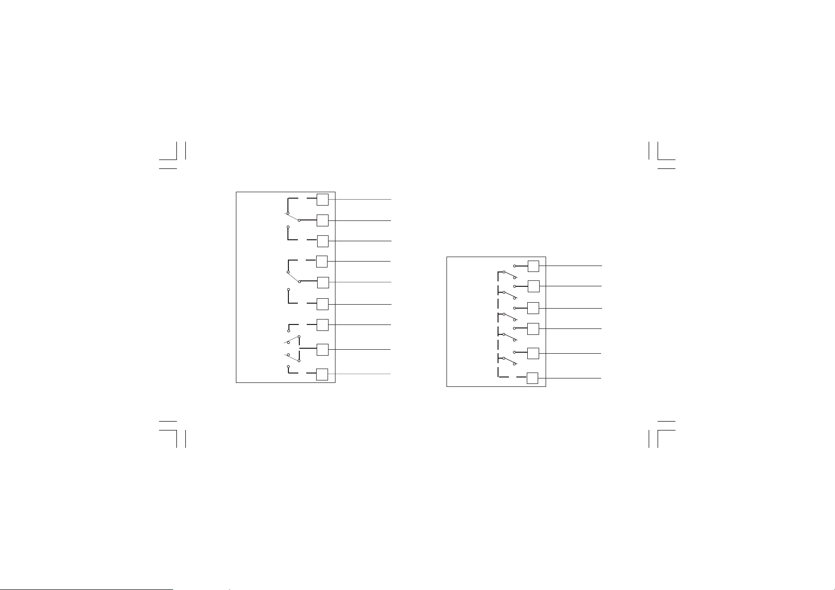
E.1) RELAY OUTPUTSE.1) RELAY OUTPUTS
E.1) RELAY OUTPUTS
E.1) RELAY OUTPUTSE.1) RELAY OUTPUTS
23
OUT 1
24
25
26
OUT 2
27
28
29
OUT 3
30
OUT 4
31
Fig. 11.A RELAY OUTPUTS 1,2,3 and 4 WIRING
XKP-1-D1.pmd 25/05/2006, 11.2811
NC
C
NO
NC
C
NO
NO - OUT 3
C - OUT 3/4
NO - OUT 4
The outputs from OUT 1 to OUT 4 are equipped with relays
having contact rating equal to 3A/250V AC on resistive load.
WARNINGWARNING
WARNING: When OUT 3 and 4 are used as independent relay
WARNINGWARNING
outputs the addition of the two currents must not exceed 3 A.
NO OUT 10
OUT 10
OUT 11
OUT 12
OUT 13
OUT 14
COMMON
Fig. 11.B RELAY OUTPUTS 10 to 14 WIRING
11
61
62
63
64
65
66
NO OUT 11
NO OUT 12
NO OUT 13
NO OUT 14
COMMON
Page 16
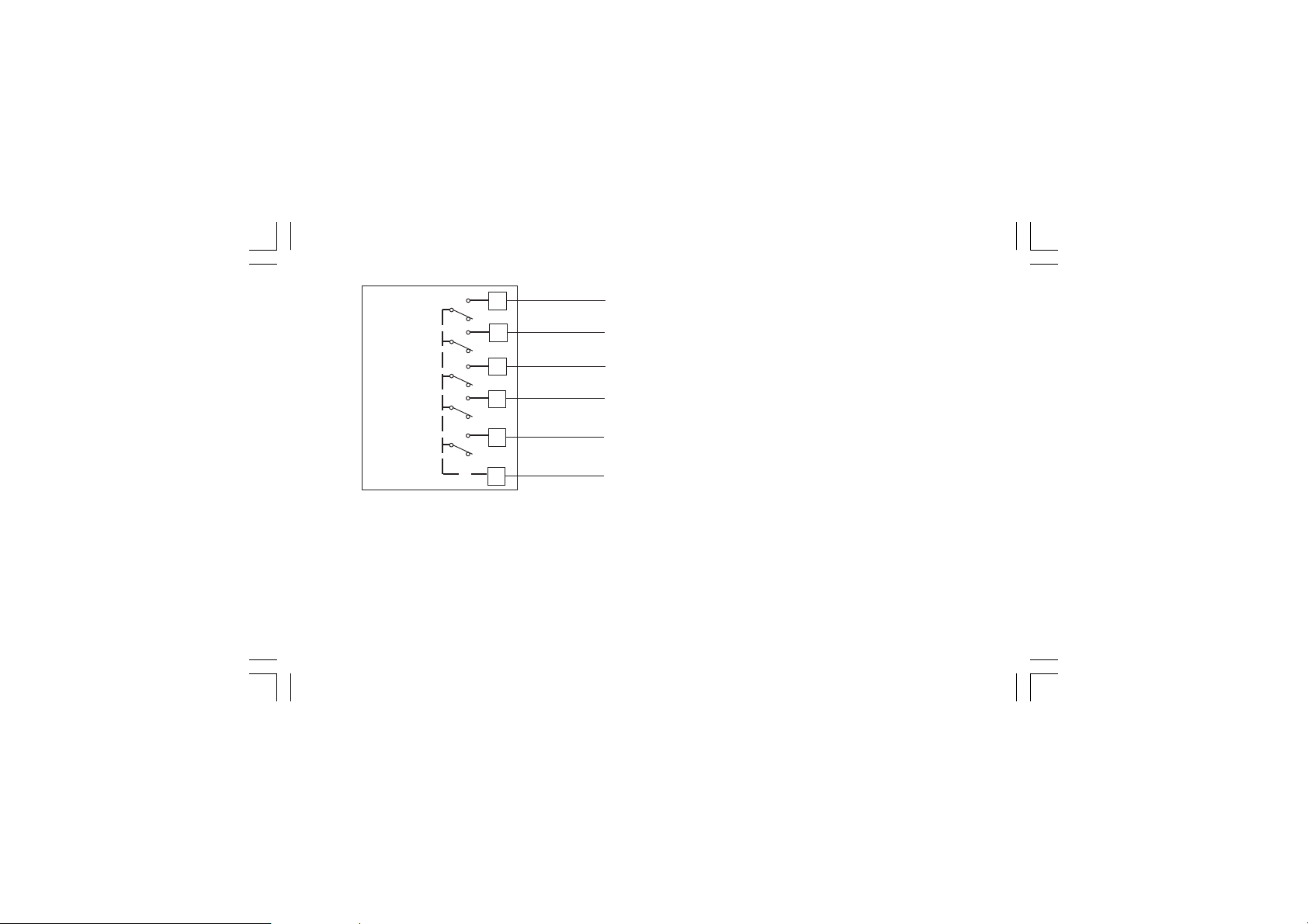
OUT 15
OUT 16
OUT 17
OUT 18
OUT 19
COMMON
50
51
52
53
54
55
NO OUT 15
NO OUT 16
NO OUT 17
NO OUT 18
NO OUT 19
COMMON
GENERAL NOTES ABOUT RELAY OUTPUT WIRINGGENERAL NOTES ABOUT RELAY OUTPUT WIRING
GENERAL NOTES ABOUT RELAY OUTPUT WIRING
GENERAL NOTES ABOUT RELAY OUTPUT WIRINGGENERAL NOTES ABOUT RELAY OUTPUT WIRING
1) To avoid electrical shock, connect power line at the end of
the wiring procedure.
2) For power connections use No 16 AWG or larger wires rated for
at last 75 °C.
3) Use copper conductors only.
4) Don’t run input wires together with power cables.
For all relay outputs, the number of operations is 1 x 10⁵ at
specified rating.
All relay contacts are protected by varistor against inductive load
with inductive component up to 0.5 A.
The following recommendations avoid serious problems which
may occur, when using relay output for driving inductive loads.
Fig. 11.C RELAY OUTPUTS 15 to 19 WIRING
The outputs from OUT 10 to 19 are equipped with relays having
contact rating equal to 0.5A/250V AC on resistive load.
XKP-1-D1.pmd 25/05/2006, 11.2812
INDUCTIVE LOADSINDUCTIVE LOADS
INDUCTIVE LOADS
INDUCTIVE LOADSINDUCTIVE LOADS
High voltage transients may occur switching inductive loads.
Through the internal contacts these transients may introduce
disturbances which can affect the performance of the
instrument.
For all the outputs, the internal protection (varistor) assures a
correct protection up to 0.5 A of inductive component.
12
Page 17
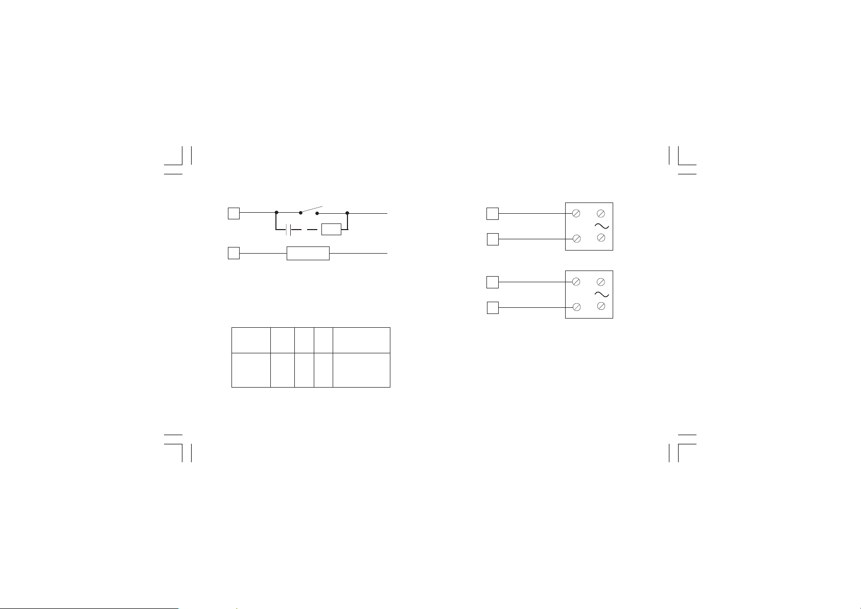
The same problem may occur when a switch is used in series
with the internal contacts as shown in Fig. 12.
C
R
LINE
LOAD
Fig. 12 EXTERNAL SWITCH IN SERIES WITH THE
INTERNAL CONTACT
In this case it is recommended to install an additional RC
network across the external contact as shown in Fig. 12
The value of capacitor (C) and resistor (R) are shown in the
following table.
C
LOAD
(mA)
<40 mA
<150 mA
<0.5 A
Anyway the cable involved in relay output wiring must be as far
away as possible from input or communication cables.
XKP-1-D1.pmd 25/05/2006, 11.2813
(µF)
0.047
0.1
0.33
R
(Ω)
100
22
47
P.
(W)
1/2
2
2
OPERATING
VOLTAGE
260 V AC
260 V AC
260 V AC
E.2) VOLTAGE OUTPUTS FOR SSR DRIVEE.2) VOLTAGE OUTPUTS FOR SSR DRIVE
E.2) VOLTAGE OUTPUTS FOR SSR DRIVE
E.2) VOLTAGE OUTPUTS FOR SSR DRIVEE.2) VOLTAGE OUTPUTS FOR SSR DRIVE
24
OUT 1
+
_
25
27
OUT 2
+
_
28
Fig. 13 SSR DRIVE OUTPUT WIRING
Logic level 0Logic level 0
Logic level 0: Vout < 0.5 V DC.
Logic level 0Logic level 0
Logic level 1Logic level 1
Logic level 1:
Logic level 1Logic level 1
14 V
+ 20 % @ 20 mA
24 V
+ 20 % @ 1 mA.
Maximum current = 20 mA.
13
+
__
_
__
SOLID STATE
RELAY
+
__
_
__
SOLID STATE
RELAY
Page 18
NOTENOTE
NOTE: This output is not isolated.
NOTENOTE
A double or reinforced insulation between instrument output
and power supply must be assured by the external solid state
relay.
E.3) TRIAC OUTPUTSE.3) TRIAC OUTPUTS
E.3) TRIAC OUTPUTS
E.3) TRIAC OUTPUTSE.3) TRIAC OUTPUTS
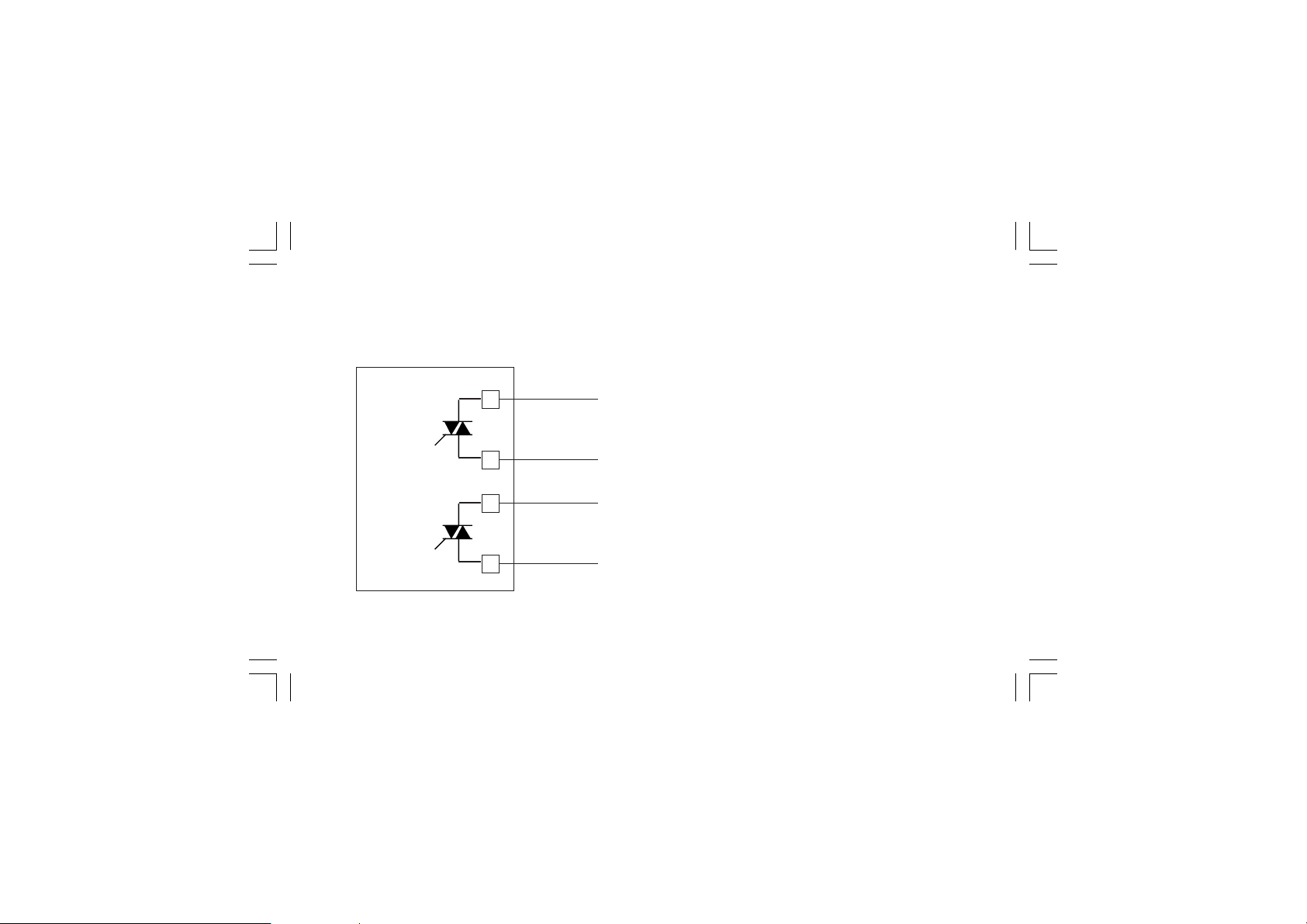
24
Line
OUT 1
23
Load
Switching modeSwitching mode
Switching mode: isolated zero crossing type.
Switching modeSwitching mode
Rated currentRated current
Rated current: from 50 mA to 1 A.
Rated currentRated current
Rated voltageRated voltage
Rated voltage: from 24 V
Rated voltageRated voltage
60Hz)
Load typeLoad type
Load type: resistive load only
Load typeLoad type
NOTESNOTES
NOTES 1 ) To avoid electrical shock, connect power line at
NOTESNOTES
the end of the wiring procedure.
2) For power connections use No 16 AWG or larger
wires rated for at last 75 °C.
3) Use copper conductors only.
4) Don’t run input wires together with power cables.
5) This output is not fuse protected. Please, provide it
externally using a fuse with a I2t equal to128.
to 240 V
RMS
-10 % +15 % (50/
RMS
27
OUT 2
26
Fig. 14 TRIAC OUTPUT WIRING
XKP-1-D1.pmd 25/05/2006, 11.2814
Line
Load
14
Page 19
E.4) SERVOMOTOR OUTPUTE.4) SERVOMOTOR OUTPUT
E.4) SERVOMOTOR OUTPUT
E.4) SERVOMOTOR OUTPUTE.4) SERVOMOTOR OUTPUT
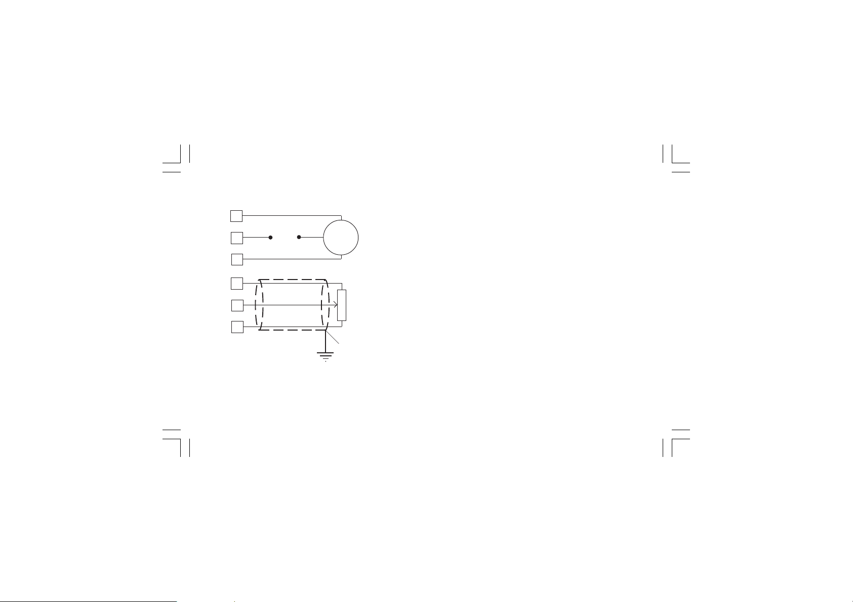
(Open the valve)
29
30
31
Power
line
(Close the valve)
12
13
14
Fig. 15 SERVOMOTOR OUTPUT WIRING
XKP-1-D1.pmd 25/05/2006, 11.2815
Servo-
motor
(Open)
(Close)
Shield
eter
Feedback
potentiom-
The two relay output must be interlocked (see chapter
"Preliminary hardware setting" paragraph "Out 3 and 4
selection").
NOTESNOTES
NOTES:
NOTESNOTES
1) Before connecting the instrument to the power line, make sure
that line voltage and the load current are in accordance with the
contact rating (3A/250V AC on resistive load).
2) To avoid electric shock, connect power line at the end of the
wiring procedure.
3) For servomotor connections use No 16 AWG or larger wires
rated for at last 75 °C.
4) Use copper conductors only.
5) Don’t run input wires together with power cables.
6) For feedback potentiometer, use shielded cable with the shield
connected to the earth at one point only.
7) The relay outputs are protected by varistors against
inductive load with inductive component up to 0.5 A.
15
Page 20
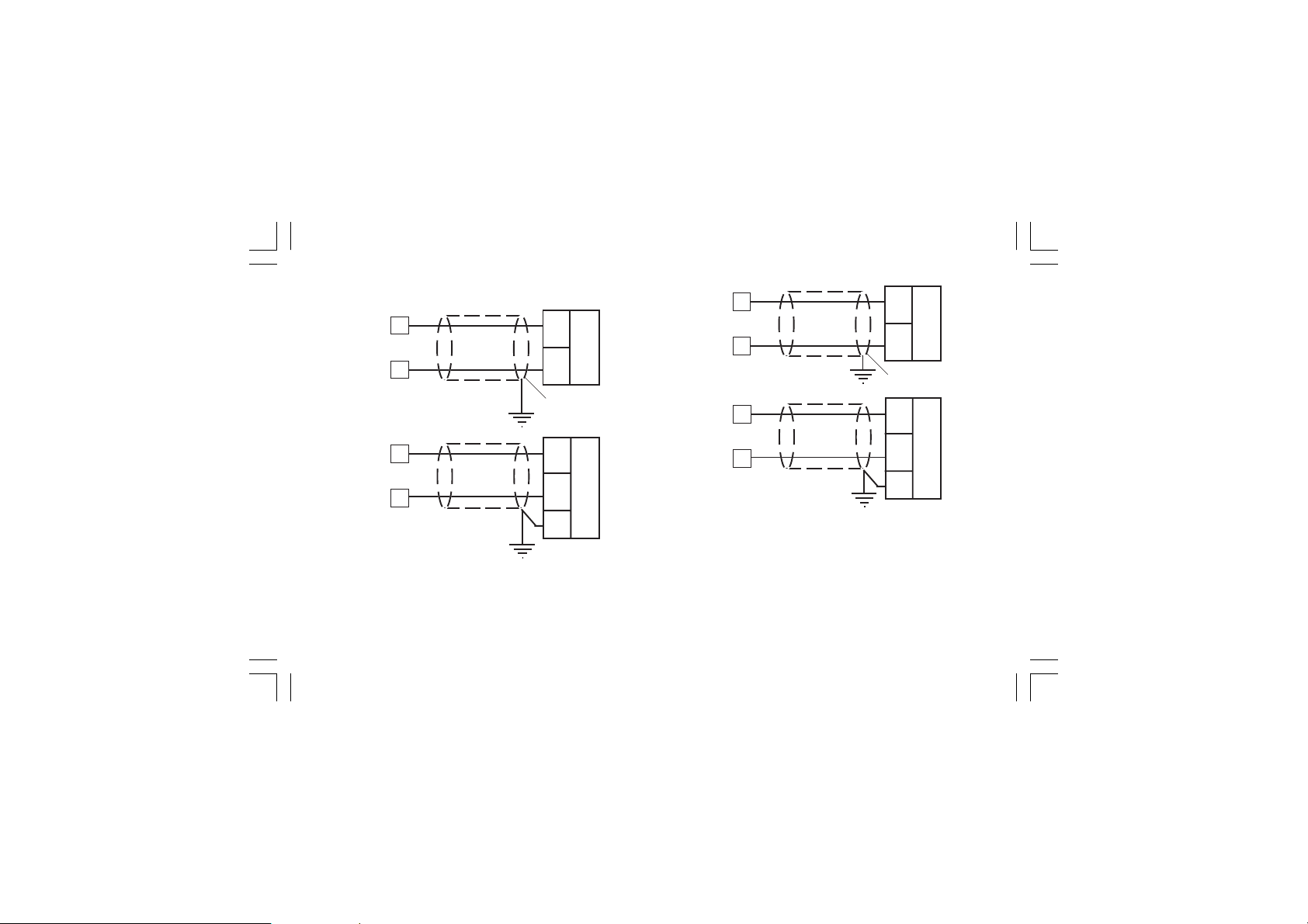
E.5) ANALOG OUTPUTSE.5) ANALOG OUTPUTS
E.5) ANALOG OUTPUTS
E.5) ANALOG OUTPUTSE.5) ANALOG OUTPUTS
+
16
OUT 5
_
17
+
16
OUT 5
_
17
+
_
Shield
+
_
20 mA20 mA
OUT 6
OUT 6
18
19
18
19
+
+
_
20 mA
_
Shield
+
_
+
_
20 mA
G
Fig. 16.A OUTPUT 5 WIRING
XKP-1-D1.pmd 25/05/2006, 11.2816
G
Fig. 16.B OUTPUT 6 WIRING
NOTENOTE
NOTE:
NOTENOTE
1) Do not run analog output wirings together with AC power
cables.
2) Out 5 and 6 are isolated outputs.
3) The maximum load is equal to 600 Ω.
16
Page 21
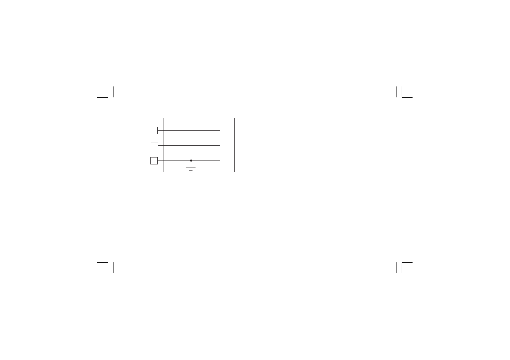
F) SERIAL INTERFACEF) SERIAL INTERFACE
F) SERIAL INTERFACE
F) SERIAL INTERFACEF) SERIAL INTERFACE
I
N
S
T
R
U
M
E
N
T
Fig. 17 - RS-485 WIRING
The cable length must not exceed 1.5 km at 9600 BAUD.
NOTESNOTES
NOTES:
NOTESNOTES
1) This is an isolated RS-485 serial interface.
2) The following report describes the signal sense of the
voltage appearing across the interconnection cable as
defined by EIA for RS-485.
a) The ” A ” terminal of the generator shall be negative with
respect to the ” B ” terminal for a binary 1 (MARK or OFF) state.
b) The ” A ” terminal of the generator shall be positive with
respect to the ” B ” terminal for a binary 0 (SPACE or ON).
XKP-1-D1.pmd 25/05/2006, 11.2817
22
21
20
A/A'
B/B'
COMMON
A'/A
B'/B
3) The EIA standard establishes that by RS-485 interface it is
possible to connect up to 30 devices with one remote master
unit.
M
A
S
T
E
R
The serial interface of these instruments is based on “High
input impedance” transceivers; this solution allows you to
connect up to 127 devices (based on the same transceiver
type) with one remote master unit.
17
Page 22
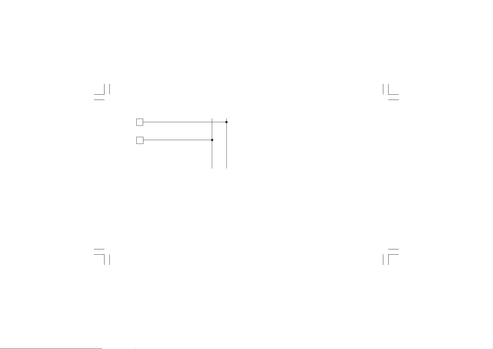
G) POWER LINE WIRINGG) POWER LINE WIRING
G) POWER LINE WIRING
G) POWER LINE WIRINGG) POWER LINE WIRING
N (L2)
32
POWER LINE 100 V to
240 V A.C (50/60Hz)
33
Fig. 18 POWER LINE WIRING
NOTESNOTES
NOTES:
NOTESNOTES
1) Before connecting the instrument to the power line, make sure
that line voltage corresponds to the description on the identification label.
2) To avoid electrical shock, connect power line at the end of the
wiring procedure.
3) For supply connections use No 16 AWG or larger wires rated for
at last 75 °C.
4) Use copper conductors only.
5) Don’t run input wires together with power cables.
XKP-1-D1.pmd 25/05/2006, 11.2818
or 24 V AC/DC
L (L1)
Line
Neutral
6) For 24 V DC the polarity is a not care condition.
7) The power supply input is fuse protected by a sub miniature
fuse rated T, 1A, 250 V.
When fuse is damaged, it is advisable to verify the power supply
circuit, so that it is necessary to send back the instrument to
your supplier.
8) The safety requirements for Permanently Connected
Equipment say:
- a switch or circuit-breaker shall be included in the building
installation;
- it shall be in close proximity to the equipment and within
easy reach of the operator;
- it shall be marked as the disconnecting device for the
equipment.
NOTENOTE
NOTE: a single switch or circuit-breaker can drive more than
NOTENOTE
one instrument.
9) When a neutral line is present please connect it to the 32
terminal.
18
Page 23
PRELIMINARY HARDWARE SETTINGSPRELIMINARY HARDWARE SETTINGS
PRELIMINARY HARDWARE SETTINGS
PRELIMINARY HARDWARE SETTINGSPRELIMINARY HARDWARE SETTINGS
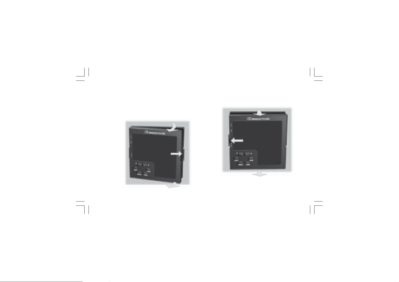
How to remove the instrument from its caseHow to remove the instrument from its case
How to remove the instrument from its case
How to remove the instrument from its caseHow to remove the instrument from its case
1) Switch off the instrument.
2) Push gently the lock A on the right.
3) While the lock A is maintained out, slide out the right side of
the instrument (see fig. 19.a)
B
A
4) Push gently the lock C on the left.
5) While the lock C is maintained out, slide out the instrument
(see fig. 19.b)
D
C
D
Fig. 19.a Fig. 19.b
XKP-1-D1.pmd 25/05/2006, 11.2819
B
19
Page 24
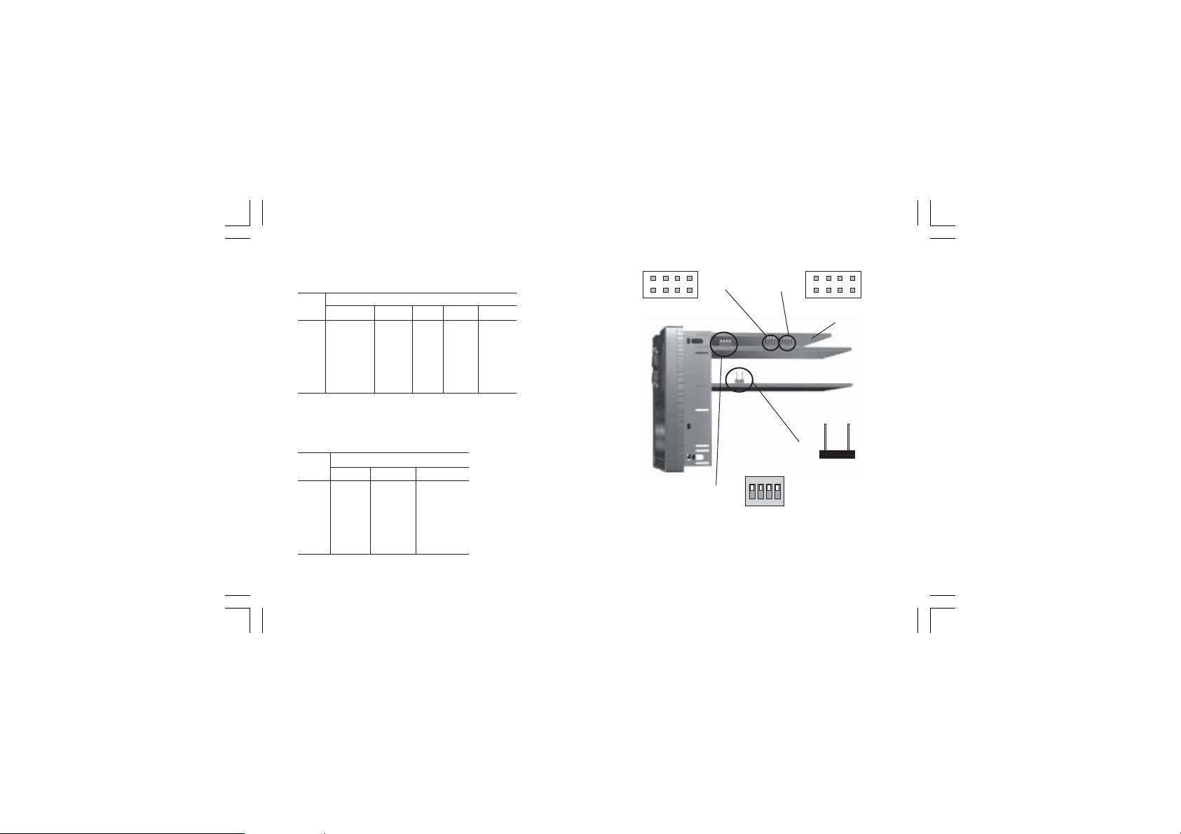
MAIN INPUT SELECTIONMAIN INPUT SELECTION
MAIN INPUT SELECTION
MAIN INPUT SELECTIONMAIN INPUT SELECTION
Set J103 (see fig. 20) according to the desired input type as
shown in the following table.
J103 INPUT TYPE
T/C, RTD 60 mV 5 V 10 V 20 mA
1-2 open open close open open
3-4 open open close close open
5-6 open open open open close
7-8 open open open open close
5-7 close close open close open
6-8 close close open open open
AUXILIARY INPUT SELECTION (option)AUXILIARY INPUT SELECTION (option)
AUXILIARY INPUT SELECTION (option)
AUXILIARY INPUT SELECTION (option)AUXILIARY INPUT SELECTION (option)
Set J102 (see fig. 20) according to the desired input type as
shown in the following table.
J102 INPUT TYPE
5 V 10 V 20 mA
1-2 close open open
3-4 close close open
5-6 open open close
7-8 open open close
5-7 open close open
6-8 open open open
XKP-1-D1.pmd 25/05/2006, 11.2820
20
Fig. 20
1 3 5 7
2 4 6 8
J102
V301
1 3 5 7
J103
2 4 6 8
CPU
card
J205
ON DIP
1 2 3 4
Page 25
OUTPUT 3 AND 4 SELECTIONOUTPUT 3 AND 4 SELECTION
OUTPUT 3 AND 4 SELECTION
OUTPUT 3 AND 4 SELECTIONOUTPUT 3 AND 4 SELECTION
Output 3 and 4 can be set as:
- 2 independent relay outputs
- 1 servomotor output with interlocked contact.
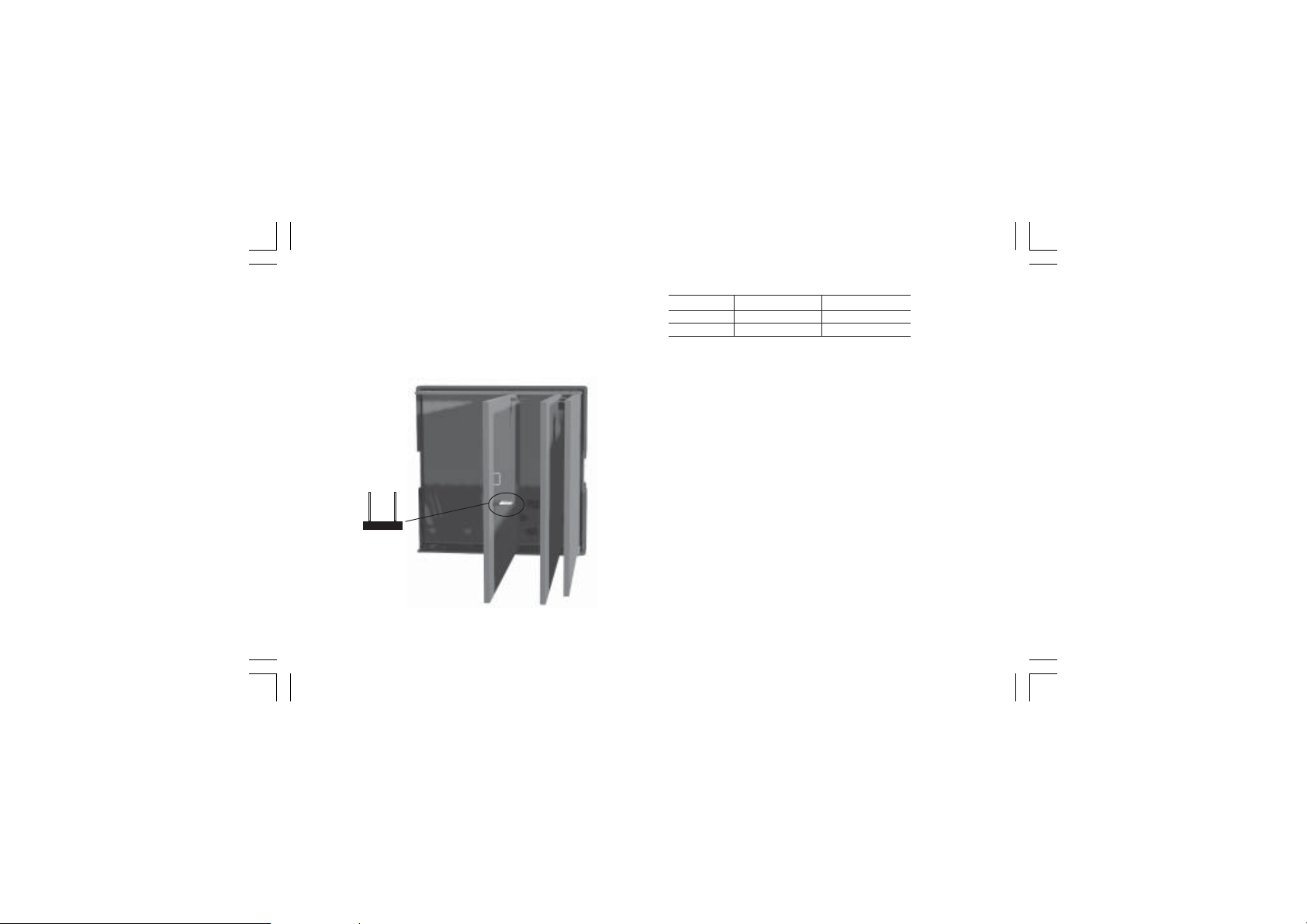
Set J204 (see fig. 21) and J205 (see fig. 20) according to the
desired output type as shown in the following table.
J204
Fig.21
XKP-1-D1.pmd 25/05/2006, 11.2821
Output J 204 J 205
Relay close open
Servo open close
NOTENOTE
NOTE: when the servomotor close loop or the servomotor open
NOTENOTE
loop with valve position indication outputs is required, it will be
necessary to set also V301 (see "IN CT/Feedback selection"
paragraph)
IN CT / FEEDBACK SELECTIONIN CT / FEEDBACK SELECTION
IN CT / FEEDBACK SELECTION
IN CT / FEEDBACK SELECTIONIN CT / FEEDBACK SELECTION
This instrument can use the "IN CT" input or the "Feedback"
input; the two inputs are not contemporarily.
The current transformer input allows you to measure and
display the current running in a load driven by a time proportional control output during the ON and OFF periods of the
output cycle time. By this feature it is also available the "Out
failure detection" function (see page 111).
The feedback input is used when the servomotor close loop or
the servomotor open loop with valve position indication outputs
is required.
21
Page 26
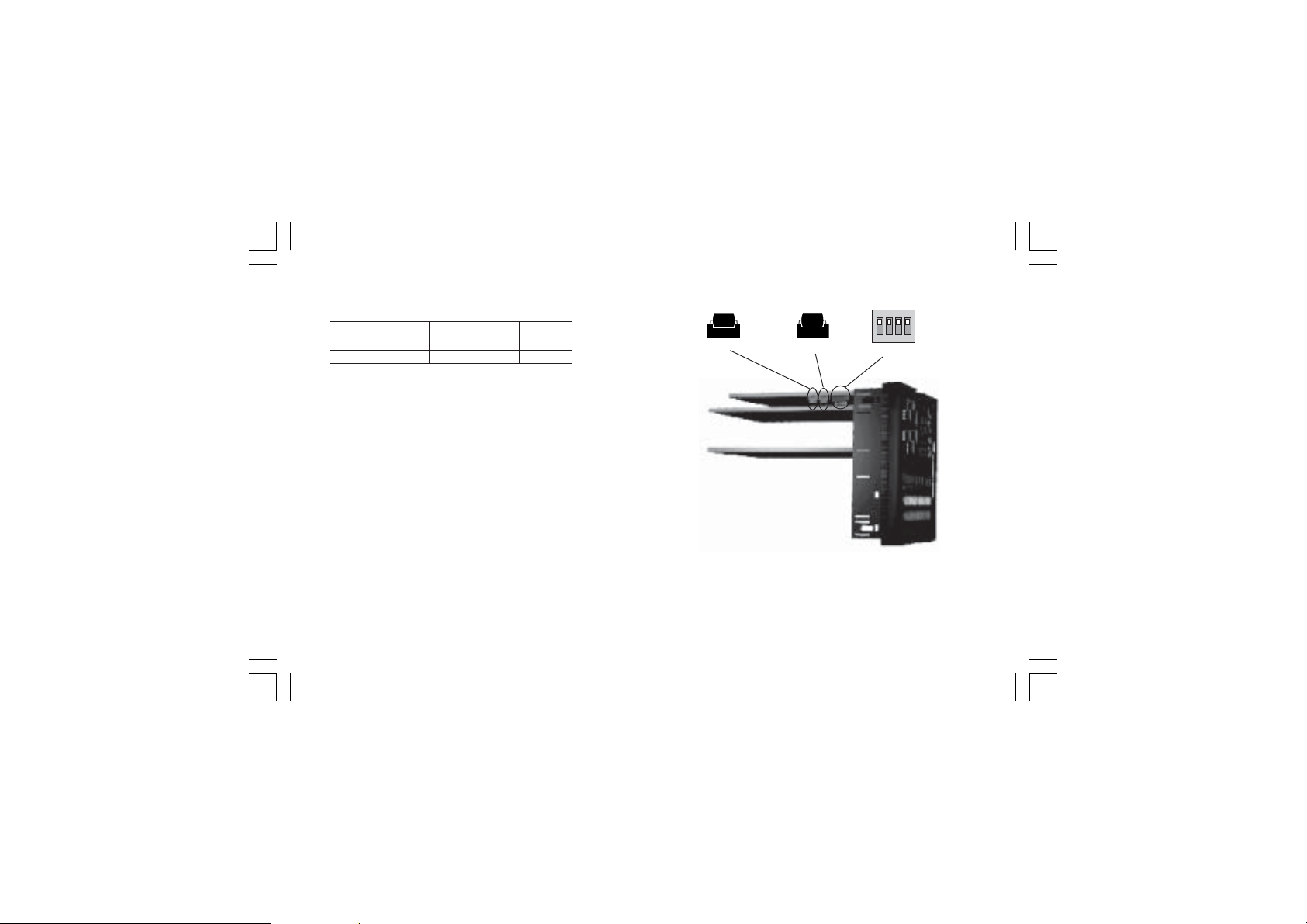
To select the desired input type, set V301 (see fig. 20) as
detailed in the following table:
Input V301.1 V301.2 V301.3 V301.4
IN CT ON OFF ON ON
Feedback OFF ON OF F O N
OPTION CHECKOPTION CHECK
OPTION CHECK
OPTION CHECKOPTION CHECK
This instrument can be supplied with several options.
Two integrated circuits (KY101 and KY103), located as shown
in fig. 22 and inserted in a socket, give you the possibility to
verify if your instrument is equipped with the desired option.
When KY101 is present the auxiliary input and the digital inputs
are present.
When KY103 is present the auxiliary power supply option is
present.
XKP-1-D1.pmd 25/05/2006, 11.2822
22
Fig. 22
KY101
KY103
ON DIP
1 2 3 4
V101
Page 27
Operative mode and Hardware lockOperative mode and Hardware lock
Operative mode and Hardware lock
Operative mode and Hardware lockOperative mode and Hardware lock
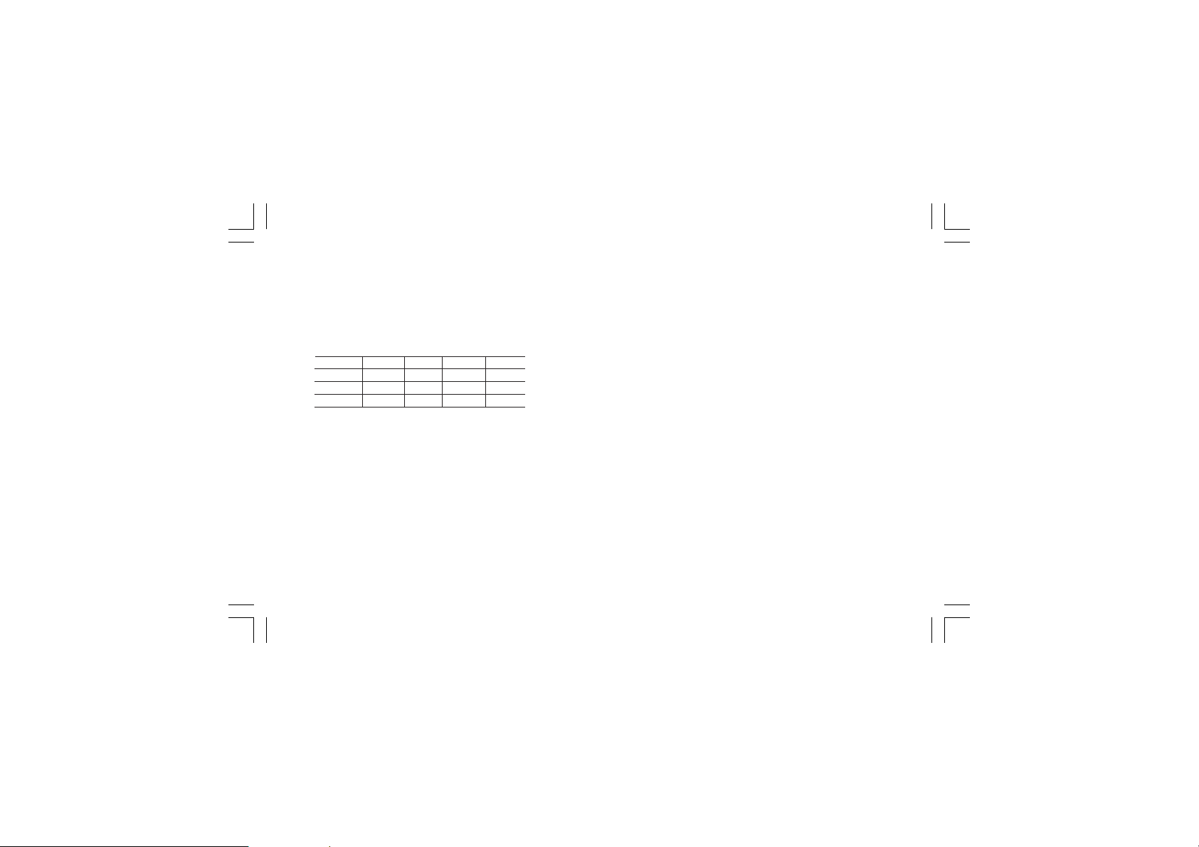
By V101 (see fig 22) it is possible to select one of the following
operative modes:
a) run time mode without configuration mode
b) run time and configuration modes
c) security code setting mode
Set V101 according to the following table:
Modes V101.1 V101.2 V101.3 V101.4
a OFF ON ON ON
b OFF ON OFF ON
c OFF ON OFF OFF
All the others switch combinations are reserved.
XKP-1-D1.pmd 25/05/2006, 11.2823
SECURITY CODE SETTING MODESECURITY CODE SETTING MODE
SECURITY CODE SETTING MODE
SECURITY CODE SETTING MODESECURITY CODE SETTING MODE
General notesGeneral notes
General notes
General notesGeneral notes
The instrument parameters are divided in two families and each
family is divided in groups.
- The first family encompasses all the run time parameters.
- The second family comprises all the configuration parameters.
A specific security code enables the parameter modification of
each family.
For run time parameters, it is possible to select which groups of
them will be protected by the security code and in this case, it
is necessary to set the run time security code before to modify
one or more parameters of a protected group.
The configuration security code protects all configuration
parameters and it will be necessary to set the configuration
security code before to start the configuration parameters
modification.
For configuration parameters an hardware lock is also
available.
23
Page 28
Security code settingSecurity code setting
Security code setting:
Security code settingSecurity code setting
1) Remove the instrument from its case.
2) Set the internal dip switch V101 as follows:
- V101.1 = OFF - V101.2 = ON
- V101.3 = OFF - V101.4 = OFF
3) Re-insert the instrument.
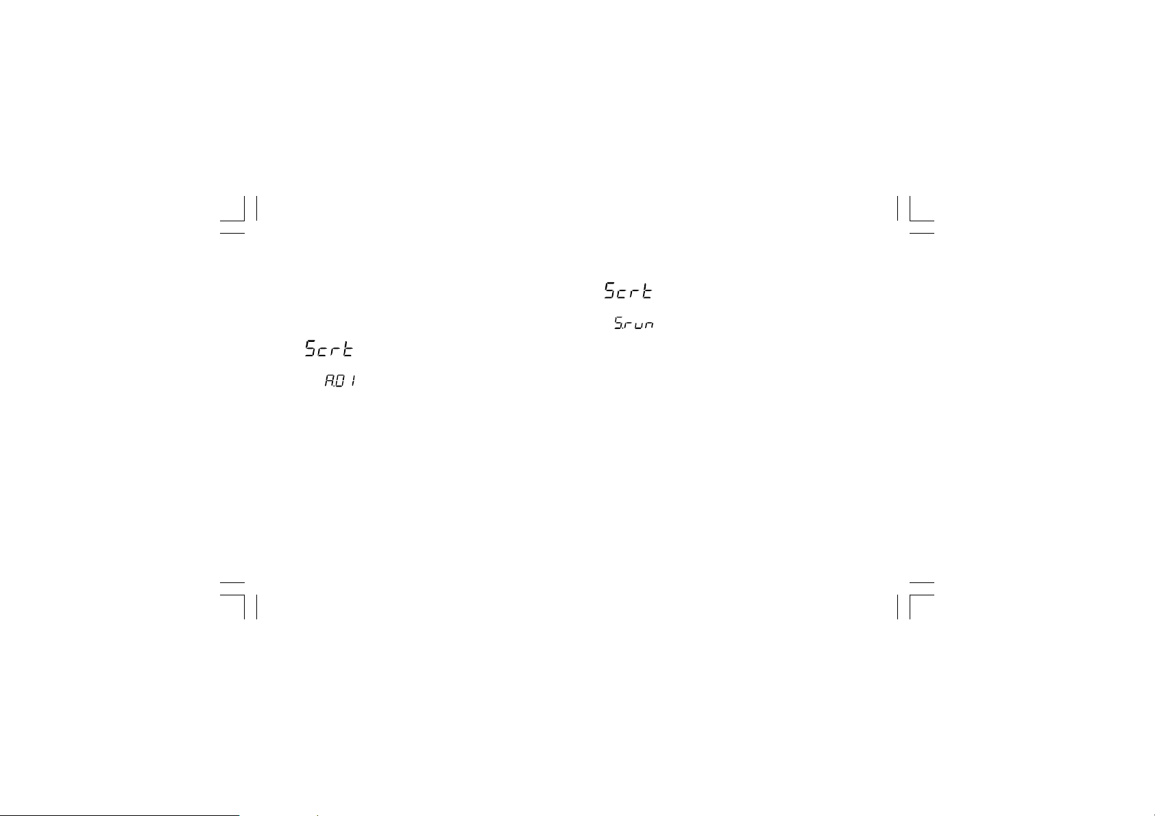
4) Switch on the instrument. The display will show:
The upper display shows that the security code setting mode
is selected while the lower display shows the firmware
version.
5) Push the FUNC pushbutton.
XKP-1-D1.pmd 25/05/2006, 11.2824
Run time security codeRun time security code
Run time security code
Run time security codeRun time security code
The display will show:
NoteNote
Note: the middle display shows the current status of the run
NoteNote
time security code ("0", "1" or "On").
By and push-button, set "S.run" parameter as follows:
0 No protection (it is ever possible to modify all run
time parameters);
1 ever protected (it is never possible to modify a run
time parameter);
from 2 to 250 security code for run time parameter
protection.
NOTESNOTES
NOTES:
NOTESNOTES
1) The selected value of a security code cannot be displayed
anymore and, coming back to the "S.run" parameter, the
display will show :
- "On" when "S.run" is different from 0 or 1
- "0" when "S.run" is equal to 0
- "1" when "S.run" is equal to 1.
When the security code is forgotten, a new value can be set.
2) When "S.run" is different from 0 or 1, the "run time default "
24
Page 29

and the "run time hidden" groups are ever protected by
security code.
Run time groups protected by security codeRun time groups protected by security code
Run time groups protected by security code
Run time groups protected by security codeRun time groups protected by security code
The display will show:
By this parameter it is possible to set if the run time group 2 will
be protected or not by the run time security code.
By and push-button, set "Gr2" parameter as follows:
nO No protection (it is always possible to modify run time
group 2 parameters)
Ye s the run time group 1 parameter modification will be
protected by security code.
Push the FUNC push-button; the instrument memorizes the
new setting and goes to the next parameter.
NOTESNOTES
NOTES:1)This selection may be carried out only if a run time
NOTESNOTES
security code has been set (from 2 to 250).
2) The above described selection may be repeated for
all groups of the run time mode.
XKP-1-D1.pmd 25/05/2006, 11.2825
Configuration security codeConfiguration security code
Configuration security code
Configuration security codeConfiguration security code
The display will show:
NoteNote
Note: the middle display shows the current status of the
NoteNote
configuration security code ("0", "1" or "On").
By and push-button, set "S.CnF" parameter as follows:
0 No protection (it is ever possible to modify all
configuration parameters);
1 ever protected (it is never possible to modify a
configuration parameter);
from 2 to 250 security code for configuration parameter
protection.
NOTENOTE
NOTE: the selected value of a security code cannot be
NOTENOTE
displayed anymore and, coming back on the "S.CnF"
parameter, the display will show "On" when "S.CnF" is
different from 0 or 1, "0" when "S.CnF" is equal to 0,
"1" when "S.CnF" is equal to 1.
When the security code is forgotten, a new value can
be set.
25
Page 30

NOTENOTE
NOTE: at the end of the security code setting procedure, set
NOTENOTE
V101 according to the desired operative mode (see
"Operative mode and hardware lock" paragraph).
XKP-1-D1.pmd 25/05/2006, 11.2826
RUN TIME AND CONFIGURATION MODESRUN TIME AND CONFIGURATION MODES
RUN TIME AND CONFIGURATION MODES
RUN TIME AND CONFIGURATION MODESRUN TIME AND CONFIGURATION MODES
The hardware selection described in "Operative mode and
hardware lock" paragraph allows you to start one of the
following operative modes:
- configuration mode.
- run time mode
The run time mode can be divided as follows:
- Run time mode as controller
- Run time mode as programmer
At power up, the instrument starts in the same mode (configuration or run time) it was prior to the power OFF.
General note about graphic symbols used for mnemonicGeneral note about graphic symbols used for mnemonic
General note about graphic symbols used for mnemonic
General note about graphic symbols used for mnemonicGeneral note about graphic symbols used for mnemonic
code visualization.code visualization.
code visualization.
code visualization.code visualization.
The instrument displays some characters with special symbols.
The following table shows the correspondence between the
symbols and the characters
symbol character symbol character
"
"k ""W
"m ""Z
"
" "V ""J
26
Page 31

Keyboard descriptionKeyboard description
Keyboard description
Keyboard descriptionKeyboard description
MENU = is used to select a parameter group
FUNC = when the instrument is in "normal display mode" it
changes the indication on the lower display (see
"display function").
During parameter modification, it allows you to
memorize the new value of the selected parameter
and go to the next parameter (increasing order).
MAN = when the instrument is in "normal display mode",
pushing MAN push-button for more than 1 s, it is
possible to enable or disable the manual function.
During parameter modification, it allows you to
scroll back the parameters and groups without
memorizing the new setting.
= During parameter modification, it allows you to
increase the value of the selected parameter
During MANUAL mode, it allows you to increase
the output value.
During program execution with the instrument in
HOLD status, it allows you to shift forward the
program with a speed 60 time faster than normal.
XKP-1-D1.pmd 25/05/2006, 11.2827
= During parameter modification, it allows you to
decrease the value of the selected parameter
During MANUAL mode, it allows to decrease the
output value.
During program execution with the instrument in
HOLD status, it allows you to shift backward the
program with a speed 60 time faster than normal.
RUN = allows:
- to rapidly select the program to execute.
- to start program execution,
- to toggle from RUN to HOLD mode or viceversa
(pushing for more than 3 s and less than 10 s) or
- to ABORT program execution (pushing for more
than 10 s).
RUN + = during program editing are used to add a program
segment (see paragraph "How to edit a program")
RUN + = during program editing are used to delete a
program segment (see paragraph "How to edit a
program")
RUN + MENU = during program editing are used to jump to
the first parameter of the next segment (see
paragraph "How to edit a program")
RUN + MAN = during program editing are used to check the
selected program (see paragraph "How to check a
program")
27
Page 32

+MENU= are used to start the lamp test function (see
+FUNC or +FUNC
+MAN or +MAN
NOTESNOTES
NOTES:
NOTESNOTES
1) All the actions explained above which require the pressure of
2) A 10 or 30 seconds time out (see "t.out" [C.I10]) can be
XKP-1-D1.pmd 25/05/2006, 11.2828
paragraph "Lamp test")
During parameter modification they allow you to
increase/decrease the value under modification
with higher rate.
During parameter modification they allow you to
jump to the max or min programmable value.
When the instrument operates as programmer in
HOLD mode, they allow to jump to the beginning of
the next segment or to the end of the previous one.
two or more push-buttons must follow exactly the pushbutton sequence shown.
selected for parameter modification during run time mode.
If, during parameter modification, no push-button is
depressed for more than 10 (30) seconds, the instrument
goes automatically to the “normal display mode” and the
eventual modification of the last parameter will be lost.
CONFIGURATION MODECONFIGURATION MODE
CONFIGURATION MODE
CONFIGURATION MODECONFIGURATION MODE
Switch on the instrument.
The instrument will start in the same way it was prior to the
power down (configuration mode or run time mode)
If the instrument starts in configuration mode, push the MENU
pushbutton and go to the "Configuration group 1" (see page
31).
If the instrument starts in run time mode, by keeping depressed
the MENU push-button for more than 5 seconds the instrument
will show:
NOTESNOTES
NOTES:
NOTESNOTES
1) The upper display shows the selected parameter family.
2) The middle display shows the selected action.
3) The lower display shows the firmware version.
4) If no push-button is depressed for more than 10 s (or 30 s
according to "CnF.6" "t.out" [time out selection" C.I10]
parameter setting), the instrument returns automatically to
the normal display mode.
28
Page 33
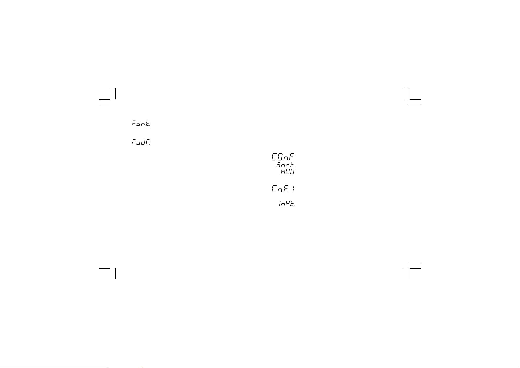
By or push-button it is possible to select between:
= (monitor) this selection allows you to monitor but
not to modify the value assigned to the
configuration parameters
= (modify) this selection allows you to monitor and
to modify the value assigned to the configuration
parameters.
NOTESNOTES
NOTES:
NOTESNOTES
1) During monitor mode, the instrument continues to operate as
in run time mode.
2) When modify mode is started, the instrument stops the
control and:
- sets to OFF the control outputs;
- turns to OFF the bargraph displays (MKP only);
- sets analog retransmissions to the retransmitted initial
scale value;
- sets alarms in no alarm condition;
- sets to OFF the events;
- disables the serial link;
- the time out will be removed.
3) When the modify mode is disabled by V101 (V101.3), the
or push-button pressure has no effect.
XKP-1-D1.pmd 25/05/2006, 11.2829
MONITOR MODEMONITOR MODE
MONITOR MODE
MONITOR MODEMONITOR MODE
During the run time mode, it is possible to monitor but not
modify all configuration parameters.
When it is desired to verify the instrument configuration,
proceed as follows:
1) Push the MENU push-button for more than 5 seconds: the
display will show:
.
2) Push the MENU push-button the display will show:
it shows that configuration group 1 is selected and it
encompasses all the input parameters.
The configuration parameter "Monitor mode" follows the
"Modify mode" sequence.
NOTESNOTES
NOTES:
NOTESNOTES
1) During monitor mode, the instrument continues to operate as
in run time mode.
29
Page 34
2) During monitor mode, if no push-button is depressed for
more than 10 s (or 30 s according to "t.out" [C.I10]
parameter setting), the instrument returns automatically to
CnF. 1CnF. 1
CnF. 1CnF. 1
CnF. 1
the normal display mode.
MODIFY MODEMODIFY MODE
MODIFY MODE
MODIFY MODEMODIFY MODE
1) By or push-button select the modify mode.
2) Push the MENU push-button.
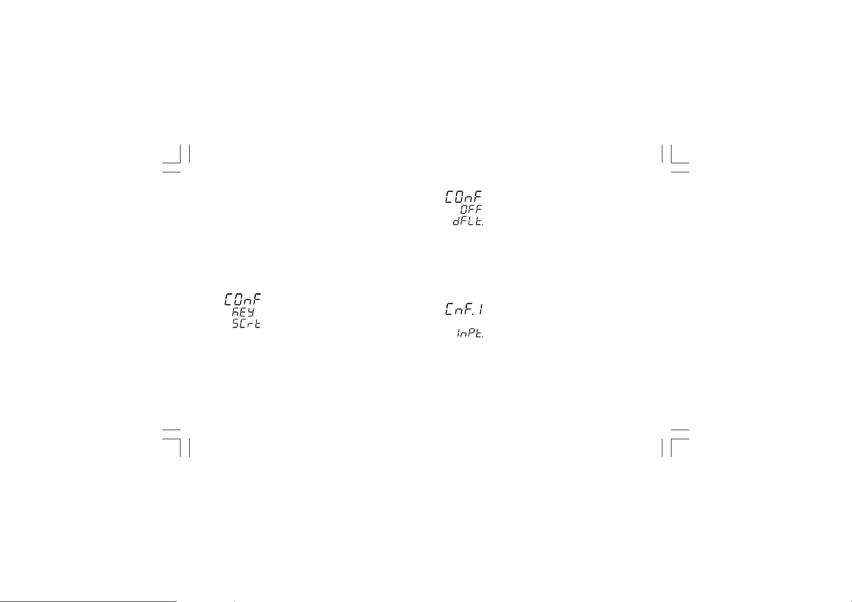
If a security code is applied to the configuration parameter,
the instrument will show:
3) By and push-button set a value equal to the security
code assigned to the configuration mode (see "Configuration
security code " at page 25).
If the code is different from the security code, the instrument
automatically returns to the first configuration display
otherwise the display will show:
XKP-1-D1.pmd 25/05/2006, 11.2830
The modify mode is started.
This display allows you to load the default configuration
parameter.
For more details see chapter "Default parameter" (see
Appendix A).
4) By or push-button select the OFF indication and push
the MENU push-button.
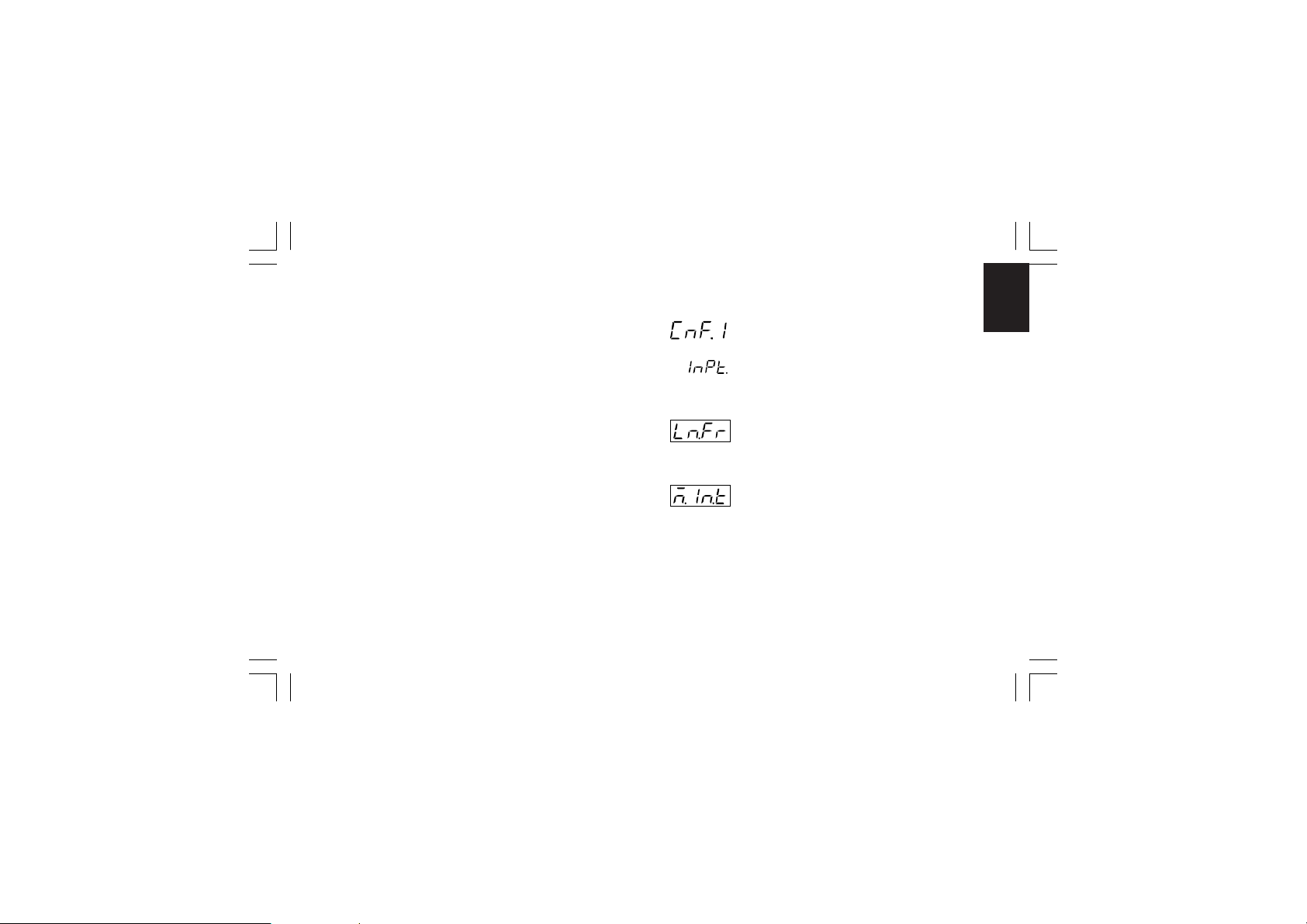
The display will show:
This is the starting display of the first group of configuration
parameters.
NOTESNOTES
NOTES:
NOTESNOTES
1) In the following pages we will describe all the parameters.
The instrument, however, will show only the parameters
related to the specific hardware and in accordance with the
30
Page 35
specific instrument configuration (i.e. setting OUT 3 different
from servo, all the parameters related to servomotor output
will be skipped).
2) During configuration parameters modify mode, the upper
display shows the selected parameter group, the lower
display shows the mnemonic code of the selected parameter
while the central display shows the value or status assigned
to the selected parameter.
3) For an easy consultation of this manual, a sheet named
"Reference parameter guide" with all the parameter
visualizations is enclosed.
The group (column) of configuration parameters are
identified by the "C" letter followed by A, b, etc.
The "code" formed by the column and row (example [C.d03])
is reported, in the user manual, before each parameter
description and allows you to quickly find out the respective
parameter.
When it is desired to exit from configuration modify mode
proceed as follows:
a) Push "MENU" push-button until the "Configuration group
END is displayed.
b) Pushing ”” or “” push-button select the "YES" indication.
c) Push “MENU” push-button. The instrument terminates the
configuration modify mode, it preforms an automatic reset
and restarts in the run time mode.
XKP-1-D1.pmd 25/05/2006, 11.2831
CONFIGURATION GROUP 1 [C.dxx]CONFIGURATION GROUP 1 [C.dxx]
CONFIGURATION GROUP 1 [C.dxx]
CONFIGURATION GROUP 1 [C.dxx]CONFIGURATION GROUP 1 [C.dxx]
MAIN AND AUXILIARY INPUT CONFIGURATION
Push the FUNC push-button
- Line frequency - [C.d01]- Line frequency - [C.d01]
- Line frequency - [C.d01]
- Line frequency - [C.d01]- Line frequency - [C.d01]
Range: 50 Hz
60 Hz
- Main input type and range - [C.d02] - Main input type and range - [C.d02]
- Main input type and range - [C.d02]
- Main input type and range - [C.d02] - Main input type and range - [C.d02]
Ranges:
* 1 = TC L From -100 to 900 °C
* 2 = TC J From -100 to 1000 °C
* 3 = TC K From -100 to 1370 °C
* 4 = TC T From -200 to 400 °C
* 5 = TC U From -200 to 600 °C
* 6 = TC E From -100 to 800 °C
7= TC N From -100 to 1400 °C
31
CnF. 1CnF. 1
CnF. 1CnF. 1
CnF. 1
Page 36

8= TC S From - 50 to 1760 °C
9= TC R From - 50 to 1760 °C
10= TC B From 0 to 1820 °C
CnF. 1CnF. 1
CnF. 1CnF. 1
CnF. 1
11= TC G (or W) From 0 to 2300 °C
12= TC D (or W3) From 0 to 2300 °C
13= TC C (or W5) From 0 to 2300 °C
14= TC Ni-Ni18%Mo From 0 to 1100 °C
* 15= RTD Pt100 From -200 to 850 °C
16= TC L From -150 to 1650 °F
17= TC J From -150 to 1830 °F
18= TC K From -150 to 2500 °F
19= TC T From -330 to 750 °F
20= TC U From -330 to 1110 °F
21= TC E From -150 to 1470 °F
22= TC N From -150 to 2550 °F
23= TC S From - 60 to 3200 °F
24= TC R From - 60 to 3200 °F
25= TC B From 32 to 3300 °F
26 = TC G ( or W) From 0 to 4170 °F
27= TC D (or W3) From 0 to 4170 °F
28= TC C (or W5) From 0 to 4170 °F
29= TC Ni-Ni18%Mo From 0 to 2000 °F
* 30= RTD Pt100 From -330 to 1560 °F
31 = Linear From 0 to 20 mA
32 = Linear From 4 to 20 mA
XKP-1-D1.pmd 25/05/2006, 11.2832
33 = Linear From 0 to 5 V
34 = Linear From 1 to 5 V
35 = Linear From 0 to 10 V
36 = Linear From 2 to 10 V
37 = Linear From 0 to 60 mV
38 = Linear From 12 to 60 mV
* For these ranges it is possible to select a read-out with one
decimal figure but the instrument could not display a
measure lower than -199.9 or higher than 999.9 and the
input range will be limited by it.
NOTESNOTES
NOTES:
NOTESNOTES
1) When a linear input is selected, the instrument automatically
sets the "readout initial scale value" [C.d05] equal to 0 and
the "readout full scale value" [C.d06] equal to 4000
2) When input type has been changed, the instrument
automatically forces:
- the "ñ.In.L" [C.d05], "SS.th" [C.I09] and "brG.L" [C.I03]
parameters to the new initial scale value,
- the "ñ.In.H" [C.d06] and "brG.H" [C.I04] parameter to the
new full scale value and
- the "ñ.In.d" [C.d03] parameter to "no decimal figure".
32
Page 37
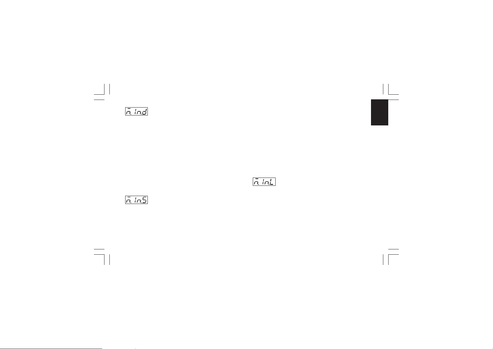
- Decimal point position - [C.d03]- Decimal point position - [C.d03]
- Decimal point position - [C.d03]
- Decimal point position - [C.d03]- Decimal point position - [C.d03]
----. = no decimal figure
Ranges:
---.- = one decimal figure
--.-- = two decimal figures
-.--- = three decimal figures
NOTESNOTES
NOTES:
NOTESNOTES
1) For main input type 1 to 6, 15 and 30 only the "no decimal
figure" and "one decimal figure" are selectable, the input
range is limited within -199.9 and 999.9 and it acts as an
input type changement.
2) For main input type 7 to 14 and 16 to 29 this parameter is
not available.
3) For linear input types (from 31 to 38) all positions are
available.
- Square root extraction for main input -- Square root extraction for main input -
- Square root extraction for main input -
- Square root extraction for main input -- Square root extraction for main input [C.d04][C.d04]
[C.d04]
Ranges: dIS = square root extraction disabled
NOTESNOTES
NOTES:
NOTESNOTES
1) This parameter is available only for main input type 31 to 38.
XKP-1-D1.pmd 25/05/2006, 11.2833
[C.d04][C.d04]
Enb = square root extraction enabled
2) When the square root extraction is enabled the values of the
following parameters:
- "ñ.In.L" (read-out - initial scale value [C.d05]),
- "ñ.In.H" (read-out - full scale value [C.d06]),
- "brG.L" (bargraph - initial scale value [C.I03]),
- "brG.H" (bargraph - full scale value [C.I04])
- "SS.th" (threshold to enable the soft start [C.I09])
must be positive or equal to zero.
Enabling the square root extraction the instrument verifies
the current value of the "ñ.In.L", "ñ.In.H", "brG.L", "brG.H"
and "SS.th" parameters and force to zero the eventual
negative values.
Read-out- initial scale value - [C.d05]Read-out- initial scale value - [C.d05]
-
Read-out- initial scale value - [C.d05]
Read-out- initial scale value - [C.d05]Read-out- initial scale value - [C.d05]
Ranges: - from -1999 to 9999 for linear input (Input range 31 to
NOTESNOTES
NOTES:
NOTESNOTES
1) The Read-out initial scale value can be higher than the
33
38),
- from 0 to 9999 for linear input with square root
extraction,
- from initial range value to "ñ.In.H" (read-out- full
scale value C.d06]) for TC/RTD input
Read-out - full scale value.
CnF. 1CnF. 1
CnF. 1CnF. 1
CnF. 1
Page 38
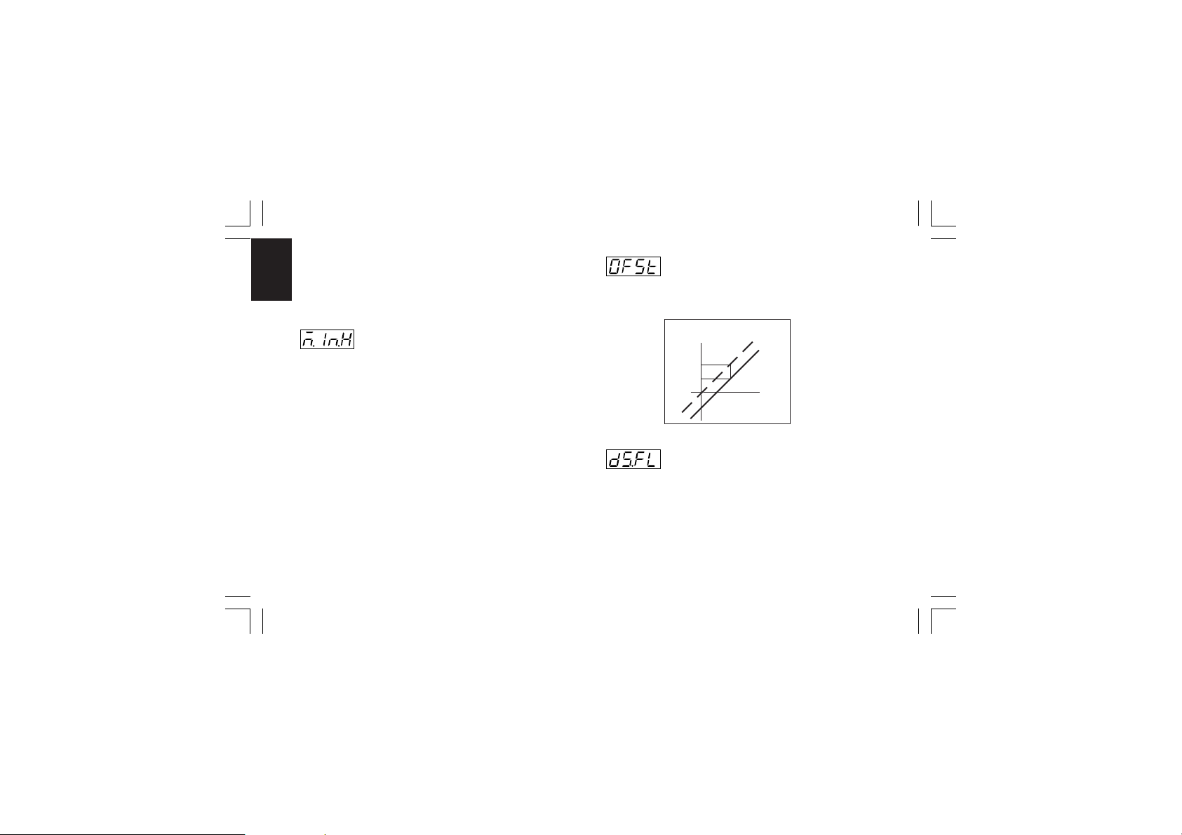
2) Changing the value of this parameter, the "brG.L" (bargraph
- initial scale value [C.I03]) and "rL" (set point low limit
[r.E12]) parameters will be realigned to it.
CnF. 1CnF. 1
CnF. 1CnF. 1
CnF. 1
If a linear input is selected, also the “SS.th” (threshold for
soft start [C.I09]) will be realigned to it.
- Read-out- full scale value - [C.d06]- Read-out- full scale value - [C.d06]
- Read-out- full scale value - [C.d06]
- Read-out- full scale value - [C.d06]- Read-out- full scale value - [C.d06]
Ranges: - from -1999 to 9999 for linear input (Input range 31 to
38),
- from 0 to 9999 for linear input with square root
extraction,
- from "ñ.In.L" (read-out- initial scale value [C.d05]) to
full range value for TC/RTD input.
NOTESNOTES
NOTES:
NOTESNOTES
1) Changing the value of this parameter, the "brG.H" (bargraph
- full scale value [C.I04]) and "rH" (set point high limit [r.E13])
parameters will be realigned to it.
2) The programmed input span, in absolute value, must be
greater than:
300 °C or 550 °F for TC inputs
100°C or 200 °F for RTD inputs
100 digits for linear inputs.
XKP-1-D1.pmd 25/05/2006, 11.2834
- Offset on the main input - [C.d07]- Offset on the main input - [C.d07]
- Offset on the main input - [C.d07]
- Offset on the main input - [C.d07]- Offset on the main input - [C.d07]
Ranges: from -500 to 500.
NOTENOTE
NOTE: the decimal point will be automatically positioned as
NOTENOTE
selected for the main input.
Read-out
OFSt
Real curve
Adjusted
curve
Input
- Filter on the displayed value - [C.d08]- Filter on the displayed value - [C.d08]
- Filter on the displayed value - [C.d08]
- Filter on the displayed value - [C.d08]- Filter on the displayed value - [C.d08]
Ranges: from 0 (no filter) to 8 seconds.
NOTENOTE
NOTE: this is a first order digital filter applied to the read-out of
NOTENOTE
the main input.
34
Page 39
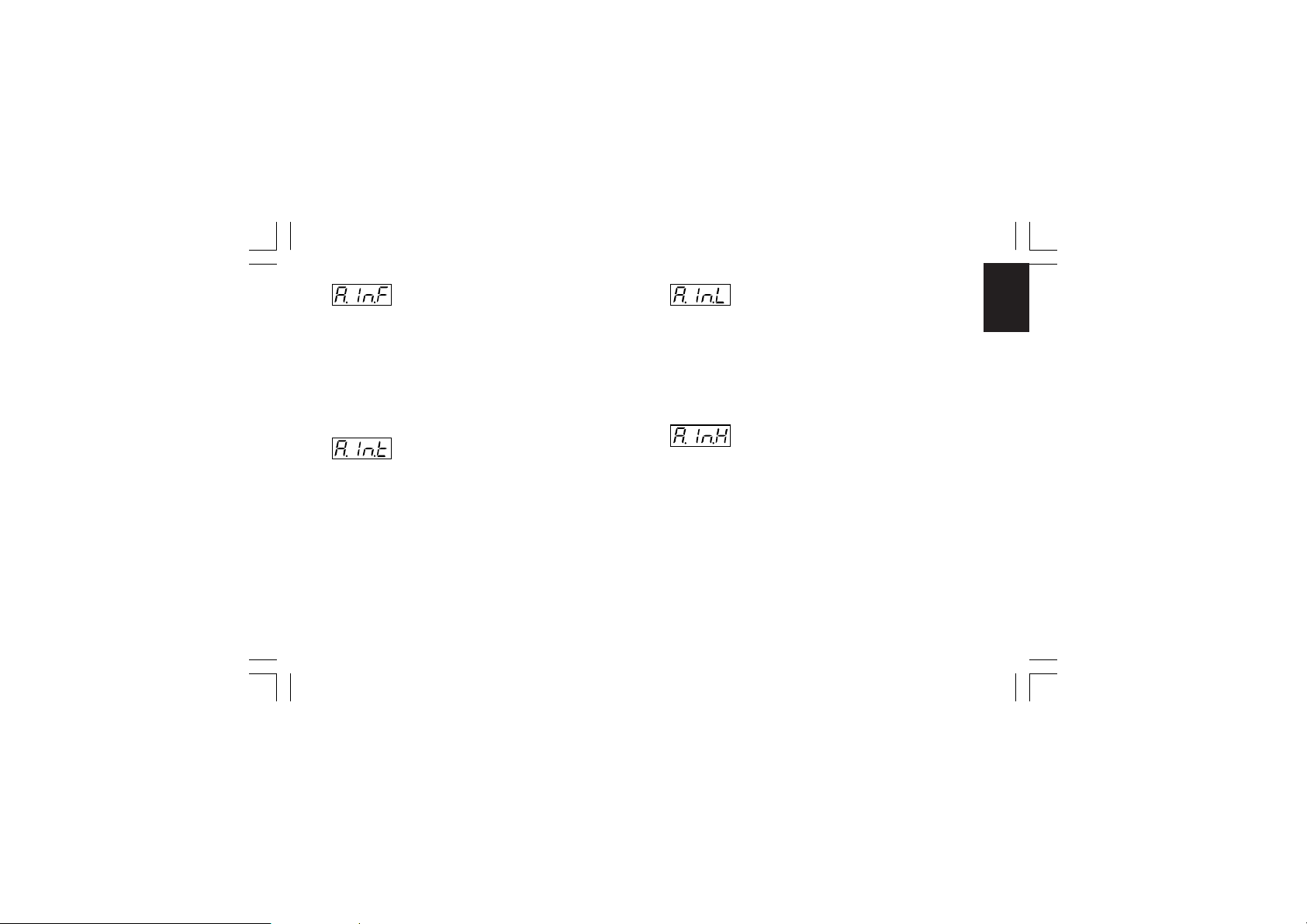
- Auxiliary input function - [C.d09]- Auxiliary input function - [C.d09]
- Auxiliary input function - [C.d09]
- Auxiliary input function - [C.d09]- Auxiliary input function - [C.d09]
Range: nonE = Input not used
bIAS = Input used as bias for local set point
NOTESNOTES
NOTES:
NOTESNOTES
1) When auxiliary input option is not mounted the middle
display will show “no.Pr” (not present).
2) When "bIAS" is selected, the instrument adds to the local set
point the value measured by the auxiliary input and scaled
by "A.In.L" [C.d11] and "A.In.H" [C.d12] parameters.
- Auxiliary input type- Auxiliary input type
- Auxiliary input type
- Auxiliary input type- Auxiliary input type
- [C.d10]- [C.d10]
- [C.d10]
- [C.d10]- [C.d10]
This parameter will be skipped when the auxiliary input option
is not mounted or "A.In.F" (auxiliary input function [C.d09]) is
equal to "nonE".
Range: 0-20 = 0−20 mA
4-20 = 4−20 mA
0- 5 = 0− 5 V
1- 5 = 1− 5 V
0-10 = 0−10 V
2-10 = 2−10 V
XKP-1-D1.pmd 25/05/2006, 11.2835
- Initial scale read-out of the auxiliary input- Initial scale read-out of the auxiliary input
- Initial scale read-out of the auxiliary input
- Initial scale read-out of the auxiliary input- Initial scale read-out of the auxiliary input
- [C.d11]- [C.d11]
- [C.d11]
- [C.d11]- [C.d11]
This parameter is available only when auxiliary input is
configured
Range: from -1999 to 9999
NOTENOTE
NOTE: the decimal point will be automatically positioned as
NOTENOTE
selected for the main input.
- Full scale read-out of the auxiliary input- Full scale read-out of the auxiliary input
- Full scale read-out of the auxiliary input
- Full scale read-out of the auxiliary input- Full scale read-out of the auxiliary input
- [C.d12]- [C.d12]
- [C.d12]
- [C.d12]- [C.d12]
This parameter is available only when auxiliary input is
configured.
Range: from -1999 to 9999
NOTENOTE
NOTE: the decimal point will be automatically positioned as
NOTENOTE
selected for the main input.
35
CnF. 1CnF. 1
CnF. 1CnF. 1
CnF. 1
Page 40
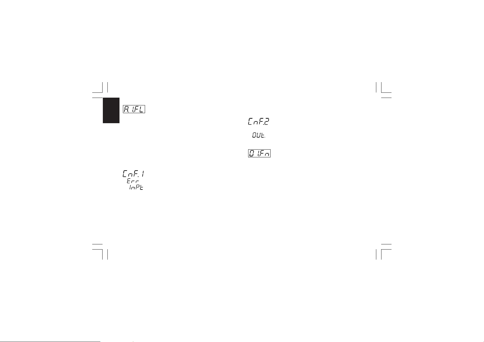
- Filter on auxiliary input - [C.d13]- Filter on auxiliary input - [C.d13]
- Filter on auxiliary input - [C.d13]
- Filter on auxiliary input - [C.d13]- Filter on auxiliary input - [C.d13]
This parameter is available only when auxiliary input is
CnF. 2CnF. 2
CnF. 2CnF. 2
CnF. 2
configured
Ranges: from 0 (no filter) to 8 seconds.
NOTENOTE
NOTE: this is a first order digital filter applied to the measured
NOTENOTE
value made by the auxiliary input.
General note about configuration group 1General note about configuration group 1
General note about configuration group 1
General note about configuration group 1General note about configuration group 1
Exiting from the configuration group 1 the instrument automatically verifies the programmed span for the linear input.
If it is wrong, the device will show:
Push the FUNC pushbutton more times until the "ñ.In.L"
[C.d05] or "ñ.In.H" [C.d06] are displayed and modify their value
in order to respect the minimum read-out span (see NOTE 2 of
the "ñ.In.H" [C.d06] parameter).
XKP-1-D1.pmd 25/05/2006, 11.2836
CONFIGURATION GROUP 2 [C.Exx]CONFIGURATION GROUP 2 [C.Exx]
CONFIGURATION GROUP 2 [C.Exx]
CONFIGURATION GROUP 2 [C.Exx]CONFIGURATION GROUP 2 [C.Exx]
OUTPUTS CONFIGURATION
- OUT 1 function - [C.E01]- OUT 1 function - [C.E01]
- OUT 1 function - [C.E01]
- OUT 1 function - [C.E01]- OUT 1 function - [C.E01]
Range:nonE =Output not used
ñAi n = Time proportional main control output
SECn =Time proportional secondary control output
ALr.1 = Alarm 1 output
Eun.1 =Event 1 output
NOTENOTE
NOTE: for Event description see "Event 1
NOTENOTE
function" [C.H.09] parameter.
36
Page 41
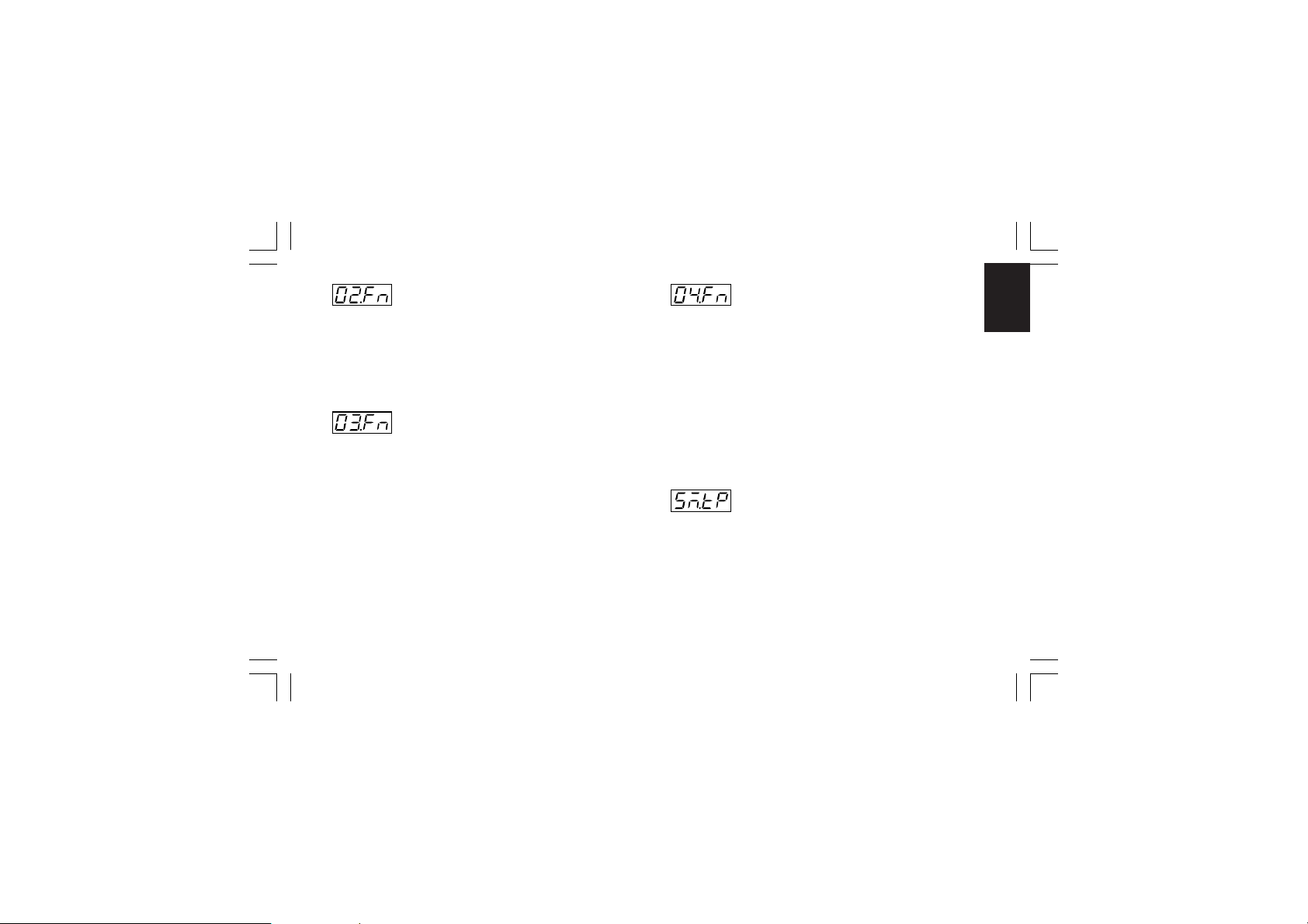
- OUT 2 function - [C.E02]- OUT 2 function - [C.E02]
- OUT 2 function - [C.E02]
- OUT 2 function - [C.E02]- OUT 2 function - [C.E02]
Range:nonE = Output not used
ñAi n = Time proportional main control output
SECn = Time proportional secondary control output
ALr.2 = Alarm 2 output
Eun.2 = Event 2 output
- OUT 3 function - [C.E03]- OUT 3 function - [C.E03]
- OUT 3 function - [C.E03]
- OUT 3 function - [C.E03]- OUT 3 function - [C.E03]
When the option is not mounted the middle display will show
“no.Pr” (not present).
Range:nonE =Output not used
ñAi n = Time proportional main control output
SECn =Time proportional secondary control output
ALr.3 = Alarm 3 output
Eun.3 =Event 3 output
ñC.Sñ =Servomotor control drive as main control
output
SC.Sñ= Servomotor control drive as secondary control
output
XKP-1-D1.pmd 25/05/2006, 11.2837
- OUT 4 function - [C.E04]- OUT 4 function - [C.E04]
- OUT 4 function - [C.E04]
- OUT 4 function - [C.E04]- OUT 4 function - [C.E04]
Range:nonE =Output not used
ñAi n = Time proportional main control output
SECn = Time proportional secondary control output
ALr.4 = Alarm 4 output
Eun.4 = Event 4 output
NOTESNOTES
NOTES:
NOTESNOTES
1) When option is not mounted the middle display will show
“no.Pr” (not present).
2) When servomotor control drive is hardware selected (see
"Output 3 and 4 selection" at pag. 21), the OUT 4 can be
used only as servomotor drive and this parameter will not be
shown.
- Servomotor type - [C.E05]- Servomotor type - [C.E05]
- Servomotor type - [C.E05]
- Servomotor type - [C.E05]- Servomotor type - [C.E05]
This parameter will be available only when servomotor control
drive is configured (“CnF.2 - O3.Fn” [C.E03]= “ñC.Sñ” or
“SC.Sñ”).
Range:CLSd = Close loop type
NOTENOTE
NOTE: this selection is available only if
NOTENOTE
feedback circuitry is mounted and selected.
OPEn = Open loop type.
37
CnF. 2CnF. 2
CnF. 2CnF. 2
CnF. 2
Page 42
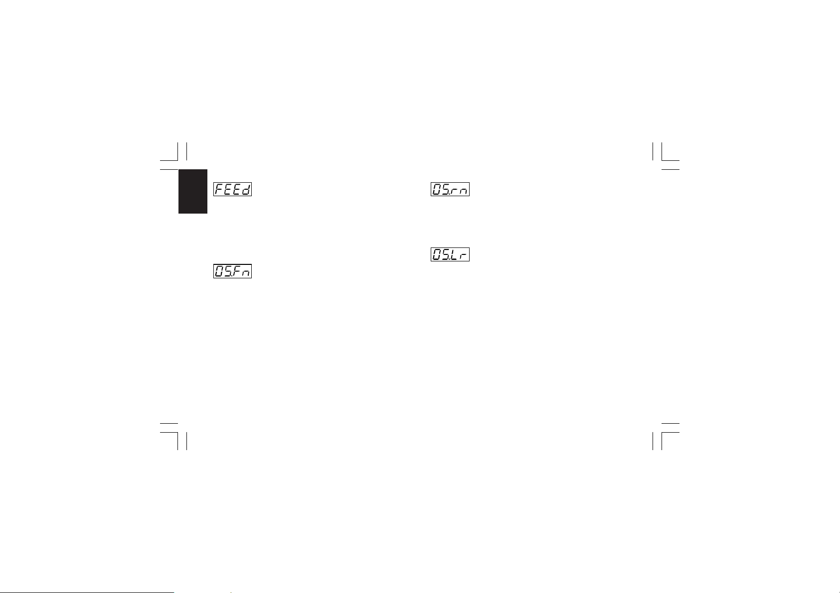
- Valve position indication - [C.E06]- Valve position indication - [C.E06]
- Valve position indication - [C.E06]
- Valve position indication - [C.E06]- Valve position indication - [C.E06]
This parameter will be displayed only when open loop
CnF. 2CnF. 2
CnF. 2CnF. 2
CnF. 2
servomotor control drive output is configured.
Range:Fb = The valve position is measured and displayed
no.Fb = The valve position is not measured
NOTENOTE
NOTE: If the feedback option is not mounted, this parameter
NOTENOTE
will be forced to “no.Fb” (no feedback).
- OUT 5 function - [C.E07]- OUT 5 function - [C.E07]
- OUT 5 function - [C.E07]
- OUT 5 function - [C.E07]- OUT 5 function - [C.E07]
Range:nonE =Output not used
ñAi n = Main control output (linear)
SECn =Secondary control output (linear)
PV.rt = Process variable retransmission
SP.rt = Operative set point retransmission
NOTENOTE
NOTE: When the option circuitry is not mounted the middle
NOTENOTE
display will show “no.Pr” (not present).
XKP-1-D1.pmd 25/05/2006, 11.2838
- OUT 5 range - [C.E08]- OUT 5 range - [C.E08]
- OUT 5 range - [C.E08]
- OUT 5 range - [C.E08]- OUT 5 range - [C.E08]
This parameter will be available only when Out 5 is configured
("O5.Fn" [C.E07] different from "nonE")
Range:0-20 = 0÷20 mA
4-20 = 4 ÷20 mA
- OUT 5 retransmission initial scale value- OUT 5 retransmission initial scale value
- OUT 5 retransmission initial scale value
- OUT 5 retransmission initial scale value- OUT 5 retransmission initial scale value
- [C.E09]- [C.E09]
- [C.E09]
- [C.E09]- [C.E09]
This parameter will be available only when Out 5 function
[C.E07] is configured as “PV.rt” or “SP.rt”
Range:From -1999 to 9999
NOTESNOTES
NOTES:
NOTESNOTES
1) Decimal point is positioned as previously selected at “CnF.1
- ñ.In.d” [C.d03])
2) The OUT 5 retransmission initial scale value can be higher
than OUT 5 retransmission full scale value [C.E.10].
38
Page 43
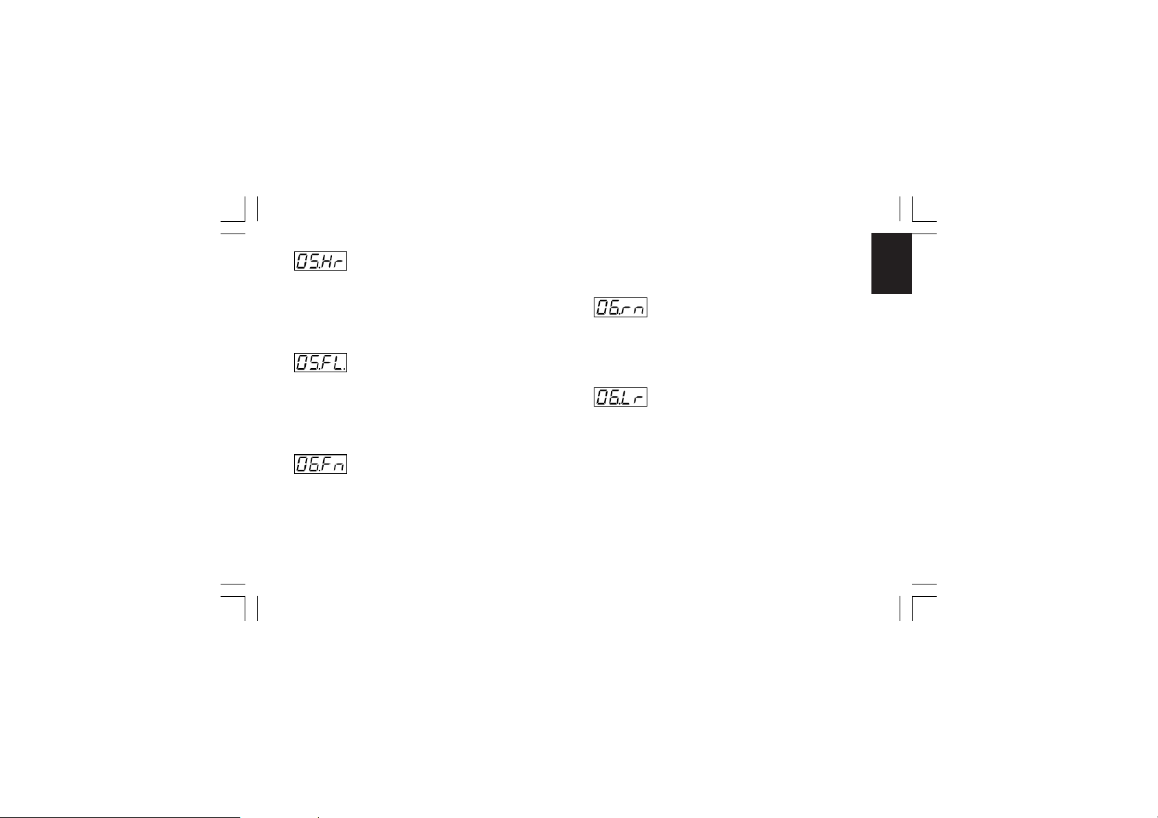
- OUT 5 retransmission full scale value- OUT 5 retransmission full scale value
- OUT 5 retransmission full scale value
- OUT 5 retransmission full scale value- OUT 5 retransmission full scale value
- [C.E10]- [C.E10]
- [C.E10]
- [C.E10]- [C.E10]
This parameter will be available only when Out 5 function
[C.E07] is configured as “PV.rt” or “SP.rt”
Range:From -1999 to 9999
NOTENOTE
NOTE: Decimal point is positioned as previously selected at
NOTENOTE
“CnF.1 - ñ.In.d” [C.d03])
- OUT 5 filter on the retransmitted value- OUT 5 filter on the retransmitted value
- OUT 5 filter on the retransmitted value
- OUT 5 filter on the retransmitted value- OUT 5 filter on the retransmitted value
- [C.E11]- [C.E11]
- [C.E11]
- [C.E11]- [C.E11]
This parameter will be available only when OUT 5 is configured
as process variable retransmission ("O5.Fn" [C.E07] is equal to
“PV.rt”).
Range: From 0 (no filter) to 8 seconds
NOTENOTE
NOTE: this is a first order digital filter applied to the
NOTENOTE
retransmitted output value.
- OUT 6 function - [C.E12]- OUT 6 function - [C.E12]
- OUT 6 function - [C.E12]
- OUT 6 function - [C.E12]- OUT 6 function - [C.E12]
Range:nonE = Output not used
ñAi n = Main control output (linear)
SECn = Secondary control output (linear)
PV.rt = Process variable retransmission
SP.rt = Operative set point retransmission
XKP-1-D1.pmd 25/05/2006, 11.2839
NOTENOTE
NOTE: When the option circuitry is not mounted the middle
NOTENOTE
display will show “no.Pr” (not present).
- OUT 6 range - [C.E13]- OUT 6 range - [C.E13]
- OUT 6 range - [C.E13]
- OUT 6 range - [C.E13]- OUT 6 range - [C.E13]
This parameter will be available only when Out 6 is configured
("O6.Fn" [C.E12] different from "nonE")
Range:0-20 = 0÷20 mA
4-20 = 4÷20 mA
- OUT 6 retransmission initial scale value- OUT 6 retransmission initial scale value
- OUT 6 retransmission initial scale value
- OUT 6 retransmission initial scale value- OUT 6 retransmission initial scale value
- [C.E14]- [C.E14]
- [C.E14]
- [C.E14]- [C.E14]
This parameter will be available only when Out 6 function
[C.E12] is configured as “PV.rt” or “SP.rt”
Range:From -1999 to 9999
NOTESNOTES
NOTES:
NOTESNOTES
1) Decimal point is positioned as previously selected at “CnF.1
- ñ.In.d” [C.d03])
2) The OUT 6 retransmission initial scale value can be higher
than OUT 6 retransmission full scale value [C.E.15].
39
CnF. 2CnF. 2
CnF. 2CnF. 2
CnF. 2
Page 44
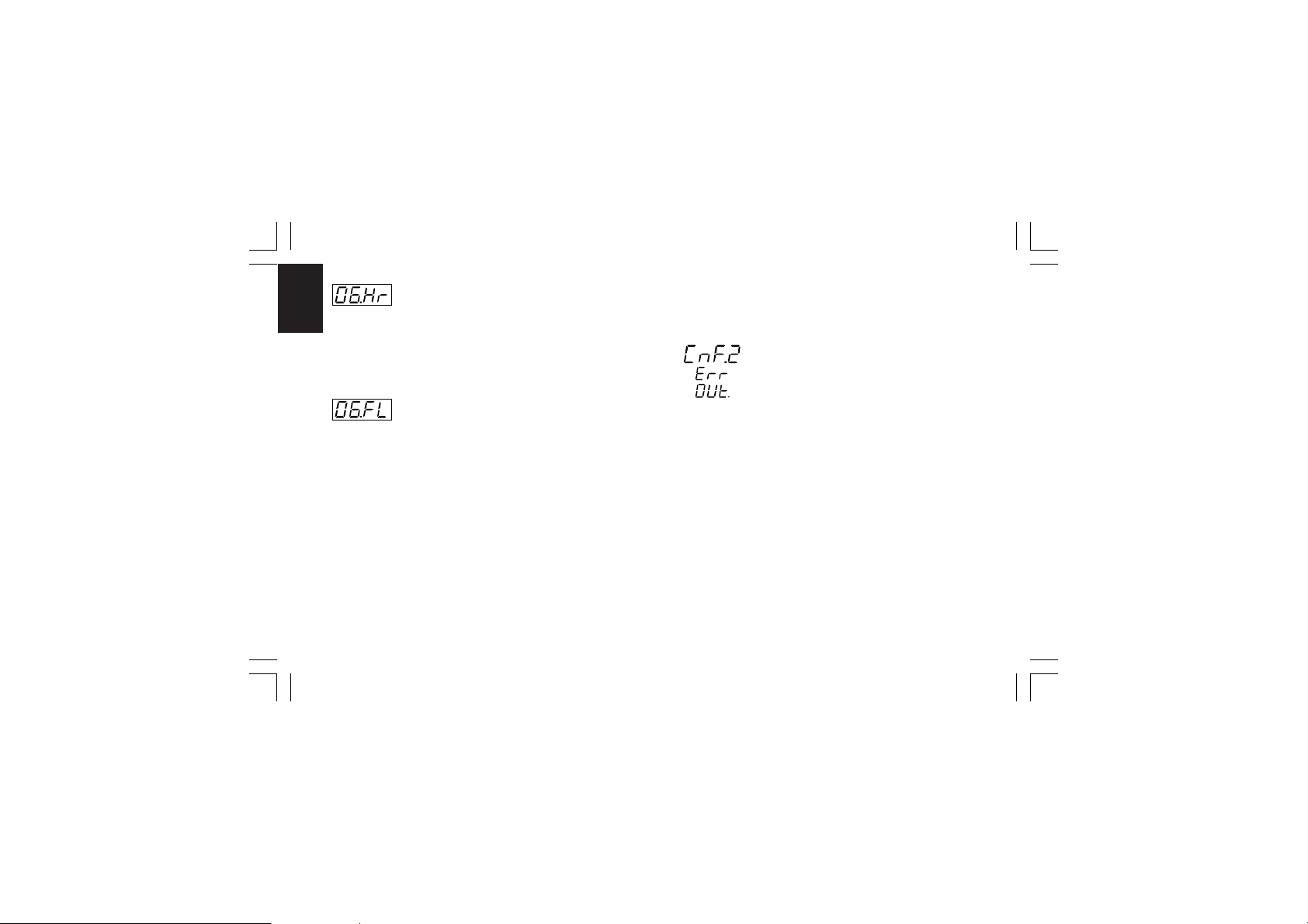
- OUT 6 retransmission full scale value- OUT 6 retransmission full scale value
- OUT 6 retransmission full scale value
- OUT 6 retransmission full scale value- OUT 6 retransmission full scale value
- [C.E15]- [C.E15]
- [C.E15]
This parameter will be available only when Out 6 function
CnF. 2CnF. 2
CnF. 2CnF. 2
CnF. 2
[C.E12] is configured as “PV.rt” or “SP.rt”
- [C.E15]- [C.E15]
Range:From -1999 to 9999
NOTENOTE
NOTE: Decimal point is positioned as previously selected at
NOTENOTE
“CnF.1 - ñ.In.d” [C.d03])
- OUT 6 filter on the retransmitted value- OUT 6 filter on the retransmitted value
- OUT 6 filter on the retransmitted value
- OUT 6 filter on the retransmitted value- OUT 6 filter on the retransmitted value
- [C.E16]- [C.E16]
- [C.E16]
- [C.E16]- [C.E16]
This parameter will be available only when OUT 6 is configured
as process variable retransmission ("O6.Fn" [C.E12] is equal to
“PV.rt”).
Range: From 0 (no filter) to 8 seconds
NOTENOTE
NOTE: this is a first order digital filter applied to the
NOTENOTE
retransmitted output value.
XKP-1-D1.pmd 25/05/2006, 11.2840
General note about configuration group 2General note about configuration group 2
General note about configuration group 2
General note about configuration group 2General note about configuration group 2
I) Exiting from the configuration group 2 the instrument
automatically verifies the congruence of all parameters.
If a wrong setting is detected, the device will show:
Pushing the FUNC pushbutton, verify (and modify if
necessary) all group 2 parameter settings in order to assure
that the following conditions are respected:
a ) Only one of the 6 outputs is configured as main output
(“ñAin”)
b) Only one of the 6 outputs is configured as secondary
output (“SECn”)
c) If only one control output is configured, it should be the
main control output (“ñAin”)
d) The servomotor must be “close loop” type if it is one of
two control outputs.
NOTENOTE
NOTE: The instrument may be used as an indicator, so that this
NOTENOTE
test is satisfied even if no output is configured as control output
40
Page 45
I I ) Exiting from the configuration group 2 also the following
actions are automatically performed:
A) The "Añ.UL” parameter ("Output value for auto to manual
transfer" [C.G04]) will be forced to "bumpless" (“buñ”) if:
1) its value is < 0 and only one control output is configured;
2) servomotor open loop is configured.
B )The “SF.Cn” parameter ("Condition for output safety value"
[C.G09]) will be forced to "standard" (“Std.”) if it is not
complied with configured control output type.
C ) The “SF.UL” parameter ("Output safety value" [C.G10]) will
be forced to 0 if only one control output is configured and its
value is < 0.
D ) The “Fd.Fn” parameter ("Out failure detection current
measurement" [C.I11]) will be forced to “nonE” if it is
assigned to a control output different from a time
proportional output.
E ) The “Fd.Ou” parameter ("Out failure detection output
assignment" [C.I13]) will be forced to “nonE” if it is
assigned to an output configured as control output.
F) The “IP” parameter ("Integral pre-load" [r.d05]) will be forced
to 50.0 if only one control output is configured and its value
is < 0.
XKP-1-D1.pmd 25/05/2006, 11.2841
CONFIGURATION GROUP 3 [C.Fxx]CONFIGURATION GROUP 3 [C.Fxx]
CONFIGURATION GROUP 3 [C.Fxx]
CONFIGURATION GROUP 3 [C.Fxx]CONFIGURATION GROUP 3 [C.Fxx]
CONTROL OUTPUT CONFIGURATION
- Split range - [C.F01]- Split range - [C.F01]
- Split range - [C.F01]
- Split range - [C.F01]- Split range - [C.F01]
This parameter will be available only when two control outputs
are configured.
Range:dIS = Split range feature is not required
Enb = Split range feature is required
NOTE about the split rangeNOTE about the split range
NOTE about the split range.
NOTE about the split rangeNOTE about the split range
This function allows you to drive by the same control action,
two physical outputs (two actuators) with different bias and
gain.
41
CnF. 3CnF. 3
CnF. 3CnF. 3
CnF. 2CnF. 2
CnF. 2CnF. 2
CnF. 3
CnF. 2
Page 46
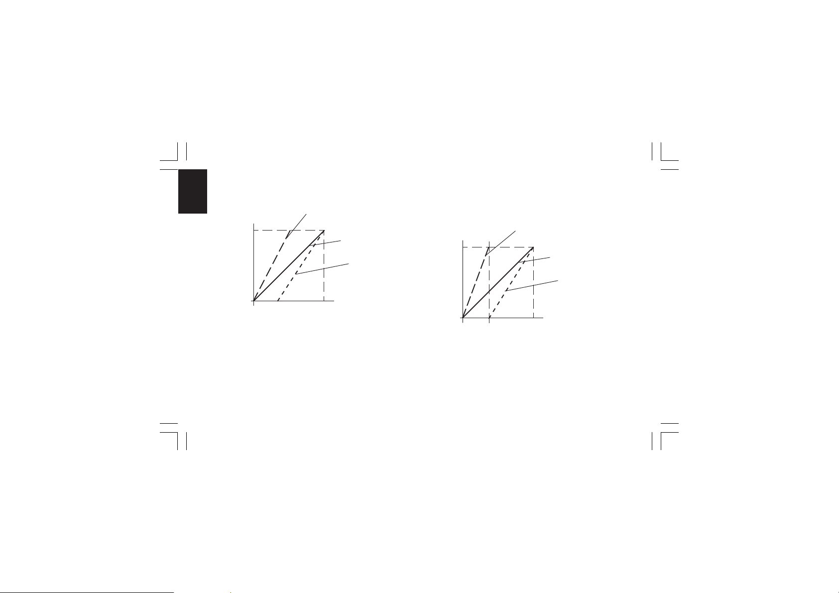
The relation between the Calculated Power Output and the
resulting real outputs are shown below:
CnF. 3CnF. 3
CnF. 3CnF. 3
CnF. 3
Real PWR
Output
First split
output (MAIN)
100 %
Standard curve
Second split
output
(Secondary)
0 %
100 %
Calculated
PWR Output
ABCD
where:
- for the first split output (MAIN)
Bias 1 = -A
Gain 1 = 100 / (B - A)
- For the second split output (SECONDARY)
Bias 2 = -C
Gain 2 = 100 / (D - C)
XKP-1-D1.pmd 25/05/2006, 11.2842
FOR EXAMPLEFOR EXAMPLE
FOR EXAMPLE:
FOR EXAMPLEFOR EXAMPLE
Let's suppose that the first split output operates from 0 % to
33.3 % of the calculated output while the second one operates
from 33.3 % to the 100 % of the calculated output.
Real PWR
Output
First split
output (MAIN)
100 %
Standard curve
Second split
output
(Secondary)
0 %
A
B e C
33.3 %
D
100 %
Calculated
PWR Output
Where: A = 0 %
B = C = 33.3 %
D = 100 %
42
Page 47
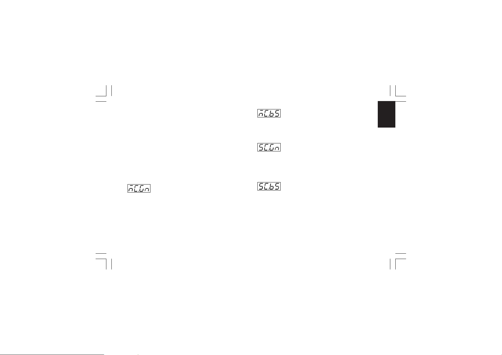
We will set:
Bias 1 = 0
Gain 1 = 100 / (33.3 - 0) = 3
Bias 2 = - 33.3
Gain 2 = 100 / (100 - 33.3) = 1,5
The bias and gain of the two split outputs are the following:
“ñC.bS” [C.F03] is the Bias 1 applied to the main output
“ñC.Gn” [C.F02] is the Gain 1 applied to the main output
“SC.bS” [C.F05] is the Bias 2 applied to the secondary output
“SC.Gn” [C.F04] is the Gain 2 applied to the secondary output
- Main control output gain - [C.F02]- Main control output gain - [C.F02]
- Main control output gain - [C.F02]
- Main control output gain - [C.F02]- Main control output gain - [C.F02]
This parameter will be available only when the split range is
enabled ("SPLt." [C.F01] = "Enb").
Range: from 0.50 to 5.00.
XKP-1-D1.pmd 25/05/2006, 11.2843
- Main control output bias - [C.F03]- Main control output bias - [C.F03]
- Main control output bias - [C.F03]
- Main control output bias - [C.F03]- Main control output bias - [C.F03]
This parameter will be available only when the split range is
enabled ("SPLt." [C.F01] = "Enb").
Range: from -100.0 to 100.0 % of the output span.
- Secondary control output gain - [C.F04]- Secondary control output gain - [C.F04]
- Secondary control output gain - [C.F04]
- Secondary control output gain - [C.F04]- Secondary control output gain - [C.F04]
This parameter will be available only when the split range is
enabled ("SPLt." [C.F01] = "Enb").
Range: from 0.50 to 5.00
- Secondary control output bias - [C.F05]- Secondary control output bias - [C.F05]
- Secondary control output bias - [C.F05]
- Secondary control output bias - [C.F05]- Secondary control output bias - [C.F05]
This parameter will be available only when the split range is
enabled ("SPLt." [C.F01] = "Enb").
Range: from -100.0 to 100.0 % of the output span.
43
CnF. 3CnF. 3
CnF. 3CnF. 3
CnF. 3
Page 48
- Main control output conditioning - [C.F06]- Main control output conditioning - [C.F06]
- Main control output conditioning - [C.F06]
- Main control output conditioning - [C.F06]- Main control output conditioning - [C.F06]
This parameter will be available only when main control output
CnF. 3CnF. 3
CnF. 3CnF. 3
CnF. 3
is configured.
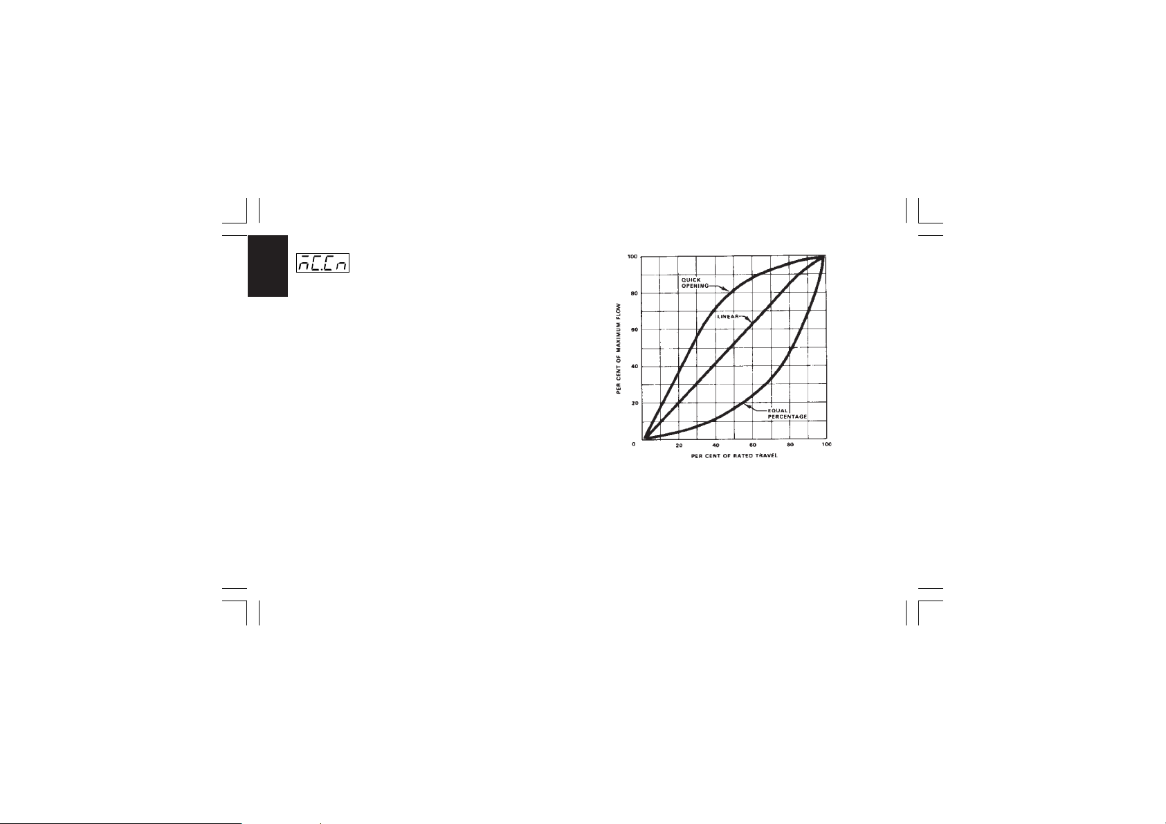
Range:norñ = The control output is calculated by the PID.
CñPL = The control output is complemented (100-PID
calculated value).
Ouic = The control output is conditioned to match a
“QUICK OPENING” flow characteristic.
Eo u = The control output is conditioned to match an
“EQUAL PERCENTAGE” flow characteristic.
NOTE about output conditioningNOTE about output conditioning
NOTE about output conditioning
NOTE about output conditioningNOTE about output conditioning
Sometimes non linear valves are used where a linear valve is
suitable.
In these cases, it is advisable to linearize the ratio between flow
rate and valve travel in order to obtain a better control of the
process.
This instrument allows you to select an output linearization in
accordance with the two most common valve flow characteristics:
- Quick opening
- Equal percentage.
XKP-1-D1.pmd 25/05/2006, 11.2844
44
Page 49
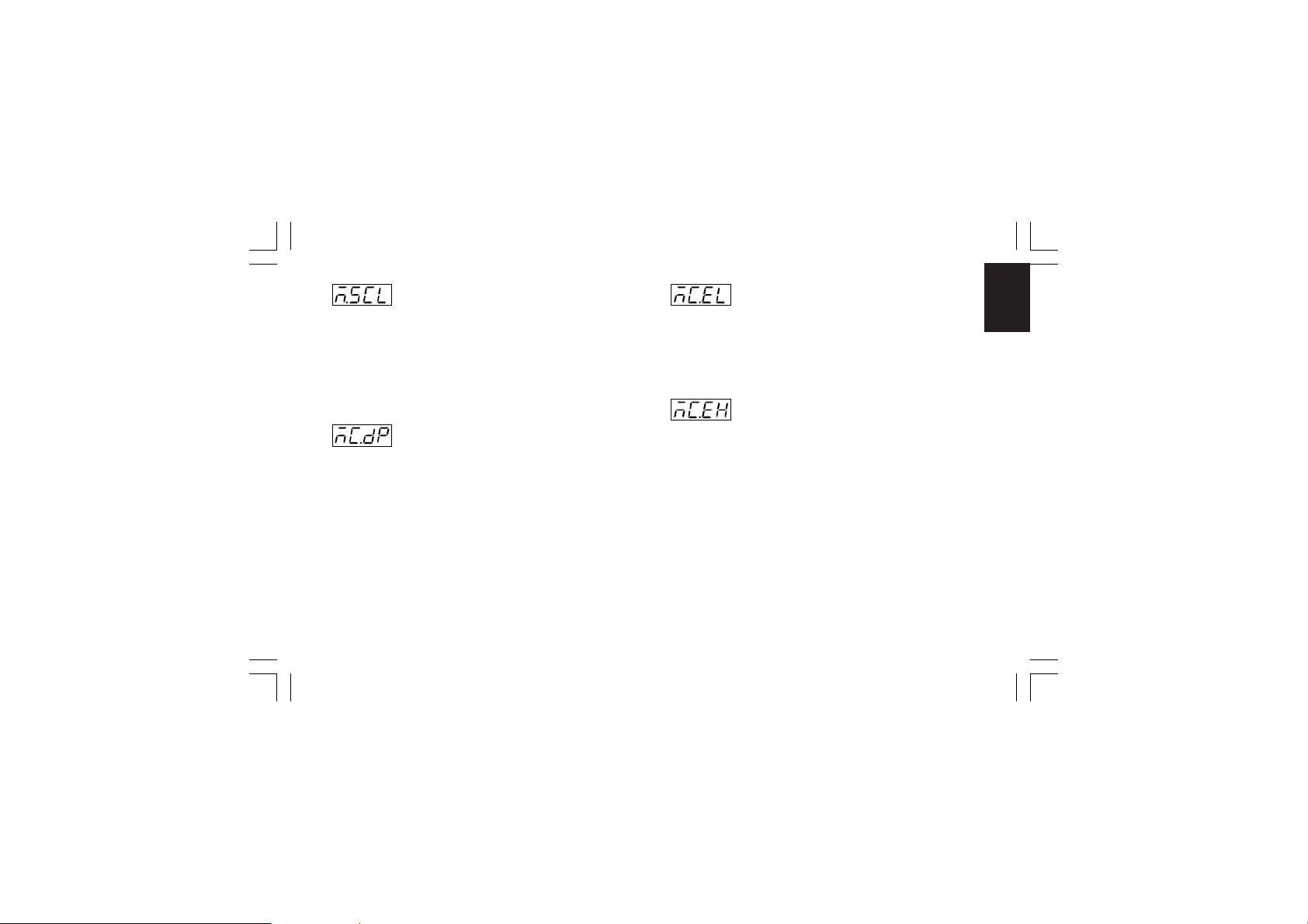
- Main control output in engineering unit- Main control output in engineering unit
- Main control output in engineering unit
- Main control output in engineering unit- Main control output in engineering unit
- [C.F07]- [C.F07]
- [C.F07]
This parameter will be available only when main control output
is configured.
Range:nO = Scalable is not required
NOTENOTE
NOTE: This scaling allows you to display the output value in
NOTENOTE
engineering units instead of in percent.
This parameter will be available only when "ñ.SCL" ("Main
control output in engineering units" [C.F07]) is set to "YES".
Range:
- [C.F07]- [C.F07]
YE S = Scalable is required
- Main output decimal point position - [C.F08]- Main output decimal point position - [C.F08]
- Main output decimal point position - [C.F08]
- Main output decimal point position - [C.F08]- Main output decimal point position - [C.F08]
----. = No decimal figure
---.- = One decimal figure.
--.-- = Two decimal figures.
XKP-1-D1.pmd 25/05/2006, 11.2845
- Main output initial scale readout - [C.F09]- Main output initial scale readout - [C.F09]
- Main output initial scale readout - [C.F09]
- Main output initial scale readout - [C.F09]- Main output initial scale readout - [C.F09]
This parameter will be available only when "ñ.SCL" ("Main
control output in engineering units" [C.F07]) is set to "YES".
Range: from -199 to 999
NOTENOTE
NOTE: The Main output initial scale value can be higher than
NOTENOTE
the Main output full scale value.
- Main output full scale readout - [C.F10]- Main output full scale readout - [C.F10]
- Main output full scale readout - [C.F10]
- Main output full scale readout - [C.F10]- Main output full scale readout - [C.F10]
This parameter will be available only when "ñ.SCL" ("Main
control output in engineering units" [C.F07]) is set to "YES".
Range: from -199 to 999
45
CnF. 3CnF. 3
CnF. 3CnF. 3
CnF. 3
Page 50
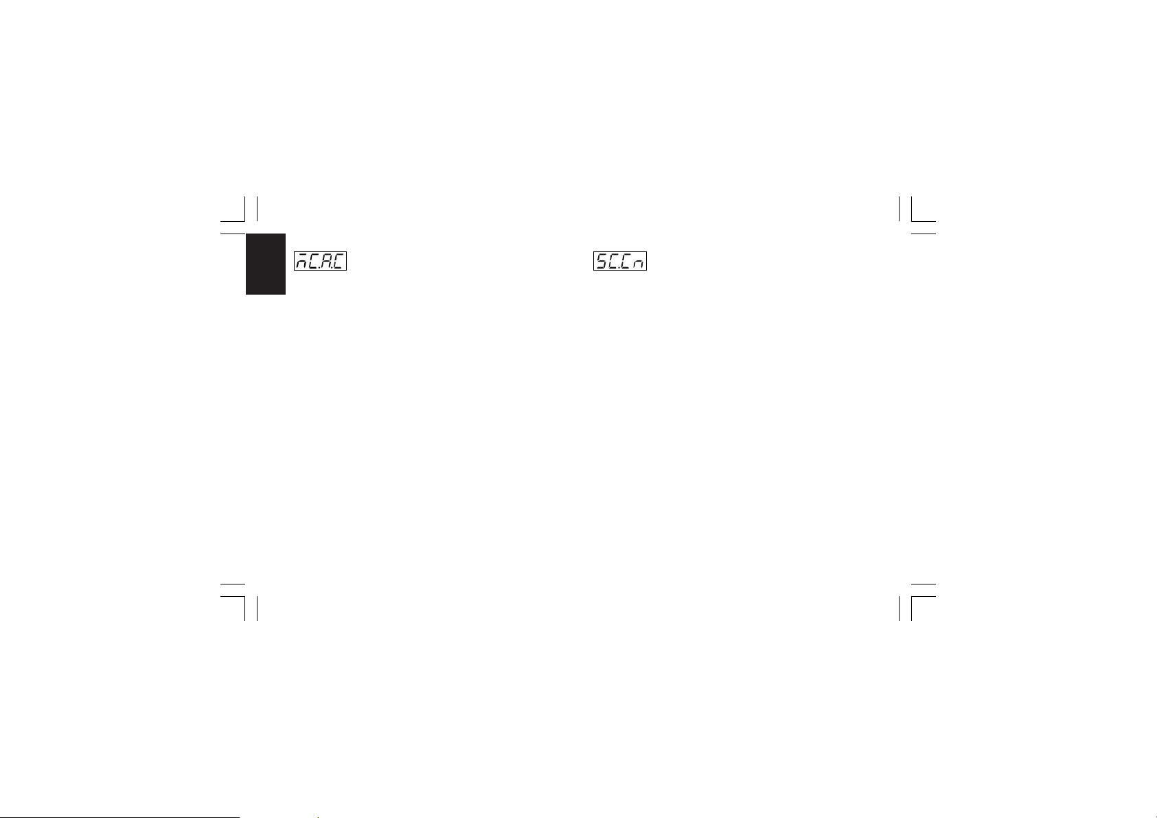
- Main output auxiliary conditioning - [C.F11]- Main output auxiliary conditioning - [C.F11]
- Main output auxiliary conditioning - [C.F11]
- Main output auxiliary conditioning - [C.F11]- Main output auxiliary conditioning - [C.F11]
This parameter will be available only when main control output
CnF. 3CnF. 3
CnF. 3CnF. 3
CnF. 3
is configured and “ñC.Cn” ("Main control output conditioning"
[C.F06]) is different from “norñ”.
Range:bEFr = The functions listed at Note (*) are calculated
before before
before to apply the action selected by “ñC.Cn”
before before
("Main control output conditioning" [C.F06])
parameter.
AFtr = The functions listed at Note (*) are calculated
after after
after to apply the action selected by “ñC.Cn”
after after
(“Main control output conditioning” [C.F06])
parameter.
Note (*)Note (*)
Note (*)
Note (*)Note (*)
- "Main control output limiters" - for more details see [r.E04]
and [r.E05] parameters.
- "Main control output max rate of rise" (see [r.E06]).
- "Control output display value" - for more details see "Display
function during programmer mode" paragraph at pag. 106
and [C.F07], [C.F08], [C.F09] and [C.F10] parameters.
- "Threshold for alarm on control output value" - for more
details see [r.F01], [r.F05] [r.F09] and [r.F13] parameters.
- The control output value displayed by bargraph.
XKP-1-D1.pmd 25/05/2006, 11.2846
- Secondary control output conditioning- Secondary control output conditioning
- Secondary control output conditioning
- Secondary control output conditioning- Secondary control output conditioning
- [C.F12]- [C.F12]
- [C.F12]
- [C.F12]- [C.F12]
This parameter will be available only when secondary control
output is configured.
Range:norñ = The control output is calculated by the PID
CñPL = The control output is complemented (100-PID
calculated value)
Ouic = The control output is conditioned to match a
“QUICK OPENING” flow characteristic
Eo u = The control output is conditioned to match an
“EQUAL PERCENTAGE” flow characteristic
For more details see also
NOTE about output conditioning NOTE about output conditioning
NOTE about output conditioning at
NOTE about output conditioning NOTE about output conditioning
page 44.
46
Page 51
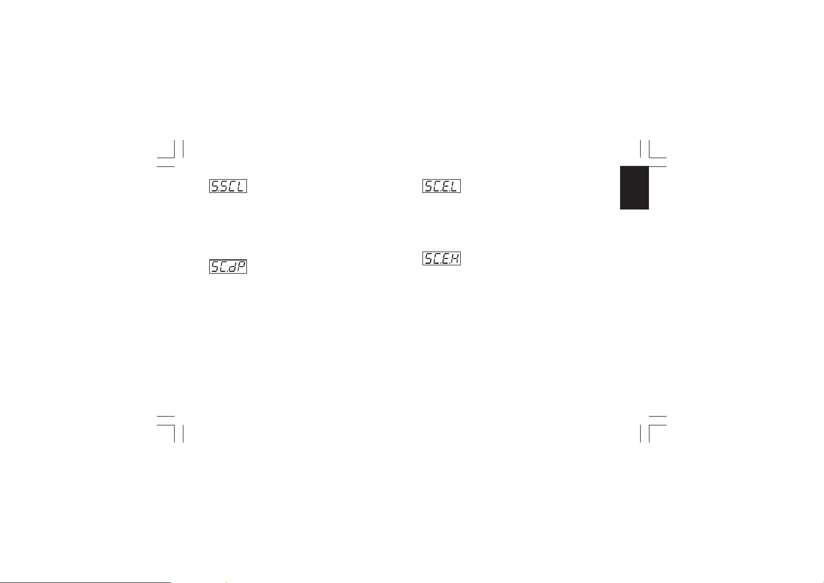
- Secondary control output in engineering unit- Secondary control output in engineering unit
- Secondary control output in engineering unit
- Secondary control output in engineering unit- Secondary control output in engineering unit
- [C.F13]- [C.F13]
- [C.F13]
This parameter will be available only when secondary control
output is configured.
Range:nO = Scalable is not required
NOTENOTE
NOTE: This scaling allows to display the output value in
NOTENOTE
engineering units instead of in percent.
This parameter will be available only when "S.SCL" ("Secondary control output in engineering units" [C.F13]) is set to "YES".
Range:
- [C.F13]- [C.F13]
YE S = Scalable is required
- Secondary control output decimal point- Secondary control output decimal point
- Secondary control output decimal point
- Secondary control output decimal point- Secondary control output decimal point
position - [C.F14]position - [C.F14]
position - [C.F14]
position - [C.F14]position - [C.F14]
----. = No decimal figure
---.- = One decimal figure.
--.-- = Two decimal figures.
XKP-1-D1.pmd 25/05/2006, 11.2847
- Secondary control output initial scale value- Secondary control output initial scale value
- Secondary control output initial scale value
- Secondary control output initial scale value- Secondary control output initial scale value
- [C.F15]- [C.F15]
- [C.F15]
This parameter will be available only when "S.SCL" ("Secondary control output in engineering units" [C.F13]) is set to "YES".
Range: from -199 to 999
NOTENOTE
NOTE: The secondary control output initial scale value can be
NOTENOTE
higher than the secondary control output full scale value.
This parameter will be available only when "S.SCL" ("Secondary control output in engineering units" [C.F13]) is set to "YES".
Range: From -199 to 999
47
- [C.F15]- [C.F15]
- Secondary control output full scale value- Secondary control output full scale value
- Secondary control output full scale value
- Secondary control output full scale value- Secondary control output full scale value
- [C.F16]- [C.F16]
- [C.F16]
- [C.F16]- [C.F16]
CnF. 3CnF. 3
CnF. 3CnF. 3
CnF. 3
Page 52
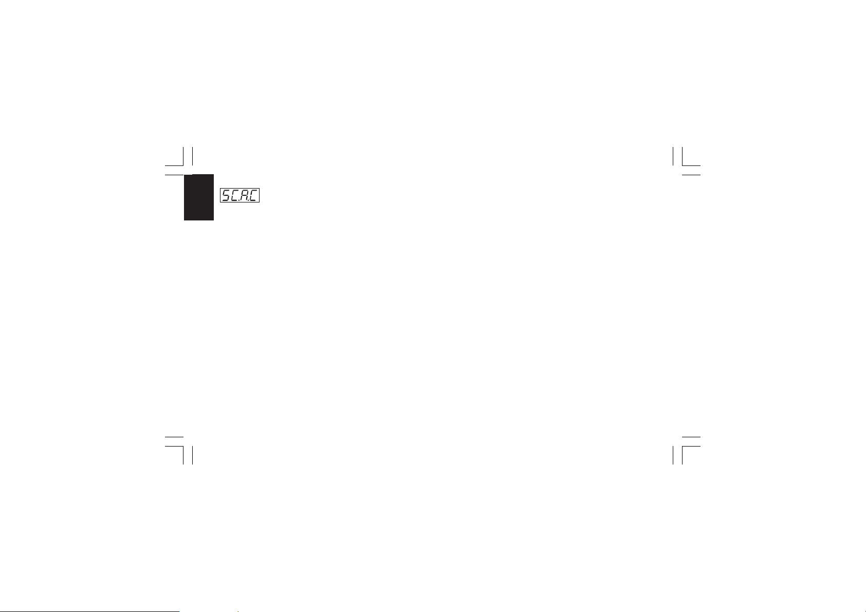
- Secondary output auxiliary conditioning- Secondary output auxiliary conditioning
- Secondary output auxiliary conditioning
- Secondary output auxiliary conditioning- Secondary output auxiliary conditioning
- [C.F17]- [C.F17]
- [C.F17]
This parameter will be available only when secondary control
CnF. 3CnF. 3
CnF. 3CnF. 3
CnF. 3
CnF. 4CnF. 4
CnF. 4CnF. 4
CnF. 4
output is configured and “SC.Cn” ("Secondary control output
- [C.F17]- [C.F17]
conditioning" [C.F12]) is different from “norñ”.
Range:bEFr = The functions listed at Note (**) are calculated
before before
before to apply the action selected by “SC.Cn”
before before
("Secondary control output conditioning"
[C.F12]) parameter.
AFtr = The functions listed at Note (**) are calculated
after after
after to apply the action selected by “SC.Cn”
after after
(“Secondary control output conditioning”
[C.F12]) parameter.
Note (**)Note (**)
Note (**)
Note (**)Note (**)
- "Secondary control output limiters" - for more details see
[r.E08] and [r.E09] parameters.
- "Secondary control output max rate of rise" (see [r.E10]).
- "Secondary control output display value" - for more details
see "Display function during programmer mode" paragraph
at pag. 106 and [C.F13], [C.F14], [C.F15] and [C.F16]
parameters.
- "Threshold for alarm on control output value" - for more
details see [r.F01], [r.F05] [r.F09] and [r.F13] parameters.
- The secondary control output value displayed by bargraph.
XKP-1-D1.pmd 25/05/2006, 11.2848
General note about configuration group 3General note about configuration group 3
General note about configuration group 3
General note about configuration group 3General note about configuration group 3
Exiting from the configuration group 3 the instrument automatically tests the "SPLt" parameter (Split range [C.F01]). When
"SPLt." parameter is enabled (= "Enb"), the instrument
performs the following actions:
1) If “Añ.UL” parameter ("Output value for AUTO to MAN
transfer [C.G04]) is lower than 0, it will be forced to “buñ“.
2) If the “SF.UL” parameter ("Output safety value" [C.G10])
is lower than zero, it will be forced to zero.
3) If the “IP” parameter ("Integral pre-load" [r.d05] is lower than
zero, it will be forced to 50.0.
48
Page 53
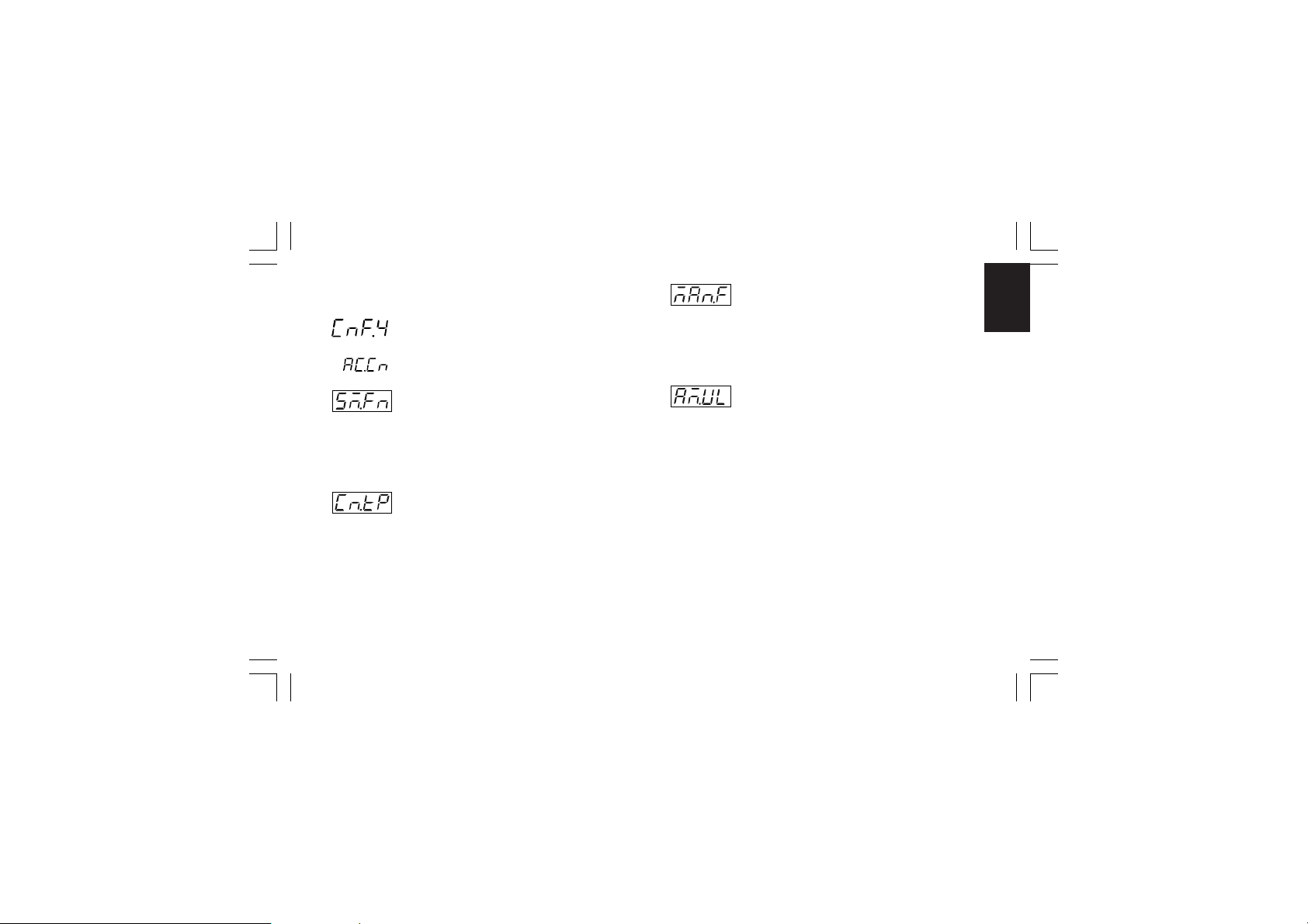
CONFIGURATION GROUP 4 [C.Gxx]CONFIGURATION GROUP 4 [C.Gxx]
CONFIGURATION GROUP 4 [C.Gxx]
CONFIGURATION GROUP 4 [C.Gxx]CONFIGURATION GROUP 4 [C.Gxx]
AUXILIARY CONTROL CONFIGURATION
- Smart function - [C.G01]- Smart function - [C.G01]
- Smart function - [C.G01]
- Smart function - [C.G01]- Smart function - [C.G01]
This parameter will be available only when at least one control
output is configured.
Range:dIS = Smart function disabled.
Enb = Smart function may be enabled.
- Control action type - [C.G02]- Control action type - [C.G02]
- Control action type - [C.G02]
- Control action type - [C.G02]- Control action type - [C.G02]
This parameter will be available only when at least one control
output is configured.
Upper display: CnF.4
Lower display: Cn.tP
Range:Pid = The process is controlled by PID actions.
Pi = The process is controlled by PI actions.
XKP-1-D1.pmd 25/05/2006, 11.2849
- Manual function - [C.G03]- Manual function - [C.G03]
- Manual function - [C.G03]
- Manual function - [C.G03]- Manual function - [C.G03]
This parameter will be available only when at least one control
output is configured.
Range:dIS = Manual function disabled.
Enb = Manual function may be enabled.
- Output value for AUTO to MAN transfer- Output value for AUTO to MAN transfer
- Output value for AUTO to MAN transfer
- Output value for AUTO to MAN transfer- Output value for AUTO to MAN transfer
- [C.G04]- [C.G04]
- [C.G04]
- [C.G04]- [C.G04]
This parameter will be available only when at least one control
output is configured and manual function is enabled (“ñAn.F”
[C.G03] = “Enb”).
Range: - from 0.0 % to 100.0 % of the output span if device is
configured with one control output only;
- from -100.0 % to 100.0 % of the output span if device
is configured with two control outputs (split range
excluded).
Above the value 100.0 the display shows “buñ.” meaning that
the transfer from AUTO to MANUAL is bumpless (the
instrument sets for MANUAL mode the same power output
used in AUTO mode).
49
CnF. 4CnF. 4
CnF. 4CnF. 4
CnF. 4
Page 54
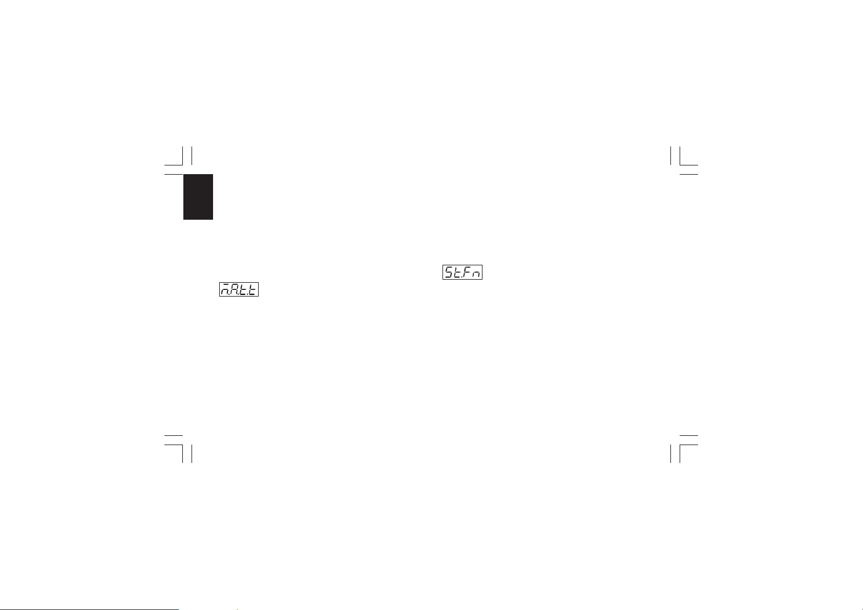
NOTESNOTES
NOTES:
NOTESNOTES
1) When open loop servomotor control drive without valve
position indication is configured, this parameter is forced to
CnF. 4CnF. 4
CnF. 4CnF. 4
CnF. 4
“buñ.” and it cannot be modified.
2) When open loop servomotor control drive with valve position
indication is configured and the transfer from AUTO to MAN
is required, the instrument is able to reach the value
programmed by this parameter using temporarily the valve
position value as a feedback.
- MANUAL to AUTO transfer type - [C.G05]- MANUAL to AUTO transfer type - [C.G05]
- MANUAL to AUTO transfer type - [C.G05]
- MANUAL to AUTO transfer type - [C.G05]- MANUAL to AUTO transfer type - [C.G05]
This parameter will be available only when at least one control
output is configured and manual function is enabled (“ñAn.F”
[C.G03] = “Enb”)
Range: buñ. = Bumpless balance transfer.
buñ.b = Bumpless balanceless transfer (the operative
set point is aligned to the measure value).
NOTESNOTES
NOTES:
NOTESNOTES
1) The “alignment” is not performed if measure is in error
condition or Remote Set point is selected.
2) The selected local set point will be changed even if it is
software protected.
XKP-1-D1.pmd 25/05/2006, 11.2850
General note about the instrument restartingGeneral note about the instrument restarting
General note about the instrument restarting
General note about the instrument restartingGeneral note about the instrument restarting
The two following parameters are used to set the instrument
restarting after a power down:
- the St.Pr [C.G07] parameter setting is used to the instrument
restart when a program was running.
- the St.Fn [C.G06] parameter setting is used to all the other
cases.
- Device status at start up when it works as- Device status at start up when it works as
- Device status at start up when it works as
- Device status at start up when it works as- Device status at start up when it works as
controller - [C.G06]controller - [C.G06]
controller - [C.G06]
controller - [C.G06]controller - [C.G06]
This parameter will be available only when at least one control
output is configured and manual function is enabled (“ñAn.F”
[C.G03] = “Enb”).
Range:Auto = It starts always in auto mode
ñan = It starts always in manual mode with power
output set to 0.
Cnd.A =It starts in the same way it was left prior to
power shut down (if in manual mode the power
output is set to 0).
Cnd.b =It starts in the same way it was left prior to
power shut down (if in manual mode the power
output will be equal to the last value prior to
power shut down).
50
Page 55
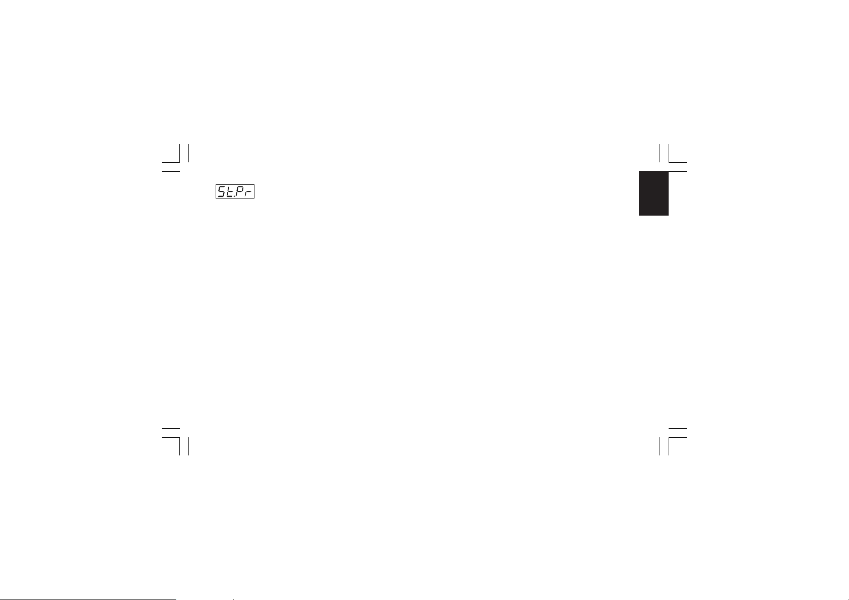
- Program restarting after a power failure- Program restarting after a power failure
- Program restarting after a power failure
- Program restarting after a power failure- Program restarting after a power failure
- [C.G07]- [C.G07]
- [C.G07]
- [C.G07]- [C.G07]
Range:Edit = the program execution will be stopped and the
instrument starts in STAND-BY mode with the
values programmed by [r.A13] to [r.A17] for the
specific program.
SAñE =the program starts from the point in execution
left prior to power shut down.
Src = at power up, the instrument operates as
follows
A ) if the measured value is inner to the
program restart tracking band ("St.tk"
[C.G08]) and the instrument was performing
a soak, the intrument verifies the tracking
band selected for the specific segment and:
A.1) if the measured value is inner to the
specific tracking band, the program
starts from the point in execution left
prior to power shut down.
A.2) if the measured value is outer to the
specific tracking band, the program will
operate as described at point B).
B ) if the measured value is inner to the program
restart tracking band ("St.tk" [C.G08]), and
the instrument was performing a ramp, it will
start to search, in the part of the program
XKP-1-D1.pmd 25/05/2006, 11.2851
already executed, the first set point equal to
the current measured value and
B.1) if this point has been found, the
program execution restart from it.
B.2) if this point has not been found, the
program execution will be stopped and
the instrument starts in STAND-BY mode
with the values programmed by the parameters from "At the end of program x
reset the break event" [r.A13] to "PID
group at the end of program x" [r.A17] for
the specific program.
C ) if the current measured value is outer to the
program restart tracking band ("St.tk" [C.G08]),
the program execution will be stopped and the
instrument starts in STAND-BY mode with the
values programmed by the parameters from
"At the end of program x reset the break
event" [r.A13] to "PID group at the end of
program x" [r.A17] for the specific program.
NOTENOTE
NOTE: When during a program execution, a power failure
NOTENOTE
occurs, at power up the instrument displays this situation
showing on the upper display "E.600" indication.
Push one pusbutton to delete the "E.600" indication.
51
CnF. 4CnF. 4
CnF. 4CnF. 4
CnF. 4
Page 56
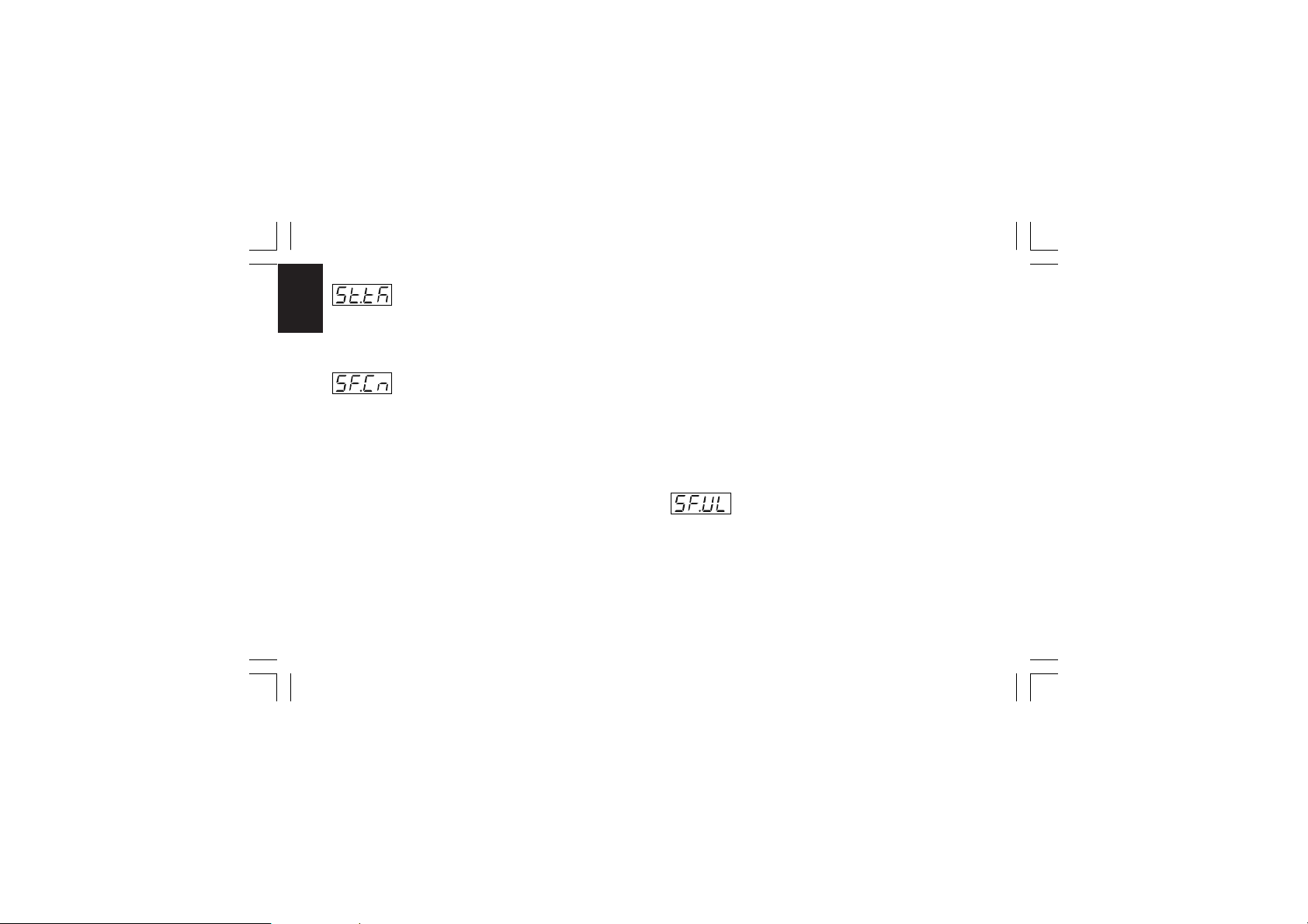
- Program restart tracking band - [C.G08]- Program restart tracking band - [C.G08]
- Program restart tracking band - [C.G08]
- Program restart tracking band - [C.G08]- Program restart tracking band - [C.G08]
This parameter will be available only when "St.Pr" (program
CnF. 5CnF. 5
CnF. 5CnF. 5
CnF. 4CnF. 4
CnF. 4CnF. 4
CnF. 5
CnF. 4
restart after power supply failure [C.G07]) is equal to “Src”.
Range:from 0 to 500 digits.
- Condition for output safety value - [C.G09]- Condition for output safety value - [C.G09]
- Condition for output safety value - [C.G09]
- Condition for output safety value - [C.G09]- Condition for output safety value - [C.G09]
This parameter will be available only when at least one control
output is configured.
Ranges:
- When no output is configured as open loop servomotor
control, "SF.Cn" can be set as follows:
Std. = No safety value (“standard setting” see chapter
ERROR MESSAGES).
Ov.Un= Safety value applied when the instrument
detects an overrange or underrange condition
of the main input.
OvEr = Safety value applied when the instrument detects
an overrange condition of the main input.
Undr = Safety value applied when the instrument
detects an underrange condition of the main
input.
XKP-1-D1.pmd 25/05/2006, 11.2852
- When the open loop servomotor control is configured,
"SF.Cn" can be set as follows:
Std. = No safety value (“standard setting” see chapter
ERROR MESSAGES).
Cnd.A = When the instrument detects an overrange or
underrange condition of the main input, the
servomotor is driven to its high limit position.
Cnd.b = When the instrument detects an overrange or
underrange condition of the main input, the
servomotor is driven to its low limit position.
Cnd.C= When the instrument detects an overrange or
underrange condition of the main input, the
action on servomotor is the complement of
“standard” setting.
- Output safety value - [C.G10]- Output safety value - [C.G10]
- Output safety value - [C.G10]
- Output safety value - [C.G10]- Output safety value - [C.G10]
This parameter will be available only when "SF.Cn" [C.G09] is
equal to “Ov.Un”, “OvEr” or “Undr”.
Range:
- from 0.0 % to 100.0 % if device is configured with one
control output;
- from -100.0 % to 100.0 % if device is configured with two
control outputs (split range excluded).
52
Page 57
CONFIGURATION GROUP 5 [C.Hxx]CONFIGURATION GROUP 5 [C.Hxx]
CONFIGURATION GROUP 5 [C.Hxx]
CONFIGURATION GROUP 5 [C.Hxx]CONFIGURATION GROUP 5 [C.Hxx]
DIGITAL INPUT/OUTPUT CONFIGURATION
- Logic input "DIG 1" function - [C.H01]- Logic input "DIG 1" function - [C.H01]
- Logic input "DIG 1" function - [C.H01]
- Logic input "DIG 1" function - [C.H01]- Logic input "DIG 1" function - [C.H01]
This parameter will be available only when input contact option
is fitted.
Range:nonE = Input contact not used
ru.SL = Input contact used for RUN /HOLD selection.
The status is related to the input level (RUN
when the logic level is "1").
NOTENOTE
NOTE: when an input is programmed as RUN/
NOTENOTE
HOLD selector related with the status, the
RUN/HOLD selection by keyboard has no
effect.
ru.St = Input contact used for RUN /HOLD selection.
The instrument toggles from one status to the
other one when the transition selected by
"d1.St" [C.H02] is detected.
XKP-1-D1.pmd 25/05/2006, 11.2853
NOTE:NOTE:
NOTE: for more details about the RUN/HOLD
NOTE:NOTE:
selection, see the related note at pag.54.
Pr.Ab = Input contact used for program abort (Abort
when the logic level is equal to "1").
NOTENOTE
NOTE: for ABORT function only, the input
NOTENOTE
status must be maintained for more than 3
seconds.
Pr.SL = Input contact used for program selection (for
more details see note 2).
Au.ñA = Input contact used for Auto/Manual selection
(Manual when logic level is “1”)
O.LIñ = Input contact used for output limiter activation
(Output limited when logic level is “1”)
ñ.rSt = Input contact used to reset (acknowledge)
alarm (Reset when logic level is “1”)
rE.dr = Input contact used for Reverse/Direct control
action selection (Direct when logic level is “1”)
NOTENOTE
NOTE: When logic input circuits are not mounted the middle
NOTENOTE
display will show “no.Pr” (not present).
53
CnF. 5CnF. 5
CnF. 5CnF. 5
CnF. 5
Page 58
Notes about logic inputs used for program selectionNotes about logic inputs used for program selection
Notes about logic inputs used for program selection
Notes about logic inputs used for program selectionNotes about logic inputs used for program selection
1) When some logic inputs are programmed as program
selectors ("Pr.SL") the instrument will use these logic inputs
CnF. 5CnF. 5
CnF. 5CnF. 5
CnF. 5
as a binary code.
In the sequence from DIG 1 to 3 and IN 1 to IN 8 the
instrument will considers the first logic input, programmed as
program selector, as the less significant bit while it will
consider the other inputs with increasing order.
For example:
DIG 2, DIG 3, IN 3, IN 7 and IN 8 are programmed as
program selectors. The DIG 2 is the less significant bit while
IN 8 in the most significant bit.
The weight of these 5 inputs is the following:
IN 8 IN 7 IN 3 DIG 3 DIG 2
4
3
2
1
2
2
2
2
0
2
168421
2) If the program number 0 or a program number higher than
99 (90 simple programs + 9 linked programs) is selected, the
instrument will ignore the program selection made by logic
inputs and it allows to make the program selection by
keyboard or by serial link.
3) If a not existing program (a program from 1 to 99) is selected by
logic inputs, the instrument will use the selection made by logic
input and it will inhibit the selection made by keyboard or serial
link but the RUN request will not produce any effect.
XKP-1-D1.pmd 25/05/2006, 11.2854
4) A changement on the program selectors status has effect
only at the next RUN request.
Notes about logic inputs used for RUN/HOLD selectionNotes about logic inputs used for RUN/HOLD selection
Notes about logic inputs used for RUN/HOLD selection
Notes about logic inputs used for RUN/HOLD selectionNotes about logic inputs used for RUN/HOLD selection
At power up the instrument can start (see also "St.Fn" [C.G06]
and "St.Pr" [C.G07] parameters):
1) in manual mode
In this mode the RUN/HOLD logic input has no effect.
2) in stand-by mode
2.a) If "ru.SL" is selected, the RUN/HOLD logic input status
has no effect and the program will start when the
instrument detects the transition from the logic level 0 to
1 (from HOLD to RUN)
2.b) If "ru.St" is selected, the program will start when the
instrument detects the transition programmed by
"d1.St" [C.H02] parameter.
3) in RUN mode
3.a) If "ru.SL" is selected, the RUN/HOLD logic input status
defines the instrument status (logic level 0 for HOLD
and logic level 1 for RUN)
3.b) If "ru.St" is selected, the program starts in the same
way it was left prior to power shut down (HOLD or
RUN).
NOTENOTE
NOTE: When the transfert from controller to programmer mode
NOTENOTE
is performed, the instrument starts in stand by status.
54
Page 59
- Logic input DIG1 - contact status - [C.H02]- Logic input DIG1 - contact status - [C.H02]
- Logic input DIG1 - contact status - [C.H02]
- Logic input DIG1 - contact status - [C.H02]- Logic input DIG1 - contact status - [C.H02]
This parameter will be available only when "d1.Fn" [C.H01] is
different from “nonE”.
Range: CLSd = The input is at logic level “1” when contact is
closed.
When "d1.Fn" [C.H01] is equal to “ru.St”, the
instrument toggles from one status to the other
one when the transition from contact open to
contact close is detected.
OPEn = The input is at logic level “1” when contact is
open.
When "d1.Fn" [C.H01] is equal to “ru.St”, the
instrument toggles from one status to the other
one when the transition from contact close to
contact open is detected.
- Logic input DIG 2 function - [C.H03]- Logic input DIG 2 function - [C.H03]
- Logic input DIG 2 function - [C.H03]
- Logic input DIG 2 function - [C.H03]- Logic input DIG 2 function - [C.H03]
This parameter will be available only when input contact option
is fitted.
Range:nonE = Input contact not used
ru.SL = Input contact used for RUN /HOLD selection.
The status is related to the input level (RUN
when the logic level is "1").
XKP-1-D1.pmd 25/05/2006, 11.2855
NOTENOTE
NOTE: when an input is programmed as RUN/
NOTENOTE
HOLD selector related with the status, the RUN/
HOLD selection by keyboard has no effect.
ru.St = Input contact used for RUN /HOLD selection.
CnF. 5CnF. 5
CnF. 5CnF. 5
CnF. 5
The instrument toggles from one status to the
other one when the transition selected by
"d2.St" [C.H04] is detected.
NOTE:NOTE:
NOTE: for more details about the RUN/HOLD
NOTE:NOTE:
selection, see the related note at pag.54.
Pr.Ab = Input contact used for program abort (Abort
when the logic level is equal to "1").
NOTENOTE
NOTE: for ABORT function only, the input
NOTENOTE
status must be maintained for more than 3
seconds.
Pr.SL = Input contact used for program selection (for
more details see NOTE 2) of the "d1.Fn"
("Logic input 1 function" [C.H01]) parameter).
Au.ñA = Input contact used for Auto/Manual selection
(Manual when logic level is “1”)
O.LIñ = Input contact used for output limiter activation
(Output limited when logic level is “1”)
ñ.rSt = Input contact used to reset (acknowledge)
alarm (Reset when logic level is “1”)
rE.dr = Input contact used for Reverse/Direct control
action selection (Direct when logic level is “1”)
55
Page 60
NOTENOTE
NOTE: See also all NOTES of the "d1.Fn" ("Logic input 1
NOTENOTE
function" [C.H01]) parameter.
CnF. 5CnF. 5
CnF. 5CnF. 5
CnF. 5
- Logic input DIG 2 - contact status - [C.H04]- Logic input DIG 2 - contact status - [C.H04]
- Logic input DIG 2 - contact status - [C.H04]
- Logic input DIG 2 - contact status - [C.H04]- Logic input DIG 2 - contact status - [C.H04]
This parameter will be available only when "d2.Fn" [C.H03] is
different from “nonE”.
Range: CLSd = The input is at logic level “1” when contact is
closed.
When "d2.Fn" [C.H03] is equal to “ru.St”, the
instrument toggles from one status to the other
one when the transition from contact open to
contact close is detected.
OPEn = The input is at logic level “1” when contact is
open.
When "d2.Fn" [C.H03] is equal to “ru.St”, the
instrument toggles from one status to the other
one when the transition from contact close to
contact open is detected.
XKP-1-D1.pmd 25/05/2006, 11.2856
- Logic input DIG 3 function - [C.H05]- Logic input DIG 3 function - [C.H05]
- Logic input DIG 3 function - [C.H05]
- Logic input DIG 3 function - [C.H05]- Logic input DIG 3 function - [C.H05]
This parameter will be available only when input contact option
is fitted.
Range:nonE = Input contact not used
ru.SL = Input contact used for RUN /HOLD selection.
The status is related to the input level (RUN
when the logic level is "1").
NOTENOTE
NOTE: when an input is programmed as RUN/
NOTENOTE
HOLD selector related with the status, the RUN/
HOLD selection by keyboard has no effect.
ru.St = Input contact used for RUN /HOLD selection.
The instrument toggles from one status to the
other one when the transition selected by
"d3.St" [C.H06] is detected.
NOTE:NOTE:
NOTE: for more details about the RUN/HOLD
NOTE:NOTE:
selection, see the related note at pag.54.
Pr.Ab = Input contact used for program abort (Abort
when the logic level is equal to "1").
NOTENOTE
NOTE: for ABORT function only, the input
NOTENOTE
status must be maintained for more than 3
seconds.
Pr.SL = Input contact used for program selection (for
more details see NOTE 2) of the "d1.Fn"
("Logic input 1 function" [C.H01]) parameter).
56
Page 61
Au.ñA = Input contact used for Auto/Manual selection
(Manual when logic level is “1”)
O.LIñ = Input contact used for output limiter activation
(Output limited when logic level is “1”)
ñ.rSt = Input contact used to reset (acknowledge)
alarm (Reset when logic level is “1”)
rE.dr = Input contact used for Reverse/Direct control
action selection (Direct when logic level is “1”)
NOTENOTE
NOTE: See also all NOTES of the "d1.Fn" ("Logic input 1
NOTENOTE
function" [C.H01]) parameter.
- Logic input DIG 3 - contact status - [C.H06]- Logic input DIG 3 - contact status - [C.H06]
- Logic input DIG 3 - contact status - [C.H06]
- Logic input DIG 3 - contact status - [C.H06]- Logic input DIG 3 - contact status - [C.H06]
This parameter will be available only when "d3.Fn" [C.H05] is
different from “nonE”.
Range: CLSd = The input is at logic level “1” when contact is
closed.
When "d3.Fn" [C.H05] is equal to “ru.St”, the
instrument toggles from one status to the other
one when the transition from contact open to
contact close is detected.
OPEn = The input is at logic level “1” when contact is
open.
XKP-1-D1.pmd 25/05/2006, 11.2857
When "d3.Fn" [C.H05] is equal to “ru.St”, the
instrument toggles from one status to the other
one when the transition from contact close to
contact open is detected.
- Logic input IN 1 function - [C.H07]- Logic input IN 1 function - [C.H07]
- Logic input IN 1 function - [C.H07]
- Logic input IN 1 function - [C.H07]- Logic input IN 1 function - [C.H07]
This parameter will be available only when additional input
contact option is fitted.
Range:nonE = Input contact not used
ru.SL = Input contact used for RUN /HOLD selection.
The status is related to the input level (RUN
when the logic level is "1").
NOTENOTE
NOTE: when an input is programmed as RUN/
NOTENOTE
HOLD selector related with the status, the RUN/
HOLD selection by keyboard has no effect.
ru.St = Input contact used for RUN /HOLD selection.
The instrument toggles from one status to the
other one when the transition selected by
"I1.St" [C.H08] is detected.
NOTE:NOTE:
NOTE: for more details about the RUN/HOLD
NOTE:NOTE:
selection, see the related note at pag.54.
Pr.Ab = Input contact used for program abort (Abort
when the logic level is equal to "1").
57
CnF. 5CnF. 5
CnF. 5CnF. 5
CnF. 5
Page 62
NOTENOTE
NOTE: for ABORT function only, the input
NOTENOTE
status must be maintained for more than 3
CnF. 5CnF. 5
CnF. 5CnF. 5
CnF. 5
seconds.
Pr.SL = Input contact used for program selection (for
more details see NOTE 2) of the "d1.Fn"
("Logic input 1 function" [C.H01]) parameter).
NOTENOTE
NOTE: See also all NOTES of the "d1.Fn" ("Logic input 1
NOTENOTE
function" [C.H01]) parameter.
- Logic input IN 1 - contact status - [C.H08]- Logic input IN 1 - contact status - [C.H08]
- Logic input IN 1 - contact status - [C.H08]
- Logic input IN 1 - contact status - [C.H08]- Logic input IN 1 - contact status - [C.H08]
This parameter will be available only when "I1.Fn" [C.H07] is
different from “nonE”.
Range: CLSd = The input is at logic level “1” when contact is
closed.
When "I1.Fn" [C.H07] is equal to “ru.St”, the
instrument toggles from one status to the other
one when the transition from contact open to
contact close is detected.
OPEn = The input is at logic level “1” when contact is
open.
When "I1.Fn" [C.H07] is equal to “ru.St”, the
instrument toggles from one status to the other
XKP-1-D1.pmd 25/05/2006, 11.2858
one when the transition from contact close to
contact open is detected.
The steps C.H07 and C.H08 can be repeated for all theThe steps C.H07 and C.H08 can be repeated for all the
The steps C.H07 and C.H08 can be repeated for all the
The steps C.H07 and C.H08 can be repeated for all theThe steps C.H07 and C.H08 can be repeated for all the
fitted logic input (from IN 2 to IN 8).fitted logic input (from IN 2 to IN 8).
fitted logic input (from IN 2 to IN 8).
fitted logic input (from IN 2 to IN 8).fitted logic input (from IN 2 to IN 8).
- Event 1 function - [C.H09]- Event 1 function - [C.H09]
- Event 1 function - [C.H09]
- Event 1 function - [C.H09]- Event 1 function - [C.H09]
This parameter will be available only when OUT 1 is configured
as event annunciator ("O1.Fn" [C.E01] is equal to “Eun.1”).
Range:nonE = Event not used (for Events from 10 to 19 only)
brk.E = Break event
TIñ.E =Timer event
At the power ON, after a power supply failure,
the timer event continues from the same point
it was prior to the power failure.
End.c = End of cycle annunciator.
At the end of every cycle, the instrument forces
the output programmed as "end of cycle
annunciator" in ON status for a time equal to
the value assigned to "tE.cY" [C.H11]
parameter.
End.P = End of profile annunciator.
At the end of the profile, the instrument forces
58
Page 63
the output programmed as "end of profile
annunciator" in ON status for a time equal to
the value assigned to "tE.Pr" [C.H12]
parameter.
run = Program in run mode annunciator (Logic level
“1” during the run mode).
wait = Program in wait state annunciator (Logic level
“1” when the program is in wait state)
HOld = Program in hold state annunciator (Logic level
“1” when the program is in hold state)
O.P.O.=Device in Output Power OFF state (Logic level
"1" when the instrument is in "Output Power
OFF" state)
ñ.In.E =Error condition (Over-Under-Open-Shrt) on
main input (Logic level “1” when error occurs)
Cj.Er = Error condition on CJ measurement (Logic
level “1” when error occurs)
A.In.E= Error condition (Over-Under-Open) on auxiliary
input (Logic level “1” when error occurs)
ñEA.E = Error condition on main, secondary or CJ
inputs (Logic level “1” when error occurs)
Au.ñA =Auto/manual mode annunciator (Logic level “1”
when device is in manual mode)
XKP-1-D1.pmd 25/05/2006, 11.2859
- Event 1 contact status - [C.H10]- Event 1 contact status - [C.H10]
- Event 1 contact status - [C.H10]
- Event 1 contact status - [C.H10]- Event 1 contact status - [C.H10]
This parameter will be available only when OUT 1 is configured
as event annunciator ("O1.Fn" [C.E01] is equal to “Eun.1”) or
the Event 1 is programmed as Timer event or break event.
Range: CLSd = The output is at logic level “1” when contact is
closed
OPEn = The output is at logic level “1” when contact is
open
The steps C.H09 and C.H10 can be repeated for all theThe steps C.H09 and C.H10 can be repeated for all the
The steps C.H09 and C.H10 can be repeated for all the
The steps C.H09 and C.H10 can be repeated for all theThe steps C.H09 and C.H10 can be repeated for all the
selected event (from "Event 2" to "Event 4") and for theselected event (from "Event 2" to "Event 4") and for the
selected event (from "Event 2" to "Event 4") and for the
selected event (from "Event 2" to "Event 4") and for theselected event (from "Event 2" to "Event 4") and for the
auxiliary outputs (from "Event 10" to "Event 19").auxiliary outputs (from "Event 10" to "Event 19").
auxiliary outputs (from "Event 10" to "Event 19").
auxiliary outputs (from "Event 10" to "Event 19").auxiliary outputs (from "Event 10" to "Event 19").
NOTE: when the auxiliary output hardware is fitted theNOTE: when the auxiliary output hardware is fitted the
NOTE: when the auxiliary output hardware is fitted the
NOTE: when the auxiliary output hardware is fitted theNOTE: when the auxiliary output hardware is fitted the
parameters related with "Event 10" to "Event 19" are everparameters related with "Event 10" to "Event 19" are ever
parameters related with "Event 10" to "Event 19" are ever
parameters related with "Event 10" to "Event 19" are everparameters related with "Event 10" to "Event 19" are ever
available.available.
available.
available.available.
59
CnF. 5CnF. 5
CnF. 5CnF. 5
CnF. 5
Page 64
- Time for the "End of cycle" annunciator- Time for the "End of cycle" annunciator
- Time for the "End of cycle" annunciator
- Time for the "End of cycle" annunciator- Time for the "End of cycle" annunciator
- [C.H11]- [C.H11]
- [C.H11]
Available only when one of the Events is programmed as "End
CnF. 6CnF. 6
CnF. 6CnF. 6
CnF. 6
CnF. 5CnF. 5
CnF. 5CnF. 5
CnF. 5
of cycle" annunciator.
- [C.H11]- [C.H11]
Range: from 0 to 240 s.
- Time for the "End of profile" annunciator- Time for the "End of profile" annunciator
- Time for the "End of profile" annunciator
- Time for the "End of profile" annunciator- Time for the "End of profile" annunciator
- [C.H12]- [C.H12]
- [C.H12]
- [C.H12]- [C.H12]
Available only when one of the Events is programmed as "End
of profile" annunciator.
Range: from 0 to 240 s. Above this limit, the display will show
"InF" and, at the end of the last programmed
cycle, the Event output is forced in ON
condition until a new RUN command is
detected.
XKP-1-D1.pmd 25/05/2006, 11.2860
General notes about configuration group 5General notes about configuration group 5
General notes about configuration group 5
General notes about configuration group 5General notes about configuration group 5
1) Digital input function selection should be “consistent” with other
configuration parameters otherwise this digital input will remain
unused.
2) Changing menu the device will check that the same function is
not assigned to more than one digital input (exception made for
digital inputs used for program selection), otherwise the display
will show:
Pushing the FUNC pushbutton, verify (and modify when
necessary) all the group 5 configuration parameters in order
to satisfy the previously described condition.
60
Page 65
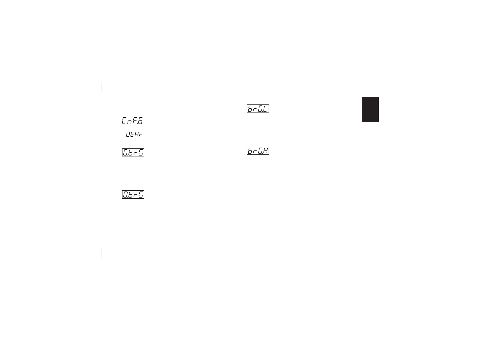
CONFIGURATION GROUP 6 [C.Ixx]CONFIGURATION GROUP 6 [C.Ixx]
CONFIGURATION GROUP 6 [C.Ixx]
CONFIGURATION GROUP 6 [C.Ixx]CONFIGURATION GROUP 6 [C.Ixx]
OTHER CONFIGURATION PARAMETERS
- Green bargraph function - [C.I01]- Green bargraph function - [C.I01]
- Green bargraph function - [C.I01]
- Green bargraph function - [C.I01]- Green bargraph function - [C.I01]
This parameter will be available for MKP models only.
Range:Pr.Ur =the green bargraph will show the process
variable value.
DEV. = the green bargraph will show the deviation
(measured value minus set point).
- Orange bargraph function - [C.I02]- Orange bargraph function - [C.I02]
- Orange bargraph function - [C.I02]
- Orange bargraph function - [C.I02]- Orange bargraph function - [C.I02]
This parameter will be available for MKP models only.
Range:OP.SP= On bargraph is shown the operative set point
value.
P.Out. = On bargraph is shown the process output
value.
XKP-1-D1.pmd 25/05/2006, 11.2861
- Bargraph initial scale value - [C.I03]- Bargraph initial scale value - [C.I03]
- Bargraph initial scale value - [C.I03]
- Bargraph initial scale value - [C.I03]- Bargraph initial scale value - [C.I03]
This parameter will be available only for MKP models when
“G.brG” [C.I01] is equal to “Pr.Ur” and/or “O.brG” [C.I02] is
equal to “OP.SP”.
Range: From “ñ.In.L” ("Read-out initial scale value" [C.d05]) to
“ñ.In.H” ("Read-out full scale value [C.d06])
- Bargraph full scale value - [C.I04]- Bargraph full scale value - [C.I04]
- Bargraph full scale value - [C.I04]
- Bargraph full scale value - [C.I04]- Bargraph full scale value - [C.I04]
This parameter will be available only for MKP models when
“G.brG” [C.I01] is equal to “Pr.Ur” and/or “O.brG” [C.I02] is
equal to “OP.SP”.
Range: From “ñ.In.L” ("Read-out initial scale value" [C.d05]) to
“ñ.In.H” ("Read-out full scale value [C.d06])
61
CnF. 6CnF. 6
CnF. 6CnF. 6
CnF. 6
Page 66
- Resolution of the deviation bargraph - [C.I05]- Resolution of the deviation bargraph - [C.I05]
- Resolution of the deviation bargraph - [C.I05]
- Resolution of the deviation bargraph - [C.I05]- Resolution of the deviation bargraph - [C.I05]
This parameter will be available only for MKP models when
CnF. 6CnF. 6
CnF. 6CnF. 6
CnF. 6
“G.brG” [C.I01] is equal to “DEV.”.
Range: 1-2-5-10-20 or 50 = Digits per segment
- Operative set point alignment at start up- Operative set point alignment at start up
- Operative set point alignment at start up
- Operative set point alignment at start up- Operative set point alignment at start up
- [C.I06]- [C.I06]
- [C.I06]
- [C.I06]- [C.I06]
Range:ALG = At start up the operative set point is aligned to
measured value and then it will reach the
selected set point with the programmed ramp
(“Grd1” [r.E14] and “Grd2” [r.E15]).
n.ALG = At start up the operative set point is equal to
the selected set point
NOTESNOTES
NOTES:
NOTESNOTES
1) The “ALG” selection has no effect when the measure is in
error condition.
2) If instrument shutdown has been made during program
execution, the SP.AL parameter has no effect and the
instrument behaviour is related only to the selection of St.Pr
(program restart after power failure [C.G07]) parameter.
XKP-1-D1.pmd 25/05/2006, 11.2862
- Set point display type - [C.I07]- Set point display type - [C.I07]
- Set point display type - [C.I07]
- Set point display type - [C.I07]- Set point display type - [C.I07]
This selection has effect only when the instrument operates as
controller.
Range: Fn.SP= When device is in normal display mode and it
is performing a set point ramp, the middle
display will show the final set point value.
OP.SP=When device is in normal display mode and it
is performing a set point ramp, the middle
display will show the operative set point value.
62
Page 67
- Servomotor behaviour when the output- Servomotor behaviour when the output
- Servomotor behaviour when the output
- Servomotor behaviour when the output- Servomotor behaviour when the output
power is limited - [C.I08]power is limited - [C.I08]
power is limited - [C.I08]
power is limited - [C.I08]power is limited - [C.I08]
This parameter will be available only when the close loop
servomotor control drive is configured
Range:bAL =When the PID output reaches the specific
output limits ("Main control output low limit"
[r.E04] or "Main control output high limit"
[r.E05] or "Secondary control output low limit"
[r.E08] or "Secondary control output high limit"
[r.E09]) the instrument will reach the respective
limit and than it will maintain the output relay in
open condition.
n.bAL = When PID value is higher than "Main control
output high limit" [r.E05] or "Secondary control
output high limit" [r.E09] the OUT 3 () relay
contact is ever closed.
When PID value is lower than "Main control
output low limit" [r.E04] or "Secondary control
output low limit" [r.E08] the OUT 4 () relay
contact is ever closed.
XKP-1-D1.pmd 25/05/2006, 11.2863
- Input threshold to enable the soft start- Input threshold to enable the soft start
- Input threshold to enable the soft start
- Input threshold to enable the soft start- Input threshold to enable the soft start
- [C.I09]- [C.I09]
- [C.I09]
- [C.I09]- [C.I09]
Range:for TC/RTD ranges - within the input range;
for linear input - within “ñ.In.L” ("Read-out initial scale
value" [C.d05]) and ”ñ.In.H” ("Read-out full
scale value" [C.d06]).
NOTENOTE
NOTE: At start up if the measured value is lower than threshold
NOTENOTE
value, the device maintains the output power limiting (”ñ.OLL”
[r.E04], ”ñ.OLH” [r.E05], ”S.OLL” [r.E08] and ”S.OLH” [r.E09])
for a programmed time (“tOL” [rE.16]).
This function is called “soft start”
This threshold value has no effect if “tOL” [rE.16] = InF or when
one logic input is configured for output limiter activation.
- Time out selection - [C.I10]- Time out selection - [C.I10]
- Time out selection - [C.I10]
- Time out selection - [C.I10]- Time out selection - [C.I10]
Range: tñ.10 = 10s time out
tñ.30 = 30s time out
NOTENOTE
NOTE: for more details see "NOTE 2" at page 28.
NOTENOTE
63
CnF. 6CnF. 6
CnF. 6CnF. 6
CnF. 6
Page 68
- Out failure detection (OFD) - [C.I11]- Out failure detection (OFD) - [C.I11]
- Out failure detection (OFD) - [C.I11]
- Out failure detection (OFD) - [C.I11]- Out failure detection (OFD) - [C.I11]
This parameter will be available only when the option is fitted
CnF. 6CnF. 6
CnF. 6CnF. 6
CnF. 6
and the main and/or the secondary output is configured as time
proportional control output
Range:nonE = Function not used
ñC.On = Set “Fd.Fn” to “ñC.On” when the load under
test is energized during the ON status of the
main output (relay energized or SSR output
status 1).
ñC.OF= Set “Fd.Fn” to “ñC.OF” when the load under
test is energized during the OFF status of the
main output (relay de-energized or SSR output
status 0).
SC.On= Set “Fd.Fn” to “SC.On” when the load under test
is energized during the ON status of the secondary output (relay energized or SSR output status
1).
SC.OF= Set “Fd.Fn” to “SC.OF” when the load under test
is energized during the OFF status of the secondary output (relay de-energized or SSR output
status 0).
NOTENOTE
NOTE: When the option is not fitted the middle display will
NOTENOTE
show “no.Pr”
XKP-1-D1.pmd 25/05/2006, 11.2864
- Primary current of the current transformer- Primary current of the current transformer
- Primary current of the current transformer
- Primary current of the current transformer- Primary current of the current transformer
- [C.I12]- [C.I12]
- [C.I12]
- [C.I12]- [C.I12]
This parameter will be available only when “Fd.Fn” [C.I11] is
different from “nonE”
Range: From 10 A to 100 A
- Out failure detection - output assignment- Out failure detection - output assignment
- Out failure detection - output assignment
- Out failure detection - output assignment- Out failure detection - output assignment
- C.I13- C.I13
- C.I13
- C.I13- C.I13
This parameter will be available only when “Fd.Fn” [C.I11] is
different from “nonE”
Range:nonE = The "Out failure detection" alarm is signalled
only on display
OUt.1 = The "Out failure detection" alarm is signalled
on OUT 1
OUt.2 = The "Out failure detection" alarm is signalled
on OUT 2
OUt.3 = The "Out failure detection" alarm is signalled
on OUT 3
OUt.4 = The "Out failure detection" alarm is signalled
on OUT 4
NOTENOTE
NOTE: "Out failure detection "alarm annunciator cannot be
NOTENOTE
assigned to an output already configured as control output.
64
Page 69
- Automatic start enabling - [C.I14]- Automatic start enabling - [C.I14]
- Automatic start enabling - [C.I14]
- Automatic start enabling - [C.I14]- Automatic start enabling - [C.I14]
This parameter will be available only when the clock calendar
hardware is mounted.
Range:nonE = The "Automatic start" function is disabled
Cnd.A = the program will start at the programmed time
only if the following conditions are satisfied:
- no other program is running
- no power down is present when the current
time coincides with the programmed start
time;
- when a logic input is programmed for RUN/
HOLD function related input level, the input
level must be "1";
- the instrument isn’t in manual mode.
Cnd.b = at the programmed start time the instrument
verify the above described conditions and, if
one or more conditions are not satisfied, the
instrument will continue to verify it for the
programmed hysteresis time.
If the wrong condition disappeares during the
hysteresis time, the instrument will start the
selected program otherwise it does not start
any program.
XKP-1-D1.pmd 25/05/2006, 11.2865
- Hysteresis of the Automatic starting - [C.I15]- Hysteresis of the Automatic starting - [C.I15]
- Hysteresis of the Automatic starting - [C.I15]
- Hysteresis of the Automatic starting - [C.I15]- Hysteresis of the Automatic starting - [C.I15]
This parameter will be available only when the clock calendar
hardware is mounted and the "En.Ck" [C.I.14] parameter is set
to "Cnd.b".
Range:from 0.01 (hh.mm) to 6.00 (hh.mm).
- Current time - [C.I16]- Current time - [C.I16]
- Current time - [C.I16]
- Current time - [C.I16]- Current time - [C.I16]
This parameter will be available only when the clock calendar
hardware is mounted and the "En.Ck" [C.I.14] parameter is
different from "nonE".
Range:from 0.00 (hh.mm) to 23.59 (hh.mm).
65
CnF. 6CnF. 6
CnF. 6CnF. 6
CnF. 6
Page 70
- Current day - [C.I17]- Current day - [C.I17]
- Current day - [C.I17]
- Current day - [C.I17]- Current day - [C.I17]
This parameter will be available only when the clock calendar
VErFVErF
VErFVErF
VErF
CnF. 6CnF. 6
CnF. 6CnF. 6
CnF. 6
hardware is mounted and the "En.Ck" [C.I.14] parameter is
different from "nonE".
Range: ñon = Monday
tUe = Tuesday
yE d = Wednesday
tHU = Thursday
Fr i = Friday
SAt = Saturday
Sun = Sunday
XKP-1-D1.pmd 25/05/2006, 11.2866
CONFIGURATION GROUP VERF [C.Lxx]CONFIGURATION GROUP VERF [C.Lxx]
CONFIGURATION GROUP VERF [C.Lxx]
CONFIGURATION GROUP VERF [C.Lxx]CONFIGURATION GROUP VERF [C.Lxx]
CLOCK AND INPUT/OUTPUT TEST
This group is displayed only when configuration modify mode is
enabled.
This group allows to verify the correct working of:
- the clock calendar,
- the relay outputs (OUT 1 up to OUT4),
- digital inputs (diG.1 up to diG.3),
- the auxiliary inputs from In1 up to In8 and the relays of the
auxiliary outputs from OUT10 up to OUT19, if the optional I/O
card is fitted.
When an output is in "On" status, the related LED will light up
66
Page 71
- Clock calendar test - [C.L01]- Clock calendar test - [C.L01]
- Clock calendar test - [C.L01]
- Clock calendar test - [C.L01]- Clock calendar test - [C.L01]
This parameter is available only if the clock calendar option is
fitted.
Middle display: minutes and seconds
NOTE:NOTE:
NOTE: The clock calendar working is identified by the running
NOTE:NOTE:
of the seconds.
- OUT 1 status - [C.L02]- OUT 1 status - [C.L02]
- OUT 1 status - [C.L02]
- OUT 1 status - [C.L02]- OUT 1 status - [C.L02]
Range:On = Output enabled (relay energized)
OF F = Output disabled (relay deenergized)
NOTE:NOTE:
NOTE: By pushing the or key it is possible to change
NOTE:NOTE:
the output state. It is possible to verify the remaining outputs
(OUT 2 up to OUT 4) as described for OUT 1.
- Auxiliary OUT 10 status - [C.L03]- Auxiliary OUT 10 status - [C.L03]
- Auxiliary OUT 10 status - [C.L03]
- Auxiliary OUT 10 status - [C.L03]- Auxiliary OUT 10 status - [C.L03]
This parameter is available only if the optional card is fitted.
Range:On = Output enabled (relay energized)
OF F = Output disabled (relay deenergized)
NOTE:NOTE:
NOTE: By pushing the or key it is possible to change
NOTE:NOTE:
the auxiliary output state. It is possible to verify the remaining
auxiliary outputs (OUT 11 up to OUT 19) as described for
OUT 10.
XKP-1-D1.pmd 25/05/2006, 11.2867
- Digital input dIG.1 status - [C.L04]- Digital input dIG.1 status - [C.L04]
- Digital input dIG.1 status - [C.L04]
- Digital input dIG.1 status - [C.L04]- Digital input dIG.1 status - [C.L04]
Range:Open = Input open
CLSd = Input closed
NOTES:NOTES:
NOTES:
NOTES:NOTES:
1) This is a reading parameter only, it shows the input status.
2) In case of problem, connect the input and the related
common terminals with a copper conductor, if the display
shows "CLSd", the problem is located after the instrument.
3) It is possible to verify the remaining digital inputs (diG2 and
diG3) as described for diG 1.
- Auxiliary input In.1 status - [C.L05]- Auxiliary input In.1 status - [C.L05]
- Auxiliary input In.1 status - [C.L05]
- Auxiliary input In.1 status - [C.L05]- Auxiliary input In.1 status - [C.L05]
This parameter is available only if the optional card is fitted.
Range:Open = Input open
CLSd = Input closed
NOTES:NOTES:
NOTES:
NOTES:NOTES:
1) This is a reading parameter only, it shows the input status.
2) In case of problem, connect the input and the related
common terminals with a copper conductor, if the display
shows "CLSd", the problem is located after the instrument.
3) It is possible to verify the remaining digital inputs (In 2 up to
In 8) as described for In 1.
67
VErFVErF
VErFVErF
VErF
Page 72

General note for configuration group "VErF"General note for configuration group "VErF"
General note for configuration group "VErF"
General note for configuration group "VErF"General note for configuration group "VErF"
Returning in the "run time mode", the instrument restarts to
control the process, the settings performed into this group do
not affect the working settings.
CONFIGURATION GROUP END [C.Mxx]CONFIGURATION GROUP END [C.Mxx]
CONFIGURATION GROUP END [C.Mxx]
CONFIGURATION GROUP END [C.Mxx]CONFIGURATION GROUP END [C.Mxx]
END CONFIGURATION
This group will be displayed only when configuration modify
mode is enabled.
Range:nO = with this selection the instrument comes back
Pushing ”” or “” push-button to select the desired action and
then push “MENU” push-button.
XKP-1-D1.pmd 25/05/2006, 11.2868
to the first display of the configuration modify
mode
YE S = this selection ends the configuration modify
mode; the instrument preforms an automatic
reset and restarts the run time mode.
RUN TIME MODERUN TIME MODE
RUN TIME MODE
RUN TIME MODERUN TIME MODE
PreliminaryPreliminary
Preliminary
PreliminaryPreliminary
If V101 is correctly set (see "Operative mode and hardware
lock" at page 23), and the configuration mode has been
terminated, the instrument will be in run time mode.
During run time mode the instrument performs the loop control
and manages all the instrument functions (SMART, ALARMS,
etc.).
The run time mode is divided in two sub-modes:
- programmer mode (the instrument operates as programmer
- controller mode (the instrument operates as a simple
At power up the instrument will start in the same Sub-mode it
was prior to the power down (controller mode or programmer
mode). The current operative mode is shown by the status of
the PRG LED indicator (ON when the programmer sub-mode is
selected).
68
and common setter)
controller)
Page 73

CONTROL PARAMETERSCONTROL PARAMETERS
CONTROL PARAMETERS
CONTROL PARAMETERSCONTROL PARAMETERS
The run time parameters are common for programmer and for
controller mode (exception made for group P and group 9
available only when the instrument operates in programmer
mode).
CONTROL PARAMETERS PROTECTIONCONTROL PARAMETERS PROTECTION
CONTROL PARAMETERS PROTECTION
CONTROL PARAMETERS PROTECTIONCONTROL PARAMETERS PROTECTION
Moving from one run time parameter group to another, the
instrument will show, at first, the group number (on the upper
display), the mnemonic code (on the lower display) and the
security status (on the middle display) of the group.
The possible security status are:
Enb = the parameters of this group are not protected and they
may be modified;
inh = the parameters of this group are ever protected and
they cannot be modified
KE Y = the parameters of this group are software protected.
In this case, using ““ and “” push-button set a value
equal to the security code programmed during the "Run
time security code " (see page 24) and then push
“FUNC”.
If the programmed value matches the security code,
the parameters of this group can be modified otherwise
they remain protected.
XKP-1-D1.pmd 25/05/2006, 11.2869
ATTENTIONATTENTION
ATTENTION: One software key protects one or more run time
ATTENTIONATTENTION
parameter groups so that when the software key is set, it is
possible to modify the run time parameters of all groups.
The software protection will be automatically restored when the
instrument comes back to the "normal display mode" (by
"MENU" push-button pressure or by the time out).
The parameter monitoring and modification are subjected to a
time out (see “t.out” [C.I10] parameter) after that, the display
returns in “Normal display mode” and the eventual modification
of the last displayed parameter will be lost.
CONTROL PARAMETERS MODIFICATIONCONTROL PARAMETERS MODIFICATION
CONTROL PARAMETERS MODIFICATION
CONTROL PARAMETERS MODIFICATIONCONTROL PARAMETERS MODIFICATION
By “MENU” push-button it is possible to start the run time
parameter modification by selecting desired run time parameter
group.
During the run time parameter modification, the upper display
shows the selected parameter group, the lower display shows
the mnemonic code of the selected parameter while the central
display shows the value or status assigned to the selected
parameter.
69
Page 74

NOTESNOTES
NOTES:
NOTESNOTES
1) In the following pages we will describe all the parameter of
the instrument. The instrument, however, will show only the
parameters related with the specific hardware and in
accordance with the specific instrument configuration.
2) If all the parameters of a group are not available, the
instrument will not display this group.
3) For an easy consultation of this manual, a sheet named
"Reference parameter guide" with all the parameter
visualizations is enclosed.
The groups of run time parameters are identified by the "R"
letter followed by A, B etc.
The "code" formed by the group and the row (i.e. R.A01
Gr. 2Gr. 2
Gr. 2Gr. 2
Gr. 2
where "R.A" is run time group1 and "01" is the row 1) is
reported, in the user manual, before each parameter
description and allows you to quickly find out the respective
parameter.
XKP-1-D1.pmd 25/05/2006, 11.2870
Run time group P [r.Axx]Run time group P [r.Axx]
Run time group P [r.Axx]
Run time group P [r.Axx]Run time group P [r.Axx]
Program editing
This group is available when the instrument operates as
programmer only.
ALL the information about program parameters areALL the information about program parameters are
ALL the information about program parameters are
ALL the information about program parameters areALL the information about program parameters are
reported at paragraph "EDIT mode" at page 114.reported at paragraph "EDIT mode" at page 114.
reported at paragraph "EDIT mode" at page 114.
reported at paragraph "EDIT mode" at page 114.reported at paragraph "EDIT mode" at page 114.
70
Page 75
Run time group 2 [r.bxx]Run time group 2 [r.bxx]
Run time group 2 [r.bxx]
Run time group 2 [r.bxx]Run time group 2 [r.bxx]
COMMAND
- Programmer/controller mode selection- Programmer/controller mode selection
- Programmer/controller mode selection
- Programmer/controller mode selection- Programmer/controller mode selection
- [r.b01]- [r.b01]
- [r.b01]
- [r.b01]- [r.b01]
This parameter can be modified only when no program is
running.
Range: YES= the device will be operative as programmer
nO = the device will be operative as controller
- Main set point - [r.b02]- Main set point - [r.b02]
- Main set point - [r.b02]
- Main set point - [r.b02]- Main set point - [r.b02]
This parameter is available when the instrument is in controller
mode only.
Range:from rL (set point low limit [rE.12]) to rH set point high
limit [rE.13]).
XKP-1-D1.pmd 25/05/2006, 11.2871
- SMART function - [r.b03]- SMART function - [r.b03]
- SMART function - [r.b03]
- SMART function - [r.b03]- SMART function - [r.b03]
This parameter is available when the instrument operates in
controller mode, at least one control output is configured and
SMART function is enabled (“Sñ.Fn” [C.G01]= “Enb”)
Range: OFF = SMART algorithm is deactivated
ON = SMART algorithm is activated
NoteNote
Note: if the transfert from controller to programmer mode is
NoteNote
required when the SMART function is active, the instrument
automatically disables the SMART function.
- Output Power OFF mode - [r.b04]- Output Power OFF mode - [r.b04]
- Output Power OFF mode - [r.b04]
- Output Power OFF mode - [r.b04]- Output Power OFF mode - [r.b04]
This parameter is available only when no program is running.
Range: YES = Output Power OFF mode is active
No = Output Power OFF mode is deactivated
- Program selection for clock start - [r.b05]- Program selection for clock start - [r.b05]
- Program selection for clock start - [r.b05]
- Program selection for clock start - [r.b05]- Program selection for clock start - [r.b05]
This parameter is available when the clock option is fitted and
enabled ("En.Ck" [CI.14] parameter is different from "nonE").
Range: nonE = Clock start disabled
71
Gr. 2Gr. 2
Gr. 2Gr. 2
Gr. 2
Page 76
from 1 to 90= it is the simple program selected for the
clock start.
from L1 to L9= It is the linked program selected for the
clock start.
NOTESNOTES
NOTES:
NOTESNOTES
1) If no program has been created, this parameter will be
forced to "nonE".
2) It is possible to select the already existing programs only.
3) It is not possible to delete a program selected for the clock
start.
- Day of the clock start - [r.b06]- Day of the clock start - [r.b06]
- Day of the clock start - [r.b06]
Gr. 3Gr. 3
Gr. 3Gr. 3
Gr. 2Gr. 2
Gr. 2Gr. 2
Gr. 3
Gr. 2
- Day of the clock start - [r.b06]- Day of the clock start - [r.b06]
This parameter is available when the clock option is fitted,
enabled and activated ("En.Ck" [CI.14] parameter is different
from "nonE" and "Pr.St" [rb.05] parameter is different from
"nonE").
Range: ñon = Monday
tUE = Tuesday
yEd = Wednesday
tHU = Thursday
Fri = Friday
Sat = Saturday
SUn = Sunday
XKP-1-D1.pmd 25/05/2006, 11.2872
ñO.Fr = all the days from monday to friday
ñO.SA = all the days from monday to saturday
ALL = all days
- Time of clock start - [r.b07]- Time of clock start - [r.b07]
- Time of clock start - [r.b07]
- Time of clock start - [r.b07]- Time of clock start - [r.b07]
This parameter is available when the clock option is fitted,
enabled and activated ("En.Ck" [CI.14] parameter is different
from "nonE" and "Pr.St" [rb.05] parameter is different from
"nonE").
Range: from 0.00 to 23.59 (hh.mm).
- Current time and day - [r.b08]- Current time and day - [r.b08]
- Current time and day - [r.b08]
- Current time and day - [r.b08]- Current time and day - [r.b08]
This parameter is available when the clock option is fitted,
enabled and activated ("En.Ck" [CI.14] parameter is different
from "nonE" and "Pr.St" [rb.05] parameter is different from
"nonE").
Middle display: current time
from 0.00 (hh.mm) to 23.59 (hh.mm)
Lower display :current day
ñon = Monday
tUE = Tuesday
yEd = Wednesday
72
Page 77
tHU = Thursday
Fri = Friday
Sat = Saturday
SUn = Sunday
NOTENOTE
NOTE: this is a readable parameter only and it cannot be
NOTENOTE
modified.
- Group 2 default data loading - [r.b09]- Group 2 default data loading - [r.b09]
- Group 2 default data loading - [r.b09]
- Group 2 default data loading - [r.b09]- Group 2 default data loading - [r.b09]
Range: OFF = No loading data
ON = loading data
XKP-1-D1.pmd 25/05/2006, 11.2873
Run time group 3 [r.Cxx]Run time group 3 [r.Cxx]
Run time group 3 [r.Cxx]
Run time group 3 [r.Cxx]Run time group 3 [r.Cxx]
ALARM THRESHOLD AND HYSTERESIS VALUE
- Manual reset of the alarms - [r.C01]- Manual reset of the alarms - [r.C01]
- Manual reset of the alarms - [r.C01]
- Manual reset of the alarms - [r.C01]- Manual reset of the alarms - [r.C01]
Range: ON/OFF
Change to ON and then depress “FUNC” key to reset/
acknowledge the alarm condition.
NOTESNOTES
NOTES:
NOTESNOTES
1) The reset/acknowledge function is always enabled.
2) When one of the logic input is configured as alarm reset,
both actions (from keyboard and from logic input) are active.
- Alarm 1 threshold - [r.C02]- Alarm 1 threshold - [r.C02]
- Alarm 1 threshold - [r.C02]
- Alarm 1 threshold - [r.C02]- Alarm 1 threshold - [r.C02]
This parameter is available when alarm 1 is configured as
process, deviation, main control output or secondary control
output alarm (“A1.tP” [rF.01] = “Proc” or “dEV” or “ñAin” or
“SECn”)
73
Gr. 3Gr. 3
Gr. 3Gr. 3
Gr. 3
Page 78
Range: - in engineering units within the span limits for process
alarm;
- from -1000 to 1000 digits for deviation alarm;
- from 0.0% to 100.0 % for control output alarm.
NOTENOTE
NOTE: The span limits are configured by “ñ.In.L” [C.d05] and
NOTENOTE
“ñ.In.H” [C.d06].
- Low threshold used when the alarm 1 is a- Low threshold used when the alarm 1 is a
- Low threshold used when the alarm 1 is a
- Low threshold used when the alarm 1 is a- Low threshold used when the alarm 1 is a
band alarm - [r.C03]band alarm - [r.C03]
band alarm - [r.C03]
band alarm - [r.C03]band alarm - [r.C03]
This parameter is available only when the alarm 1 is configured
as band alarm (“A1.tP” [rF.01] = “bAnd”)
Range: from 0 to -1000 digits.
Gr. 3Gr. 3
Gr. 3Gr. 3
Gr. 3
- high threshold used when the alarm 1 is a- high threshold used when the alarm 1 is a
- high threshold used when the alarm 1 is a
- high threshold used when the alarm 1 is a- high threshold used when the alarm 1 is a
band alarm - [r.C04]band alarm - [r.C04]
band alarm - [r.C04]
band alarm - [r.C04]band alarm - [r.C04]
This parameter is available only when the alarm 1 is configured
as band alarm (“A1.tP” [rF.01] = “bAnd”)
Range: from 0 to 1000 digits.
NOTENOTE
NOTE: The "bA1.L" and "bA1.h" values are algebraically
NOTENOTE
added to the operative set point in order to obtain the band
limits.
XKP-1-D1.pmd 25/05/2006, 11.2874
- Alarm 2 threshold - [r.C05]- Alarm 2 threshold - [r.C05]
- Alarm 2 threshold - [r.C05]
- Alarm 2 threshold - [r.C05]- Alarm 2 threshold - [r.C05]
This parameter is available when alarm 2 is configured as
process, deviation, main control output or secondary control
output alarm (“A2.tP” [rF.05] = “Proc” or “dEV” or “ñAin” or
“SECn”)
Range: - in engineering units within the span limits for process
alarm;
- from -1000 to 1000 digits for deviation alarm;
- from 0.0% to 100.0 % for control output alarms.
NOTENOTE
NOTE: The span limits are configured by “ñ.In.L” [C.d05] and
NOTENOTE
“ñ.In.H” [C.d06].
- Low threshold used when the alarm 2 is a- Low threshold used when the alarm 2 is a
- Low threshold used when the alarm 2 is a
- Low threshold used when the alarm 2 is a- Low threshold used when the alarm 2 is a
band alarm - [r.C06]band alarm - [r.C06]
band alarm - [r.C06]
band alarm - [r.C06]band alarm - [r.C06]
This parameter is available only when the alarm 2 is configured
as band alarm (“A2.tP” [rF.05] = “bAnd”)
Range: from 0 to -1000 digits.
74
Page 79
- high threshold used when the alarm 2 is a- high threshold used when the alarm 2 is a
- high threshold used when the alarm 2 is a
- high threshold used when the alarm 2 is a- high threshold used when the alarm 2 is a
band alarm - [r.C07]band alarm - [r.C07]
band alarm - [r.C07]
band alarm - [r.C07]band alarm - [r.C07]
This parameter is available only when the alarm 2 is configured
as band alarm (“A2.tP” [rF.05] = “bAnd”)
Range: from 0 to 1000 digits.
NOTENOTE
NOTE: The "bA2.L" and "bA2.h" values are algebraically
NOTENOTE
added to the operative set point in order to obtain the band
limits.
- Alarm 3 threshold - [r.C08]- Alarm 3 threshold - [r.C08]
- Alarm 3 threshold - [r.C08]
- Alarm 3 threshold - [r.C08]- Alarm 3 threshold - [r.C08]
This parameter is available when alarm 3 is configured as
process, deviation, main control output or secondary control
output alarm (“A3.tP” [rF.09] = “Proc” or “dEV” or “ñAin” or
“SECn”)
Range: - in engineering units within the span limits for process
alarm;
- from -1000 to 1000 digits for deviation alarm;
- from 0.0% to 100.0 % for control output alarms.
NOTENOTE
NOTE: The span limits are configured by “ñ.In.L” [C.d05] and
NOTENOTE
“ñ.In.H” [C.d06].
XKP-1-D1.pmd 25/05/2006, 11.2875
- Low threshold used when the alarm 3 is a - Low threshold used when the alarm 3 is a
- Low threshold used when the alarm 3 is a
- Low threshold used when the alarm 3 is a - Low threshold used when the alarm 3 is a
band alarm - [r.C09]band alarm - [r.C09]
band alarm - [r.C09]
band alarm - [r.C09]band alarm - [r.C09]
This parameter is available only when the alarm 3 is configured
as band alarm (“A3.tP” [rF.09] = “bAnd”)
Range: from 0 to -1000 digits.
- high threshold used when the alarm 3 is a - high threshold used when the alarm 3 is a
- high threshold used when the alarm 3 is a
- high threshold used when the alarm 3 is a - high threshold used when the alarm 3 is a
band alarm - [r.C10]band alarm - [r.C10]
band alarm - [r.C10]
band alarm - [r.C10]band alarm - [r.C10]
This parameter is available only when the alarm 3 is configured
as band alarm (“A3.tP” [rF.09] = “bAnd”)
Range: from 0 to 1000 digits.
NOTENOTE
NOTE: The "bA3.L" and "bA3.h" values are algebraically
NOTENOTE
added to the operative set point in order to obtain the band
limits.
- Alarm 4 threshold - [r.C11]- Alarm 4 threshold - [r.C11]
- Alarm 4 threshold - [r.C11]
- Alarm 4 threshold - [r.C11]- Alarm 4 threshold - [r.C11]
This parameter is available when alarm 4 is configured as
process, deviation, main control output or secondary control
output alarm (“A4.tP” [rF.13] = “Proc” or “dEV” or “ñAin” or
“SECn”)
Range: - in engineering units within the span limits for process
alarm;
- from -1000 to 1000 digits for deviation alarm;
- from 0.0% to 100.0 % for control output alarms.
75
Gr. 3Gr. 3
Gr. 3Gr. 3
Gr. 3
Page 80
NOTENOTE
NOTE: The span limits are configured by “ñ.In.L” [C.d05] and
NOTENOTE
“ñ.In.H” [C.d06].
- Low threshold used when the alarm 4 is a- Low threshold used when the alarm 4 is a
- Low threshold used when the alarm 4 is a
- Low threshold used when the alarm 4 is a- Low threshold used when the alarm 4 is a
band alarm - [r.C12]band alarm - [r.C12]
band alarm - [r.C12]
band alarm - [r.C12]band alarm - [r.C12]
This parameter is available only when the alarm 4 is configured
as band alarm (“A4.tP” [rF.13] = “bAnd”)
Range: from 0 to -1000 digits.
- high threshold used when the alarm 4 is a- high threshold used when the alarm 4 is a
- high threshold used when the alarm 4 is a
- high threshold used when the alarm 4 is a- high threshold used when the alarm 4 is a
band alarm - [r.C13]band alarm - [r.C13]
band alarm - [r.C13]
This parameter is available only when the alarm 4 is configured
Gr. 3Gr. 3
Gr. 3Gr. 3
Gr. 3
band alarm - [r.C13]band alarm - [r.C13]
as band alarm (“A4.tP” [rF.13] = “bAnd”)
Range: from 0 to 1000 digits.
NOTENOTE
NOTE: The "bA4.L" and "bA4.h" values are algebraically
NOTENOTE
added to the operative set point in order to obtain the band
limits.
- Output failure detection low alarm threshold- Output failure detection low alarm threshold
- Output failure detection low alarm threshold
- Output failure detection low alarm threshold- Output failure detection low alarm threshold
- [r.C14]- [r.C14]
- [r.C14]
- [r.C14]- [r.C14]
This parameter is available only when the option is present and
“Fd.Fn” [C.I11] is different from "nOnE".
Range: from 0 to "Fd.HS" [C.I12].
XKP-1-D1.pmd 25/05/2006, 11.2876
NOTESNOTES
NOTES:
NOTESNOTES
1) The device is in alarm status when the current, measured
during the ON status of the load, is lower than this threshold.
2) The OFD (output failure detection) alarm threshold resolution
values is equal to 0.1 A for range up to 25 A and 1 A for
range up to 100 A
3) The hysteresis on this threshold values is fixed to 1% of fsv.
- Output failure detection high alarm threshold- Output failure detection high alarm threshold
- Output failure detection high alarm threshold
- Output failure detection high alarm threshold- Output failure detection high alarm threshold
- [r.C15]- [r.C15]
- [r.C15]
- [r.C15]- [r.C15]
This parameter is available only when the option is present and
“Fd.Fn” [C.I11] is different from "nOnE".
Range: from 0 to "Fd.HS" [C.I12].
NOTESNOTES
NOTES:
NOTESNOTES
1) The device is in alarm status when the current, measured
during the OFF status of the load (leakage current), is higher
than this threshold.
2) The OFD (output failure detection) alarm threshold resolution
values is equal to 0.1 A for range up to 25 A and 1 A for
range up to 100 A
3) The hysteresis on this threshold values is fixed to 1% of fsv
76
Page 81
- Alarm 1 hysteresis - [r.C16]- Alarm 1 hysteresis - [r.C16]
- Alarm 1 hysteresis - [r.C16]
- Alarm 1 hysteresis - [r.C16]- Alarm 1 hysteresis - [r.C16]
This parameter is available only when Out 1 is configured as
alarm output (“O1.Fn” [C.E01] = “ALr.1”)
Range: from 1 to 200 digits
- Alarm 4 hysteresis - [r.C19]- Alarm 4 hysteresis - [r.C19]
- Alarm 4 hysteresis - [r.C19]
- Alarm 4 hysteresis - [r.C19]- Alarm 4 hysteresis - [r.C19]
This parameter is available only when Out 4 is configured as
alarm output (“O4.Fn” [C.E04] = “ALr.4”)
Range: from 1 to 200 digits
- Alarm 2 hysteresis - [r.C17]- Alarm 2 hysteresis - [r.C17]
- Alarm 2 hysteresis - [r.C17]
- Alarm 2 hysteresis - [r.C17]- Alarm 2 hysteresis - [r.C17]
This parameter is available only when Out 2 is configured as
alarm output (“O2.Fn” [C.E02] = “ALr.2”)
Range: from 1 to 200 digits
- Alarm 3 hysteresis - [r.C18]- Alarm 3 hysteresis - [r.C18]
- Alarm 3 hysteresis - [r.C18]
- Alarm 3 hysteresis - [r.C18]- Alarm 3 hysteresis - [r.C18]
This parameter is available only when Out 3 is configured as
alarm output (“O3.Fn” [C.E03] = “ALr.3”)
Upper display: Gr.3
Lower display: HSA3
Range: from 1 to 200 digits
XKP-1-D1.pmd 25/05/2006, 11.2877
- Group 3 default data loading - [r.C20]- Group 3 default data loading - [r.C20]
- Group 3 default data loading - [r.C20]
- Group 3 default data loading - [r.C20]- Group 3 default data loading - [r.C20]
Range: OFF = No loading data
ON = Loading data
77
Gr. 3Gr. 3
Gr. 3Gr. 3
Gr. 3
Page 82
Run time group 4 [r.dxx]Run time group 4 [r.dxx]
Run time group 4 [r.dxx]
Run time group 4 [r.dxx]Run time group 4 [r.dxx]
CONTROL PARAMETERS
NOTENOTE
NOTE: when SMART function is activated, all the Group 4
NOTENOTE
parameters cannot be modified.
- Proportional band - [r.d01]- Proportional band - [r.d01]
- Proportional band - [r.d01]
Gr. 4Gr. 4
Gr. 4Gr. 4
Gr. 4
- Proportional band - [r.d01]- Proportional band - [r.d01]
This parameter is available when at least one control output is
configured.
Range: from 0.5% to 999.0% of the input span.
Set 0.0% for On/OFF control action
NOTESNOTES
NOTES:
NOTESNOTES
1) The Pb resolution will be equal to 0.1% up to 10.0% and 1%
up to 999.0.
2) When device is working with SMART algorithm the “Pb”
value will be limited as selected by parameters “Pb.Hi”
[r.M02] and “Pb.Lo” [r.M01].
XKP-1-D1.pmd 25/05/2006, 11.2878
- Hysteresis (for ON/OFF control) - [r.d02] - Hysteresis (for ON/OFF control) - [r.d02]
- Hysteresis (for ON/OFF control) - [r.d02]
- Hysteresis (for ON/OFF control) - [r.d02] - Hysteresis (for ON/OFF control) - [r.d02]
This parameter is available when Pb [r.d01]=0 (On/OFF control
action)
Range: from 0.1% to 10.0% of the input span.
- Integral time - [r.d03] - Integral time - [r.d03]
- Integral time - [r.d03]
- Integral time - [r.d03] - Integral time - [r.d03]
This parameter is available when at least one control output is
configured and Pb [r.d01] is different from 0.
Range: from 00.01 to 20.00 mm.ss
Above this value the display blanks and the integral
action is excluded
NOTENOTE
NOTE: When device is working with SMART algorithm the “ti”
NOTENOTE
value will be limited as selected by “ti.Hi” [r.M04] and “ti.Lo”
[r.M03].
- Derivative time - [r.d04]- Derivative time - [r.d04]
- Derivative time - [r.d04]
- Derivative time - [r.d04]- Derivative time - [r.d04]
This parameter is available when at least one control output is
configured, “Cn.tP” [C.G02] is equal to “Pid” and "Pb" [r.d01] is
different from 0.
Range: From 00.00 to 10.00 mm.ss
78
Page 83
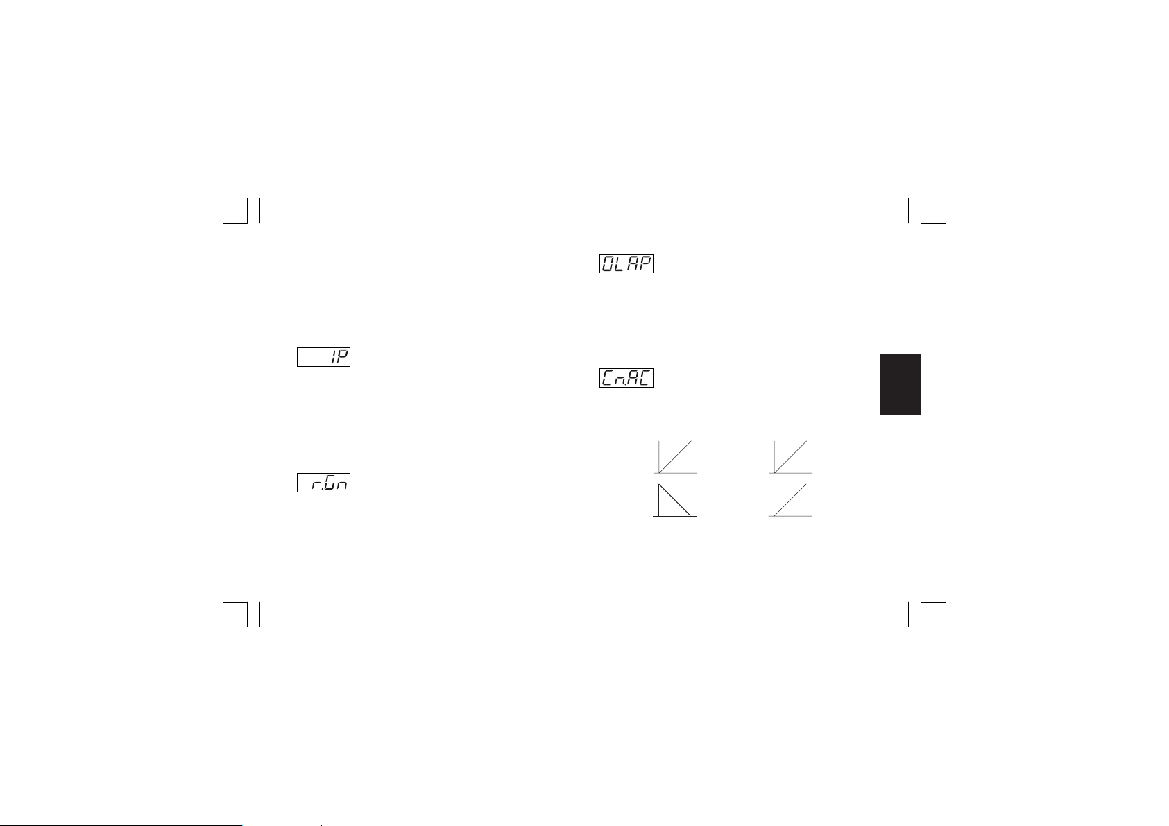
NOTESNOTES
NOTES:
NOTESNOTES
1) When device is working with SMART algorithm and “Cn.tP”
[C.G02] is equal to “Pid”, the “td” value will be made equal
to a quarter of “ti” value.
2) When “Cn.tP” [C.G02] is equal to “Pi”, the derivative action is
excluded
- Integral preload - [r.d05]- Integral preload - [r.d05]
- Integral preload - [r.d05]
- Integral preload - [r.d05]- Integral preload - [r.d05]
This parameter is available when at least one control output is
configured and "Pb" [r.d01] is different from 0.
Ranges:
- from 0.0 to 100.0 % of the output when device is configured
with only one control output
- from -100.0 to 100.0 % of the output when device is
configured with two control outputs (split range excluded)
- Overlap/dead band between main and- Overlap/dead band between main and
- Overlap/dead band between main and
- Overlap/dead band between main and- Overlap/dead band between main and
secondary outputs - [r.d07]secondary outputs - [r.d07]
secondary outputs - [r.d07]
secondary outputs - [r.d07]secondary outputs - [r.d07]
This parameter is available when two control outputs are
configured (split range excluded) and "Pb" [r.d01] is different
from 0.
Range: from -20 to 50
NOTENOTE
NOTE: A negative value means a dead band while a positive
NOTENOTE
value means an overlap.
- Control action - [r.d08]- Control action - [r.d08]
- Control action - [r.d08]
- Control action - [r.d08]- Control action - [r.d08]
Range: rE v = reverse action
dir = direct action
REVERSE ACTION DIRECT ACTION
Input
Input
Gr. 4Gr. 4
Gr. 4Gr. 4
Gr. 4
- Relative secondary output gain - [r.d06]- Relative secondary output gain - [r.d06]
- Relative secondary output gain - [r.d06]
- Relative secondary output gain - [r.d06]- Relative secondary output gain - [r.d06]
This parameter is available when two control outputs are
configured (split range excluded) and "Pb" [r.d01] is different
from 0.
Range: from 0.20 to 2.00
XKP-1-D1.pmd 25/05/2006, 11.2879
t
Output
Output
t
79
t
t
Page 84

NOTESNOTES
NOTES:
NOTESNOTES
1) When device is configured with two control outputs (split
range excluded) the control action is forced to reverse and it
cannot be modified.
2) When direct/reverse selection is performed by a logic input
this parameter allows you to monitor the current selected
action only.
General notes about PID parametersGeneral notes about PID parameters
General notes about PID parameters
General notes about PID parametersGeneral notes about PID parameters
The standard PID parameters (the PID parameters not related
with a PID group) are the real parameters used during run time
mode.
During a program execution, if a specific PID group is assigned
Gr. 4Gr. 4
Gr. 4Gr. 4
Gr. 4
to a segment, the instrument assignes to the standard PID
parameter the values programed for the specific PID group.
For this reason, if a standard PID parameter is modified, no
changement is made on the PID groups while if a changement
is made on the PID group currently used, the standard PID
parameters will be immediately aligned to it.
XKP-1-D1.pmd 25/05/2006, 11.2880
- Proportional band of the first PID group- Proportional band of the first PID group
- Proportional band of the first PID group
- Proportional band of the first PID group- Proportional band of the first PID group
- [r.d09]- [r.d09]
- [r.d09]
- [r.d09]- [r.d09]
This parameter is available when at least one control output is
configured and the instrument is in programmer mode.
Lower display: Pb x where x is the number of the selected PID
group.
Range: from 0.5% to 999.0% of the input span.
Set 0.0% for On/OFF control action
NOTESNOTES
NOTES:
NOTESNOTES
1) The Pb resolution will be equal to 0.1% up to 10.0% and 1%
up to 999.0 %.
2) When device is working with SMART algorithm the “Pb”
value will be limited as selected by parameters “Pb.Hi”
[r.M02] and “Pb.Lo” [r.M01].
80
Page 85
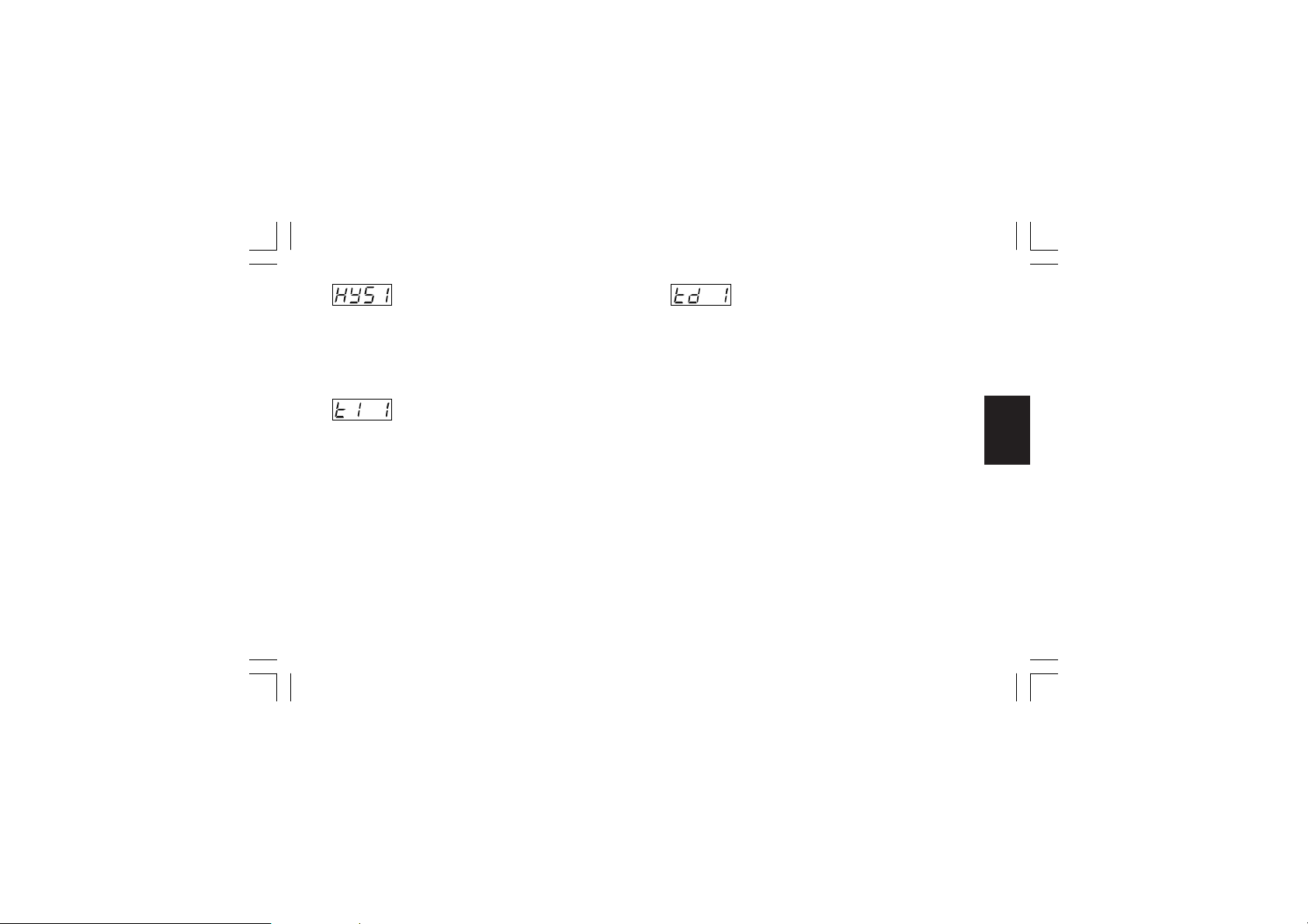
- Hysteresis (for ON/OFF control) of the first- Hysteresis (for ON/OFF control) of the first
- Hysteresis (for ON/OFF control) of the first
- Hysteresis (for ON/OFF control) of the first- Hysteresis (for ON/OFF control) of the first
PID group - [r.d10]PID group - [r.d10]
PID group - [r.d10]
PID group - [r.d10]PID group - [r.d10]
This parameter is available when Pb [r.d01]=0 (On/OFF control
action) and the instrument is in programmer mode.
Lower display: HYS x where x is the number of the selected
PID group.
Range: from 0.1% to 10.0% of the input span.
- Integral time of the first PID group - [r.d11]- Integral time of the first PID group - [r.d11]
- Integral time of the first PID group - [r.d11]
- Integral time of the first PID group - [r.d11]- Integral time of the first PID group - [r.d11]
This parameter is available when at least one control output is
configured, Pb [r.d01] is different from 0 and the instrument is
in programmer mode..
Lower display: ti x where x is the number of the selected PID
group.
Range: from 00.01 to 20.00 mm.ss
Above this value the display blanks and the integral
action is excluded
NOTENOTE
NOTE: When device is working with SMART algorithm the “ti”
NOTENOTE
value will be limited as selected by “ti.Hi” [r.M04] and “ti.Lo”
[r.M03].
XKP-1-D1.pmd 25/05/2006, 11.2881
- Derivative time of the first PID group - [r.d12]- Derivative time of the first PID group - [r.d12]
- Derivative time of the first PID group - [r.d12]
- Derivative time of the first PID group - [r.d12]- Derivative time of the first PID group - [r.d12]
This parameter is available when at least one control output is
configured, “Cn.tP” [C.G02] is equal to “Pid”, "Pb" [r.d01] is
different from 0 and the instrument is in programmer mode.
Lower display: td x where x is the number of the selected PID
group.
Range: From 00.00 to 10.00 mm.ss
NOTESNOTES
NOTES:
NOTESNOTES
1) When device is working with SMART algorithm and “Cn.tP”
[C.G02] is equal to “Pid”, the “td” value will be equal to a
quarter of “ti” value.
2) When “Cn.tP” [C.G02] is equal to “Pi”, the derivative action is
excluded
81
Gr. 4Gr. 4
Gr. 4Gr. 4
Gr. 4
Page 86
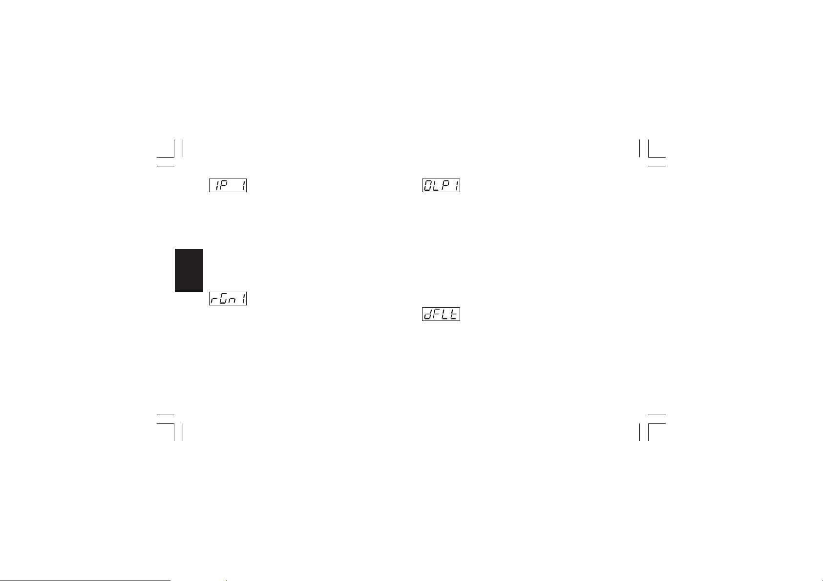
- Integral preload of the first PID group- Integral preload of the first PID group
- Integral preload of the first PID group
- Integral preload of the first PID group- Integral preload of the first PID group
- [r.d13]- [r.d13]
- [r.d13]
- [r.d13]- [r.d13]
This parameter is available when at least one control output is
configured, "Pb" [r.d01] is different from 0 and the instrument is
in programmer mode.
Lower display: IP x where x is the number of the selected PID
group.
Ranges:
- from 0.0 to 100.0 % of the output when device is configured
with only one control output
- from -100.0 to 100.0 % of the output when device is
configured with two control outputs (split range excluded)
Gr. 5Gr. 5
Gr. 5Gr. 5
Gr. 4Gr. 4
Gr. 4Gr. 4
Gr. 5
Gr. 4
- Relative secondary output gain of the first- Relative secondary output gain of the first
- Relative secondary output gain of the first
- Relative secondary output gain of the first- Relative secondary output gain of the first
PID group - [r.d14]PID group - [r.d14]
PID group - [r.d14]
PID group - [r.d14]PID group - [r.d14]
This parameter is available when two control outputs are
configured (split range excluded), "Pb" [r.d01] is different from 0
and the instrument is in programmer mode.
Lower display: r.Gnx where x is the number of the selected PID
group.
Range: from 0.20 to 2.00
XKP-1-D1.pmd 25/05/2006, 11.2882
- Overlap/dead band between main and- Overlap/dead band between main and
- Overlap/dead band between main and
- Overlap/dead band between main and- Overlap/dead band between main and
secondary outputs of the first PID groupsecondary outputs of the first PID group
secondary outputs of the first PID group
secondary outputs of the first PID groupsecondary outputs of the first PID group
- [r.d15]- [r.d15]
- [r.d15]
This parameter is available when two control outputs are
- [r.d15]- [r.d15]
configured (split range excluded), "Pb" [r.d01] is different from 0
and the instrument is in programmer mode.
Lower display: OLPx where x is the number of the
selected PID group.
Range: from -20 to 50
NOTENOTE
NOTE: A negative value means a dead band while a positive
NOTENOTE
value means an overlap.
NOTENOTE
NOTE: For PID group 2 to 5, the instrument will show on the
NOTENOTE
lower display the respective PID group number and it is
possible to perform the same setting described for PID group 1.
- Group 4 default data loading - [r.d16]- Group 4 default data loading - [r.d16]
- Group 4 default data loading - [r.d16]
- Group 4 default data loading - [r.d16]- Group 4 default data loading - [r.d16]
Range: OFF = No loading data
ON = Loading data
82
Page 87

Run time group 5 [r.Exx]Run time group 5 [r.Exx]
Run time group 5 [r.Exx]
Run time group 5 [r.Exx]Run time group 5 [r.Exx]
AUXILIARY CONTROL PARAMETER
- Anti reset wind up - [r.E01]- Anti reset wind up - [r.E01]
- Anti reset wind up - [r.E01]
- Anti reset wind up - [r.E01]- Anti reset wind up - [r.E01]
This parameter is available when at least one control output is
configured and "Pb" [r.d01] is different from 0.
Range: from 10% to 200% of the input span
- Servo motor travel time - [r.E02]- Servo motor travel time - [r.E02]
- Servo motor travel time - [r.E02]
- Servo motor travel time - [r.E02]- Servo motor travel time - [r.E02]
This parameter is available when the open loop servomotor
control drive output is configured (“O3.Fn” [C.E03] is equal to
“ñC.Sñ” or “SC.Sñ” and “Sñ.tP” [C.E05] is equal to “OPEn”).
Range: from 0.12 to 3.00 m.ss
XKP-1-D1.pmd 25/05/2006, 11.2883
- Servo motor dead band - [r.E03]- Servo motor dead band - [r.E03]
- Servo motor dead band - [r.E03]
- Servo motor dead band - [r.E03]- Servo motor dead band - [r.E03]
This parameter is available when the servomotor control drive
output is configured (“O3.Fn” [C.E03] is equal to “ñC.Sñ” or
“SC.Sñ” ).
Range: from 1% to 50%
- Main control output low limit - [r.E04]- Main control output low limit - [r.E04]
- Main control output low limit - [r.E04]
- Main control output low limit - [r.E04]- Main control output low limit - [r.E04]
This parameter is available when one control output is
configured as main output.
Range: from 0.0 % (of the output span) to ñ.OLH [r.E05]
- Main control output high limit - [r.E05]- Main control output high limit - [r.E05]
- Main control output high limit - [r.E05]
- Main control output high limit - [r.E05]- Main control output high limit - [r.E05]
This parameter is available when one control output is
configured as main output.
Range: from ñ.OLL [r.E04] to 100.0 % of the output span.
83
Gr. 5Gr. 5
Gr. 5Gr. 5
Gr. 5
Page 88
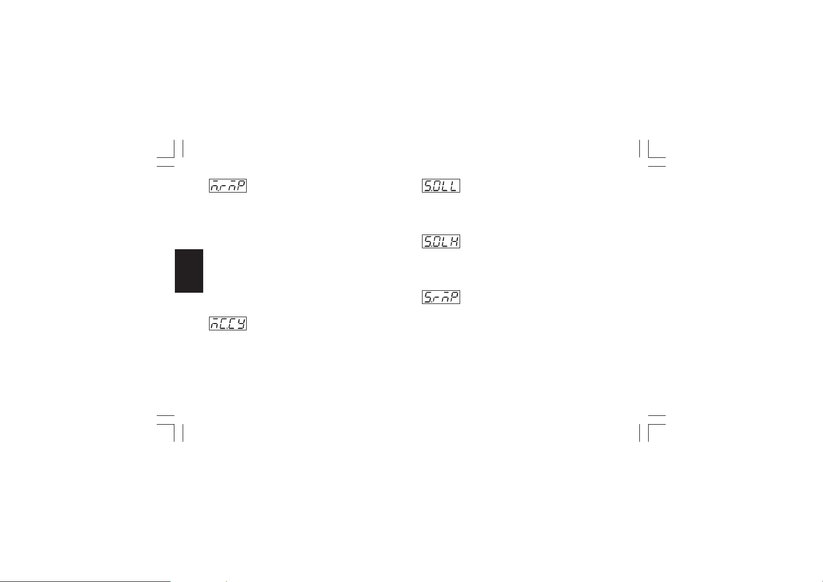
- Main control output max rate of rise - [r.E06]- Main control output max rate of rise - [r.E06]
- Main control output max rate of rise - [r.E06]
- Main control output max rate of rise - [r.E06]- Main control output max rate of rise - [r.E06]
This parameter is available when one control output is
configured as main output.
Ranges: from 0.1%/s to 25.0%/s.
Above this value the display shows “Inf” meaning that no limit is
imposed
NOTESNOTES
NOTES:
NOTESNOTES
1) This parameter will be active even if device is configured for
On/OFF control.
2) During the transfert from AUTO to MANUAL, if this action is
programmed as a not bumpless transfer, the “ñ.rñP” function
will be ignored and the output will step up to the value set by
Gr. 5Gr. 5
Gr. 5Gr. 5
Gr. 5
“Añ.UL” [C.G04] parameter.
- Main output cycle time - [r.E07]- Main output cycle time - [r.E07]
- Main output cycle time - [r.E07]
- Main output cycle time - [r.E07]- Main output cycle time - [r.E07]
This parameter is available when a time proportional main
control output is configured.
Range: from 1 to 200 s
XKP-1-D1.pmd 25/05/2006, 11.2884
- Secondary control output low limit - [r.E08]- Secondary control output low limit - [r.E08]
- Secondary control output low limit - [r.E08]
- Secondary control output low limit - [r.E08]- Secondary control output low limit - [r.E08]
This parameter is available when one control output is
configured as secondary control output.
Range: From 0.0 % of the output span to S.OLH [r.E09].
- Secondary control output high limit - [r.E09]- Secondary control output high limit - [r.E09]
- Secondary control output high limit - [r.E09]
- Secondary control output high limit - [r.E09]- Secondary control output high limit - [r.E09]
This parameter is available when one control output is
configured as secondary control output.
Range: from S.OLL [r.E08] to 100.0 % of the output span
- Secondary control output max rate of rise- Secondary control output max rate of rise
- Secondary control output max rate of rise
- Secondary control output max rate of rise- Secondary control output max rate of rise
- [r.E10]- [r.E10]
- [r.E10]
- [r.E10]- [r.E10]
This parameter is available when one control output is
configured as secondary control output.
Ranges: from 0.1%/s to 25.0%/s.
Above this value the display shows “Inf” meaning that no limit is
imposed
NOTESNOTES
NOTES:
NOTESNOTES
1) This parameter will be active even if device is configured for
ON/OFF control.
2) During the transfer from AUTO to MANUAL, if this action is
programmed as a not bumpless transfer, the “S.rñP” function
84
Page 89
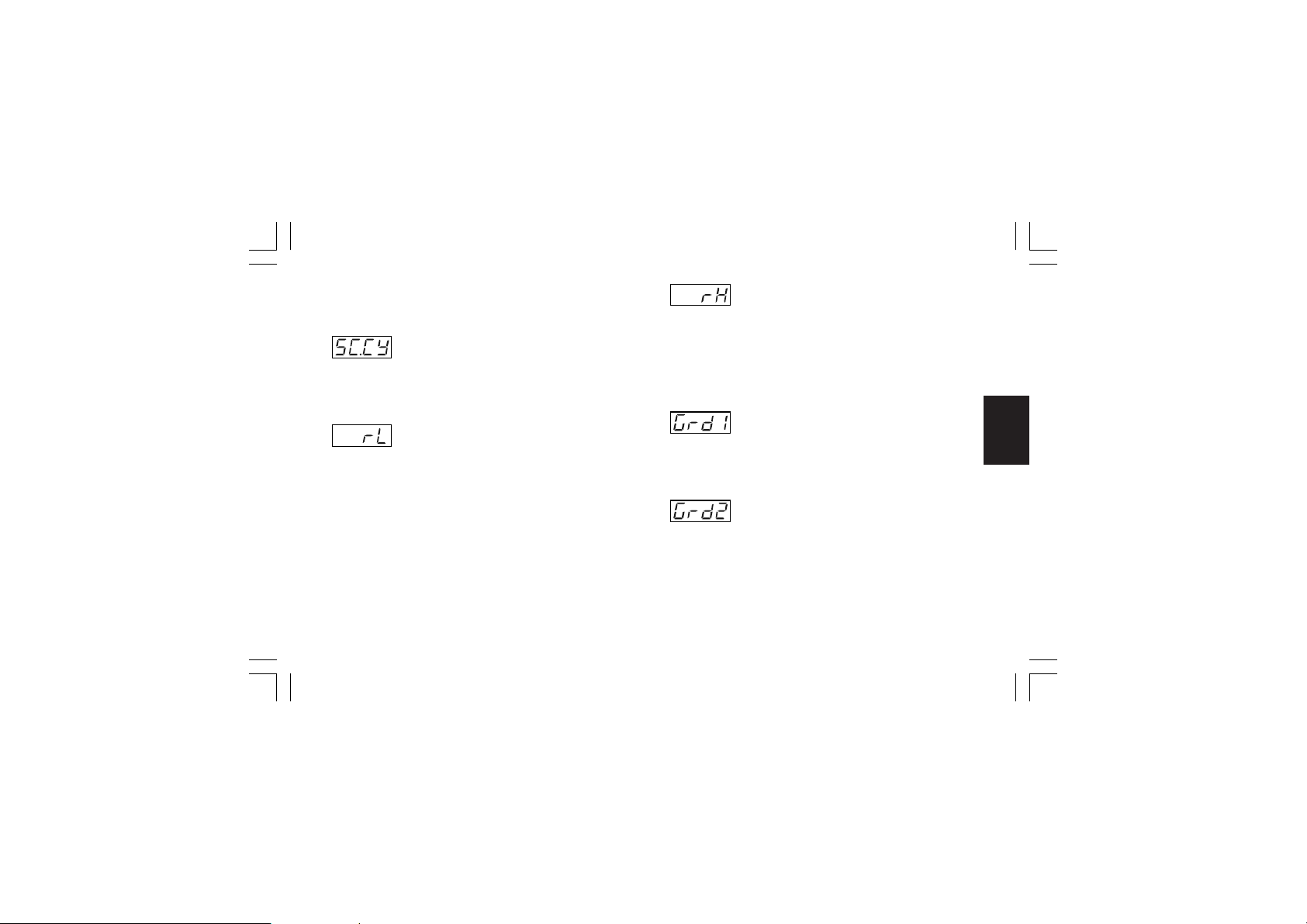
will be ignored and the output will step up to the value set by
“Añ.UL” [C.G04] parameter.
- Secondary output cycle time - [r.E11]- Secondary output cycle time - [r.E11]
- Secondary output cycle time - [r.E11]
- Secondary output cycle time - [r.E11]- Secondary output cycle time - [r.E11]
This parameter is available when a time proportional secondary
control output is configured.
Range: from 1 to 200 s
- Set point low limit - [r.E12] - Set point low limit - [r.E12]
- Set point low limit - [r.E12]
- Set point low limit - [r.E12] - Set point low limit - [r.E12]
Range: From “ñ.In.L” [C.d05] to rH [r.E13].
NOTESNOTES
NOTES: Whenever “ñ.In.L” [C.d05] has been modified, the
NOTESNOTES
following occurs:
1) rL will be realigned to it;
2) if the set point values are out of the new limits, "rL"
automatically assumes the default value.
XKP-1-D1.pmd 25/05/2006, 11.2885
- Set point high limit - [r.E13]- Set point high limit - [r.E13]
- Set point high limit - [r.E13]
- Set point high limit - [r.E13]- Set point high limit - [r.E13]
Range: from rL [r.E12] to “ñ.In.H” [C.d06].
NOTESNOTES
NOTES: Whenever “ñ.In.H” [C.d06] has been modified, the
NOTESNOTES
following occurs:
1) rH will be realigned to it;
2) if the set point values are out of the new limits, "rH"
automatically assumes the default value.
- Rate of change for positive set point- Rate of change for positive set point
- Rate of change for positive set point
- Rate of change for positive set point- Rate of change for positive set point
variations - [r.E14]variations - [r.E14]
variations - [r.E14]
variations - [r.E14]variations - [r.E14]
Range: from 1 to 200 digits per minute.
Above this value the display shows “Inf” and the transfer will be
a step change.
- Rate of change for negative set point- Rate of change for negative set point
- Rate of change for negative set point
- Rate of change for negative set point- Rate of change for negative set point
variations - [r.E15]variations - [r.E15]
variations - [r.E15]
variations - [r.E15]variations - [r.E15]
Range: from 1 to 200 digits per minutes.
Above this value the display shows “Inf” and the transfer will be
a step change.
85
Gr. 5Gr. 5
Gr. 5Gr. 5
Gr. 5
Page 90
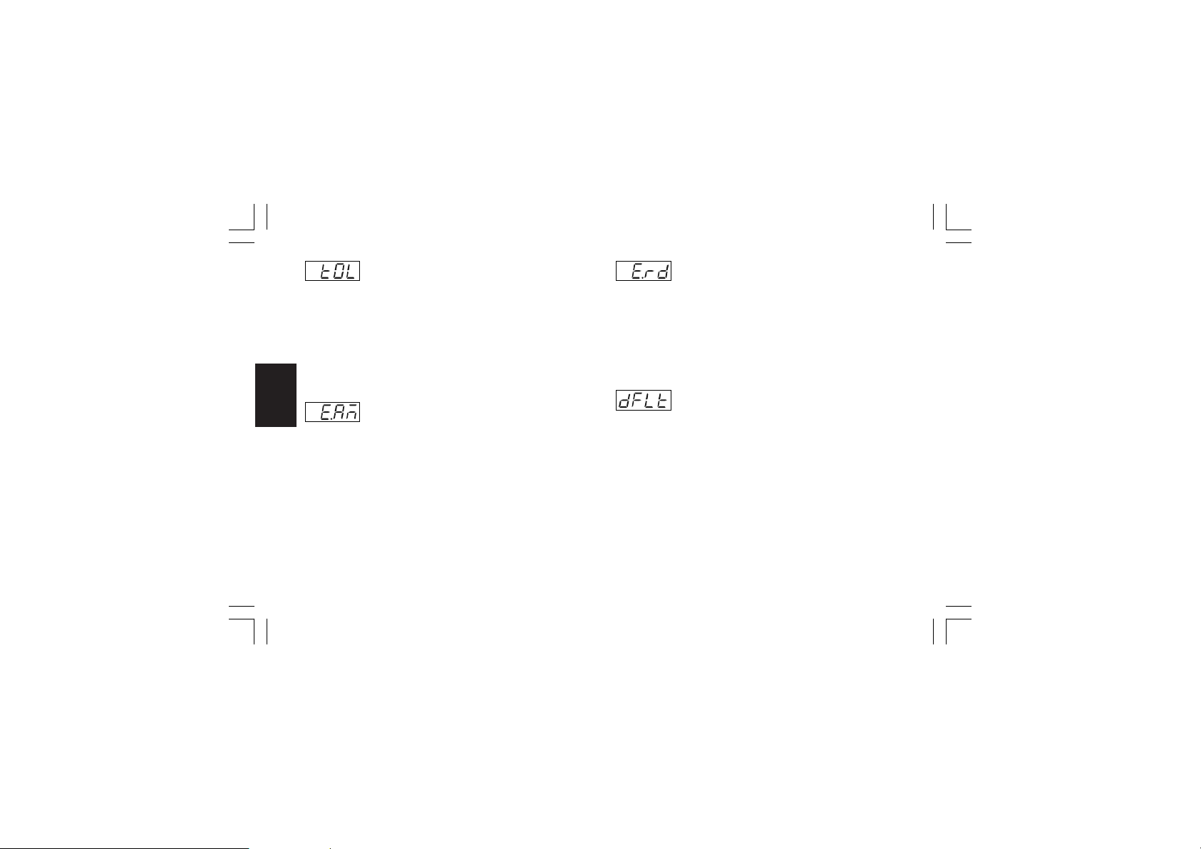
- Time out for the soft start - [r.E16]- Time out for the soft start - [r.E16]
- Time out for the soft start - [r.E16]
- Time out for the soft start - [r.E16]- Time out for the soft start - [r.E16]
This parameter is available when at least one output is
configured as control output and no logic input is configured as
“Output limiter activator”.
Range: from 1 to 540 min.
Above this value the display shows “InF” and the limiting action
is always active.
NOTENOTE
NOTE: The tOL can be always modified but the new value will be
NOTENOTE
used only at the next device power up
- External control for AUTO /MANUAL mode- External control for AUTO /MANUAL mode
- External control for AUTO /MANUAL mode
- External control for AUTO /MANUAL mode- External control for AUTO /MANUAL mode
- [r.E17]- [r.E17]
Gr. 6Gr. 6
Gr. 6Gr. 6
Gr. 5Gr. 5
Gr. 5Gr. 5
Gr. 6
Gr. 5
- [r.E17]
- [r.E17]- [r.E17]
This parameter is available when one of the logic inputs is
configured for Auto/Manual selection and no program is
running.
Range:On the Auto/Manual selection is made by logic input
only
OF F the Auto/Manual selection is made by “Man” key
or serial link only.
XKP-1-D1.pmd 25/05/2006, 11.2886
- External control for reverse/direct output- External control for reverse/direct output
- External control for reverse/direct output
- External control for reverse/direct output- External control for reverse/direct output
action selection - [r.E18]action selection - [r.E18]
action selection - [r.E18]
action selection - [r.E18]action selection - [r.E18]
This parameter is available when one of the logic inputs is
configured for direct/reverse output action selection.
Range:On the reverse/direct selection is made by external
contact only
OF F the reverse/direct selection is made by “Cn.Ac”
[r.d08] parameter or serial link only.
- Group 5 default data loading - [r.E19]- Group 5 default data loading - [r.E19]
- Group 5 default data loading - [r.E19]
- Group 5 default data loading - [r.E19]- Group 5 default data loading - [r.E19]
Range: OFF = No loading data
ON = Loading data
86
Page 91
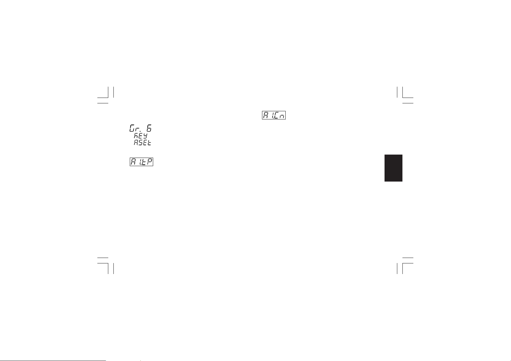
Run time group 6 [r.Fxx]Run time group 6 [r.Fxx]
Run time group 6 [r.Fxx]
Run time group 6 [r.Fxx]Run time group 6 [r.Fxx]
ALARM SETTING
- Alarm 1 type - [r.F01]- Alarm 1 type - [r.F01]
- Alarm 1 type - [r.F01]
- Alarm 1 type - [r.F01]- Alarm 1 type - [r.F01]
This parameter is available only when OUT 1 is configured as
alarm 1 output (“O1.Fn” [C.E01] = “ALr.1”)
Range:Proc = Alarm on process variable
bAnd = Band alarm on process variable
dE V = Deviation alarm on process variable
ñAi n = Alarm on Main control output value
SECn= Alarm on Secondary control output value
NOTENOTE
NOTE: When alarm type has been changed the alarm
NOTENOTE
threshold will be forced to its default value and alarm status will
be deleted.
XKP-1-D1.pmd 25/05/2006, 11.2887
- Alarm 1 configuration - [r.F02]- Alarm 1 configuration - [r.F02]
- Alarm 1 configuration - [r.F02]
- Alarm 1 configuration - [r.F02]- Alarm 1 configuration - [r.F02]
This parameter is available only when OUT 1 is configured as
alarm 1 output (“O1.Fn” [C.E01] = “ALr.1”)
Range: H.A. = High alarm (outside band) with automatic
reset
L.A. = Low alarm (inside band) with automatic reset
H.A.Ac= High alarm (outside band) with automatic
reset and acknowledge
L.A.Ac= Low alarm (inside band) with automatic reset
and acknowledge
H.L. = High alarm (outside band) with manual reset
L.L. = Low alarm (inside band) with manual reset
NOTENOTE
NOTE: When alarm configuration has been changed, the alarm
NOTENOTE
status will be deleted.
87
Gr. 6Gr. 6
Gr. 6Gr. 6
Gr. 6
Page 92
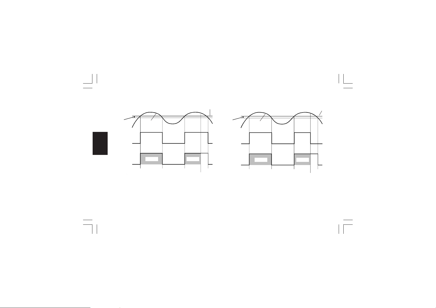
ExampleExample
Example for A1.Cn (A2.Cn, A3.Cn) = H.A.
ExampleExample
Alarm
Hysteresis
Measured
Value
ON
Relay out
OFF
Gr. 6Gr. 6
Gr. 6Gr. 6
Gr. 6
ON
LED 1(2, 3)
Flash
Flash
OFF
A
B
A
A= alarm condition detection
B= automatic reset of alarm
C= manual reset; the LED gets steady lit, the alarm remains in
the alarm status until the process variable reaches the
alarm threshold minus hysteresis (D).
XKP-1-D1.pmd 25/05/2006, 11.2888
Alarm
Threshold
Steady
D
C
ExampleExample
Example for A1.Cn (A2.Cn, A3.Cn) = H.A.A.c
ExampleExample
Alarm
Hysteresis
Measured
Value
ON
Relay out
OFF
ON
LED 1(2, 3)
Flash
Flash
OFF
A
B
A
A= alarm condition detection
B= automatic reset of alarm
C= manual reset; the LED gets steady lit, the relay output goes
OFF but the LED remains steady lit until the process
variable reaches the alarm threshold minus hysteresis (D).
88
Alarm
Threshold
Steady
C
D
Page 93
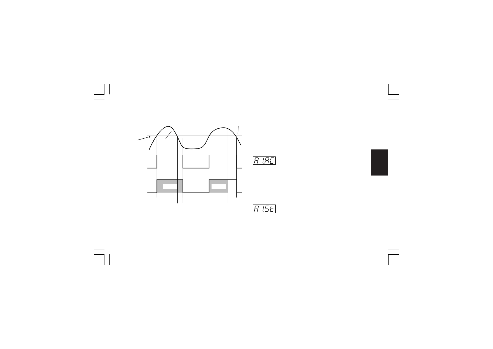
ExampleExample
Example for A1.Cn (A2.Cn, A3.Cn) = H.L.
ExampleExample
Alarm
Hysteresis
Measured
Value
OFF
Relay out
ON
ON
LED 1(2, 3)
FlashFlash
OFF
A
B
C
A
A= alarm condition detection
B= the alarm remains in alarm status (even if the measured
value is under the threshold) until a manual reset is
performed (C).
XKP-1-D1.pmd 25/05/2006, 11.2889
Alarm
Threshold
Steady
D
E
E= if a manual reset is performed when the alarm condition still
exist; the LED gets steady lit, the alarm remains in the
alarm status until the process variable reaches the alarm
threshold minus hysteresis (D).
NOTENOTE
NOTE:
NOTENOTE
The manual reset (acknowledgement) may be performed by the
"ñ.rSt" [R.C01] parameter or by logic input or by serial link.
- Alarm 1 action - [r.F03]- Alarm 1 action - [r.F03]
- Alarm 1 action - [r.F03]
- Alarm 1 action - [r.F03]- Alarm 1 action - [r.F03]
This parameter is available only when OUT 1 is configured as
alarm 1 output (“O1.Fn” [C.E01] = “ALr.1”)
Range: dir = direct action (Relay energized or SSr=1 in
alarm condition)
rE V = Reverse action (Relay energized or SSr=1 in
non alarm condition)
- Alarm 1 stand by (mask) function - [r.F04]- Alarm 1 stand by (mask) function - [r.F04]
- Alarm 1 stand by (mask) function - [r.F04]
- Alarm 1 stand by (mask) function - [r.F04]- Alarm 1 stand by (mask) function - [r.F04]
This parameter is available only when OUT 1 is configured as
alarm 1 output (“O1.Fn” [C.E01] = “ALr.1”)
Range: OFF = Stand-by function disabled
On = Stand-by function enabled
89
Gr. 6Gr. 6
Gr. 6Gr. 6
Gr. 6
Page 94
NOTESNOTES
NOTES:
NOTESNOTES
1) If the alarm is programmed as band or deviation alarm, this
function masks the alarm condition after a set point change
or at the instrument start-up until process variable reaches
the alarm threshold plus or minus hysteresis. If the alarm is
programmed as a process alarm or control output alarm, this
function masks the alarm condition at instrument start-up
until process variable reaches the alarm threshold plus or
minus hysteresis.
2) The change from On to OFF has immediate effect, while the
change from OFF to On has effect at the next start up or set
point change.
Gr. 6Gr. 6
Gr. 6Gr. 6
Gr. 6
- Alarm 2 type - [r.F05]- Alarm 2 type - [r.F05]
- Alarm 2 type - [r.F05]
- Alarm 2 type - [r.F05]- Alarm 2 type - [r.F05]
This parameter is available only when OUT 2 is configured as
alarm 2 output (“O2.Fn” [C.E02] = “ALr.2”)
Range:Proc = Alarm on process variable
bAnd = Band alarm on process variable
dE V = Deviation alarm on process variable
ñAi n = Alarm on Main control output value
SECn= Alarm on Secondary control output value
XKP-1-D1.pmd 25/05/2006, 11.2890
NOTENOTE
NOTE: When alarm type has been changed the alarm
NOTENOTE
threshold will be forced to its default value and alarm status will
be deleted.
- Alarm 2 configuration - [r.F06]- Alarm 2 configuration - [r.F06]
- Alarm 2 configuration - [r.F06]
- Alarm 2 configuration - [r.F06]- Alarm 2 configuration - [r.F06]
This parameter is available only when OUT 2 is configured as
alarm 2 output (“O2.Fn” [C.E02] = “ALr.2”)
Range: H.A. = High alarm (outside band) with automatic
reset
L.A. = Low alarm (inside band) with automatic reset
H.A.Ac= High alarm (outside band) with automatic
reset and acknowledge
L.A.Ac= Low alarm (inside band) with automatic reset
and acknowledge
H.L. = High alarm (outside band) with manual reset
L.L. = Low alarm (inside band) with manual reset
NOTENOTE
NOTE: When alarm configuration has been changed, the alarm
NOTENOTE
status will be deleted.
90
Page 95
- Alarm 2 action - [r.F07]- Alarm 2 action - [r.F07]
- Alarm 2 action - [r.F07]
- Alarm 2 action - [r.F07]- Alarm 2 action - [r.F07]
This parameter is available only when OUT 2 is configured as
alarm 2 output (“O2.Fn” [C.E02] = “ALr.2”)
Range: dir = direct action (Relay energized or SSr=1 in
alarm condition)
rE V = Reverse action (Relay energized or SSr=1 in
non alarm condition)
- Alarm 2 stand by (mask) function - [r.F08]- Alarm 2 stand by (mask) function - [r.F08]
- Alarm 2 stand by (mask) function - [r.F08]
- Alarm 2 stand by (mask) function - [r.F08]- Alarm 2 stand by (mask) function - [r.F08]
This parameter is available only when OUT 2 is configured as
alarm 2 output (“O2.Fn” [C.E02] = “ALr.2”)
Range: OFF = Stand-by function disabled
On = Stand-by function enabled
NOTESNOTES
NOTES:
NOTESNOTES
1) If the alarm is programmed as band or deviation alarm, this
function masks the alarm condition after a set point change
or at the instrument start-up until process variable reaches
the alarm threshold plus or minus hysteresis. If the alarm is
programmed as a process alarm or control output alarm, this
function masks the alarm condition at instrument start-up
until process variable reaches the alarm threshold plus or
minus hysteresis.
XKP-1-D1.pmd 25/05/2006, 11.2891
2) The change from On to OFF has immediate effect, while the
change from OFF to On has effect at the next start up or set
point change
- Alarm 3 type - [r.F09]- Alarm 3 type - [r.F09]
- Alarm 3 type - [r.F09]
- Alarm 3 type - [r.F09]- Alarm 3 type - [r.F09]
This parameter is available only when OUT 3 is configured as
alarm 3 output (“O3.Fn” [C.E03] = “ALr.3”)
Range:Proc = Alarm on process variable
bAnd = Band alarm on process variable
dE V = Deviation alarm on process variable
ñAi n = Alarm on Main control output value
SECn= Alarm on Secondary control output value
NOTENOTE
NOTE: When alarm type has been changed the alarm
NOTENOTE
threshold will be forced to its default value and alarm status will
be cleared.
91
Gr. 6Gr. 6
Gr. 6Gr. 6
Gr. 6
Page 96
- Alarm 3 configuration - [r.F10]- Alarm 3 configuration - [r.F10]
- Alarm 3 configuration - [r.F10]
- Alarm 3 configuration - [r.F10]- Alarm 3 configuration - [r.F10]
This parameter is available only when OUT 3 is configured as
alarm 3 output (“O3.Fn” [C.E03] = “ALr.3”)
Range: H.A. = High alarm (outside band) with automatic
reset
L.A. = Low alarm (inside band) with automatic reset
H.A.Ac= High alarm (outside band) with automatic
reset and acknowledge
L.A.Ac= Low alarm (inside band) with automatic reset
and acknowledge
H.L. = High alarm (outside band) with manual reset
Gr. 6Gr. 6
Gr. 6Gr. 6
Gr. 6
L.L. = Low alarm (inside band) with manual reset
NOTENOTE
NOTE: When alarm configuration has been changed, the alarm
NOTENOTE
status will be deleted.
- Alarm 3 action - [r.F11]- Alarm 3 action - [r.F11]
- Alarm 3 action - [r.F11]
- Alarm 3 action - [r.F11]- Alarm 3 action - [r.F11]
This parameter is available only when OUT 3 is configured as
alarm 3 output (“O3.Fn” [C.E03] = “ALr.3”)
Range: dir = direct action (Relay energized or SSr=1 in
alarm condition)
rE V = Reverse action (Relay energized or SSr=1 in
non alarm condition)
XKP-1-D1.pmd 25/05/2006, 11.2892
- Alarm 3 standby (mask) function - [r.F12]- Alarm 3 standby (mask) function - [r.F12]
- Alarm 3 standby (mask) function - [r.F12]
- Alarm 3 standby (mask) function - [r.F12]- Alarm 3 standby (mask) function - [r.F12]
This parameter is available only when OUT 3 is configured as
alarm 3 output (“O3.Fn” [C.E03] = “ALr.3”)
Range:O FF = Stand-by function disabled
On = Stand-by function enabled
NOTESNOTES
NOTES:
NOTESNOTES
1) If the alarm is programmed as band or deviation alarm, this
function masks the alarm condition after a set point change
or at the instrument start-up until process variable reaches
the alarm threshold plus or minus hysteresis. If the alarm is
programmed as a process alarm or control output alarm, this
function masks the alarm condition at instrument start-up
until process variable reaches the alarm threshold plus or
minus hysteresis.
2) The change from On to OFF has immediate effect, while the
change from OFF to On has effect at the next start up or set
point change
92
Page 97
- Alarm 4 type - [r.F13]- Alarm 4 type - [r.F13]
- Alarm 4 type - [r.F13]
- Alarm 4 type - [r.F13]- Alarm 4 type - [r.F13]
This parameter is available only when OUT 4 is configured as
alarm 4 output (“O4.Fn” [C.E04] = “ALr.4”)
Range:Proc = Alarm on process variable
bAnd = Band alarm on process variable
dE V = Deviation alarm on process variable
ñAi n = Alarm on Main control output value
SECn= Alarm on Secondary control output value
NOTENOTE
NOTE: When alarm type has been changed the alarm
NOTENOTE
threshold will be forced to its default value and alarm status will
be deleted.
- Alarm 4 configuration - [r.F14]- Alarm 4 configuration - [r.F14]
- Alarm 4 configuration - [r.F14]
- Alarm 4 configuration - [r.F14]- Alarm 4 configuration - [r.F14]
This parameter is available only when OUT 4 is configured as
alarm 4 output (“O4.Fn” [C.E04] = “ALr.4”)
Range: H.A. = High alarm (outside band) with automatic
reset
L.A. = Low alarm (inside band) with automatic reset
H.A.Ac= High alarm (outside band) with automatic
reset and acknowledge
L.A.Ac= Low alarm (inside band) with automatic reset
and acknowledge
XKP-1-D1.pmd 25/05/2006, 11.2893
H.L. = High alarm (outside band) with manual reset
L.L. = Low alarm (inside band) with manual reset
NOTENOTE
NOTE: When alarm configuration has been changed, the alarm
NOTENOTE
status will be deleted.
- Alarm 4 action - [r.F15]- Alarm 4 action - [r.F15]
- Alarm 4 action - [r.F15]
- Alarm 4 action - [r.F15]- Alarm 4 action - [r.F15]
This parameter is available only when OUT 4 is configured as
alarm 4 output (“O4.Fn” [C.E04] = “ALr.4”)
Range: dir = direct action (Relay energized or SSr=1 in
alarm condition)
rE V = Reverse action (Relay energized or SSr=1 in
non alarm condition)
- Alarm 4 stand-by (mask) function - [r.F16]- Alarm 4 stand-by (mask) function - [r.F16]
- Alarm 4 stand-by (mask) function - [r.F16]
- Alarm 4 stand-by (mask) function - [r.F16]- Alarm 4 stand-by (mask) function - [r.F16]
This parameter is available only when OUT 4 is configured as
alarm 4 output (“O4.Fn” [C.E04] = “ALr.4”)
Range:O F F = Stand-by function disabled
On = Stand-by function enabled
NOTESNOTES
NOTES:
NOTESNOTES
1) If the alarm is programmed as band or deviation alarm, this
function masks the alarm condition after a set point change
or at the instrument start-up until process variable reaches
93
Gr. 6Gr. 6
Gr. 6Gr. 6
Gr. 6
Page 98
the alarm threshold plus or minus hysteresis. If the alarm is
programmed as a process alarm or control output alarm, this
function masks the alarm condition at instrument start-up
until process variable reaches the alarm threshold plus or
minus hysteresis.
2) The change from On to OFF has immediate effect, while the
change from OFF to On has effect at the next start up or set
point change
- OFD (Output Failure Detection) alarm - OFD (Output Failure Detection) alarm
- OFD (Output Failure Detection) alarm
- OFD (Output Failure Detection) alarm - OFD (Output Failure Detection) alarm
configuration - [r.F17]configuration - [r.F17]
configuration - [r.F17]
Gr. 7Gr. 7
Gr. 7Gr. 7
Gr. 6Gr. 6
Gr. 6Gr. 6
Gr. 7
Gr. 6
This parameter is available only when OFD option is configured
configuration - [r.F17]configuration - [r.F17]
(“Fd.Fn” [C.I11] is different from "nOnE").
Range:A. = Alarm with automatic reset
A.Ac = Alarm with automatic reset and acknowledge
L. = Alarm with manual reset
NOTENOTE
NOTE: When alarm configuration has been changed, the alarm
NOTENOTE
status will be deleted.
XKP-1-D1.pmd 25/05/2006, 11.2894
- OFD (Output Failure Detection) alarm action- OFD (Output Failure Detection) alarm action
- OFD (Output Failure Detection) alarm action
- OFD (Output Failure Detection) alarm action- OFD (Output Failure Detection) alarm action
- [r.F18]- [r.F18]
- [r.F18]
- [r.F18]- [r.F18]
This parameter is available only when one output is configured
as OFD alarm annunciator (“Fd.Fn” [C.I11] and “Fd.Ou” [C.I13]
are different from “nonE”).
Range: dir = direct action (Relay energized or SSr=1 in
alarm condition)
rE V = Reverse action (Relay energized or SSr=1 in
non alarm condition)
NOTENOTE
NOTE: When OFD output is in OR condition with an alarm or
NOTENOTE
an event output, the “Fd.Ac” parameter can only be monitored
but not modified and it assumes the same action defined (by
“Alarm Action” or “Event Logic Level”) for the alarm or the
event.
- Group 6 default data loading - [r.F19] - Group 6 default data loading - [r.F19]
- Group 6 default data loading - [r.F19]
- Group 6 default data loading - [r.F19] - Group 6 default data loading - [r.F19]
Range: OFF = No loading data
ON = Loading data
94
Page 99
Run time group 7 [r.Gxx]Run time group 7 [r.Gxx]
Run time group 7 [r.Gxx]
Run time group 7 [r.Gxx]Run time group 7 [r.Gxx]
SERIAL LINK PARAMETER
- Serial interface protocol - [r.G01]- Serial interface protocol - [r.G01]
- Serial interface protocol - [r.G01]
- Serial interface protocol - [r.G01]- Serial interface protocol - [r.G01]
Range:OFF = No serial interface
ñbUS = Modbus
jbUS = Jbus
NOTENOTE
NOTE: When serial interface circuit is not mounted, the middle
NOTENOTE
display will show “no.Pr”
- Serial link device address - [r.G02]- Serial link device address - [r.G02]
- Serial link device address - [r.G02]
- Serial link device address - [r.G02]- Serial link device address - [r.G02]
This parameter is available only when “S.L.Pr” [r.G01] is
different from "OFF".
Range: from 1 to 255
XKP-1-D1.pmd 25/05/2006, 11.2895
- Serial link baud rate - [r.G03]- Serial link baud rate - [r.G03]
- Serial link baud rate - [r.G03]
- Serial link baud rate - [r.G03]- Serial link baud rate - [r.G03]
This parameter is available only when “S.L.Pr” [r.G01] is
different from "OFF".
Range: from 600 to 19200 baud (19200 baud is shown, on
display, as 19.20)
- Serial link byte format - [r.G04]- Serial link byte format - [r.G04]
- Serial link byte format - [r.G04]
- Serial link byte format - [r.G04]- Serial link byte format - [r.G04]
This parameter is available only when “S.L.Pr” [r.G01] is
different from "OFF".
Range:8 = 8 bits without parity
8E = 8 bits + even parity
8O = 8 bits + odd parity
- Group 7 default data loading - [r.G05]- Group 7 default data loading - [r.G05]
- Group 7 default data loading - [r.G05]
- Group 7 default data loading - [r.G05]- Group 7 default data loading - [r.G05]
Range: OFF = No loading data
ON = Loading data
95
Gr. 7Gr. 7
Gr. 7Gr. 7
Gr. 7
Page 100
Run time group 8 [r.Hxx]Run time group 8 [r.Hxx]
Run time group 8 [r.Hxx]
Run time group 8 [r.Hxx]Run time group 8 [r.Hxx]
FEEDBACK POTENTIOMETER ADJUSTMENT
NOTENOTE
NOTE: The run time group 8 will be displayed only if the
NOTENOTE
instrument is in MANUAL mode.
- Feedback potentiometer adjustment- Feedback potentiometer adjustment
- Feedback potentiometer adjustment
- Feedback potentiometer adjustment- Feedback potentiometer adjustment
enabling - [r.H01]enabling - [r.H01]
enabling - [r.H01]
Gr. 8Gr. 8
Gr. 8Gr. 8
Gr. 8
This parameter is available only when close loop servomotor
enabling - [r.H01]enabling - [r.H01]
output or open loop servomotor output with valve position
indication is configured.
Range:O FF = this selection disables the feedback
potentiometer calibration and the instrument
will come back to the first display of the run
time group 8.
On = this selection starts the feedback potentiometer
adjustment.
NOTENOTE
NOTE: No time out will be applied during
NOTENOTE
feedback potentiometer calibration procedure.
XKP-1-D1.pmd 25/05/2006, 11.2896
- Servomotor low limit positioning - [r.H02]- Servomotor low limit positioning - [r.H02]
- Servomotor low limit positioning - [r.H02]
- Servomotor low limit positioning - [r.H02]- Servomotor low limit positioning - [r.H02]
This parameter is available only when feedback potentiometer
calibration enabling [r.H01] is equal to On.
Range: 0.0% to 100.0%
The middle display will show the valve position as a percentage
of the full input span.
By and push-button it is possible to modify the valve
position.
When the desired initial position has been reached, push the
FUNC push-button.
- Feedback low limit calibration - [r.H03]- Feedback low limit calibration - [r.H03]
- Feedback low limit calibration - [r.H03]
- Feedback low limit calibration - [r.H03]- Feedback low limit calibration - [r.H03]
This parameter is available only when feedback potentiometer
calibration enabling [r.H01] is equal to On.
Range:O FF = To skip adjustment and hold the previous value
select OFF and then push FUNC
On = To memorize the current position as feedback
low limit calibration select “On” and then push
FUNC
96
 Loading...