

Page 1
170.MAN.MEM.2D1 01/0
r USER MANUAL
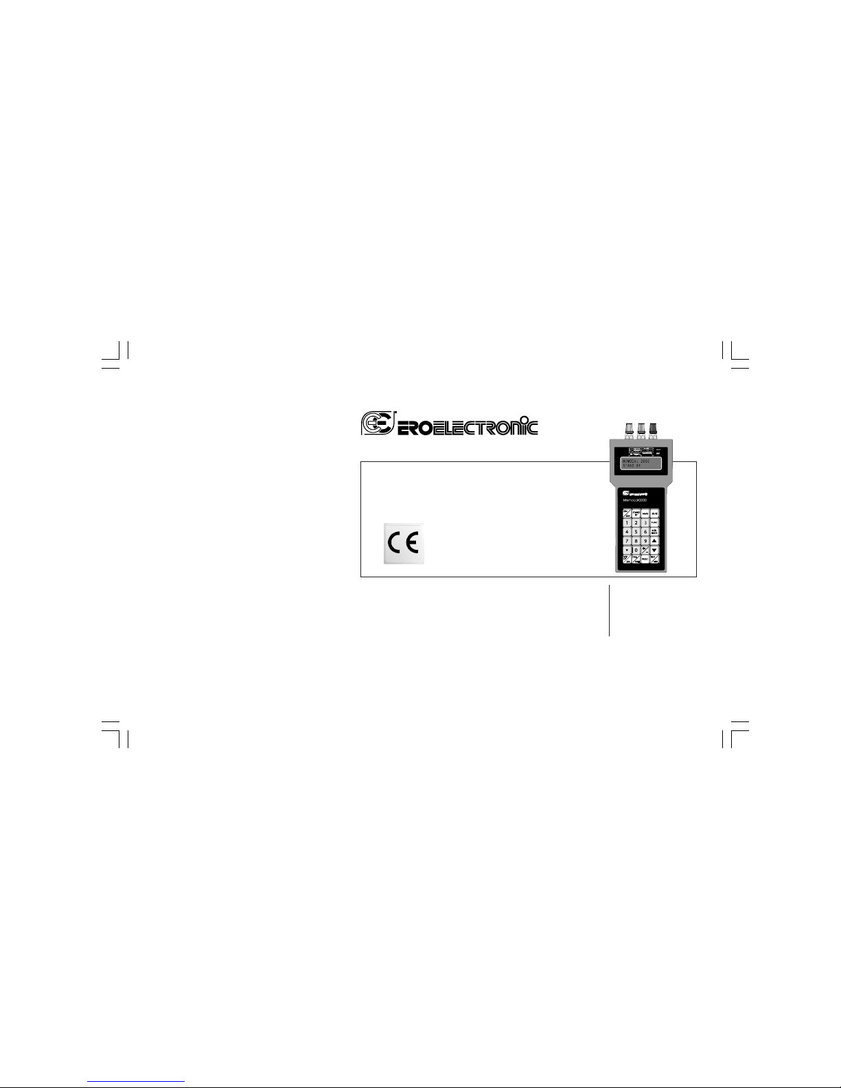
MEMOCAL
2000
M20-e-0.p65 7/9/01, 2:39 PM1
Page 2

CONTENTS
SECTION 1 GENERAL INFORMATION
1.1 INTRODUCTION ........................................................... Page 4
1.2 PRODUCT SPECIFICATIONS ................................................ 4
1.3 SERIAL INTERFACE ............................................................. 11
1.4 SEQUENTIAL FUNCTION ROUTINE ................................... 11
1.5 SPECIAL FUNCTIONS .......................................................... 11
1.6 CODING ................................................................................. 12
1.7 IDENTIFICATION LABEL ...................................................... 12
SECTION 2 INSTRUMENT CONFIGURATION
2.1 FRONT PANEL DESCRIPTION ............................................ 13
2.2 KEYBOARD DESCRIPTION ................................................. 14
2.3 INSTRUMENT CONFIGURATION ........................................ 16
SECTION 3 OPERATING INSTRUCTIONS
3.1 PRELIMINARY ....................................................................... 19
3.2 TC MEASUREMENT ............................................................. 21
3.3 RTD MEASUREMENT ........................................................... 23
3.4 mA MEASUREMENT ............................................................. 24
3.5 TX MEASUREMENT ............................................................. 29
3.6 mV MEASUREMENT ............................................................. 33
3.7 OHM MEASUREMENT .......................................................... 37
3.8 TC SIMULATION ................................................................... 38
3.9 RTD SIMULATION ................................................................. 41
3.9 mA GENERATION ................................................................. 42
3.10 TX SIMULATION.................................................................... 46
3.11 mV GENERATION ................................................................. 51
3.12 OHM SIMULATION ................................................................ 56
SECTION 4 SEQUENTIAL FUNCTION ROUTINE
4.1 HOW TO CONSTRUCT AND STORE A NEW
SEQUENTIAL FUNCTION ROUTINE ................................... 58
4.2 HOW TO MODIFY A ROUTINE ............................................. 60
4.3 HOW TO RUN A ROUTINE ................................................... 61
SECTION 5 ERROR MESSAGES
5.1 LOAD ERRORS ..................................................................... 63
5.2 ERROR MESSAGES ............................................................. 64
SECTION 6 MANTENANCE
6.1 POWER SUPPLY .................................................................. 65
6.2 BATTERY RECHARGE ......................................................... 66
6.3 BATTERY MAINTENANCE ................................................... 67
6.4 BATTERY REPLACEMENT .................................................. 67
6.5 HOW TO CLEAN THE INSTRUMENT .................................. 67
6.6 INTERNAL FUSES ................................................................ 67
6.7 INSTRUMENT MAINTENANCE ............................................ 67
M20-e-0.p65 7/9/01, 2:39 PM2
Page 3

CAUTIONS:
1) The AC adapter is intended for indoor use only.
2) To avoid electric shock, do not use the AC adapter close to steam generator or water basin.
3) Before connecting the AC adapter to the power line, verify the integrity of the adapter case. If the case is damaged, replace it.
M20-e-0.p65 7/9/01, 2:39 PM3
Page 4

4
· Square root extraction and quadratic signal generation.
· Programmable scaling for mA, mV and V measurement and
generation.
· Built in 24 V DC power supply for 2-wires transmitter excitation
and measurement.
· Programmable external cold junction compensation value.
· Peak and valley data hold.
· Direct connection for all input types (no special connectors are
required for TC inputs).
· Up to 50 steps program or smaller programs to total of 50 steps.
· Ramp, soak and step function capability
· 2 dry contact logic inputs for program advance/wait.
1.2 PRODUCT SPECIFICATIONS
1.2.1 GENERAL SPECIFICATIONS
Case: ABS grey case, color similar to RAL 6038.
Case protection: IP 20.
Terminal: 3 external screw FEMALE plugs f 4 mm.
Input protection: all measured and generated ranges are protected
against fault connection to signals up to 30 V AC/DC.
Display: 2 rows by 16 characters alphanumeric back lighted LCD
display
Weight: 600 g. max. (1.4 lb.).
Power supply: 4 batteries AA size :
- Alkaline 1,5 V or
- Ni-Cd 1,2 V or
- Ni-H 1.2 V.
SECTION 1 GENERAL INFORMATION
1.1 INTRODUCTION
The MEMOCAL 2000 is a versatile, portable, hand-held calibrator
developed to solve two different and coexisting customer needs:
field calibration (maintenance) and laboratory calibration (maintenance, quality test, process simulation, training, etc..).
- The field calibration requires small dimensions, no additional
accessories, long battery life, ergonomy, friendly interface, low
temperature drift, high noise immunity and simple programming
capabilities.
- The laboratory requires: interface for data loggers or supervision
and control systems, large range of I/O capabilities, high
accuracy and stability over time.
The features listed below give an idea of the possible applications
and use facility offered by this instrument
· Accuracy 0.015 % (*)
· Temperature drift 0.1 mV/°C
· Operates with standard 1.5 V AA type alkaline batteries or
rechargeable batteries (Ni-Cd or Ni-MH)
· Advanced battery power management for circuit stand-by mode
when not in use.
· 24 hours (average) battery life operation.
· Built in bi-directional RS-232 interface for remote programming
and data recording
· Autoranging during measurement and generation.
· Simulates and measures T/C signals (15 T/C type) and RTD
signals (Pt 100 and Ni 100).
· Generates and measures mA, mV, V and OHM signals.
M20-e-1.p65 7/9/01, 2:39 PM4
Page 5

5
Battery life: 24 hours (average) with Ni-MH batteries.
Recharging time: 12 hours
AC/DC adapter: input: from 100 to 250 V AC, 47 to 73 Hz, 100 mA.
output: 7.5 V, 1.2 A DC.
Insulation resistance: > 100 MW according to IEC 348.
Isolation voltage: 1500 V r.m.s. according to IEC 348.
Electromagnetic compatibility and safety requirements:
This instrument is marked CE.
Therefore, it is conforming to council directives 89/336/EEC
(reference harmonized standard EN 50081-2 and EN 50082-2) and
to council directives 73/23/EEC and 93/68/EEC (reference harmonized standard EN 61010-1).
Installation category: II
D/A conversion: dual slope integration.
Resolution: + 20000 counts
Common mode rejection ratio: 120 dB @ 50/60 Hz.
Normal mode rejection ratio: 60 dB @ 50/60 Hz.
Sampling time: 500 ms.
Display update time: 500 ms.
Temperature drift: 0.0028 %/°C or 28 ppm/°C (CJ excluded).
Operating temperature: from 0 to +40 °C.
Storage temperature: from -10 to +60 °C.
Humidity : from 20% to 85 % RH non condensing.
Protections: WATCH DOG circuit for automatic restart.
1.2.2 INPUTS
A) THERMOCOUPLE MEASUREMENT
Type : B, E, J, K, L, N, Ni/Ni-18%Mo, PLII, R, S,T, U, W, W3 and
W5 keyboard programmable.
Engineering unit: °C or °F keyboard programmable.
Burn out : Detection of the open input circuit (wires or sensor) with
"OPEN" indication.
Cold junction: automatic compensation from 0 to 45 °C.
Cold junction compensation error: + 0.3 °C + 0.005 °C/°C
(+ 0.5°F + 0.005 °F/°F).
External cold junction compensation: programmable
- from -20 °C to +80 °C or -4.0 °F to 176.0 °F for TC type J, K, T,
E, R, S, U, L, PLII;
- from 0 °C to 80 °C or from 32 °F to 176 °F for TC type B, N, Ni/
Ni18%Mo, W, W3 and W5 ).
Input impedance:> 10 MW.
External resistance: 100 W max, maximum error 0,1% of span.
Calibration: according to IPTS-68 or ITS 90 programmable
Standard range table when the engineering unit is equal to °C
TC type
J
K
T
Max. Error (CJ excl.)
0.2 °C
0.3 °C
0.5 °C
0.3 °C
0.1 °C
RESOL.
0,1 °C
0,1 °C
< 0,2 °C
0,1 °C
0,1 °C
RANGE
-200°C to 1200 °C
-200°C to 967 °C
968°C to 1370 °C
-200°C to 0 °C
1°C to 400 °C
M20-e-1.p65 7/9/01, 2:39 PM5
Page 6
6
TC type
E
R
S
B
U (*)
L (*)
N
Ni/Ni
18%Mo
PLII
TC type
W (G)
W3 (D)
W5
RANGE
-200°C to 1000 °C
-50°C to 0 °C
1°C to 350 °C
351°C to 1684 °C
1685°C to 1760 °C
-50°C to 0 °C
1°C to 600 °C
601°C to 1760 °C
50°C to 100 °C
101°C to 200 °C
201°C to 600 °C
601°C to 1150 °C
1151°C to 1820 °C
-200°C to 600 °C
-200°C to 900 °C
0°C to 1410 °C
0°C to 1300 °C
-100°C to 961 °C
962°C to 1400 °C
RESOL.
0,1 °C
< 0,3 °C
< 0,2 °C
0,1 °C
< 0,2 °C
< 0,3 °C
< 0,2 °C
0,1 °C
< 3 °C
< 1 °C
< 0,5 °C
0,2 °C
0,1 °C
0,1 °C
0,1 °C
< 0,2 °C
0,1 °C
0,1 °C
< 0,2 °C
RESOL.
< 1 °C
< 0,3 °C
< 0,2 °C
0,1 °C
< 0,2 °C
0,1 °C
0,1 °C
< 0,3 °C
0,1 °C
0,2 °C
< 0,3 °C
RANGE
0°C to 50°C
51°C to 100 °C
101 °C to 250 °C
251°C to 1530 °C
1531°C to 2300 °C
0°C to 100 °C
101°C to 1090 °C
1091°C to 2310 °C
0°C to 1096 °C
1097°C to 2250 °C
2251°C to 2315 °C
Standard range table when the engineering unit is equal to °F
TC type
J
K
T
Max. Error (CJ excl.)
0.5 °F
0.5 °F
2.0 °F
0.6 °F
0.9 °F
0.5 °F
0.2 °F
RANGE
-328 °F to 1382 °F
-328 °F to 32 °F
33 °F to 1772 °F
1773 °F to 2264 °F
2265 °F to 2498 °F
-328 °F to 32 °F
33 °F to 752 °F
RESOL.
0,1 °F
< 0,2 °F
0,1 °F
0,1 °F
< 0,3 °F
< 0,2 °F
0,1 °F
(*) Available only when IPTS-68 standard is selected
Max. Error (CJ excl.)
0.2 °C
1.4 °C
0.9 °C
0.4 °C
0.7 °C
1.1 °C
0.9 °C
0.4 °C
12.4 °C
4.1 °C
1.9 °C
0.7 °C
0.4 °C
0.2 °C
0.3 °C
0.5 °C
0.3 °C
0.2 °C
0.6 °C
Max. Error (CJ excl.)
2.9 °C
1.1 °C
0.8 °C
0.4 °C
1.4 °C
0.4 °C
0.3 °C
1.0 °C
0.3 °C
0.9 °C
1.0 °C
M20-e-1.p65 7/9/01, 2:39 PM6
Page 7
7
TC type
N
Ni/Ni
18%Mo
PLII
W (G)
W3 (D)
W5
RANGE
-328 °F to 1832 °F
-58 °F to 32 °F
33 °F to 350 °F
351 °F to 500 °F
501 °F to 3062 ° F
3063 °F to 3214 °F
-58 °F to 32 °F
33 °F to 140 °F
141 °F to 470 °F
471 °F to 3214 ° F
122 °F to 212 °F
213 °F to 320 °F
321 °F to 600 °F
601 °F to 1250 ° F
1251 °F to 1770 °F
1771 °F to 3276 °F
-328 °F to 1112 °F
-328 °F to 1299 °F
1300 °F to 1652 °F
RESOL.
0,1 °F
< 0,5 °F
< 0,4 °F
< 0,3 °F
< 0,2 °F
< 0,3 °F
< 0,5 °F
< 0,4 °F
< 0,3 °F
< 0,2 °F
< 4 ° F
< 2 ° F
<1 °F
< 0,5 °F
< 0,3 °F
<0,2 °F
0,1 °F
0,1 °F
< 0,2 °F
Max. Error (CJ excl.)
0.4 °F
2.6 °F
1.6 °F
1.2 °F
0.8 °F
1.2 °F
2.0 °F
1.6 °F
1.2 °F
0.8 °F
14.9 °F
5.0 °F
2.4 °F
1.2 °F
0.8 °F
0.5 °F
0.4 °F
0.3 °F
0.5 °F
Max. Error (CJ excl.)
0.4 °F
0.7 °F
0.8 °F
0.5 °F
0.5 °F
0.4 °F
0.4 °F
1.1 °F
5.2 °F
0.9 °F
0.7 °F
0.7 °F
0.7 °F
0.8 °F
0.6 °F
0.6 °F
1.7 °F
0.6 °F
1.6 °F
1.8 °F
TC type
E
R
S
B
U (*)
L (*)
RESOL.
< 0,2 °F
0,1 °F
< 0,2 °F
0,1 °F
< 0,2 °F
0,1 °F
< 0,2 °F
< 0,3 °F
< 1,2 °F
< 0,2 °F
0,1 °F
0,2 °F
< 0,3 °F
< 0,2 °F
0,1 °F
< 0,2 °F
< 0,3 °F
< 0,2 °F
< 0,3 °F
< 0,4 °F
RANGE
32 °F to 1083 °F
1084 °F to 2006 °F
2007 °F to 2570 °F
32 °F to 1529 °F
1530 °F to 2372 °F
-148 °F to 924 ° F
925 °F to 1761 °F
1762 °F to 2552 °F
32 °F to 392 °F
393 °F to 1292 °F
1293 °F to 2309 °F
2310 °F to 2786 °F
2787 °F to 3276 °F
32 °F to 572 °F
573 °F to 1832 °F
1833 °F to 1994 °F
1995 °F to 3276 °F
32 °F to 572 °F
573 °F to 1958 °F
1959 °F to 3276 °F
(*) Available only when IPTS-68 standard is selected
M20-e-1.p65 7/9/01, 2:39 PM7
Page 8
8
B) RTD (Resistance Temperature Detector) MEASUREMENT
RTD type: - Pt 100 3 wire connection.
- Ni 100 3 wire connection.
Calibration: according to DIN 43760
Line resistance: Up to 20 W/wire with no measurable error.
Engineering unit: °C or °F keyboard programmable.
Measuring current: 100 mA.
Burn out: Detection of the sensor open circuit and one or more
wires open circuit.
Calibration: according to IPTS-68 or ITS 90 programmable
Standard range table for RTD Pt 100
Standard range table for RTD Ni 100
(*) Available only when IPTS-68 standard is selected.
C) mA AND mV MEASUREMENT
Ranges: see table below
Resolution: see table below
Reference accuracy: the accuracy is shown as a percent of the
specified span.
Range selection: Automatic or manual.
Input impedance:
10 W for mA input
> 10 MW for mV inputs
> 500 kW for V input
Square root extraction: programmable
Read-out: keyboard programmable from -20000 to 20000.
Decimal point: programmable in any position.
Standard range table
RANGES
-20 mV to 20 mV
-200 mV to 200 m V
-2 V to 2 V
-20 V to 20 V
-20 mA to 20 mA
-130 mA to 130 m A
ACCUR.
+ 0.015 %
+ 0.015 %
+ 0.015 %
+ 0.020 %
+ 0.015 %
+ 0.020 %
RESOL.
1 mV
10 mV
100 mV
1mV
1 mA
10 mA
RANGES (Ni 100)(*)
-60 °C to 350 °C
-76 °F to 662 °F
RESOL.
0,1 °C
0,1 °F
RANGES (Pt 100)
-200 °C to 850 °C
-328 °F to 512 °F
513 °F to 1562 °F
RESOL.
0,1 °C
0,1 °F
< 0,2 °F
Max. Error
0.294 °C
0.227 °F
0.548 °F
Max. Error
0.119 °C
0.217 °F
Max. Error
0.006 mV
0.060 mV
0.001 V
0.008 V
0.006 mA
0.052 mA
M20-e-1.p65 7/9/01, 2:39 PM8
Page 9
9
D) TX MEASUREMENT
The TX measurement is a mA measurement with a 24 V power
supply generated by the instrument and is used to calibrate 2, 3 or
4-wire transmitters.
Power supply: 24 V DC (maximum current 24 mA)
Resolution: 1 mA.
Reference accuracy: 0.015 %
Input impedance: 10 W for mA input
Input range: 0 to 20 mA
Square root extraction: programmable
Read-out: keyboard programmable from -20000 to 20000.
Decimal point: programmable in any position.
E) W MEASUREMENT
Ranges: from 0 to 800 W.
Resolution: 0.1 W.
Reference accuracy: the accuracy is shown as a percent of the
specified span.
Standard range table
1.2.3 OUTPUTS
A) THERMOCOUPLE SIMULATIONS
Type : B, E, J, K, L, N, Ni/Ni-18%Mo, PLII, R, S,T, U, W, W3 and
W5 keyboard programmable.
Engineering unit: °C or °F keyboard programmable.
Output impedance: 100 W.
Calibration: according to IPTS-68 or ITS 90 programmable.
Standard ranges: For ranges, accuracies and resolutions see the
thermocouples input tables.
B) RTD (Resistance Temperature Detector) SIMULATION
RTD type: - Pt 100 3 wire connection.
- Ni 100 3 wire connection.
Calibration: according to DIN 43760
Engineering unit: °C or °F keyboard programmable.
Measuring current: 100 mA < measuring current < 2 mA.
Burn out: Detection of the reverse measuring current and of a
wrong measuring current.
Calibration: according to IPTS-68 or ITS 90 programmable.
Standard range table for RTD Pt 100
RANGES
0 W to 800 W
ACCUR.
+ 0.025 %
RESOL.
0,1 W
RANGES (Pt 100)
-200 °C to 850 °C
-328 °F to 512 °F
513 °F to 1562 °F
RESOL.
0,1 °C
0,1 °F
< 0,2 °F
Max. Error
0.305 °C
0.416 °F
0.473 °F
M20-e-1.p65 7/9/01, 2:39 PM9
Page 10
10
D) W SIMULATION
Ranges: from 15 to 500 W.
Resolution: 0.1 W.
Reference accuracy: the accuracy is shown as a percent of the
specified span.
Standard range table
E) LOGIC INPUTS
The MEMOCAL 2000 is equipped with 2 logic inputs.
They are mutually exclusive with serial interface.
These 2 logic inputs have the following functions:
1) Logic input 1: sequences to the next program step.
2) Logic input 2: it allows to start or to suspend the program
execution (RUN/WAIT).
Standard range table for RTD Ni 100
(*) Available only when IPTS-68 standard is selected.
C) mA AND mV GENERATION
Ranges: see table below
Range selection: Automatic or manual.
Output impedance: 100 W for mV outputs
0.5 W for V output
Maximum load for mA output: 500 W.
Quadratic signal generation: programmable
Read-out: keyboard programmable from -20000 to 20000.
Decimal point: programmable in any position.
Reference accuracy: the accuracy is shown as a percent of the
specified span.
Standard range table
RANGES (Ni 100)(*)
-60 °C to 350 °C
-76 °F to 680 °F
RESOL.
0,1 °C
0,1 °F
Max. Error
0.148 °C
0.194 °F
RANGES
15 W to 500 W
ACCUR.
+ 0.031 %
RESOL.
0,1 W
RANGES
-4 mV to 20 mV
-40 mV to 200 mV
-400 mV to 2000mV
-4 V to 20 V
0mA to 21mA
ACCUR.
+ 0.015 %
+ 0.015 %
+ 0.015 %
+ 0.020 %
+ 0.015 %
RESOL.
1 mV
10 mV
100 mV
1mV
1 mA
Max. Error
0.004 mV
0.036 mV
0.360 mV
0.005 V
0.003 mA
M20-e-1.p65 7/9/01, 2:39 PM10
Page 11

11
1.3 SERIAL INTERFACE (optional)
Types:
- Built in: RS-232C.
- External: RS-232 to RS 485 opto-isolated converter installed in
the desk-top-stand.
Protocol type: MODBUS, JBUS.
Baud rate: keyboard programmable from 600 to 19200 BAUD.
Byte format: 8 bit.
Parity: even, odd or none programmable.
Stop bit: one.
Address: from 1 to 255.
Output voltage levels: according to EIA standard.
1.4 SEQUENTIAL FUNCTION ROUTINE
This instrument is provided of 50 steps which can be utilized to
make up one or more programs.
Each program can encompass a free number of soke and ramp
simulations, measurements and stand by steps.
1.5 SPECIAL FUNCTIONS
Backlight: LED backlighting with manual ON and automatic (30
seconds) shut OFF.
Self diagnostic: at instrument start up.
Peak detection: minimum and maximum Peak Picker.
LOW BATTERY TEST
A test is provided at 3 different levels:
1) Level 1: the instrument is fully operative.
2) Level 2: the instrument shows the message "BATTERY LOW"
on the upper display while the lower display shows the measured or generated value.
The instrument is still fully operative.
3) Level 3: the instrument turns OFF automatically and utilizes the
remaining power for memory back up only.
M20-e-1.p65 7/9/01, 2:39 PM11
Page 12
12
1.6 CODING
STANDARD EQUIPMENT
CODE Description
MEM.200.000.000 Hand held calibrator with AC adapter (100
to 240 V AC switching type) and 4 Ni-Cd
rechargeable batteries.
MEM.200.0RS.000 Hand held calibrator with built-in RS-232 in-
terface, connection cable for PC, AC adapter
and 4 Ni-Cd rechargeable batteries.
MEM.200.000.100 Hand held calibrator with AC adapter (100
to 240 V AC switching type), 4 Ni-Cd
rechargeable batteries and leather bag.
MEM.200.0RS.100 Hand held calibrator with built-in RS-232
interface, connection cable for PC, AC
adapter, 4 Ni-Cd rechargeable batteries
and leather bag.
OPTIONAL EQUIPMENTS
CODE Description
08M.024.000.000 Leather bag for MEMOCAL 2000
MEM.200.0DT.000 Desk-top-stand with RS-232/RS-485
converter (isolated) and battery fast
recharge capability.
MEM.200.0BA.TT1 Kit 4 Ni-Ca rechargeable batteries.
MEM.200.0CA.BL0 Connection cable for PC.
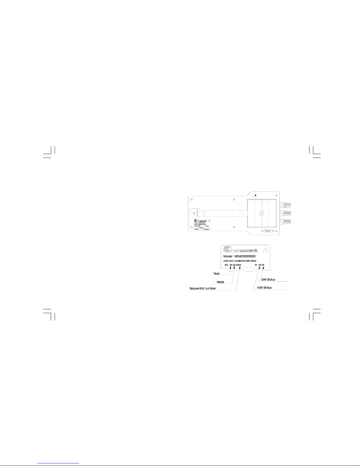
1.7 IDENTIFICATION LABEL
The instrument identification label is located externally on the housing.
It contains the following information:
M20-e-1.p65 7/9/01, 2:39 PM12
Page 13
13
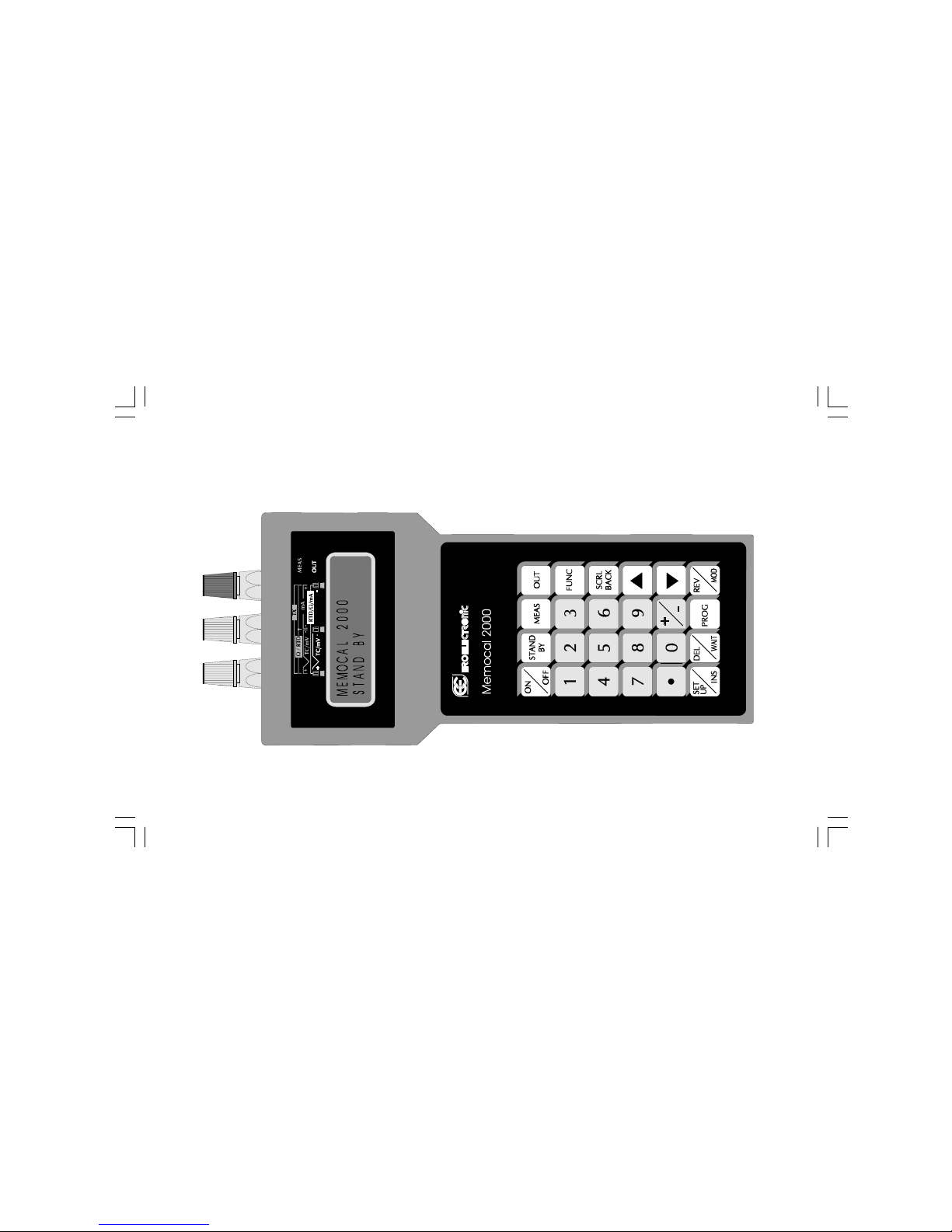
2.1 FRONT PANEL DESCRIPTION
SECTION 2 INSTRUMENT CONFIGURATION
M20-e-2.p65 7/9/01, 2:40 PM13
Page 14
14
2.2 KEYBOARD DESCRIPTION
It allows to turn ON or OFF the instrument.
This key has 2 different functions:
1) When the instrument operates in NORMAL
DISPLAY MODE, a fast depression of the pushbutton will turn ON or OFF the display
backlighting. The instrument has an internal 30
seconds time out, 3 sec only when battery is
"low". If no one of the push-buttons have been
depressed in the meantime, then the
backlighting will turn OFF automatically.
2) By keeping depressed this push-button for 1,5
seconds the instrument returns in
STAND BY mode.
It is used to start a measuring sequence.
It is used to start a generating sequence.
Push-button from to are used to set all the
numerical values.
It sets the sign of the numerical value (for numerical data entry in generation and for scalable values)
It inserts the decimal point (for numerical data entry
in generation and for scalable values).
During setting procedures, this key allows the
storage of the desired value or the desired menu
selection and then to step to the next parameter.
During program execution, this key allows to jump to
the next program step.
During setting procedures, it allows scrolling back
the menu selection without storage of settings.
During program execution, this key allows to jump
immediately to the previous program step.
During measurement, it is used to display the
maximum peak value.
By depressing it a second time, it toggles to the
normal measured value.
During generation, by keeping it depressed, it
M20-e-2.p65 7/9/01, 2:40 PM14
Page 15
15
Used to select the desired program for running,
editing or deleting
During a scaled measurement or a scaled generation, it is used to revert the display from the
normalized value to the actual electrical value and
vice versa.
During program editing it is used to modify the
program.
This push-button is used for instrument set up.
During program editing, it inserts a new program
step.
+ During measurement, they allow to
clear the memory of the maximum peak
value.
+ During measurement, they allow to
clear the memory of the minimum peak
value.
+ During measurement, they allow to
clear both of the above.
2.3 INSTRUMENT CONFIGURATION
overimposes a ramp to the generated value with a
gradient of 1 LSD for each 1/2 second; by depressing it once, the generated output will increase of 1
LSD.
During a selection procedure, it is used to move the
cursor forward.
During measurement, it is used to display the
minimum peak value.
By depressing it a second time, it toggles to the
normal measured value.
During generation, by keeping it depressed, it
overimpose a ramp to the generated value with a
gradient of 1 LSD for each 1/2 second; by depressing it once, the generated output will decrease of 1
LSD.
During a selection procedure, it is used to move the
cursor backward.
During editing of a numerical value, it deletes the
typed value.
During program editing, it deletes the whole program,
a single step or a numerical value.
While a program is running, this push-button, once
depressed, enables/disables the WAIT function.
M20-e-2.p65 7/9/01, 2:40 PM15
Page 16
16
At the first start up of the instrument or when it is desired to modify
a configuration parameter proceed as follows.
The instrument should be in STAND BY mode or in NORMAL
DISPLAY MODE.
Depress the SET UP/INS push-button. The display will show the
following:
This instrument is capable to performing, during TC and RTD
measurement, an open input test (the instrument injects a 100 mA
impulse signal).
When this test is desired, select YES and depress the FUNC pushbutton.
The display will show:
Where :
SERIAL LINK
To enable the serial communication.
DIGITAL INP
To enable the logic inputs.
NONE
Both options are disabled.
2.3.1 SERIAL LINK
RS-232 connection diagram
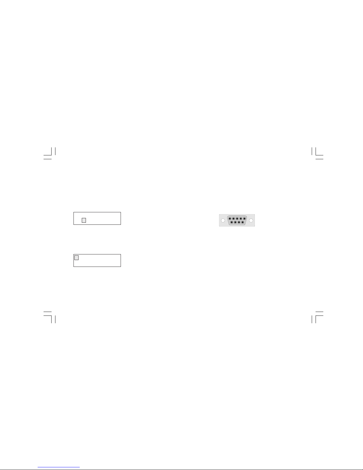
Pin Description
1 RESERVED
2 - RS232 receiver data (RX)
- Logic input 1 (step advance)
3 RS232 transmitter data (TX)
4 Positive voltage for logic input
5 Signal ground for RS232
6 RESERVED
7 RTS Request to send (used by the RS 232/RS485
converter).
8 Logic input 2 (RUN/WAIT)
9 RESERVED
OPEN INPUT TEST?
YES NO
SERIAL LINK
DIGITAL INP NONE
5 4 3 2 1
9 8 7 6
M20-e-2.p65 7/9/01, 2:40 PM16
Page 17
17
WARNING: to avoid damage to the instrument, pin 1, 6 and 9 must
be ever disconnected (we suggest the use of the "connection cable
for PC" supplied with the instrument)
Selecting the SERIAL LINK and depressing the FUNC push-button,
the display will show the following:
where:
AD is the address of the serial communication interface (from 1
to 255 ).
BR is the communication baud rate (600, 1200, 2400, 4800,
9600, 19200).
XBUS Shows the desired communication protocol (MBUS = Mode
bus or JBUS = Jbus).
PA is the communication parity control (NONE, EVEN, ODD).
With the s or t push-buttons modify the numerical values, while,
with FUNC push-button, go to the following field.
AD XX BR XXXXX
XBUS PA XXXX
2.3.2 DIGITAL INPUTS
WARNING: to avoid damage to the instrument, pin 1, 6 and 9 must
be ever disconnected.
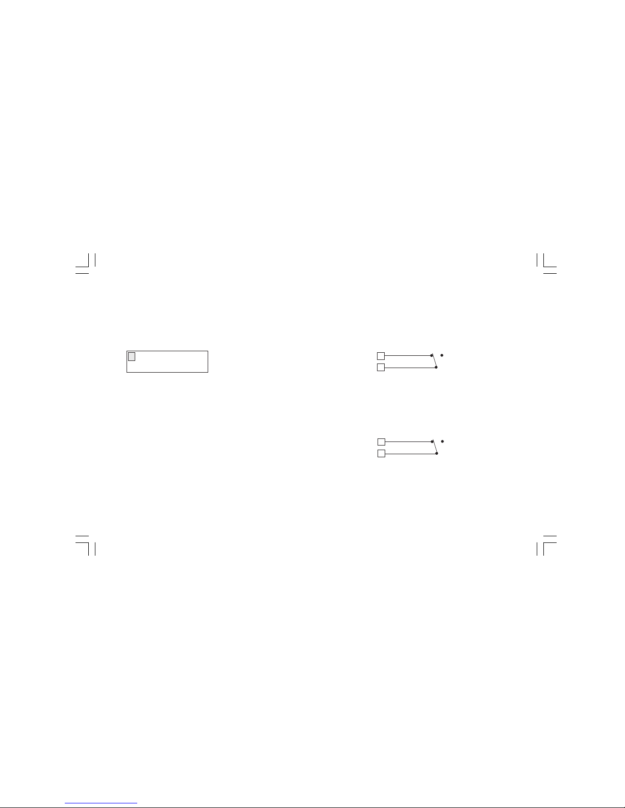
DIGITAL INPUT 1
During a sequential function routine execution, when the instrument
detects a transition from OFF to ON of the logic input 1, it will stop
to execute the actual step and will start immediately to execute the
next step (STEP ADVANCE) of the selected sequential function
routine.
DIGITAL INPUT 2
During a sequential function routine execution, it allows to stop
(WAIT) or to continue (RUN) the routine execution.
When the logic input 2 is in ON condition, the routine execution is in
WAIT status.
When the logic input 2 is in OFF condition, the routine execution is
in RUN status.
8
4
OFF
ON
2
4
OFF
ON
M20-e-2.p65 7/9/01, 2:40 PM17
Page 18

18
NOTE: when the logic inputs are selected, the WAIT function can
be enabled/disabled by logic input 2 only.
2.3.3 NONE
When NONE is selected no option will be used and the instrument
goes automatically to the next configuration step
After option selection and its parameter setting, the display will
show the following:
Select the desired default engineering unit.
Depressing the FUNC push-button.
The display will show the following:
Select the derired standard for TC and RTD measure and generation.
Depressing the FUNC push-button.
DEFAULT ENG.UNIT
°C °F
The configuration procedure is completed and the instrument will
memorize the new configuration parameters and goes automatically to the STAND BY mode.
NOTE: It is possible to stop the configuration procedure in any
moment by pushing SET UP/INS pushbutton. The instrument will
memorize the new setting followed by FUNC pushbutton pressure
and it will use the old values for all the other parameters.
TEMP. STANDARD
IPTS-68 ITS-90
M20-e-2.p65 7/9/01, 2:40 PM18
Page 19

19
4) RUN (it is running a routine).
5) EDIT (the user is editing a routine).
In the following pages each mode will be described completely.
3.1.2 GENERAL NOTES
1) The I/O impedance of the instrument will be equal to:
a) high impedance (>500 KOhm) for STAND BY mode, EDIT
mode, mV, V or TC measurement;
b) low impedance for mA measurement and Ohm simulation;
c) current injection for resistance or RTD measurement;
d) low impedance with 24 V power supply for TX measurement.
e) During RUN mode the I/O impedance will be in accordance
with the programmed action.
2) When the transfer from MEAS to OUT is requested, the
instrument goes automatically in STAND BY mode in order to
assure an high impedance during instrument connection.
3.1.3 GENERAL NOTES ON GENERATIONS
1) During generation, when a new value is desired, it is sufficient to
type directly the new value using the numerical keyboard and to
push the FUNC push-button. The instrument will start immediately to generate the new value.
2) By pushing s or t push-button, the generated value will be
increased or decreased of 1 LSD.
3) By pushing continuously s or t push-button, the generated
value will change with a rate equal to 2 LSD/second.
4) When, typing a value, an error occurs, push the DEL push-button
and retype the desired value.
SECTION 3 - OPERATING INSTRUCTIONS
3.1 PRELIMINARY
1) In order to assure the maximum accuracy of the instrument it is
necessary to perform a 3 minutes warm-up period before to start
to calibrate.
2) For all TC measurements and simulations and for mV measurements and generations it is suggested to connect the cables
directly to the instrument connectors without any additional plug.
If plugs are required, it is necessary to use gold plated banana
plugs in order to avoid not desired junctions between the cables
and the plug material.
3) For all ranges, it is suggested to use No 20 AWG (0,597 mm2 )
or larger wires.
3.1.1 OPERATIVE MODE
At power up, the instrument starts in stand by mode (warm-up with
low power consumption) and the display will show:
The instrument may be operative in one of the 5 following modes:
1) STAND BY (warm-up with low power consumption)
2) MEASURE (it is performing a measure)
3) GENERATION (it is performing a generation)
MEMOCAL 2000
STAND BY
M20-e-3.p65 7/9/01, 2:40 PM19
Page 20

20
5) When a negative value is desired, it is possible to depress the [+/
-] push-button at any time during data entry procedure.
6) Setting a numerical value out of the selected range, the instru-
ment will show "E" and it will continue to generate the old value.
7) Setting a value with a number of decimal figures higher than the
selected range, the instrument will truncate the programmed
value according to the number of decimal figures of the selected
range.
8) When it is selected a generation with automatic range selection
and a value higher than 20000 counts is programmed (the
decimal point position have no influence), the instrument will
show the "E" message and it will continue to generate the old
value.
NOTE: only the OUT 20 mA NON RANGEABLE selection allows
to set a (and to generate) a value up to 21.000 mA.
GENERAL NOTES ON MEASUREMENTS
1) During a measurement, the maximum and minimum data hold
functions are enabled.
These functions are activated automatically by measuring
function.
To display the maximum and minimum data hold push, respectively, the s and t push-button.
The instrument will show, on the right hand of the value, the PKH
message when the maximum data hold value is shown or PKL
message when the minimum data hold is shown.
When it is desired to clear the values of the maximum or
minimum data hold previously memorized, push the DEL/WAIT
push-button and, maintaining the pressure, push, respectively,
the s or t push-button.
2) The instrument incorporates, for mV, mA and TX measurements
with programmable scaling, a special function REV/MODE that
allows to display, temporaneously, the measured value without
scaling (in mV or mA).
To enable or disable this function push the REV/MODE pushbutton.
M20-e-3.p65 7/9/01, 2:40 PM20
Page 21
21
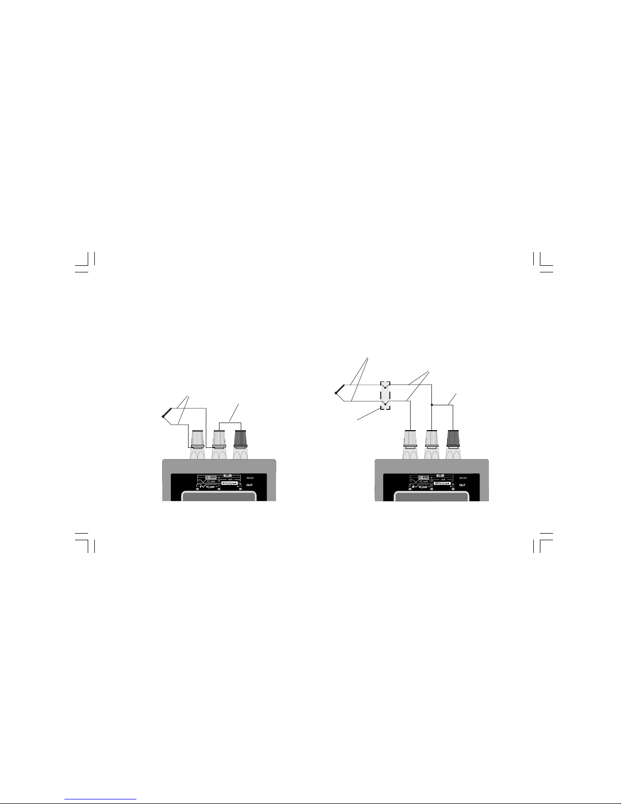
CONNECTION FOR TC MEASUREMENTS USING EXTERNAL
RJ
When a TC with external stable reference junction box is used,
connect the copper cable of the stable reference junction box to the
instrument and set the external reference junction compensation
value as shown below.
3.2 TC MEASUREMENTS
NOTES: 1) to enable/disable the open input test, see the para-
graph "2.3 INSTRUMENT CONFIGURATION".
2) The instrument will operate in accordance to the selected
temperature standard (IPTS-68 or ITS-90) (see paragraph "2.3 INSTRUMENT CONFIGURATION").
CONNECTION FOR TC MEASUREMENTS USING INTERNAL RJ
For all TC measurements it is suggested to connect the cables
directly to the instrument connectors without any additional plug.
If plugs are required, it is necessary to use gold plated banana
plugs in order to avoid not desired junction effects between cables
and plug material.
Short circuit for
open input test
+
-
TC extension
cable
+
-
Short circuit for
open input test
copper cable
TC extension cable
external reference
junction box
M20-e-3.p65 7/9/01, 2:40 PM21
Page 22
22
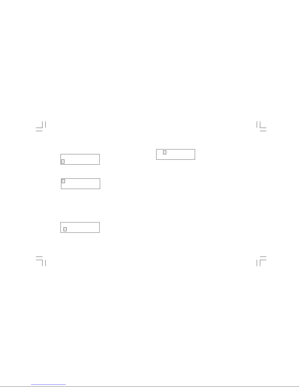
HOW TO MEASURE A TEMPERATURE USING A TC SENSOR
Depress the MEAS push-button, the display will show the following:
By s or t push-buttons select the desired input sensor, that is
"TC".
Push the FUNC push-button; the display will show the following:
By depressing the s or t push-buttons select the desired TC type
(e.g. J).
NOTE: when ITS-90 is selected, the TC type U and L are not
available so that the instrument will show this two TC type with a
small letter and it does not allow to select it by jumping the two
symbols during the cursor scroling.
Depress the FUNC push-button again the display will show the
following:
By pushing the s or t push-buttons select the desired engineering
unit (e.g. °C).
Push the FUNC push-button; the display will show the following:
Depressing the s or t push-button, select the desired cold
junction compensation type (external or internal) (e.g. INT).
NOTE
A)When the internal cold junction compensation has been selected,
the instrument uses an internal RTD to compensate the
ambient temperature (from 0 to 45 °C or from 32 to 113 °F) and it
starts immediately to display the measured value.
B)If, otherwise, the external cold junction compensation has been
selected, the instrument requires to insert the external reference
junction compensation value (the temperature of the external
reference junction compensation box).
This value can be programmed:
- from -20 °C to +80 °C or -4.0 °F to 176.0 °F for TC type J, K, T,
E, R, S, U, L, PLII;
- from 0 °C to 80 °C or from 32 °F to 176 °F for TC type B, N, Ni/
Ni18%Mo, W, W3 and W5 .
By the numerical keyboard, set the desired compensation value
(if no value is inserted, the instrument will use a value equal to 0
°C or 32 °F according to the engineering unit previously selected).
MEAS
TC RTD mA mV TX
K J L E T U W W3
S R B N P Nm W5
ENGINEERING UNIT
°C °F
CJ INT
CJ EXT XXXXX
M20-e-3.p65 7/9/01, 2:40 PM22
Page 23
23
Push the FUNC push-button, the instrument will show the following:
Where :
MEAS shows that the instrument is performing a measurement.
68 shows that the selected standard is the IPTS-68
J shows that the input sensor is a TC type J.
E shows that an external compensation has been selected
25.0 shows the selected compensation value.
XXXXXXX This field displays the measured value in engineering
units.
°C shows the selected engineering unit.
3.3 RTD MEASUREMENTS
NOTE: The instrument will operate in accordance to the selected
temperature standard (IPTS-68 or ITS-90) (see paragraph
"2.3 INSTRUMENT CONFIGURATION").
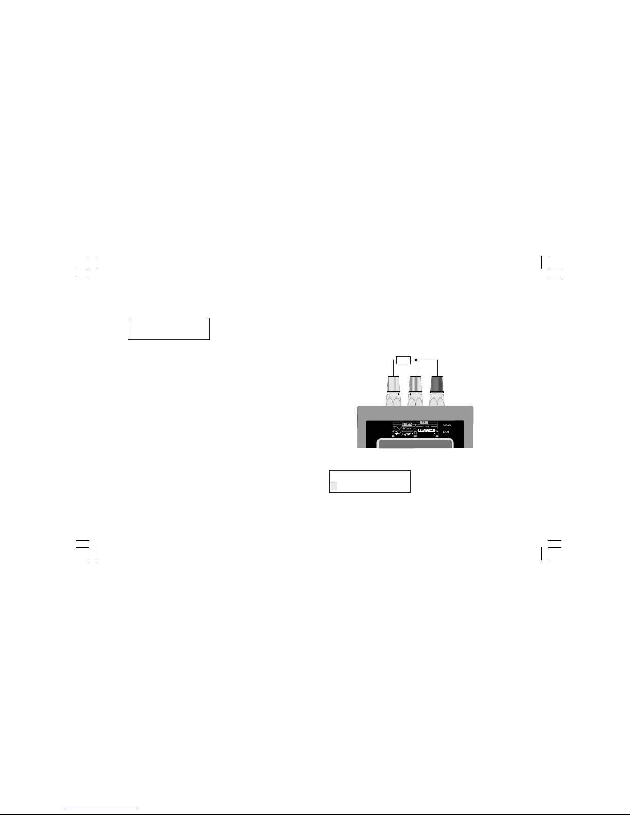
CONNECTION FOR RTD MEASUREMENTS
HOW TO MEASURE A TEMPERATURE USING AN RTD SENSOR
Push MEAS push-button; the display will show the following:
By pushing s or t push-button, select the desired input type, that
is "RTD".
MEAS 68J E 25.0
XXXXXXX °C
RTD
MEAS
TC RTD mA mV TX
M20-e-3.p65 7/9/01, 2:40 PM23
Page 24
24
Push the FUNC push-button; the display will show:
By pushing s or t push-button, select the desired RTD type (e.g.
Pt100).
NOTE: when ITS-90 is selected, the RTD type Ni 100 is not
available so that the instrument will show this RTD with small
letters and it does not allow to select it.
Push the FUNC push-button; the display will show the following:
Depressing s or t push-button, select the desired engineering
unit (e.g. °C).
Depress the FUNC push-button; the display will show the following:
where:
MEAS shows that the instrument is performing a measurement
68 shows that the selected standard is the IPTS-68
Pt100 shows that the input sensor is an RTD Pt 100.
XXXXXXX it shows the measured value.
°C shows the selected engineering unit.
Pt100 Ni100
Ohm
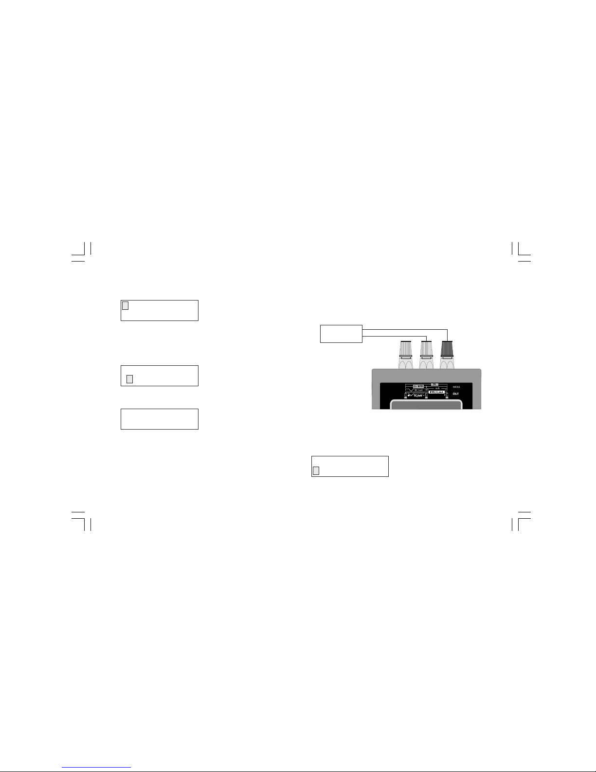
3.4 - mA MEASUREMENT.
CONNECTION FOR mA MEASUREMENTS WITHOUT AUXILIARY POWER SUPPLY.
NOTE: The MEMOCAL 2000 Input impedance is equal to 10 W.
HOW TO MEASURE A mA SIGNAL
Push the MEAS push-button; the display will show:
MEAS
TC RTD mA mV TX
+
-
mA
GENERATOR
ENGINEERING UNIT
°C °F
MEAS 68 Pt100
XXXXXXX °C
M20-e-3.p65 7/9/01, 2:40 PM24
Page 25

25
Pushing s or t push-button select the desired input type, that is
"mA".
Push the FUNC push-button; the display will show the following:
Where:
NON - RANGEABLE
allows to select a mA measurement without scaling (with a read-out
in mA).
RNG(L)
allows to select a mA input with read-out scaling (the read-out is
expressed in engineering unit and not in mA).
RNG( )
allows to select a mA input with square root extraction on the
measured value and programmable read-out scale in engineering
units.
3.4.1 - NON RANGEABLE - mA measurement without scaling
Pushing s or t push-button, select the NON RANGEABLE input
type.
Push the FUNC push-button.
The display will show:
Where :
20, 200 show the selectable 20mA, 200mA fix ranges.
Note: the 200 mA is limited at 130 mA.
When a fixed range is selected the instrument will use a fix
decimal figures.
AUTO
indicates that the instrument automatically selects the proper
input range in order to measure the input signal with the max.
possible resolution.
Pushing s or t push-button select the desired input range (e.g.
AUTO)
Push the FUNC push-button.
The instrument starts measuring and the display will show:
Where:
MEAS indicates that the instrument is performing a measurement.
AUTO shows that the autoranging function is selected.
mA is the engineering unit.
XXXXX shows the measured value.
NON - RANGEABLE
RNG(L) RNG( )
MEAS AUTO
XXXXXX mA
20 200
AUTO
M20-e-3.p65 7/9/01, 2:40 PM25
Page 26

26
3.4.2 - RNG(L) linear mA measurement with read-out scaling.
The RNG(L) selection allows to associate to an input range the
desired read-out range.
Example 1: with a linear input range from 0 to 20 mA it is desired
to have a read-out going from -10.000 to 10.000 (m/s).
Pushing s or t push-button, select the desired function, that is
RNG (L).
Push the FUNC push-button, the display will show the following:
By the numerical keyboard, set the desired initial scale value (For
Example 1, this value is equal to 0.000 mA).
NOTES:
1) The value assigned to "H.RANGE mA" must be higher than the
value assigned to "L.RANGE mA" parameter.
2) The value assigned to "H.RANGE EU" parameter must be
different from the value assigned to "L.RANGE EU".
When conditions 1 or 2 are not satisfied, the instrument will reject
the new value showing the "0" and it will maintain the cursor on the
rejected parameter.
3) The value assigned to "H.RANGE EU" parameter can be lower
than the value assigned to "L.RANGE EU" (reverse read-out).
Push the FUNC push-button; the cursor will go automatically to the
lower line.
By the numerical keyboard, set the desired read-out assigned to
the initial scale value (For Example 1, it is equal to -10.000 m/s).
Depress the FUNC push-button.
NOTES: For the read-out in eng. units, the number of decimal
figures is free with respect of the read-out limits (20000 counts).
The display will show the following:
By the numerical keyboard, set the desired final scale value (For
Example 1, this value is equal to 20.000 mA).
Push the FUNC push-button.
By the numerical keyboard, set the desired read-out assigned to
the final scale value (For Example 1 this value is equal to 10.000
m/s).
Push the FUNC push-button.
NOTE For the read-out in eng. units, the number of decimal figures
will be equal to the decimal figure programmed in "L.RNG
EU".
The instrument will start to measure and, for Example 1, if a 3 mA
signal is applied to the input terminal the display will show:
L.RNG XXXXXX mA
L.RNG XXXXXX EU
H.RNG XXXXXX mA
H.RNG XXXXXX EU
M20-e-3.p65 7/9/01, 2:40 PM26
Page 27

27
NOTES:
1) The instrument will automatically select the input range containing the two programmed values ("L.RANGE mA" and "H.RANGE
mA") with the maximum resolution.
2) During mA measurement with programmable read-out scaling it is
possible to enable/disable, by the REV/MOD push-button, the
scaling function and to display the measured value in mA.
3) During mA measurement, the instrument is able to measure and
display up to 5 % more than the upper programmed value or 5%
less than the lower programmed value.
3.4.3 - RNG ( ) - mA measurement with square root extraction
and linear read-out scaling.
Selecting the RNG ( ) option, the instrument extracts the square
root of the measured value and scales it according to the programmed range.
Example 2 : with a quadratic input range from 4 to 20 mA it is
desired to have a read-out going from 5.00 to 200.00 (m3/h).
Pushing s or t push-button, select the RNG( ) function.
MEAS RNG(L)mA
-3.000 EU
Push the FUNC push-button, the display will show the following:
By the numerical keyboard, set the desired initial scale value (For
Example 2 it is equal to 4.000 mA).
NOTES:
1) The value assigned to "H.RANGE mA" must be higher than the
value assigned to "L.RANGE mA" parameter.
2) The value assigned to "H.RANGE EU" parameter must be
different from the value assigned to "L.RANGE EU".
When conditions 1 or 2 are not satisfied, the instrument will reject
the new value showing the "0" and it will maintain the cursor on the
rejected parameter.
3) The value assigned to "H.RANGE EU" parameter can be lower
than the value assigned to "L.RANGE EU" (reverse read-out).
Push the FUNC push-button; the cursor will go automatically to the
lower line.
By the numerical keyboard, set the desired read-out assigned to
the initial scale value (For Example 2, it is equal to 5.00 m3/h.)
Depress the FUNC push-button.
NOTES:
1) The input range may contain negative values.
2) The displayed range will only be represented with positive
numbers.
L.RNG XXXXXX mA
L.RNG XXXXXX EU
M20-e-3.p65 7/9/01, 2:40 PM27
Page 28

28
The display will show the following:
By the numerical keyboard, set the desired final scale value (For
Example 2 it is equal to 20.000 mA).
Push the FUNC push-button.
By the numerical keyboard, set the desired read-out assigned to
the final scale value (For Example 2 it is equal to 200.00 (m3/h).
Push the FUNC push-button.
NOTES:
1) For the read-out in eng. units, the number of decimal figures will
be equal to the decimal figure programmed in "L.RNG EU".
2) For the read-out in eng. units, the number of decimal figures is
free with respect of the read-out limits (20000 counts).
The instrument will start to measure and, for Example 2, if a 7 mA
signal is applied to the input terminal the display will show:
NOTES:
1) The instrument will automatically select the input range containing the two programmed values ("L.RANGE mA" and "H.RANGE
mA") with the maximum resolution.
2) During mA measurement with programmable read-out scaling it is
possible to enable/disable, by the REV/MOD push-button, the
scaling function and to display the measured value in mA.
3) During mA measurement, the instrument is able to measure and
display up to 5 % more than the upper programmed value or 5%
less than the lower programmed value.
H.RNG XXXXXX mA
H.RNG XXXXXX EU
MEAS RNG( )mA
86.71 EU
M20-e-3.p65 7/9/01, 2:40 PM28
Page 29
29
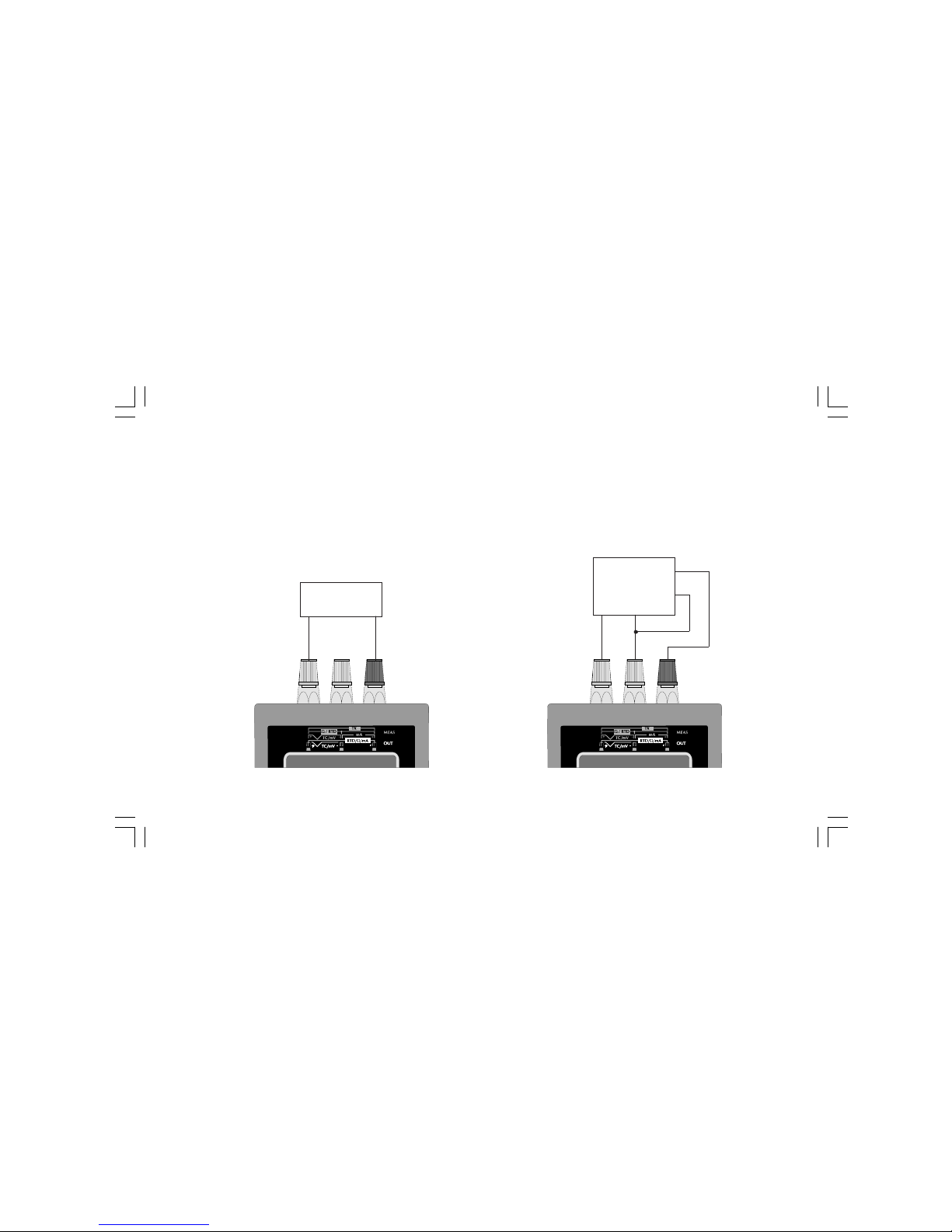
CONNECTION FOR TX MEASUREMENTS FROM 3 OR 4-WIRE
TRANSMITTER WITH 24 V POWER SUPPLY.
3.5 - TX MEASUREMENT
NOTE: we define as TX all the 2, 3 or 4 -wire transmitters with 20
mA output capability.
The instrument generates a 24 V (max 25 mA) auxiliary
power supply for the transmitters in subject.
CONNECTION FOR TX MEASUREMENTS FROM 2-WIRE
TRANSMITTER WITH 24 V POWER SUPPLY.
TX
+
-
Maximum current: 25 mA
+
Maximum current: 25 mA
TX
-
PWS
Measure
+
-
+
M20-e-3.p65 7/9/01, 2:40 PM29
Page 30

30
HOW TO EXECUTE A TX MEASUREMENT.
Push the MEAS push-button; the display will show:
Pushing s or t push-button, select the TX measurement.
Push the FUNC push-button; the display will show the following:
Where:
RNG(L)
means a linear input with programmable read-out scale in engineering units.
RNG( )
means a square root extraction of the measured value with
programmable read-out scale in engineering units .
3.5.1 RNG (L) TX measurement with linear input and
read-out scaling.
Example 1: with a linear input range from 4 to 20 mA it is desired
to have a read-out going from 1.00 to 10.00 (Bar).
Pushing s or t push-button select the RNG(L) scaling type.
Push the FUNC push-button, the display will show the following:
By the numerical keyboard, set the desired initial scale value (from
Example 1, this value is equal to 4.000 mA).
NOTES:
1) The value assigned to "H.RANGE mA" must be higher than the
value assigned to "L.RANGE mA" parameter.
2) The value assigned to "H.RANGE EU" parameter must be
different from the value assigned to "L.RANGE EU".
When conditions 1 or 2 are not satisfied, the instrument will reject
the new value showing the "0" and it will maintain the cursor on the
rejected parameter.
3) The value assigned to "H.RANGE EU" parameter can be lower
than the value assigned to "L.RANGE EU" (reverse read-out).
Push the FUNC push-button; the cursor will go automatically on the
lower line.
By the numerical keyboard, set the desired read-out assigned to the
initial scale value (from Example 1 this value is equal to 1.00 Bar).
Depress the FUNC push-button.
NOTES: The instrument uses the 20 mA input range.
For the read-out in eng. units, the number of decimal figures is free
with respect of the read-out limits (20000 counts).
MEAS
TC RTD mA mV TX
RNG(L)
RNG( )
L.RNG XXXXXX mA
L.RNG XXXXXX EU
M20-e-3.p65 7/9/01, 2:40 PM30
Page 31

31
The display will show the following:
By the numerical keyboard, set the desired final scale value (From
Example 1, this value is equal to 20.000 mA).
Push the FUNC push-button; the cursor will go automatically on the
lower line.
By the numerical keyboard, set the desired read-out assigned to the
final scale value (from Example 1 this value is equal to 10.00 Bar).
NOTE: For the read-out in eng. units, the number of decimal
figures will be equal to the decimal figure programmed in
"L.RANGE EU".
Push the FUNC push-button.
The instrument will start to measure .
For example 1, if a signal equal to 13.067 mA is applied to the input
terminal the display will show:
NOTES:
1) During a TX measurement it is possible to enable/disable, by
the REV/MOD push-button, the scaling function and to display
the measured value in mA. For the previous indication the
instrument will show:
2) During TX measurement, the instrument is able to measure and
display up to 5 % more than the upper programmed value or 5%
less than the lower programmed value.
3.5.2 RNG ( ) TX measurement with square root extraction on
the measured value and programmable read-out
scaling.
Selecting the RNG ( ) option, the instrument extracts the square
root of the measured value and scales it according to the programmed range.
Example 2: with a quadratic input range from 4 to 20 mA it is
desired to have a linear read-out going from 0.0 to 500.0 (l/h).
Pushing s or t push-button select the RNG ( ) scaling type.
Push the FUNC push-button, the display will show the following:
H.RNG XXXXXX mA
H.RNG XXXXXX EU
MEAS TX(L)
6.10 EU
MEAS 20 mA
13.067 mA
L.RNG XXXXXX mA
L.RNG XXXXXX EU
M20-e-3.p65 7/9/01, 2:40 PM31
Page 32

32
By the numerical keyboard, set the desired initial scale value (from
Example 2, this value is equal to 4.000 mA).
NOTES:
1) The value assigned to "H.RANGE mA" must be higher than the
value assigned to "L.RANGE mA" parameter.
2) The value assigned to "H.RANGE EU" parameter must be
different from the value assigned to "L.RANGE EU".
When conditions 1 or 2 are not satisfied, the instrument will reject
the new value showing the "0" and it will maintain the cursor on the
rejected parameter.
3) The value assigned to "H.RANGE EU" parameter can be lower
than the value assigned to "L.RANGE EU" (reverse read-out).
Push the FUNC push-button; the cursor will go automatically on the
lower line.
By the numerical keyboard, set the desired read-out assigned to the
initial scale value (for Example 2 this value is equal to 0.0 l/h).
Depress the FUNC push-button.
NOTES:
1) The displayed range will only be represented with positive
numbers.
2) The instrument selects the 20 mA input range.
3) For the read-out in eng. units, the number of decimal figures is free
with respect of the read-out limits (20000 counts).
The display will show the following:
By the numerical keyboard, set the desired final scale value (For
Example 2, this value is equal to 20.000 mA).
Push the FUNC push-button; the cursor will go automatically on the
lower line.
By the numerical keyboard, set the desired read-out assigned to
the final scale value (for Example 2, this value is equal to 500.0l/h).
NOTE: For the read-out in eng. units, the number of decimal
figures will be equal to the decimal figure assigned to
"L.RANGE EU".
Push the FUNC push-button.
The instrument will start to measure .
For example 2, if a signal equal to 9.718 mA is applied to the input
terminal the display will show:
NOTES:
1) During a TX measurement it is possible to enable/disable, by
the REV/MOD push-button, the scaling function and to display
the measured value in mA.
2) During TX measurement, the instrument is able to measure and
display up to 5 % more than the upper programmed value or 5%
less than the lower programmed value.
H.RNG XXXXXX mA
H.RNG XXXXXX EU
MEAS TX( )
298.9 EU
M20-e-3.p65 7/9/01, 2:40 PM32
Page 33
33
3.6 - mV MEASUREMENT.
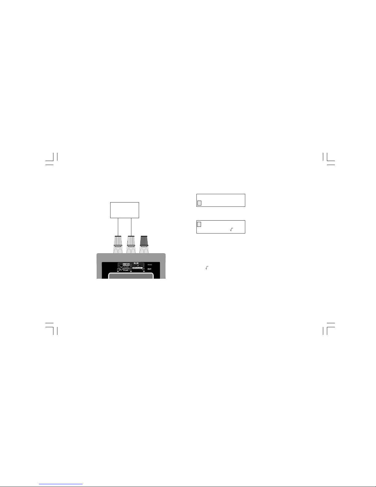
CONNECTION FOR mV MEASUREMENTS
NOTE: The input impedance of the MEMOCAL 2000 is:
- up to 2 V, the input imped. is > 10 MW
- from 2 V to 20 V, the input imped. is = 500 kW.
HOW TO MEASURE A mV SIGNAL
Push the MEAS push-button; the display will show:
Pushing s or t push-button select the "mV" input type.
Push the FUNC push-button; the display will show the following:
Where:
NON - RANGEABLE
allows to select a mV measurement without scaling (with a read-out
in mV).
RNG(L)
allows to select a mV input with linear scaling on the read-out (the
read-out is expressed in engineering unit and not in mV).
RNG( )
allows to select a mV input with square root extraction on the
measured value and programmable read-out scale in engineering
units.
+
-
mV
GENERATOR
MEAS
TC RTD mA mV TX
NON - RANGABLE
RNG(L) RNG( )
M20-e-3.p65 7/9/01, 2:40 PM33
Page 34

34
3.6.1 - NON RANGEABLE - mV measurement without scaling
Pushing s or t push-button, select the NON RANGEABLE input
type.
The display will show:
Where :
20, 200, 2000 , 20000
show that a fix range is desired.
These values are selectable and have the following significance:
20mV, 200mV, 2000mV, 20000mV f.s.
When a fixed range is selected the instrument will use a fix
decimal figures.
AUTO
indicates that the instrument automatically selects the proper
input range in order to measure the input signal with the max.
possible resolution.
Pushing s or t push-button select the desired input range (e.g.
AUTO)
Push the FUNC push-button.
The instrument starts measuring and the display will show:
Where:
MEAS indicates that the instrument is performing a measurement.
AUTO shows that the autoranging function is selected.
mV is the engineering unit.
XXXXX shows the measured value.
3.6.2 - RNG(L) mV measurement with linear read-out scaling.
The RNG(L) selection allows to associate to an input range the
desired read-out range.
Example 1: with a linear input range from 0 V to 10 V it is desired
to have a read-out going from -100.0 to 1000.0 (mBar).
Pushing s or t push-button, select the RNG (L) function.
Push the FUNC push-button, the display will show the following:
By the numerical keyboard, set the desired initial scale value (For
Example 1, this value is equal to 0 mV).
NOTES:
1) The value assigned to "H.RANGE mV" must be higher than the
value assigned to "L.RANGE mV" parameter.
2) The value assigned to "H.RANGE EU" parameter must be
different from the value assigned to "L.RANGE EU".
20 200 2000
20000 AUTO
MEAS AUTO
XXXXXX mV
L.RNG XXXXXX mV
L.RNG XXXXXX EU
M20-e-3.p65 7/9/01, 2:40 PM34
Page 35

35
When conditions 1 or 2 are not satisfied, the instrument will reject
the new value showing the "0" and it will maintain the cursor on the
rejected parameter.
3) The value assigned to "H.RANGE EU" parameter can be lower
than the value assigned to "L.RANGE EU" (reverse read-out).
Push the FUNC push-button; the cursor will go automatically on the
lower line.
By the numerical keyboard, set the desired read-out assigned to
the initial scale value (For Example 1, it is equal to -100.0 mBar).
Depress the FUNC push-button.
NOTES: For the read-out in eng. units, the number of decimal
figures is free with respect of the read-out limits (20000 counts).
The display will show the following:
By the numerical keyboard, set the desired final scale value (For
Example 1, this value is equal to 10000 mV).
Push the FUNC push-button.
By the numerical keyboard, set the desired read-out assigned to
the final scale value (For Example 1 this value is equal to 1000.0
mBar).
Push the FUNC push-button.
NOTE For the read-out in eng. units, the number of decimal figures will
be equal to the decimal figure programmed in "L.RNG EU".
The instrument will start to measure and, for Example 1, if a 3 V
signal is applied to the input terminal the display will show:
NOTES:
1) The instrument will automatically select the input range containing the two programmed values ("L.RANGE mV" and "H.RANGE
mV") with the maximum resolution.
2) During mV measurement with programmable read-out scaling it is
possible to enable/disable, by the REV/MOD push-button, the
scaling function and to display the measured value in mV.
3) During mV measurement, the instrument is able to measure and
display up to 5 % more than the upper programmed value or 5%
less than the lower programmed value.
3.6.3 - RNG ( ) - mV measurement with square root extraction
on the measured value and read-out scaling.
Selecting the RNG ( ) option, the instrument extracts the square
root of the measured value and scales it according to the programmed range.
Example 2 : with a quadratic input range from 1 to 5 V it is desired
to have a read-out going from 0.0 to 1500.0 (m3/h).
H.RNG XXXXXX mV
H.RNG XXXXXX EU
MEAS RNG(L)mV
229.9 EU
M20-e-3.p65 7/9/01, 2:40 PM35
Page 36

36
Pushing s or t push-button, select the RNG( ) function.
Push the FUNC push-button, the display will show the following:
By the numerical keyboard, set the desired initial scale value (For
Example 2 it is equal to 1000 mV).
NOTES:
1) The value assigned to "H.RANGE mV" must be higher than the
value assigned to "L.RANGE mV" parameter.
2) The value assigned to "H.RANGE EU" parameter must be
different from the value assigned to "L.RANGE EU".
When conditions 1 or 2 are not satisfied, the instrument will reject
the new value showing the "0" and it will maintain the cursor on the
rejected parameter.
3) The value assigned to "H.RANGE EU" parameter can be lower
than the value assigned to "L.RANGE EU" (reverse read-out).
Push the FUNC push-button; the cursor will go automatically on the
lower line.
By the numerical keyboard, set the desired read-out assigned to
the initial scale value (For Example 2, it is equal to 0.0 m3/h).
Depress the FUNC push-button.
NOTES:
1) The input range may contain negative values.
2) The displayed range will only be represented with positive
numbers.
The display will show the following:
By the numerical keyboard, set the desired final scale value (For
Example 2 it is equal to 5000 mV).
Push the FUNC push-button.
By the numerical keyboard, set the desired read-out assigned to
the final scale value (For Example 2 it is equal to 1500.0 (m3/h)).
Push the FUNC push-button.
NOTE For the read-out in eng. units, the number of decimal figures will
be equal to the decimal figure programmed in "L.RNG EU".
The instrument will start to measure and, for Example 2, if a 4.5 V
signal is applied to the input terminal the display will show:
NOTES:
1) The instrument will automatically select the input range containing the two programmed values ("L.RANGE mV" and "H.RANGE
mV") with the maximum resolution.
2) During mV measurement with programmable read-out scaling it is
possible to enable/disable, by the REV/MOD push-button, the
L.RNG XXXXXX mV
L.RNG XXXXXX EU
H.RNG XXXXXX mV
H.RNG XXXXXX EU
MEAS RNG( )mV
1402.7 EU
M20-e-3.p65 7/9/01, 2:40 PM36
Page 37
37
scaling function and to display the measured value in mV.
3) During mV measurement, the instrument is able to measure and
display up to 5 % more than the upper programmed value or 5%
less than the lower programmed value.
3.7 - OHM MEASUREMENTS
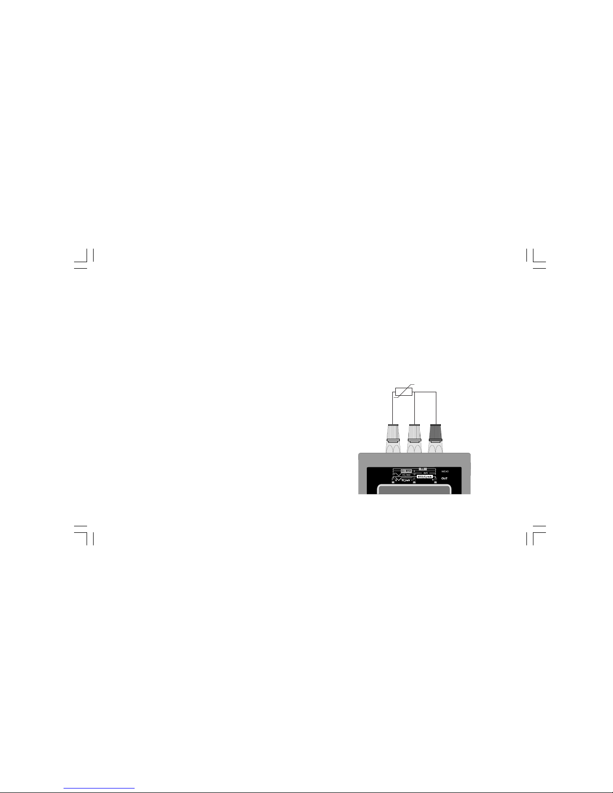
CONNECTION FOR OHM MEASUREMENTS
The short circuit between terminals B and C may be made:
A) close to the instrument; in this case the measured value is equal to
the line resistance plus the sensor resistance (i.e. potentiometer).
B) close to the sensor; in this case, the measured value will be
equal to the sensor resistance only.
The instrument is able to compensate a line resistance up to
100 Ohm/wire.
ABC
M20-e-3.p65 7/9/01, 2:40 PM37
Page 38
38
HOW TO MEASURE A RESISTANCE
Push MEAS push-button; the display will show the following:
By pushing s or t push-button, select the RTD input type.
Push the FUNC push-button; the display will show:
By pushing s or t push-button, select OHM.
Depress the FUNC push-button; the display will show the following:
where:
MEAS shows that the instrument is performing a measurement
Ohm shows that the instrument is performing an W measure-
ment.
W shows the engineering unit.
XXXXXXX shows the measured value in engineering unit.
MEAS
TC RTD mA mV TX
Pt 100 Ni 100
Ohm
MEAS Ohm
XXXXXXX W
3.8 TC SIMULATION
NOTE: The instrument will operate in accordance to the selected
temperature standard (IPTS-68 or ITS-90) (see paragraph
"2.3 INSTRUMENT CONFIGURATION").
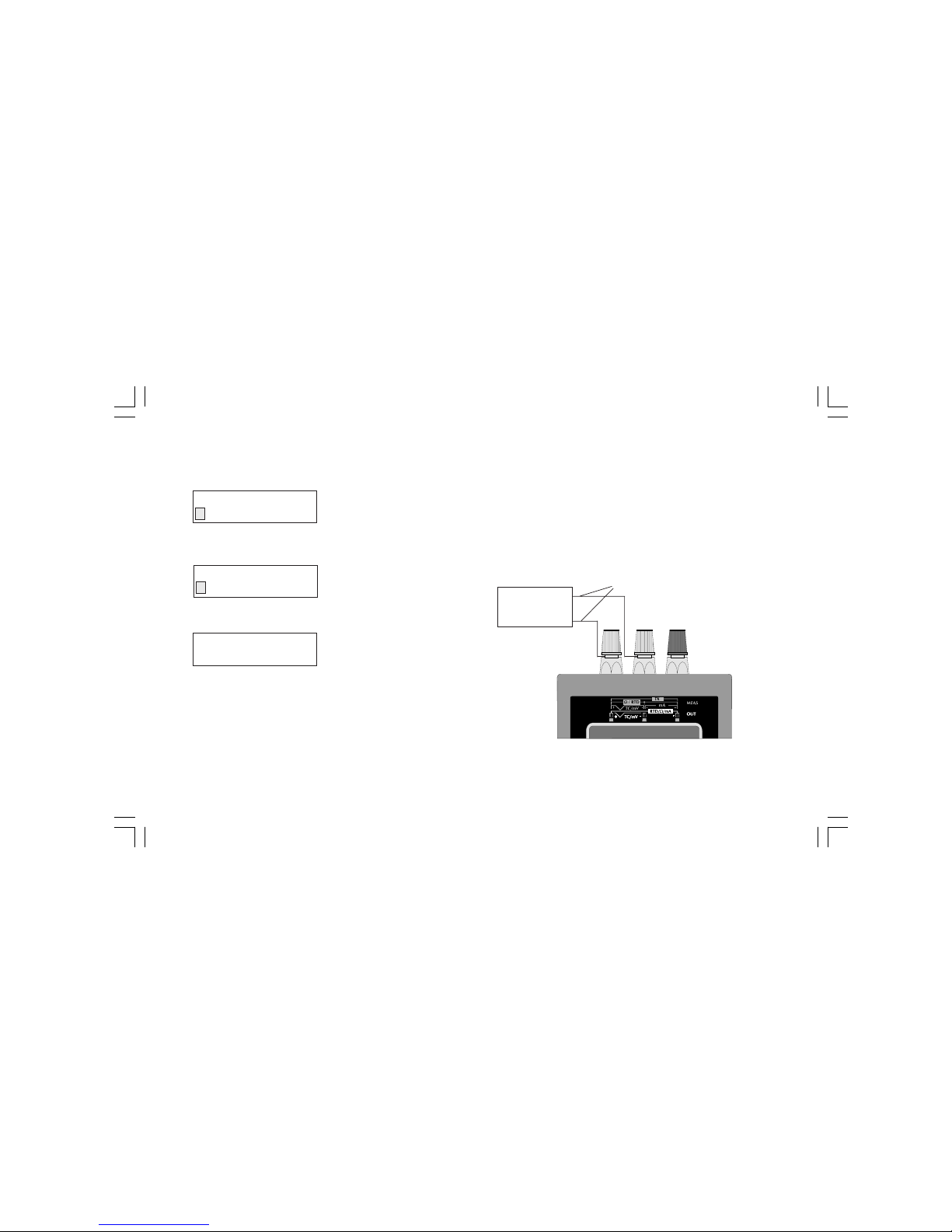
CONNECTION FOR TC SIMULATION USING INTERNAL RJ
For all TC simulations it is suggested to connect the extension cables
directly to the instrument connectors without any additional plug.
If plugs are required, it is necessary to use gold plated banana
plugs in order to avoid not desired junction effects between cables
and plug material.
NOTE: when it is desired to exclude the cold junction compensation, select the external compensation and set a value equal to 0 °C
or 32 °F.
+
-
TC extension cable
TC
MEASURING
INSTRUMENT
M20-e-3.p65 7/9/01, 2:40 PM38
Page 39
39
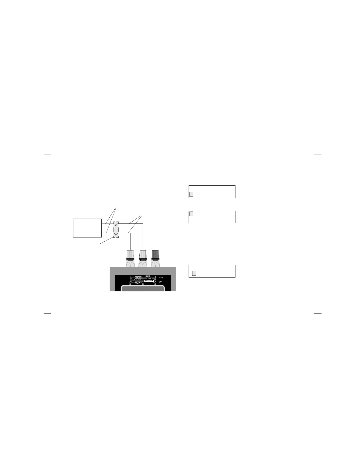
CONNECTION FOR TC SIMULATION USING EXTERNAL RJ
When it is desired to simulate a TC and an external stable reference junction box is used, connect the copper cable of the stable
reference junction box to the instrument and set the external
reference junction compensation value as show below.
HOW TO SIMULATE A TC SENSOR
Depress the OUT push-button, the display will show the following:
By s or t push-buttons select the "TC" sensor.
Push the FUNC push-button; the display will show the following:
By depressing the s or t push-buttons select the desired TC type
(e.g. J).
NOTE: when ITS-90 is selected, the TC type U and L are not
available so that the instrument will show these two TC types with a
small letter and it does not allow to select them by jumping the two
symbols during the cursor scrolling.
Depress the FUNC push-button again the display will show the
following:
By pushing the s or t push-buttons select the desired engineering
unit (e.g. °C).
+
-
copper cable
external reference
junction box
TC extension cable
TC
MEASURING
INSTRUMENT
OUT
TC RTD mA mV
K J L E T U W W3
S R B N P Nm W5
ENGINEERING UNIT
°C °F
M20-e-3.p65 7/9/01, 2:40 PM39
Page 40

40
Push the FUNC push-button; the display will show the following:
Depressing the s or t push-button, select the desired cold
junction compensation type (external or internal) (e.g. INT).
NOTE
A)When the internal cold junction compensation has been selected,
the instrument uses an internal RTD to compensate the
ambient temperature (from 0 to 45 °C or from 32 to 113 °F).
B)If, otherwise, the external cold junction compensation has been
selected, the instrument requires to insert the external reference
junction compensation value (the temperature of the external
reference junction compensation box).
This value can be programmed:
- from -20 °C to +80 °C or -4.0 °F to 176.0 °F for TC type J, K, T,
E, R, S, U, L, PLII;
- from 0 °C to 80 °C or from 32 °F to 176 °F for TC type B, N, Ni/
Ni18%Mo, W, W3 and W5 .
By the numerical keyboard, set the desired compensation value
(if no value is inserted, the instrument will use a value equal to 0
°C or 32 °F according to the engineering unit previously selected).
OUT 68J E 25.0
X °C
CJ INT
CJ EXT XXXXX
Push the FUNC push-button, the instrument will show the following:
where:
OUT shows that the instrument is performing a generation
68 shows that the selected standard is the IPTS-68
J shows that the instrument simulates a TC J.
E shows that an external compensation is selected.
25.0 shows the selected compensation value.
XXXXX this field will show the generated value in engineering units.
Type the value to be generated.
Push the FUNC push-button.
M20-e-3.p65 7/9/01, 2:40 PM40
Page 41
41
3.9 RTD SIMULATION
NOTE: The instrument will operate in accordance to the selected
temperature standard (IPTS-68 or ITS-90) (see paragraph
"2.3 INSTRUMENT CONFIGURATION").
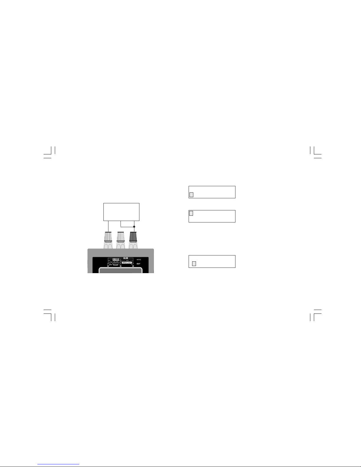
CONNECTION FOR RTD SIMULATION
NOTE: the measuring current must be higher than 100 mA and
lower than 2 mA and the polarity must be equal to the indication
shown in the drawing otherwise the instrument will generate an
error message (see chapter "ERROR MESSAGES").
HOW TO SIMULATE AN RTD SENSOR
Push OUT push-button; the display will show the following:
By pushing s or t push-button, select the "RTD" sensor.
Push the FUNC push-button; the display will show:
By pushing s or t push-button, select the desired RTD type (e.g.
Ni100).
NOTE: when ITS-90 is selected, the RTD type Ni 100 is not
available so that the instrument will show this RTD with small
letters and it does not allow to select it.
Push the FUNC push-button; the display will show the following:
Depressing s or t push-button, select the desired engineering
unit (e.g. °C).
OUT
TC RTD mA mV
Pt100 Ni100
Ohm
+
-
RTD
MEASURING
DEVICE
ENGINEERING UNIT
°C °F
M20-e-3.p65 7/9/01, 2:40 PM41
Page 42
42
Depress the FUNC push-button; the display will show the following:
where:
OUT shows that the instrument is performing a simulation
68 shows that the selected standard is the IPTS-68
Ni100 shows that the simulated sensor is an RTD Ni 100.
XXXXX it shows the simulated value.
°C shows the selected engineering unit.
Type the value to be generated.
Push the FUNC push-button.
3.9 - mA GENERATION.
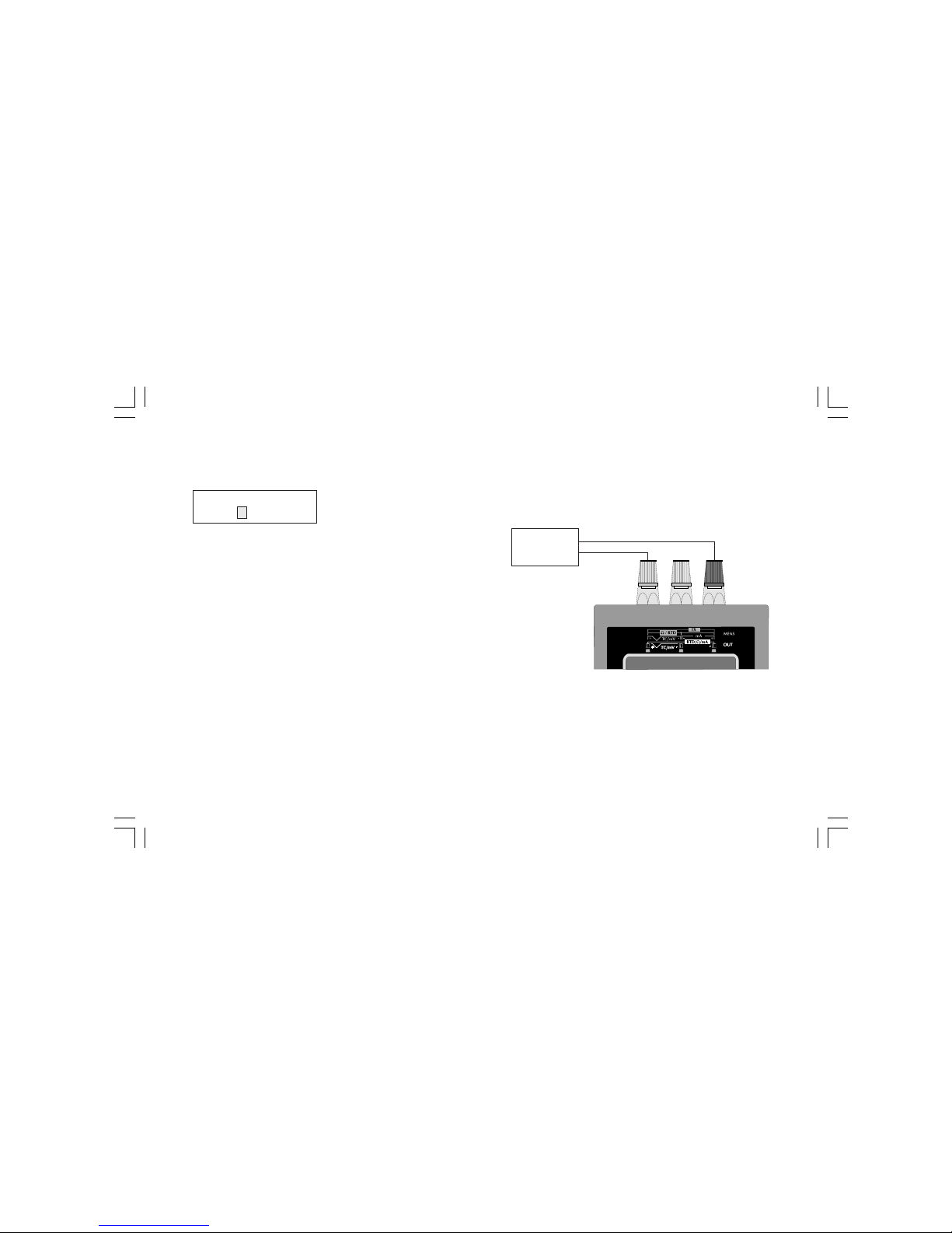
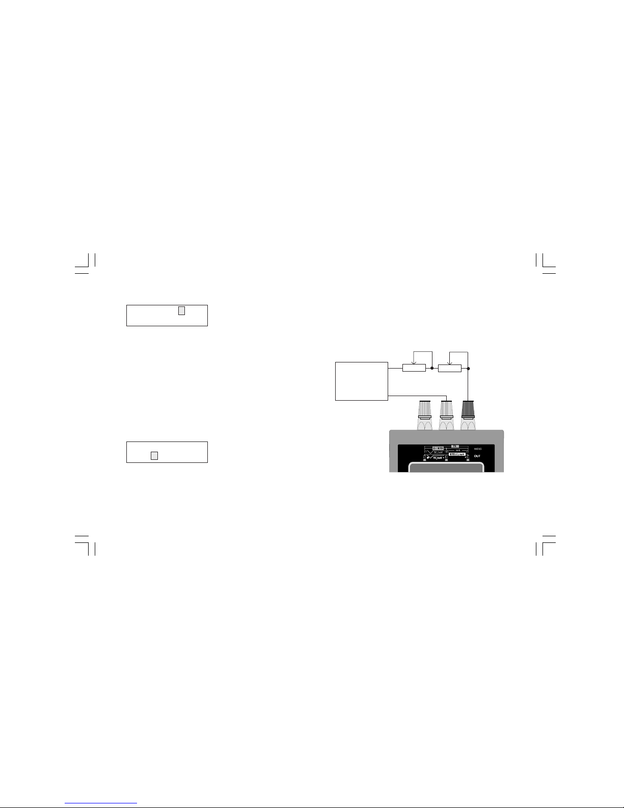
CONNECTION FOR mA GENERATION
+
mA
MEASURING
DEVICE
Maximum load 500 OHM
OUT 68 Ni100
XXXXX °C
-
M20-e-3.p65 7/9/01, 2:40 PM42
Page 43

43
HOW TO GENERATE A mA SIGNAL
Push the OUT push-button; the display will show:
Pushing s or t push-button select the "mA" output type.
Push the FUNC push-button; the display will show the following:
By this screen it is possible to select the maximum load applied to
the instrument during mA generation. Select the minimum range
encompassing the impedance of the instrument under test in order
to reduce the power consumption of the MEMOCAL.
When the load is unknown, select the 500 W in order to assure the
maximum compatibility.
NOTE: When the instrument operates without AC adapter, the first
range (100 W) is limited to 50 W maximum.
The other ranges have not additional limits.
Pushing s or t push-button select the desired output load and
push the FUNC push-button.
The display will show the following:
Where:
NON - RANGEABLE
allows to select a mA generation without scaling (with a read-out in
mA).
RNG(L)
allows to select a mA output with read-out scaling (the selection of
the value to be generated will be made in engineering unit and not
in mA).
RNG(QUAD)
allows to obtain a quadratic mA output with programmable read-out
scale in engineering units (the selection of the value to be generated
will be made in engineering unit and it will be linear while the
resulting output will be quadratic).
3.9.1 - NON RANGEABLE - mA generation without scaling
Pushing s or t push-button, select the NON RANGEABLE output
type.
Push the FUNC push-button.
The display will show:
Where:
OUT indicates that the instrument is performing a generation.
20 mA show the selected range.
OUT
TC RTD mA mV
20 mA UP TO RL=
100W 200W 500W
NON - RANGABLE
RNG(L) RNG(QUAD)
OUT 20 mA
XXXXX mA
M20-e-3.p65 7/9/01, 2:40 PM43
Page 44

44
mA is the engineering unit.
XXXXX shows the generated value.
NOTE: the OUT 20 mA NON RANGEABLE selection allows to
set (and to generate) a value up to 21.000 mA.
3.9.2 - RNG(L) linear mA generation with read-out scaling.
The RNG(L) selection allows to associate to a read-out range a
linear mA output (the selection of the value to be generated will be
made in engineering unit and not in mA).
Example 1 : with a read-out range from 0.0 to 100.0 (kg/cm2) it is
desired to obtain a linear output from 0 to 20 mA.
Pushing s or t push-button, select the RNG (L) function.
Push the FUNC push-button, the display will show the following:
By the numerical keyboard, set the desired initial scale value (For
Example 1, this value is equal to 4.000 mA).
NOTES:
1) The value assigned to "H.RANGE mA" must be higher than the
value assigned to "L.RANGE mA" parameter.
2) The value assigned to "H.RANGE EU" parameter must be
different from the value assigned to "L.RANGE EU".
When conditions 1 or 2 are not satisfied, the instrument will reject
the new value showing the "0" and it will maintain the cursor on the
rejected parameter.
3) The value assigned to "H.RANGE EU" parameter can be lower
than the value assigned to "L.RANGE EU" (reverse read-out).
Push the FUNC push-button; the cursor will go automatically on the
lower line.
By the numerical keyboard, set the desired read-out assigned to
the initial scale value (For Example 1, it is equal to 0.0 kg/cm2).
Depress the FUNC push-button.
NOTES: For the read-out in eng. units, the number of decimal
figures is free with respect of the read-out limits (20000 counts).
The display will show the following:
By the numerical keyboard, set the desired final scale value (For
Example 1, this value is equal to 20.000 mA).
Push the FUNC push-button.
By the numerical keyboard, set the desired read-out assigned to
the final scale value (For Example 1 this value is equal to 100.0 kg/
cm2).
Push the FUNC push-button.
L.RNG XXXXXX mA
L.RNG XXXXXX EU
H.RNG XXXXXX mA
H.RNG XXXXXX EU
M20-e-3.p65 7/9/01, 2:40 PM44
Page 45
45
NOTES:
1) For the read-out in eng. units, the number of decimal figures will
be equal to the decimal figure programmed in "L.RANGE EU".
2) During a mA generation with programmable read-out scaling, it is
possible to enable/disable, by the REV/MOD push-button, the
scaling function and to display the generated value in mA.
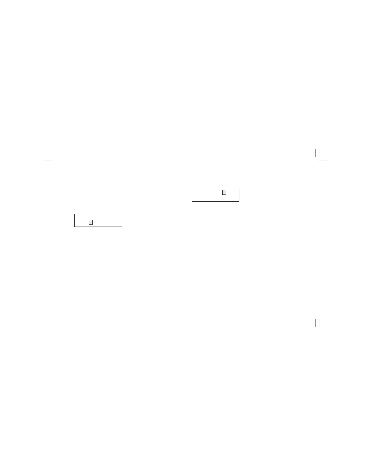
The instrument will show:
By the numerical keyboard, set the value to be generate.
Push the FUNC push-button, the instrument start immediately to
generate.
3.9.3 - RNG (QUAD) - mA generation with quadratic output and
linear read-out scaling.
Selecting the RNG (QUAD) option, the value to be generated will be
set in engineering unit and it will be linear while the resulting output
will follow quadratic curve.
Example 2 : with a quadratic output range from 4 to 20 mA it is
desired to have a read-out going from 5.00 to 200.00 (m3/h).
Pushing s or t push-button, select the RNG(QUAD) function.
Push the FUNC push-button, the display will show the following:
By the numerical keyboard, set the desired initial scale value (For
Example 2 it is equal to 4.000 mA).
NOTES:
1) The value assigned to "H.RANGE mA" must be higher than the
value assigned to "L.RANGE mA" parameter.
2) The value assigned to "H.RANGE EU" parameter must be
different from the value assigned to "L.RANGE EU".
When conditions 1 or 2 are not satisfied, the instrument will reject
the new value showing the "0" and it will maintain the cursor on the
rejected parameter.
3) The value assigned to "H.RANGE EU" parameter can be lower
than the value assigned to "L.RANGE EU" (reverse read-out).
Push the FUNC push-button; the cursor will go automatically on the
lower line.
By the numerical keyboard, set the desired read-out assigned to
the initial scale value (For Example 2, it is equal to 5.00 m3/h.)
Depress the FUNC push-button.
NOTES: The displayed range will only be represented with positive
numbers.
The display will show the following:
OUT RNG(L) mA
XXXXXX EU
L.RNG XXXXXX mA
L.RNG XXXXXX EU
M20-e-3.p65 7/9/01, 2:40 PM45
Page 46
46
By the numerical keyboard, set the desired final scale value (For
Example 2 it is equal to 20.000 mA).
Push the FUNC push-button.
By the numerical keyboard, set the desired read-out assigned to
the final scale value (For Example 2 it is equal to 200.00 m3/h).
NOTES:
1) For the read-out in eng. units, the number of decimal figures will
be equal to the decimal figure programmed in "L.RNG EU".
2) For the read-out in eng. units, the number of decimal figures is
free with respect of the read-out limits (20000 counts).
3) During mA generation with programmable read-out scaling it is
possible to enable/disable, by the REV/MOD push-button, the
scaling function and to display the generation value in mA.
Push the FUNC push-button; the display will show:
By the numerical keyboard, set the value to be generate.
Push the FUNC push-button, the instrument start immediately to
generate.
3.10 - TX SIMULATION
NOTE: we define as TX all the 2, 3 or 4 -wire transmitters with 20
mA output capability.
CONNECTION FOR 2-WIRE TX SIMULATION.
For both potentiometers it is suggested to utilize 10 turn, 2 W,
linear potentiometers with the resistance shown in figure.
OUT RNG(QUAD) mA
XXXXXX EU
+
-
mA MEASURING
DEVICE
WITH AUXILIARY
POWER SUPPLY
1K W
10K W
Fast
Accurate
H.RNG XXXXXX mA
H.RNG XXXXXX EU
M20-e-3.p65 7/9/01, 2:40 PM46
Page 47

47
NOTE FOR 3 OR 4-WIRE TX SIMULATION
When a 3 or 4 wire TX simulation is required, it is sufficient to
ignore the power supply of the instrument under test and to connect
and program the calibrator as for standard mA generation (see
chapter 3.9).
HOW TO EXECUTE A 2-WIRE TX SIMULATION.
Push the MEAS push-button; the display will show:
Pushing s or t push-button select the "mA" input type.
Push the FUNC push-button; the display will show the following:
Where:
NON - RANGEABLE
allows to select a mA measurement without scaling (with a read-out
in mA).
RNG(L)
allows to select a mA input with read-out scaling (the read-out is
expressed in engineering unit and not in mA).
RNG( )
allows to select a mA input with square root extraction on the
measured value and programmable read-out scale in engineering
units.
3.10.1 - NON RANGEABLE - TX simulation without scaling
Example 1: it is desired to simulate a 2-wire, 4 to 20 mA transmitter
while the "mA measuring device with auxiliary power supply" is
programmed for a read-out going from -10.000 to 10.000 (m/s).
Pushing s or t push-button, select the NON RANGEABLE input
type.
Push the FUNC push-button.
The display will show:
Where :
20, 200 show the selectable 20mA, 200mA fix ranges.
Note: the 200 mA is limited at 130 mA.
When a fixed range is selected the instrument will use a fix
decimal figures.
AUTO
indicates that the instrument automatically selects the proper
input range in order to measure the input signal with the max.
possible resolution.
MEAS
TC RTD mA mV TX
NON - RANGEABLE
RNG(L) RNG( )
20 200
AUTO
M20-e-3.p65 7/9/01, 2:40 PM47
Page 48

48
Pushing s or t push-button select the desired input range (e.g.
AUTO)
Push the FUNC push-button.
The instrument starts measuring and the display will show:
Where:
MEAS indicates that the instrument is performing a measurement.
AUTO shows that the autoranging function is selected.
XXXXX shows the measured value.
mA is the engineering unit.
The two potentiometers allow to change the load of the instrument
under test in order to make the measuring current equal to the
desired value while the MEMOCAL 2000 is used to measure, with
high accuracy, the current in subject.
3.10.2 - RNG(L) TX simulation with read-out scaling.
The RNG(L) selection allows to associate to an input range in mA
the desired read-out range.
Example 2: it is desired to simulate a 2-wire transmitter with a
linear output range from 4 to 20 mA while the "mA measuring
device with auxiliary power supply" is programmed for a read-out
going from 0.000 to 20.000 (rpm) and it is desired to have on the
device and on the calibrator the same read-out scaling.
Pushing s or t push-button, select the RNG (L) function.
Push the FUNC push-button, the display will show the following:
By the numerical keyboard, set the desired initial scale value (For
Example 2, this value is equal to 4.000 mA).
NOTES:
1) The value assigned to "H.RANGE mA" must be higher than the
value assigned to "L.RANGE mA" parameter.
2) The value assigned to "H.RANGE EU" parameter must be
different from the value assigned to "L.RANGE EU".
When conditions 1 or 2 are not satisfied, the instrument will reject
the new value showing the "0" and it will maintain the cursor on the
rejected parameter.
3) The value assigned to "H.RANGE EU" parameter can be lower
than the value assigned to "L.RANGE EU" (reverse read-out).
Push the FUNC push-button; the cursor will go automatically on the
lower line.
By the numerical keyboard, set the desired read-out assigned to
the initial scale value (For Example 2, it is equal to 0.000 rpm).
Depress the FUNC push-button.
NOTES: For the read-out in eng. units, the number of decimal
MEAS AUTO
XXXXXX mA
L.RNG XXXXXX mA
L.RNG XXXXXX EU
M20-e-3.p65 7/9/01, 2:40 PM48
Page 49

49
figures is free with respect of the read-out limits (20000 counts).
The display will show the following:
By the numerical keyboard, set the desired final scale value (For
Example 2, this value is equal to 20.000 mA).
Push the FUNC push-button.
By the numerical keyboard, set the desired read-out assigned to the
final scale value (For Example 2 this value is equal to 20.000 rpm).
Push the FUNC push-button.
NOTE For the read-out in eng. units, the number of decimal figures will
be equal to the decimal figure programmed in "L.RNG EU".
The instrument will start to measure and, for Example 2, if a 13 mA
signal is applied to the input terminal the display will show:
NOTES:
1) The instrument will automatically select the input range containing the two programmed values ("L.RANGE mA" and "H.RANGE
mA") with the maximum resolution.
2) During mA measurement with programmable read-out scaling it is
possible to enable/disable, by the REV/MOD push-button, the
scaling function and to display the measured value in mA.
3) During mA measurement, the instrument is able to measure and
display up to 5 % more than the upper programmed value or 5%
less than the lower programmed value.
The two potentiometers allow to change the load of the instrument
under test in order to make the measure of the MEMOCAL 2000
equal to the desired value and to verify the indication of the
instrument under test.
3.10.3 - RNG ( ) - TX simulation with square root extraction
and linear read-out scaling.
Selecting the RNG ( ) option, the instrument extracts the square
root of the measured value and scales it according to the programmed range.
Example 3: it is desired to simulate a 2-wire transmitter with a
quadratic output range from 4 to 20 mA the "mA measuring device
with auxiliary power supply" is programmed for a read-out going
from 5.00 to 200.00 (m3/h) but it is desired to have on the device
and on the calibrator the same read-out scaling.
Pushing s or t push-button, select the RNG( ) function.
Push the FUNC push-button, the display will show the following:
H.RNG XXXXXX mA
H.RNG XXXXXX EU
MEAS RNG(L)mA
11249 EU
M20-e-3.p65 7/9/01, 2:40 PM49
Page 50

50
By the numerical keyboard, set the desired initial scale value (For
Example 3 it is equal to 4.000 mA).
NOTES:
1) The value assigned to "H.RANGE mA" must be higher than the
value assigned to "L.RANGE mA" parameter.
2) The value assigned to "H.RANGE EU" parameter must be
different from the value assigned to "L.RANGE EU".
When conditions 1 or 2 are not satisfied, the instrument will reject
the new value showing the "0" and it will maintain the cursor on the
rejected parameter.
3) The value assigned to "H.RANGE EU" parameter can be lower
than the value assigned to "L.RANGE EU" (reverse read-out).
Push the FUNC push-button; the cursor will go automatically on the
lower line.
By the numerical keyboard, set the desired read-out assigned to
the initial scale value (For Example 3, it is equal to 5.00 m3/h.)
Depress the FUNC push-button.
NOTES:
1) The input range may contain negative values.
2) The displayed range will only be represented with positive
numbers.
The display will show the following:
By the numerical keyboard, set the desired final scale value (For
Example 3 it is equal to 20.000 mA).
Push the FUNC push-button.
By the numerical keyboard, set the desired read-out assigned to
the final scale value (For Example 3 it is equal to 200.00 (m2/h).
Push the FUNC push-button.
NOTES:
1) For the read-out in eng. units, the number of decimal figures will
be equal to the decimal figure programmed in "L.RNG EU".
2) For the read-out in eng. units, the number of decimal figures is
free with respect of the read-out limits (20000 counts).
The instrument will start to measure and, for Example 3, if a 7 mA
signal is applied to the input terminal the display will show:
NOTES:
1) The instrument will automatically select the input range containing the two programmed values ("L.RANGE mA" and "H.RANGE
mA") with the maximum resolution.
L.RNG XXXXXX mA
L.RNG XXXXXX EU
H.RNG XXXXXX mA
H.RNG XXXXXX EU
MEAS RNG( )mA
86.68 EU
M20-e-3.p65 7/9/01, 2:40 PM50
Page 51
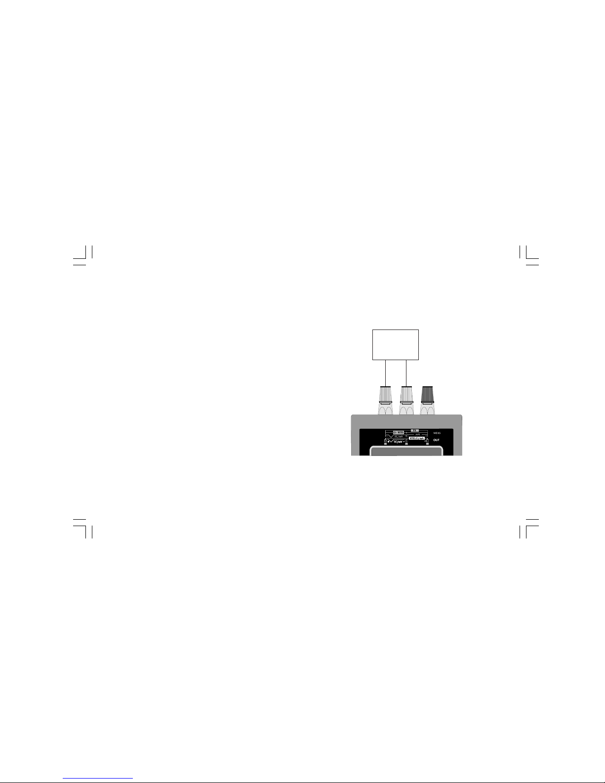
51
2) During mA measurement with programmable read-out scaling it is
possible to enable/disable, by the REV/MOD push-button, the
scaling function and to display the measured value in mA.
3) During mA measurement, the instrument is able to measure and
display up to 5 % more than the upper programmed value or 5%
less than the lower programmed value.
3.11 - mV GENERATION.
CONNECTION FOR mV GENERATION
NOTE: The minimum load for mV generation is:
- up to 200 mV, it must be > 1 MW
- from 200 mV to 20 V, it must be > 100 kW.
-
+
mV
MEASURING
DEVICE
M20-e-3.p65 7/9/01, 2:40 PM51
Page 52
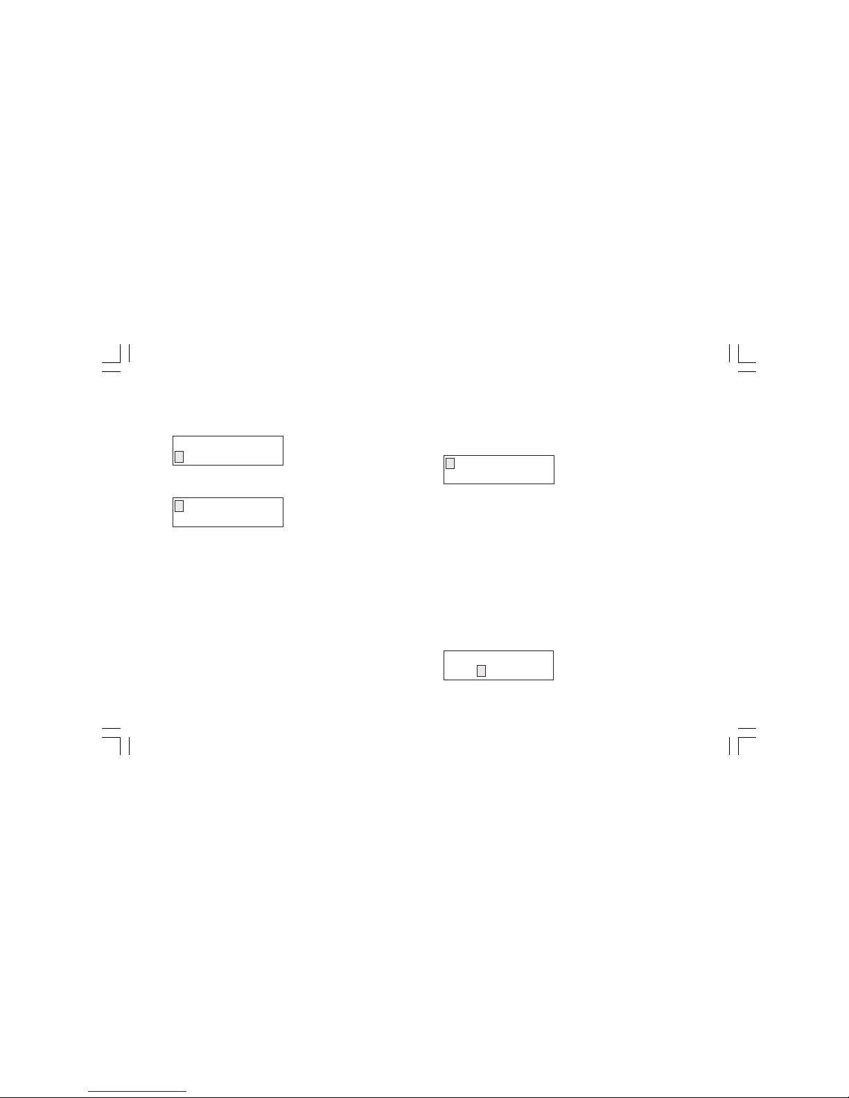
52
HOW TO GENERATE A mV SIGNAL
Push the OUT push-button; the display will show:
Pushing s or t push-button select the "mV" output type.
Push the FUNC push-button; the display will show the following:
Where:
NON - RANGEABLE
allows to select a mV generation without scaling (the value to be
generate will be set in mV).
RNG(L)
allows to select a mV output with linear scaling on the read-out (the
value to be generated will be set in engineering unit and not in mV).
RNG(QUAD)
allows to select a mV output with quadratic output and programmable read-out scale in engineering units (the value to be
generate will be set in engineering unit and it will be linear while
the resulting output will be quadratic).
3.11.1 - NON RANGEABLE - mV generation without scaling
Pushing s or t push-button, select the NON RANGEABLE output
type.
The display will show:
Where :
20, 200, 2000 , 20000
show that a fix range is desired.
These values are selectable and have the following significance:
20mV, 200mV, 2000mV, 20000mV f.s.
When a fixed range is selected the instrument will use a fix
decimal figures.
AUTO
indicates that the instrument automatically selects the proper
output range in order to generate the programmed signal with the
max. available accuracy.
Pushing s or t push-button select the desired output range (e.g.
AUTO)
Push the FUNC push-button.
The instrument needs the value to be generate.
The instrument will show:
OUT
TC RTD mA mV
NON - RANGEABLE
RNG(L) RNG(QUAD)
20 200 2000
20000 AUTO
OUT AUTO mV
XXXXXX mV
M20-e-3.p65 7/9/01, 2:41 PM52
Page 53

53
Where:
OUT indicates that the instrument is performing a generation.
AUTO indicates the autoranging function.
XXXXX it shows the programmed value.
mV is the engineering unit.
By the numerical keyboard, set the value to be generate.
Push the FUNC push-button, the instrument start immediately to
generate.
3.11.2 - RNG(L) mV generation with linear read-out scaling.
The RNG(L) selection allows to associate to a read-out range a
desired linear output range.
Example 1: with a read-out going from -100.0 to 1000.0 (mB) it is
desired to generate a linear output from 0 V to 10 V.
Pushing s or t push-button, select the RNG (L) function.
Push the FUNC push-button, the display will show the following:
By the numerical keyboard, set the desired initial scale value (For
Example 1, this value is equal to 0 mV).
NOTES:
1) The value assigned to "H.RANGE mV" must be higher than the
value assigned to "L.RANGE mV" parameter.
2) The value assigned to "H.RANGE EU" parameter must be
different from the value assigned to "L.RANGE EU".
When conditions 1 or 2 are not satisfied, the instrument will reject
the new value showing the "0" and it will maintain the cursor on the
rejected parameter.
3) The value assigned to "H.RANGE EU" parameter can be lower
than the value assigned to "L.RANGE EU" (reverse read-out).
Push the FUNC push-button; the cursor will go automatically on the
lower line.
By the numerical keyboard, set the desired read-out assigned to
the initial scale value (For Example 1, it is equal to -100.0 mB).
Depress the FUNC push-button.
NOTES: For the read-out in eng. units, the number of decimal
figures is free with respect of the read-out limits (20000 counts).
The display will show the following:
By the numerical keyboard, set the desired final scale value (For
Example 1, this value is equal to 10000 mV).
Push the FUNC push-button.
By the numerical keyboard, set the desired read-out assigned to the
final scale value (For Example 1 this value is equal to 1000.0 mB).
L.RNG XXXXXX mV
L.RNG XXXXXX EU
H.RNG XXXXXX mV
H.RNG XXXXXX EU
M20-e-3.p65 7/9/01, 2:41 PM53
Page 54

54
Push the FUNC push-button.
NOTE For the read-out in eng. units, the number of decimal figures will
be equal to the decimal figure programmed in "L.RNG EU".
The instrument will show:
By the numerical keyboard, set the value to be generate.
Push the FUNC push-button, the instrument start immediately to
generate.
NOTES:
1) The instrument will automatically select the output range
containing the two programmed values ("L.RANGE mV" and
"H.RANGE mV") with the maximum resolution.
2) During mV generation with programmable read-out scaling it is
possible to enable/disable, by the REV/MOD push-button, the
scaling function and to display the generated value in mV.
3) During mV generation, the instrument is able to generate and
display up to 5 % more than the upper programmed value or 5%
less than the lower programmed value.
3.11.3 - RNG (QUAD) - mV generation with quadratic output and
linear read-out scaling.
Selecting the RNG (QUAD) option, the value to be generated will be
set in engineering unit and it will be linear while the resulting output
will be quadratic.
Example 2 : with a linear read-out going from 0.0 to 1500.0 (m3/h)
it is desired to obtain a quadratic output range from 1 to 5 V.
Pushing s or t push-button, select the RNG(QUAD) function.
Push the FUNC push-button, the display will show the following:
By the numerical keyboard, set the desired initial scale value (For
Example 2 it is equal to 1000 mV).
NOTES:
1) The value assigned to "H.RANGE mA" must be higher than the
value assigned to "L.RANGE mA" parameter.
2) The value assigned to "H.RANGE EU" parameter must be
different from the value assigned to "L.RANGE EU".
When conditions 1 or 2 are not satisfied, the instrument will reject
the new value showing the "0" and it will maintain the cursor on the
rejected parameter.
3) The value assigned to "H.RANGE EU" parameter can be lower
than the value assigned to "L.RANGE EU" (reverse read-out).
OUT RNG(L) mV
XXXXXX EU
L.RNG XXXXXX mV
L.RNG XXXXXX EU
M20-e-3.p65 7/9/01, 2:41 PM54
Page 55

55
Push the FUNC push-button; the cursor will go automatically on the
lower line.
By the numerical keyboard, set the desired read-out assigned to
the initial scale value (For Example 2, it is equal to 0.0 m3/h).
Depress the FUNC push-button.
NOTES:
1) The output range may contain negative values.
2) The displayed range will only be represented with positive
numbers.
The display will show the following:
By the numerical keyboard, set the desired final scale value (For
Example 2 it is equal to 5000 mV).
Push the FUNC push-button.
By the numerical keyboard, set the desired read-out assigned to
the final scale value (For Example 2 it is equal to 1500.0 (m3/h)).
Push the FUNC push-button.
NOTES:
1) The instrument will automatically select the output range
containing the two programmed values ("L.RANGE mV" and
"H.RANGE mV") with the maximum resolution.
2) For the read-out in eng. units, the number of decimal figures will
be equal to the decimal figure programmed in "L.RANGE EU".
3) By keeping depressed the s and/or t push-button it
overimposes a ramp up or down to the generated value with a
gradient of 2 LSD/second.
4) During a mV generation with programmable read-out scaling, it is
possible to enable/disable, by the REV/MOD push-button, the
scaling function and to display the generated value in mV.
The instrument will show:
By the numerical keyboard, set the value to be generate.
Push the FUNC push-button, the instrument start immediately to
generate.
H.RNG XXXXXX mV
H.RNG XXXXXX EU
OUT RNG(QUAD) mV
XXXXXX EU
M20-e-3.p65 7/9/01, 2:41 PM55
Page 56
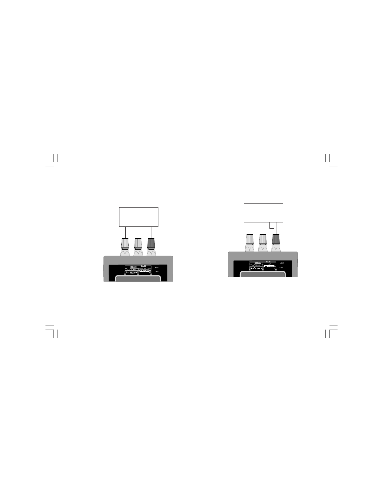
56
3.12 - OHM SIMULATION
2-WIRE CONNECTION FOR OHM SIMULATION
NOTE: for all ohm simulation, the measuring current must be
higher than 100 mA, lower than 2 mA and having the polarity shown
in the figure; otherwise the instrument could show an error
message (see chapter ERROR MESSAGES).
3-WIRE CONNECTION FOR OHM SIMULATION
W
MEASURING
DEVICE
+
-
From 15 to 500 OHM
W
MEASURING
DEVICE
+
-
From 15 to 500 OHM
M20-e-3.p65 7/9/01, 2:41 PM56
Page 57
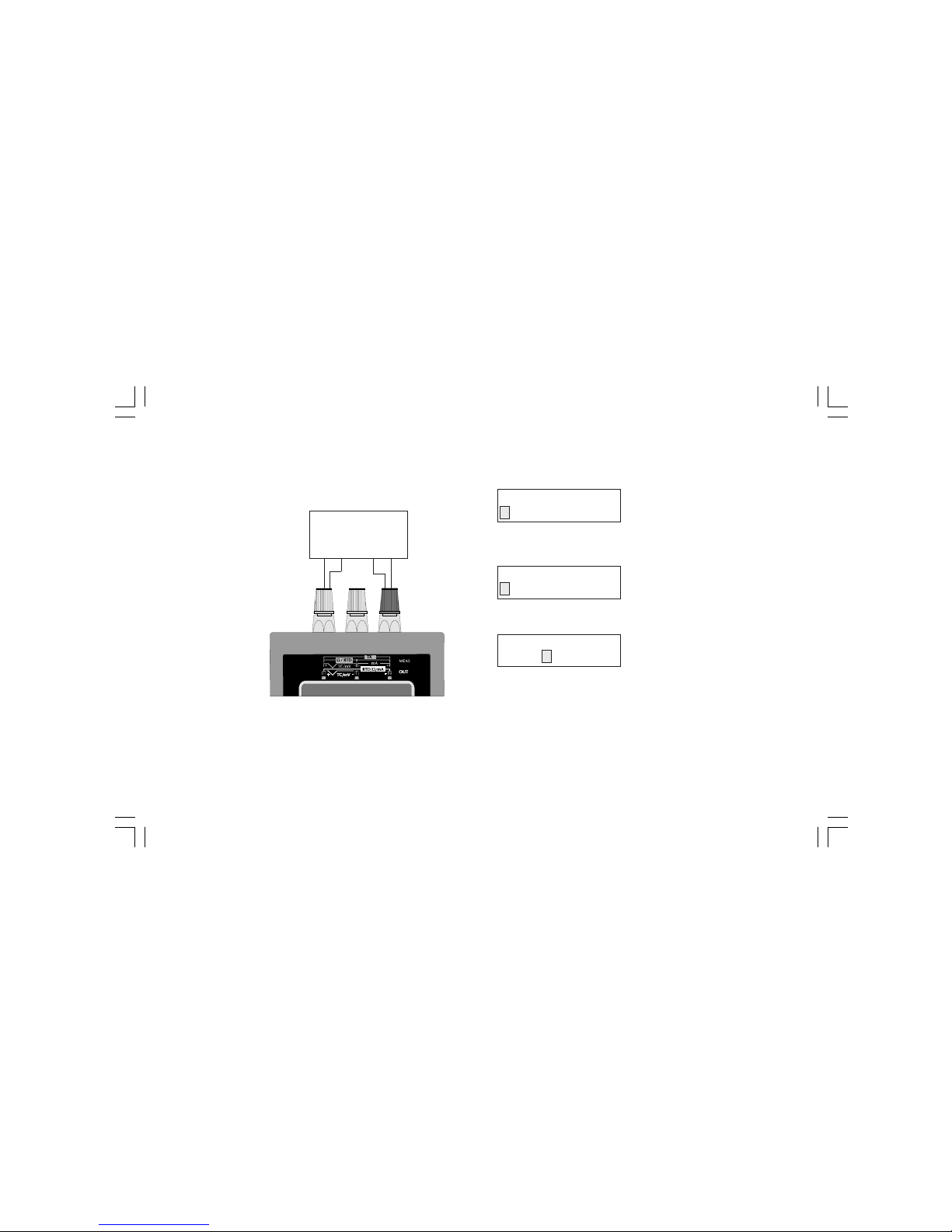
57
4-WIRE CONNECTION FOR OHM SIMULATION HOW TO SIMULATE A RESISTANCE
Push OUT push-button; the display will show the following:
By pushing s or t push-button, select the RTD input type.
Push the FUNC push-button; the display will show:
By pushing s or t push-button, select OHM.
Depress the FUNC push-button; the display will show the following:
where:
OUT shows that the instrument is performing a simulation.
Ohm shows that the instrument is performing an W simulation.
W shows the engineering unit.
XXXXXXX shows the programmed value in engineering unit.
Type the desired value.
Push the FUNC push-button.
The instrument start immediately to simulate.
W
MEASURING
DEVICE
+
-
From 15 to 500 OHM
OUT
TC RTD mA mV
Pt 100 Ni 100
Ohm
OUT Ohm
XXXXXXX W
M20-e-3.p65 7/9/01, 2:41 PM57
Page 58
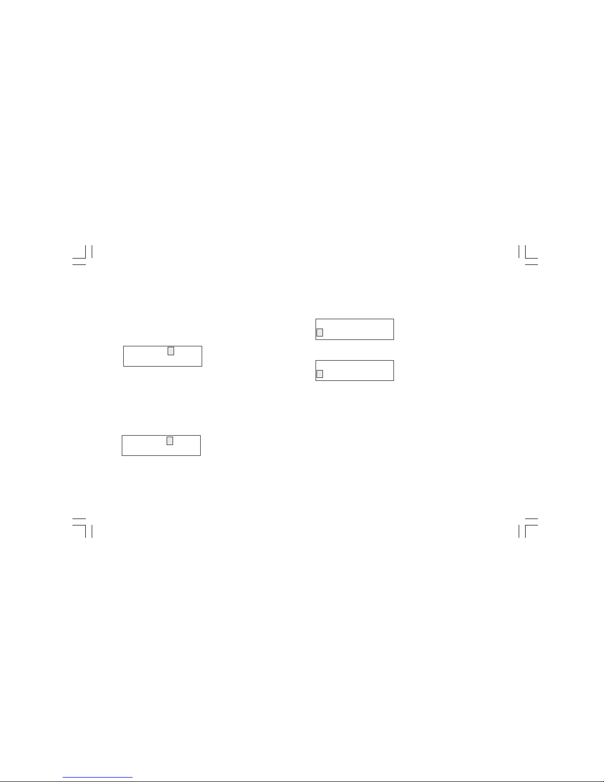
58
SECTION 4 SEQUENTIAL FUNCTION ROUTINES
a) If the selected routine does not exist, the instrument will switch
automatically to the EDIT mode.
b) If the selected routine exists, the display will show:
In this case referred to the paragraph "2- how to modify a routine".
The display will show the following:
Where :
15 shows the identification code of the selected sequence
01 is the step number you are editing.
MEASallows to insert a measurement step.
OUT allows to insert a generation step.
SBY allows to insert a "Stand-by" step.
STO allows to store, in the present step, the parameters of the
"action" inserted prior to the editing of the sequential function
routine.
NOTES:
A) When MEAS is selected, the instrument will execute the
Selection Sequence described for measurement
B) When OUT is selected, the instrument will execute the Selection
Sequence described for generation
Up to 50 program steps can be further divided in one or more routines
of different length.
4.1 - HOW TO CONSTRUCT AND STORE A NEW SEQUENTIAL
FUNCTION ROUTINE.
Push the PROG push-button; the display will show:
where:
YY indicates how many program steps are still available.
XX enter in this field the identification code number of the routine
to be created.
When it is desired to know the identification code already utilized,
depress s or t push-buttons. On the lower display line will appear
the identification code already in existence.
If the lower line is completely filled, depress s or t push-button
again to scroll the remaining codes.
NOTE: the identification codes are sorted in chronological order
and not in ascending order.
Type the desired identification code (e.g. 15) and then depress the
FUNC push-button.
PROGRAM N XX
YY FREE STEP(S)
PROGRAM N XX
1 7 5 3 12 15
PROGRAM N 15
RUN EDIT DEL
PROGRAM N 15 01
MEAS OUT SBY STO
M20-e-4.p65 7/9/01, 2:41 PM58
Page 59
59
In any of the above listed possibilities, at the end of the programming step, the display will show the programmed parameter set
followed by the step number.
Example :
NOTE: no 90 or 68 indication are shown because the instrument
will use, time by time during routine execution, the standard
actually selected.
This represents a summary of all the just programmed parameters.
Depress the FUNC push-button; the display will finally show:
Where :
TIME in minutes and seconds (max. 99' 59''), shows the time
duration of the just programmed step.
By setting 00:00 the instrument will wait for either an
operator intervention (by pressing FUNC push-button) or
logic input (RUN/WAIT) contact closure.
END VAL. This parameter is available for generation only and it
allows to program a ramp.
END VAL. is the final value to be reached in the
programmed "TIME" frame.
1) When TIME = 00:00 the END VAL. cannot be modified therefore
the program step should be necessarily a soak segment.
2) When TIME is different from 00:00, it is possible to set the END
VAL. different from the Initial Value. In this case, the program
step will be a ramp.
3) When TIME is different from 00:00, if the END VAL. is equal to
initial value, the program step is going to be a soak segment and
the TIME shows the time duration of the Soak.
NOTE: to return to the previous menu without memorizing the new
selection, depress the SCRL BACK push-button.
Depress the FUNC push-button; the instrument will switch to the
new step having stored all the parameters previously set.
Therefore, the display will show the following:
Proceed now as described for the first step.
To define the end of the sequential function routine, depress the
PROG push-button.
The instrument will memorize only the steps which have been
completed properly and return to the STAND BY mode.
NOTE: During program editing, the I/O impedance of the instru-
ment will be equal to 500 KOhm
OUT J E 25.5
150 °C 01
TIME XX:XX 01
END VAL. XXXXXX
PROGRAM N 15 02
MEAS OUT SBY STO
M20-e-4.p65 7/9/01, 2:41 PM59
Page 60
60
4.2 -HOW TO MODIFY A ROUTINE.
Depress the PROG push-button; the display will show the following:
Where:
YY indicates how many program steps are still available.
XX enter in this field the identification code number of the routine
to be created, edited or run.
When it is desired to know the identification code already utilized,
depress s or t push-buttons. On the lower display line will appear
the ID. code already in existence.
If the lower line is completely filled, depress s or t push-button
again to scroll the remaining codes.
Type the ID. code of the routine to be modified and push the FUNC
push-button.
The display will show the following:
Where:
RUN enables the sequential function routine execution;
EDIT enables the EDIT mode of the selected routine;
DEL delete the selected routine.
When it is desired to delete the selected routine, select the DEL option
and push the FUNC push-button.
The display will show the following:
Select YES and depress FUNC push-button. The instrument
deletes the selected routine and returns automatically to the
STAND BY mode.
By selecting NO the instrument returns to the previous menu.
When it is desired to modify the program, select EDIT and then
depress FUNC push-button.
The display will show the following:
The display shows the first step parameters.
Four different situations may occur:
A) The first program step is correct.
PROGRAM N XX
YY FREE STEP(S)
PROGRAM N XX
1 3 5 7 12 15
PROGRAM N 15
RUN EDIT DEL
PROG XX DELETE?
NO YES
OUT J E 25.5
150 °C 01
M20-e-4.p65 7/9/01, 2:41 PM60
Page 61
61
Push the FUNC push-button; the display will show the following:
If no modifications are required, push the FUNC push-button
again, the instrument goes to the next step.
B) It is desired to delete the selected program step.
Push the DEL/WAIT push-button. The instrument deletes all the
data related with the selected step and renumbers the remaining steps.
C) It is desired to modify one (or more) data of this step. Push the
REV/MOD push-button.
The instrument start the selection sequence.
Insert all the parameters of this step.
NOTE: during routine editing, the instrument does not limit the
TC or RTD selection in accordance with the actual standard
selected (IPTS-68 or ITS 90) because it will use, time by time
during routine execution, the selected standard.
D) It is desired to insert a new program step between step (a) and
step (b).
Pushing the FUNC push-button and reach the program step (b).
Push the Set up/ Ins push-button.
The instrument renumbers the following steps and start the
selection sequence.
NOTES:
1) To scroll back the selection sequence use the SCRL BACK pushbutton.
2) To end the EDIT mode of the sequential function routine,
depress the PROG push-button. The instrument will memorize
only the steps which have been properly completed and will
return to the STAND BY mode.
4.3 - HOW TO RUN A ROUTINE.
Depress the PROG push-button; the display will show the following:
Type the desired program number (e.g. 18) and depress the FUNC
push-button.
The display will show the following:
Select RUN and push FUNC.
The display will show:
Where XX is the number of routine repetitions.
NOTE: Setting a value equal to 00, the instrument repeats continu-
TIME XX:XX 01
END VAL. XXXXX
PROGRAM N XX
YY FREE STEP(S)
PROGRAM N 18
REPETITIONS N XX
PROGRAM N 18
RUN EDIT DEL
M20-e-4.p65 7/9/01, 2:41 PM61
Page 62

62
ously the selected routine (it is possible to stop the routine
repetition pushing the ON/OFF push-button or the STAND
BY push-button for more than 1.5 sec).
Type the desired repetition number and push FUNC push-button.
The display will show the data of the executing step.
As an example:
Where:
01 indicates the number of the step in execution.
XX indicates the number of repetition to be execute.
: flashing means that the program is in execution
NOTE: During routine execution a conflict may occur when the
selected standard is equal to ITS-90 and the selected routine
accomodates one or more steps with an RTD Ni100 or a TC
type L or U linearization.
In these cases, when the program execution reaches a
conflicting steps, the instrument will show the ERROR 5
indication.
To delete this error, depres the DEL/WAIT pushbuton, the
instrument will use, only for this step, the IPTS-68 standard and
it will continue the routine execution.
When the instrument is running a program it is possible:
1) To go to the next step by pushing the FUNC push-button.
2) To come back to the previous step by pushing SCRL BACK
push-button.
3) To stop temporarily the routine execution by depressing the
DEL/WAIT push-button or by RUN/WAIT digital input contact
closure.
In WAIT mode the instrument stops time count and continues to
perform the last operative function.
The step indication is flashing.
When the WAIT condition is enabled during a ramp generation,
the instrument will maintain the output value actually generated.
NOTE: during WAIT mode the FUNC and SCRL BACK pushbuttons maintain their functionality; in other words, they produce
respectively a dump to the next or previous step of the routine
but also the new step will be in WAIT condition.
To continue routine execution, push the DEL/WAIT push-button
again.
To abort the routine execution, it is possible:
1) to keep down the STAND BY push-button for more than 1.5
seconds and go to the STAND BY mode.
2) to push twice the ON/OFF push-button.
At the end of routine execution, the instrument goes automatically
to the STAND BY mode.
OUT J E 25.5
150 °C 01:XX
M20-e-4.p65 7/9/01, 2:41 PM62
Page 63
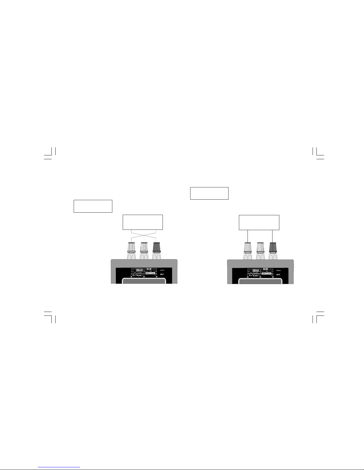
63
During OHM simulation, a measuring current lower than 100 mA
or higher than 2 mA can produce the following indication
SECTION 5 ERROR MESSAGES
5.1 LOAD ERRORS
During OHM simulation, a reverse measuring current causes the
"MISCON" indication on the display.
Revert the measuring wires.
OUT Ohm
MISCON W
-
OHM meter
OUT Ohm
------ W
+
-
OHM meter
+
M20-e-5.p65 7/9/01, 2:42 PM63
Page 64

64
During TC and RTD measurement, if, during configuration
procedure the open input test has been selected and the instrument
detects an open circuit condition, it will show the following indication:
During mV, TC or mA generation, when an overload higher than
1% of the nominal value is detected, the instrument will show:
NOTE: the instrument shows in the xx fields the selected engineering unit.
5.2 ERROR MESSAGES
The instrument performs, at instrument power up and during normal
operativity, diagnostic controls.
Two type of errors may occur:
Not fatal errors (code 1, 2, 3, 4 or 5)
When a not fatal error is detected the instrument shows, on the
lower row of the display, the "ERROR X !" messages where X is
the error code.
If a not fatal error is detected it is possible to ignore the error
indication by pushing the DEL pushbutton but the accuracy of the
instrument is not assured.
Fatal errors (code 6, 7 and 8)
When a fatal error is detected the instrument shows, on the lower
row of the display, the "FATAL ERROR X !" messages where X
is the error code.
If a fatal error is detected, switch OFF the instrument and then
switch ON again.
In both cases, if the error persist send back the instrument to your
supplier.
5.3 ERROR LIST
Not fatal erorrs
1 one of the configuration parameters is out of range
2 One of the zero calibration parameters is out of range
3 One of the initial or full scale calibration parameters is out
of range
4 General error during calibration
5 Conflict between the selected temperature standard and
sensor linearization.
Fatal errors
6 Write EEPROM error
7 Program path violation
8 Self test failure
OUT xx
------ xx
MEAS K I 25.0
OPEN °C
M20-e-5.p65 7/9/01, 2:42 PM64
Page 65
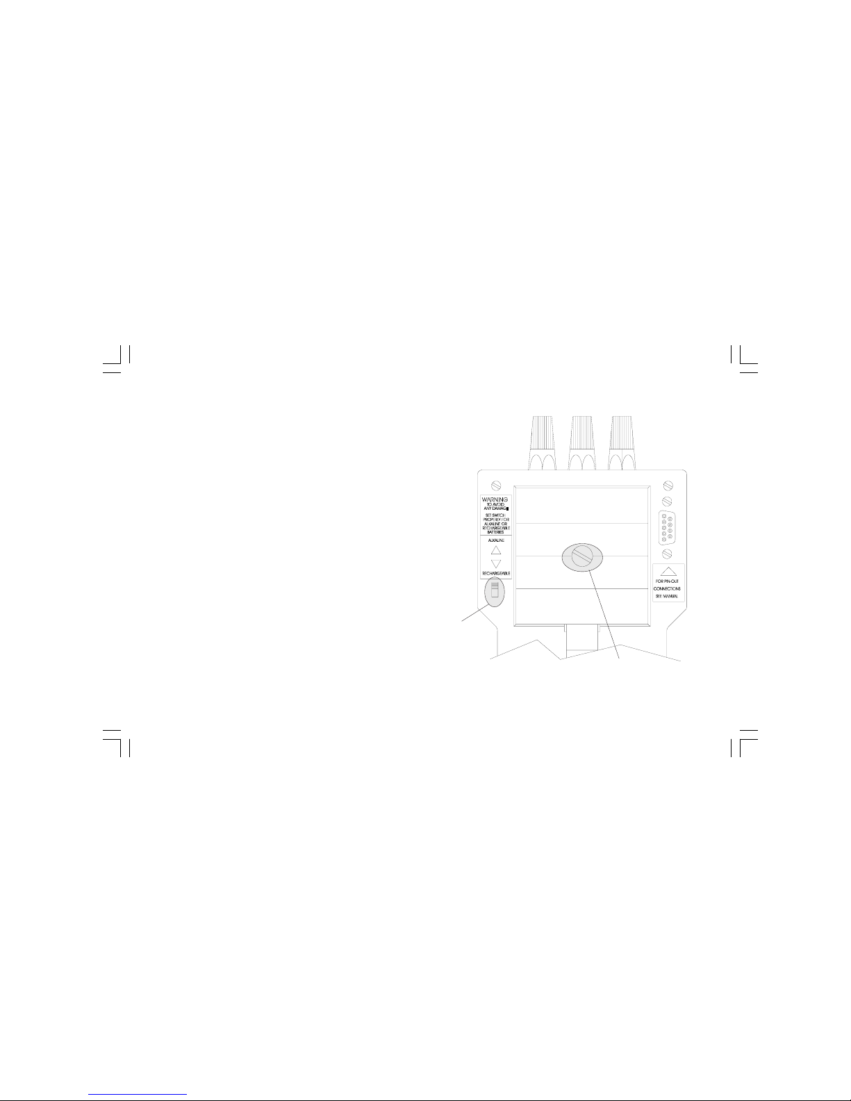
65
SECTION 6 MAINTENANCE
6.1 POWER SUPPLY
For instrument power supply it is possible to use 4 battery AA size
and/or the standard AC adapter.
Batteries can be rechargeable or non rechargeable types.
The rechargeable type can be:
- Ni/Cd (standard) 1,2 V cell with a capacity of 850 mA/h
- Ni/MH 1,2 V cell with a capacity of 1200 mA/h.
The non rechargeable type can be only ALKALINE 1,5 V cell.
The AC adapter has an output equal to 7,5 V with a maximum
current equal to 1,2 A.
The AC adapter is capable to supply the instrument and, simultaneously, to recharge the batteries.
WARNING:
1) Before to connect the AC adapter to the instrument, set the
battery type selector (see fig. 1) in accordance with the battery
type inserted in the instrument.
2) Don't mix old batteries with new ones.
3) Don't use mixed battery types.
Fig. 1
battery
type
selector
screw for the
acces to the
battery pack
M20-e-6.p65 7/9/01, 2:43 PM65
Page 66
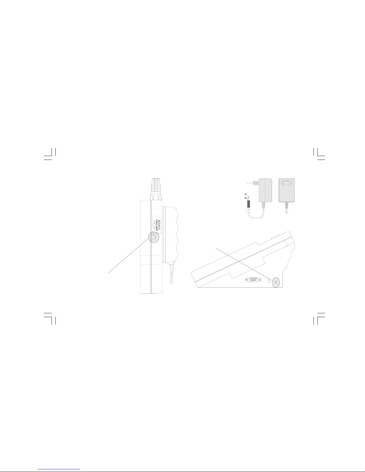
66
6.2 BATTERY RECHARGE
This instrument is equipped with an AC
adapter (see fig. 3) usable to recharge
the batteries.
When the AC adapter is connected
directly to the instrument (see fig. 2)
and the battery type selector (see fig. 1)
is set for rechargeable battery type, the
batteries will be recharged in trickle
charge mode.
Battery charge can be made with the
instrument switched ON or OFF.
The trickle charge current is about 50
mA.
In trickle charge mode, a complete
recharge can require up to:
- 12 hours for Ni/Cd cells;
- 20 hours for Ni/MH cells.
The optional Desk-top-stand
(see fig. 4) can provide a quick
recharge mode.
The quick recharge current is
equal to 250 mA.
In quick charge mode, a
complete recharge can require
up to:
- 3 hours for Ni/Cd cells;
- 5 hours for Ni/MH cells.
NOTE: it is not advisable to make a frequent use of the quick
charge mode (see chapter "Battery maintenance").
Fig. 4
Fig. 2
AC adapter
direct connection
Fig. 3
AC adapter connection through
desk-top-stand
M20-e-6.p65 7/9/01, 2:43 PM66
Page 67

67
6.3 BATTERY MAINTENANCE
The battery recharging system is optimized for the best battery life
expectancy.
Any way, every 2 or 3 months it is suggested to discharge completely the battery pack leaving ON the instrument while it switch
OFF automatically. Than recharge deeply for 24 hours with the AC
adapter connected directly to the instrument.
6.4 BATTERY REPLACEMENT
When it is necessary to replace the battery pack, proceed as
follows:
1) unscrew the battery cover (see fig. 1)
2) remove the battery cover
3) pull out the old batteries
4) insert the new batteries paying attention to the polarity.
5) set the battery type selector in accordance with the type of
batteries inserted in the instrument.
6) reposition the battery cover
7) screw the battery cover.
WARNING:
1) After a battery replacement, set the battery type selector (see
fig. 1) in accordance with the battery type inserted in the
instrument.
2) Don't mix old batteries with new ones.
3) Don't use mixed battery types.
6.5 HOW TO CLEAN THE INSTRUMENT
To clean plastic, rubber, and external parts use only Alcohol:
- Ethyl (pure or denatured) [C2H5OH]
- Isopropil (pure or denatured) [(CH3)2CHOH]
6.6 INTERNAL FUSES
The instrument is protected by 2 pico fuses rated 1A, 125 V, quick
acting (F) type.
The first one protects the power supply circuits.
The second one protects the input circuits.
WARNING: the fuse replacement can be made ONLY BY QUALIFIED PERSONNEL. IF ANY PROBLEM IS DETECTED, SEND
THE INSTRUMENT TO LOCAL ERO ELECTRONIC BRANCH
OFFICE OR REPRESENTATIVE.
6.7 INSTRUMENT MAINTENANCE
Every year it is advisable to verify the instrument accuracy.
This control must be made by a specialized metrology laboratory or
directly by ERO factory in Novara.
M20-e-6.p65 7/9/01, 2:43 PM67
Page 68

Ero Electronic s.r.l.
Via E. Mattei, 21
28100 Novara
Italy
Tel. (+39) 0321-481111
Fax. (+39) 0321-481112
An Invensys Company
M20-e-6.p65 7/9/01, 2:43 PM68
 Loading...