

Page 1
LFS - ServoLFS - Servo
LFS - ServoLFS - Servo
LFS - Servo
170.IU0.LFS.SB0 09/05
UU
UU
U
USER MANUAL USER MANUAL
USER MANUAL USER MANUAL
USER MANUAL
UU
UU
U
ISTRUZIONI D'USO ISTRUZIONI D'USO
ISTRUZIONI D'USO ISTRUZIONI D'USO
ISTRUZIONI D'USO
Nuovo-3 15/09/2005, 9.391
Page 2

INDEX
MOUNTING REQUIREMENTS........................... 1
OUTLINE AND CUT OUT DIMENSIONS ........... 2
CONNECTION DIAGRAMS ................................ 3
PRELIMINARY HARDWARE SETTINGS ........... 9
CONFIGURATION PROCEDURE ....................10
OPERATIVE MODE.......................................... 19
Display function.......................................... 19
Indicators ................................................... 19
Pushbutton function during operating mode 20
Feedback potentiometer calibration ........... 20
Enable/disable the control output ...............21
Manual function.......................................... 21
Direct access to the set point ..................... 22
Operative set point selection ...................... 22
Lamp test ...................................................22
Serial link ................................................... 23
SMART function......................................... 23
OPERATIVE PARAMETERS ............................ 24
ERROR MESSAGES ........................................ 27
GENERAL INFORMATION ............................... 30
MAINTENANCE ................................................ 34
DEFAULT PARAMETERS ............................... A.1
GB
INDICE
MONTAGGIO...................................................... 1
DIMENSIONI E FORATURA............................... 2
COLLEGAMENTI ELETTRICI............................. 3
IMPOSTAZIONI HARDWARE PRELIMINARI .... 9
PROCEDURE DI CONFIGURAZIONE .............10
MODO OPERATIVO ......................................... 19
Funzionalità del visualizzatore ................... 19
Indicatori .................................................... 19
Operatività dei tasti durante
il modo operativo........................................ 20
Calibrazione del potenziometro
di controreazione ....................................... 20
Abilitazione/disabilitazione
dell'uscita regolante ................................... 21
Funzionamento in modo MANUALE .......... 21
Modifica diretta del set point ...................... 22
Selezione del set point operativo ............... 22
Lamp test ...................................................22
Interfaccia seriale ....................................... 23
Funzione SMART ...................................... 23
PARAMETRI OPERATIVI ................................. 24
MESSAGGI DI ERRORE .................................. 27
DATI TECNICI .................................................. 30
MANUTENZIONE ............................................. 34
DEFAULT PARAMETERS ............................... A.1
I
LFS-servo-0-00.p65 1/14/02, 3:41 PM2
Page 3

LFS-servo-0-00.p65 1/14/02, 3:41 PM3
Page 4
1
GB
MOUNTING REQUIREMENTS
Select a mounting location where there is
minimum vibration and the ambient temperature
range between 0 and 50 °C.
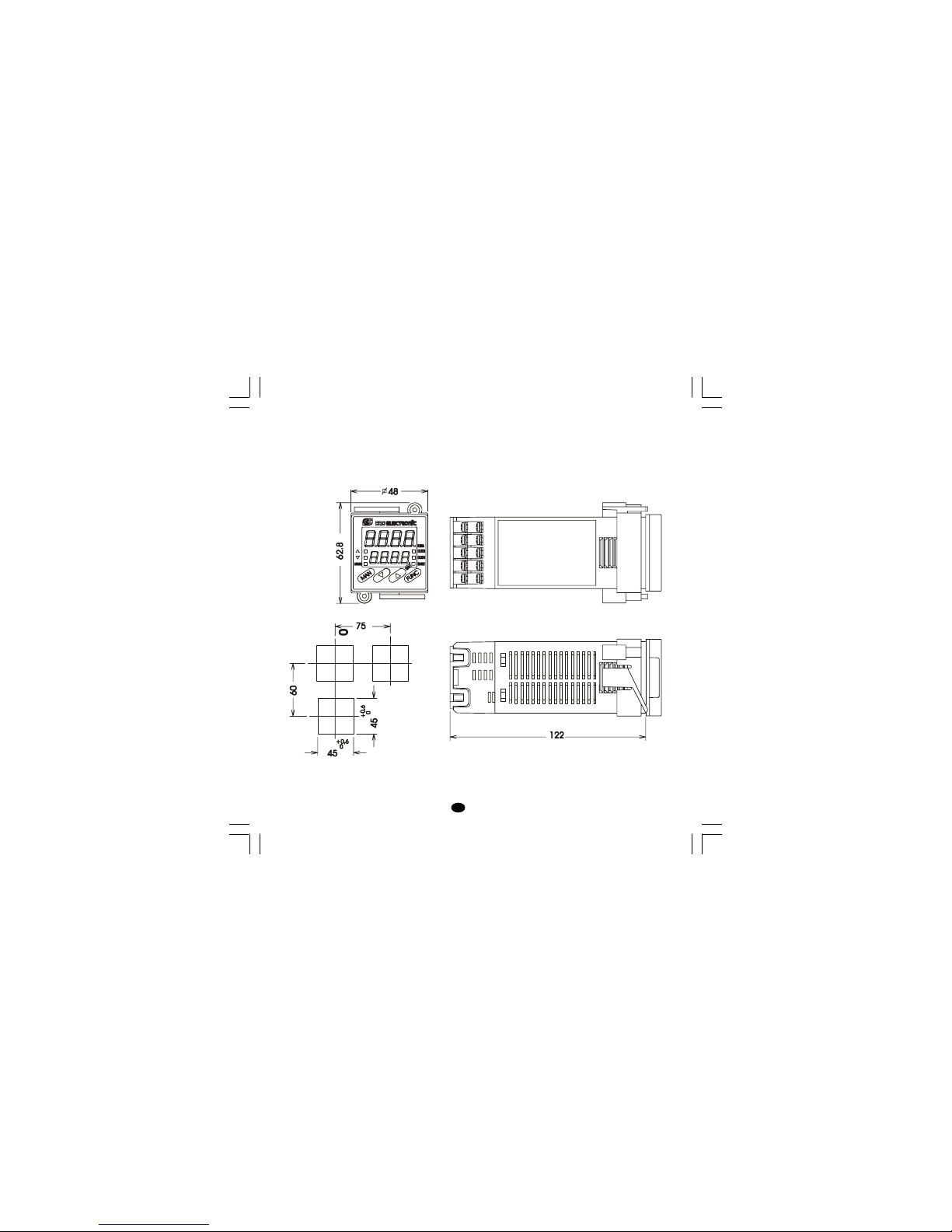
The instrument can be mounted on a panel up to
15 mm thick with a square cutout of 45 x 45 mm.
For outline and cutout dimensions refer to Fig. 2.
The surface texture of the panel must be better
than 6,3 µm.
The instrument is shipped with rubber panel
gasket (50 to 60 Sh).
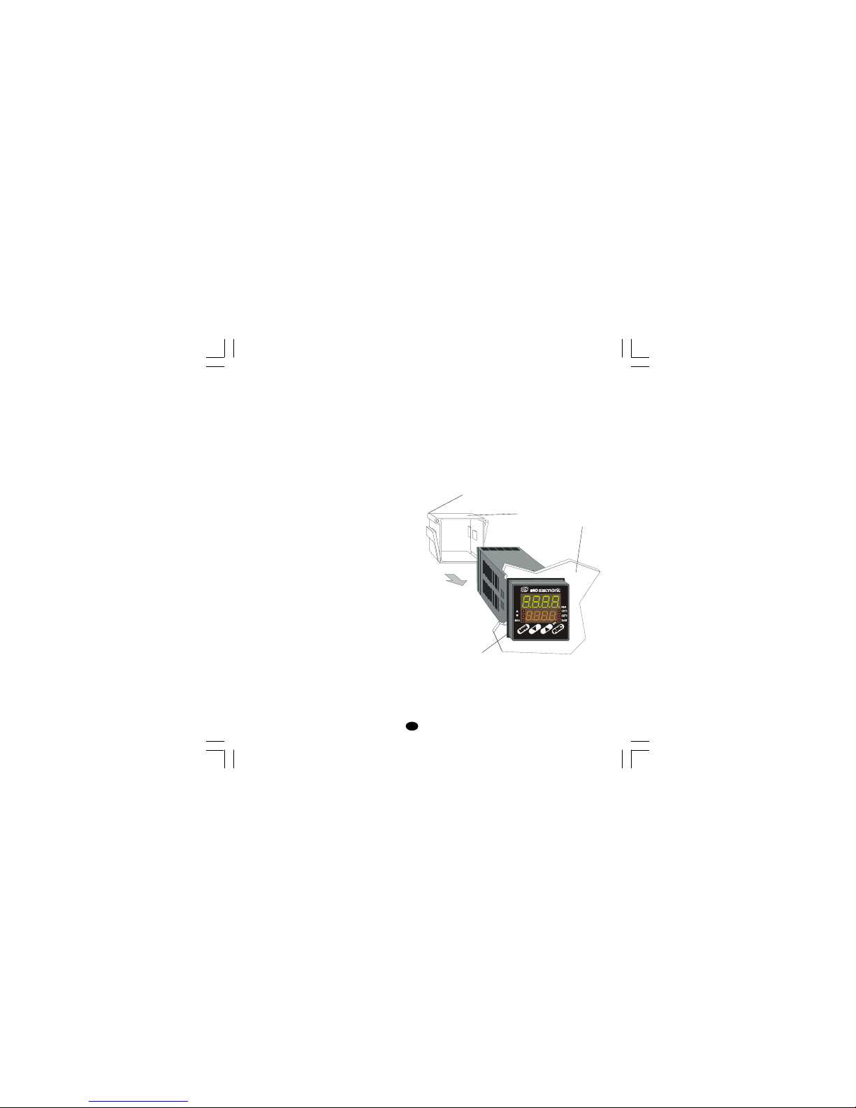
To assure the IP65 and NEMA 4 protection, insert
the panel gasket between the instrument and the
panel as shown in fig. 1.
While holding the instrument against the panel
proceed as follows:
1) insert the gasket in the instrument case;
2) insert the instrument in the panel cutout;
3) pushing the instrument against the panel, insert
the mounting bracket;
4) with a screwdriver, turn the screws with a
torque between 0.3 and 0.4 Nm.
Screw
Fig. 1
bracket
Panel
Gasket
LFS-servo-1-02.p65 1/14/02, 3:43 PM1
Page 5
2
GB
OUTLINE AND CUT OUT
DIMENSIONS
Fig. 2
LFS-servo-1-02.p65 1/14/02, 3:43 PM2
Page 6
3
GB
CONNECTION DIAGRAMS
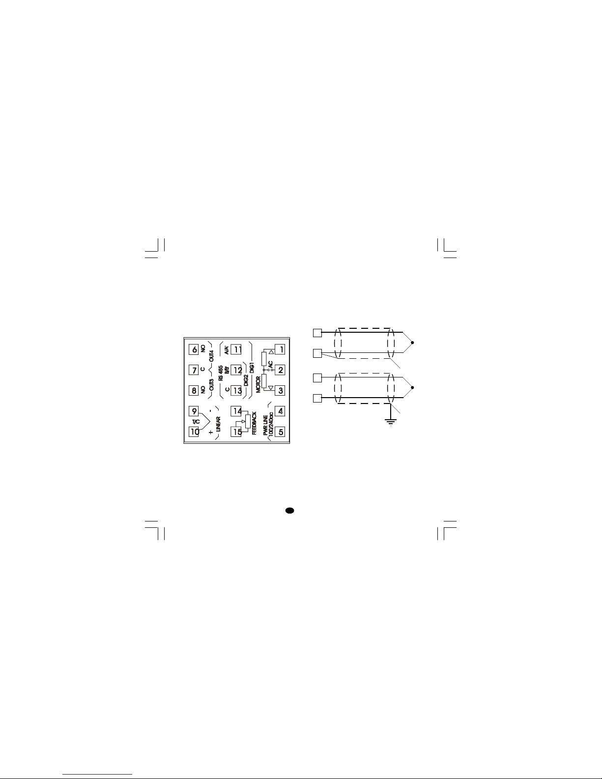
Connections are to be made with the instrument
housing installed in its proper location.
Fig. 3 REAR TERMINAL BLOCK
A) MEASURING INPUT
NOTE: Any external components (like zener
barriers etc.) connected between sensor and input
terminals may cause errors in measurement due
to excessive and/or not balanced line resistance or
possible leakage currents.
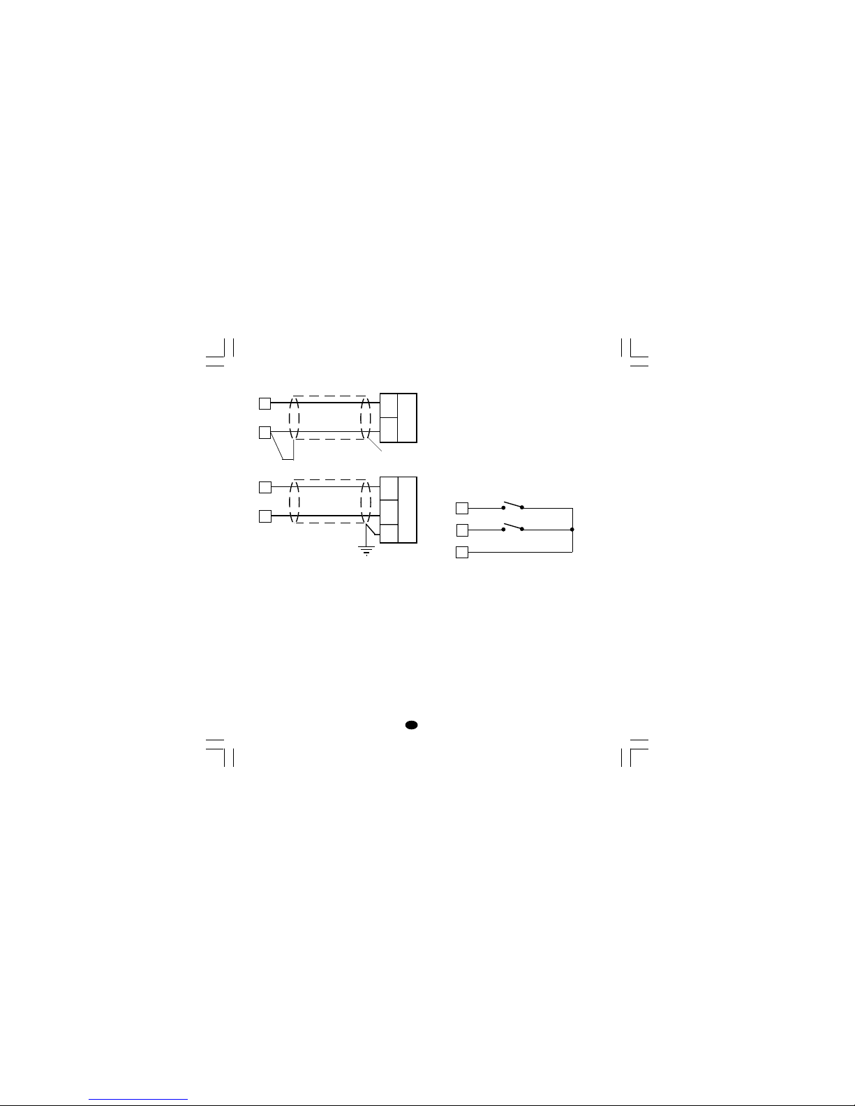
TC INPUT
Fig. 4 THERMOCOUPLE INPUT WIRING
NOTE:
1) Don’t run input wires together with power
cables.
2) For TC wiring use proper compensating cable
preferable shielded.
3) when a shielded cable is used, it should be
connected at one point only.
Shield
Shield
10
9
+
_
10
9
+
_
LFS-servo-1-02.p65 1/14/02, 3:43 PM3
Page 7
4
GB
LINEAR INPUT
Fig. 5 mA, mV AND V INPUTS WIRING
NOTE:
1) Don’t run input wires together with power
cables.
2) Pay attention to the line resistance; a high line
resistance may cause measurement errors.
3) When shielded cable is used, it should be
grounded at one side only to avoid ground loop
currents.
4) The input impedance is equal to:
< 5 Ω for 20 mA input
> 1 MΩ for 60 mV input
> 400 kΩ for 5 V input
> 400 kΩ for 10 V input
LOGIC INPUT
Safety note:
1) The "serial comunication" and the "logic input"
options are mutually exclusive.
2) Do not run logic input wiring together with
power cables.
3) Use an external dry contact capable of
switching 0.5 mA, 5 V DC.
4) The instrument needs 100 ms to recognize a
contact status variation.
5) The logic inputs are isolated by the measuring
input
Fig. 7 - LOGIC INPUT WIRING
This instrument is provided with 2 logic inputs.
The logic input 1 allows to select the operative set
point as follows
logic input 1 op. set point
open SP
close SP2
The logic input 2 allows to select the AUTO /
MANUAL operative mode (see also P24
parameter):
logic input 2 operat. mode
open AUTO
close MANUAL
Shield
_
+
mA,
mV
or
V
9
+
_
G
mA
mV
or
V
10
9
10
11
Log. input 1
12
13
Log. input 2
LFS-servo-1-02.p65 1/14/02, 3:43 PM4
Page 8
5
GB
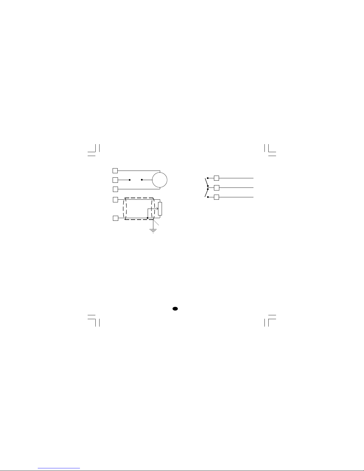
VALVE MOTOR DRIVE OUTPUT.
Fig. 8 - SERVOMOTOR WIRING
The two relay outputs are interlocked.
NOTE:
1) Before connecting the instrument to the power
line, make sure that line voltage and the load
current are in accordance with the contact rating
(3A/250V AC on resistive load).
2) To avoid electric shock, connect power line at the
end of the wiring procedure.
3) For servomotor connections use No 16 AWG or
larger wires rated for at last 75 °C.
4) Use copper conductors only.
5) Don’t run input wires together with power cables.
6) For feedback potentiometer, use shielded cable
with the shield connected to the earth at one point
only.
7) The relay outputs are protected by varistor
against inductive load with inductive component up to 0.5 A.
1
2
3
Servo-
motor
Power
line
s (Open the valve)
t (Close the valve)
RELAY OUTPUTS
Fig. 9 RELAY OUTPUTS WIRING
NOTE: OUT 1 can be used either as servomotor
output or as time proportional relay output;
by the P5 parameter (see pag.11) it is
possible to set the desired output.
All relay outputs are protected by varistor against
inductive load with inductive component up to 0.5 A.
The contact rating of the OUT 3 and 4 is 2A/250V AC
resistive load.
The number of operations is 1 x 10
5
at specified
rating.
Alarm 2 and alarm 3 are in OR condition on the
out 4.
The following recommendations avoid serious
problems which may occur, when using relay
output for driving inductive loads.
8
6
7
C - OUT 3/4
NO - OUT 4
NO - OUT 3
OUT 4
OUT 3
14
15
Feedback
potentiometer
Shield
LFS-servo-1-02.p65 1/14/02, 3:43 PM5
Page 9
6
GB
INDUCTIVE LOADS
High voltage transients may occur when switching
inductive loads.
Through the internal contacts these transients may
introduce disturbances which can affect the
performance of the instrument.
The internal protection (varistor) assures a correct
protection up to 0.5 A of inductive component.
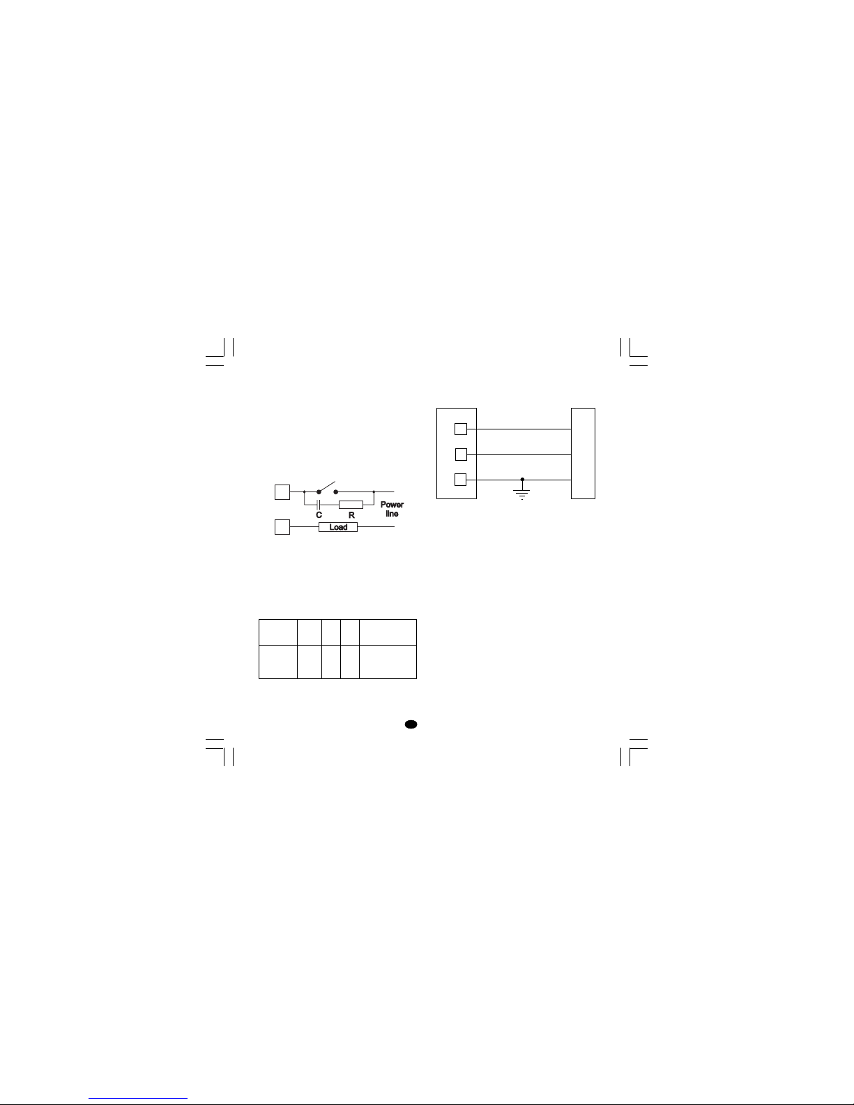
The same problem may occur when a switch is
used in series with the internal contacts as shown
in Fig. 10.
Fig. 10 EXTERNAL SWITCH IN SERIES WITH
THE INTERNAL CONTACT
In this case it is recommended to install an
additional RC network across the external contact
as shown in Fig. 10
The value of capacitor (C) and resistor (R) are
shown in the following table.
Anyway the cable involved in relay output wiring
must be as far away as possible from input or
communication cables.
SERIAL INTERFACE
RS-485 interface allows to connect up to 30
devices with one remote master unit.
Fig. 11 - RS-485 WIRING
The cable length must not exceed 1.5 km at 9600
BAUD.
The "serial comunication" and the "logic input"
options are mutually exclusive.
NOTE: The following report describes the signal
sense of the voltage appearing across the
interconnection cable as defined by EIA for
RS-485.
a) The ” A ” terminal of the generator shall be
negative with respect to the ” B ” terminal for
a binary 1 (MARK or OFF) state.
b) The ” A ” terminal of the generator shall be
positive with respect to the ” B ” terminal for
a binary 0 (SPACE or ON)
12
13
COMMON
11
B'/B
B/B'
A/A'
A'/A
M
A
S
T
E
R
I
N
S
T
R
U
M
E
N
T
LOAD
(mA)
<40 mA
<150 mA
<0.5 A
C
(µF)
0.047
0.1
0.33
R
(Ω)
100
22
47
P.
(W)
1/2
2
2
OPERATING
VOLTAGE
260 V AC
260 V AC
260 V AC
LFS-servo-1-02.p65 1/14/02, 3:43 PM6
Page 10

7
GB
POWER LINE WIRING
Fig. 12 POWER LINE WIRING
NOTE:
1) Before connecting the instrument to the power
line, make sure that line voltage corresponds to
the descrtiption on the identification label.
2) To avoid electric shock, connect power line at the
end of the wiring procedure.
3) For supply connections use No 16 AWG or larger
wires rated for at last 75 °C.
4) Use copper conductors only.
5) Don't run input wires together with power cables.
6) For 24 V DC the polarity is a do not care condition.
7) The power supply input is fuse protected by a sub
miniature fuse rated T, 1A, 250 V.
When fuse is damaged, it is advisable to verify the
power supply circuit, so that it is necessary to
send back the instrument to your supplier.
8) The safety requirements for Permanently Connected Equipment say:
- a switch or circuit-breaker shall be included in the
building installation;
- It shall be in close proximity to the equipment and
within easy reach of the operator;
- it shall be marked as the disconnecting device for
the equipment.
NOTE: a single switch or circuit-breaker can drive
more than one instrument.
9) When a neutral line is present, connect it to
terminal 5.
R (S,T)
R (S,T)
N
N
POWER LINE 100 V to 240 V A.C
(50/60Hz)
4
5
LFS-servo-1-02.p65 1/14/02, 3:43 PM7
Page 11
8
GB
PRELIMINARY HARDWARE
SETTINGS
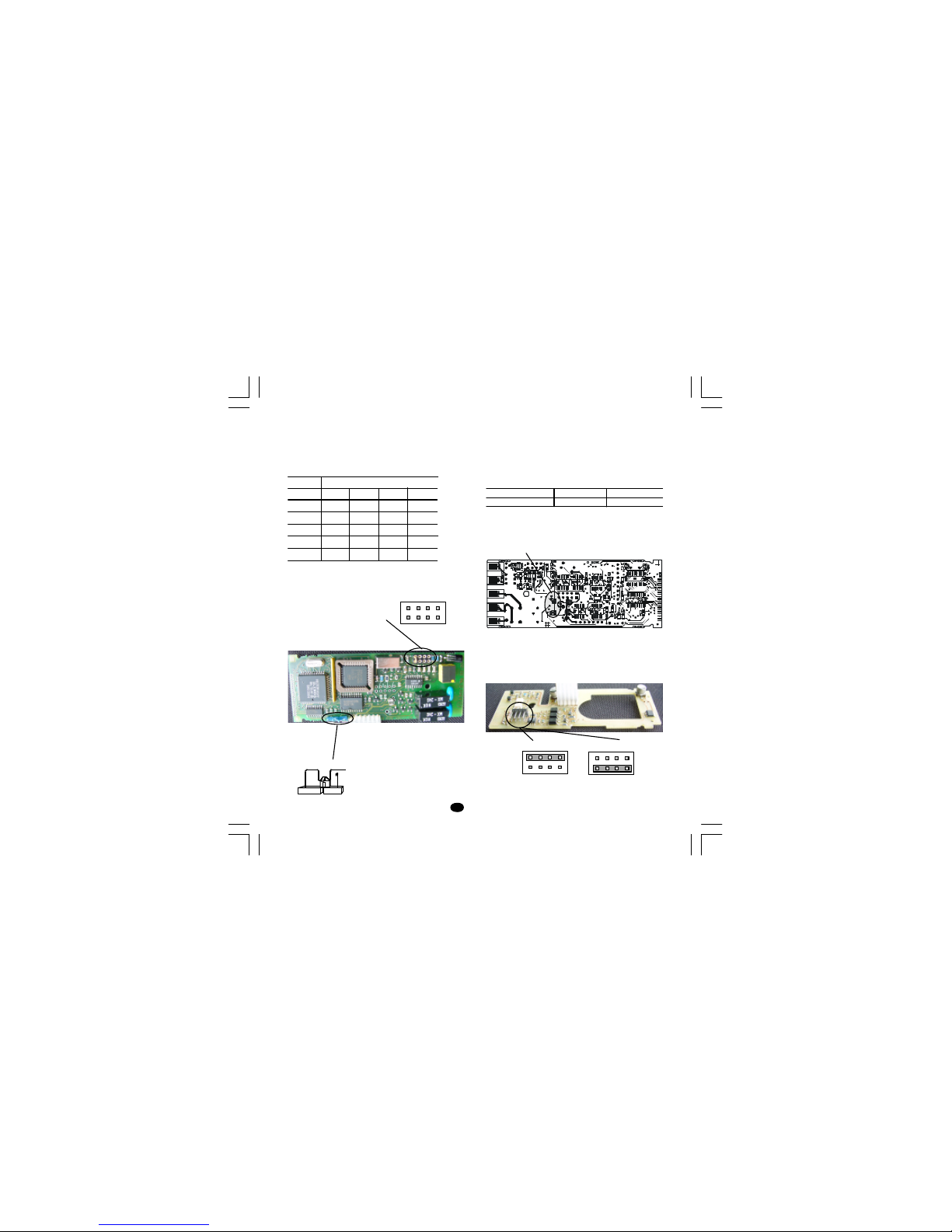
1) Remove the instrument from its case.
2) It is necessary to set J1 according to the desired
input type as shown in the following figure.
INPUT J1
TYPE 1-2 3-4 5-6 7-8
TC close open open open
60 mV close open open open
5 V open close open open
10 V open open close open
20 mA open open open close
OPEN INPUT CIRCUIT
This instrument is able to identify the open circuit
for TC input.
For TC input, it is possible to select overrange
indication (standard) or underrange indication setting the CH1 and SH1 according to the following
table:
Overrange (STD) CH1 = close SH1 = open
Underrange CH1 = open SH1 = close
Both pads are located on the soldering side of the
CPU card
Logic input - serial interface selection
When both options are fitted, select the desired
function by setting J105 as follows:
Fig.15Fig. 13
Fig. 14
Fig. 13
SH1 CH1
SW1
1 3 5 7
2 4 6 8
J1
J105
Logic inputs
1 3 5 7
2 4 6 8
1 3 5 7
2 4 6 8
RS-485
Nuovo-1 15/09/2005, 9.458
Page 12

9
GB
INSTRUMENT CONFIGURATION
1) Switch on the instrument.
The upper display shows the measured value
while the lower display shows the programmed
set point value (we define the above condition as
“normal display mode”).
2) Push "FUNC" pushbutton and, maintaining the
pressure, push the "MAN" pushbutton for more
than 4 seconds.
The lower display will show
ConF while the
upper display will show
C.mOn.
NOTE: two different configuration mode are
possible:
A) Monitor mode: in this mode it is possible to
monitor but not to modify the configuration
parameter. During the monitor mode the
instrument continue to perform the standard
control.
B) Modify mode: in this mode it is possible to
verify and to modify all configuration
parameter.
3) By s and t pushbuttons select the
C.mOd
indication (modify mode).
4) Push the "FUNC" pushbutton.
NOTES:
1) When modify mode is started, the instrument
stops the control action and:
- sets control outputs to OFF;
- sets alarms in no alarm condition;
- disables the serial link.
2) If the configuration parameters are protected by
security code the display will show:
By s and t keys enter a value equal to the
configuration security code (see P51 parameter) or the master key code (see appendix A).
Note: the master key code allows to enter in
modify configuration parameters mode either if
the configuration security code is lost or if the
configuration parameters are always protected
(P51 = 1).
When it is desired to exit from configuration modify
mode proceed as follows:
a) Push "FUNC" or "MAN" push-button more times
until the
C.End parameter is displayed.
b) Pushing ”s” or “t” push-button select the
yes indication.
c) Push “FUNC” push-button. The instrument ends
the configuration modify mode, preforms an
automatic reset and restarts in the run time
mode.
Pushbutton function during configuration
mode
FUNC = This will memorize the new value of the
selected parameter and go to the next
parameter (increasing order).
MAN = This will scroll back the parameters
without memorization of the new value.
s = This will increase the value of the
selected parameter
t = This will decrease the value of the
selected parameter.
LFS-servo-1-02.p65 1/14/02, 3:43 PM9
Page 13

10
GB
CONFIGURATION PARAMETERS
Notes:
1) In the following pages we will describe all the
parameters of the instrument but the instrument
will show only the parameters related with the
specific hardware and in accordance with the
specific instrument configuration (i.e. setting
Ser1 = OFF (not used), all the parameters
related with serial interface will not be
displayed).
2) During configuration mode, the lower display
shows the mnemonic code of the selected
parameter while the upper display shows the
value or the status assigned to the selected
parameter.
dF.CndF.Cn
dF.CndF.Cn
dF.Cn - Load default configuration data
This parameter is skipped in monitor configuration
parameter mode.
OFF = No default data loading
tb.1 = Load default data from European table
(TB1)
tb.2 = Load default data from American table
(TB2)
SEr1SEr1
SEr1SEr1
SEr1 = Serial interface protocol
OFF = No serial interface
ero = Polling/selecting ERO
nbUs = Modbus
jbUs = Jbus
NOTE: the "serial comunication" and the "logic
input" options are mutually exclusive and
selectable by a jumper setting.
ser2ser2
ser2ser2
ser2 = Serial link device address
Not available when SEr1 = OFF
From 1 to 95 for ERO protocol
From 1 to 255 for all the other protocols
NOTE: the electrical characteristic of the RS 485
serial interface will allow the connection of 31
devices maximum.
ser3ser3
ser3ser3
ser3 = Baude rate for serial link
Not available when SEr1 = OFF
From 600 to 19200 baud.
NOTE: 19200 baud is shown on display as 19.2.
ser4ser4
ser4ser4
ser4 = Byte format for serial link
Not available when SEr1 = OFF
7e = 7 bits + even parity (For ERO protocol only)
7O = 7 bits + odd parity (For ERO protocol only)
8E = 8 bits + even parity
8O = 8 bits + odd parity
8 = 8 bits without parity
P1 - Input type and standard range
0 = TC type L range 0 / +400.0 °C
1 = TC type L range 0 / +900 °C
2 = TC type J range-100.0 / +400.0 °C
3 = TC type J range -100 / +1000 °C
4 = TC type K range-100.0 / +400.0 °C
5 = TC type K range -100 / +1370 °C
6 = TC type T range -199.9 / +400.0 °C
7 = TC type N range -100 / +1400 °C
8 = TC type R range 0 / +1760 °C
9 = TC type S range 0 / +1760 °C
10 = TC type B range 0 / +1820 °C
13 = mV Linear range 0 / 60 mV
14 = mV Linear range 12 / 60 mV
15 = mA Linear range 0 / 20 mA
16 = mA Linear range 4 / 20 mA
17 = V Linear range 0 / 5 V
18 = V Linear range 1 / 5 V
19 = V Linear range 0 / 10 V
20 = V Linear range 2 / 10 V
LFS-servo-1-02.p65 1/14/02, 3:43 PM10
Page 14

11
GB
21 = TC type L range 0 / +1650 °F
22 = TC type J range -150 / +1830 °F
23 = TC type K range -150 / +2500 °F
24 = TC type T range -330 / +750 °F
25 = TC type N range -150 / +2550 °F
26 = TC type R range 0 / +3200 °F
27 = TC type S range 0 / +3200 °F
28 = TC type B range 0 / + 3310 °F
NOTE: selecting P1 = 0, 2, 4, 6, 10 or 28, the
instrument set automatically P43 = filt. For all
the remaining ranges it will set P43 = nOfl.
P2 = Decimal point position
This parameter is available only when a linear
input is selected (P1 = 13 to 20).
----. = No decimal figure.
---.- = One decimal figure.
--.-- = Two decimal figures.
-.--- = Three decimal figures.
P3 = Initial scale value
For linear inputs, it is programmable from -1999 to
4000 and P3 value may be greater than P4
value in order to obtain a reverse read-out.
For TC inputs, it is programmable within the input
range.
When this parameter is modified, rL parameter will
be re-alligned to it.
P4 = Full scale value
For linear inputs, it is programmable from -1999 to
4000.
For TC inputs, it is programmable within the input
range.
When this parameter is modified, rH parameter will
be re-alligned to it.
The initial and full scale values determine the input
span which is used by the PID algorithm, the
SMART and the alarm functions.
NOTE: the minimum input span (S = P4 - P3), in
absolute value, should be set as follows:
- For linear inputs, S
> 100 units.
- For TC input with °C readout, S
> 300 °C.
- For TC input with °F readout, S
> 550 °F.
P5 = Output 1 type
sm.Ol = servomotor open loop.
sm.Cl = servomotor close loop.
rEU = time proportional control output with reverse
action
dir = time proportional control output with direct
action.
NOTES:
1) If P5 is changed to "sm.Ol " or it is changed from
"sm.Ol " to another selection, the parameter P41
will be forced to 0.
2) If P5 is changed to "rEU" the cycle time (Cy1) will
be forced to 15 s
3) If P5 is changed to "dir" the cycle time (Cy1)
will be forced to: 10 s when P25 = Air
4 s when P25 = OIL
2 s when P25 = H2O
t
INPUT
t
OUTPUT
t
INPUT
t
OUTPUT
Reverse Direct
LFS-servo-1-02.p65 1/14/02, 3:44 PM11
Page 15

12
GB
P6 = Valve position indication.
This parameter is available only if P5 = sm.Ol.
fb = the valve position will be displayed
no.fb = the valve position will not be displayed (the
feedback potentiometer can be omitted)
P7 = Output 3 function.
none = output not used.
al1.p = it is used as Alarm 1 output and the
alarm 1 is programmed as process
alarm.
al1b = it is used as Alarm 1 output and the
alarm 1 is programmed as band alarm.
al1.d = it is used as Alarm 1 output and the alarm
1 is programmed as deviation alarm.
rEU = it is used as second time proportional
control output with reverse action.
dir = it is used as second time proportional
control output with direct action.
NOTES:
1) If P7 is changed to "rEU" the cycle time (Cy3) will
be forced to 15 s
2) If P7 is changed to "dir" the cycle time (Cy3)
will be forced to: 10 s when P25 = Air
4 s when P25 = OIL
2 s when P25 = H2O
3) Only one of the two outputs (see P5 and P7)
can be configured as "rEU" control output.
4) Only one of the two outputs (see P5 and P7)
can be configured as "dir" control output.
5) If the servomotor output is selected (P5 ="sm.Ol"
or "sm.Cl") the OUT 3 can be set as alarm output
only (P7 = "al1.p" or "al1.b" or "al1.d").
P8 = Alarm 1 operating mode
Available only when P7 is equal to al1.p, al1.b or
al1.d.
H.A. = High alarm (outside for band alarm) with
automatic reset.
l.a. = Low alarm (inside for band alarm) with
automatic reset.
h.l. = High alarm (outside for band alarm) with
manual reset (latched).
l.l. = low alarm (inside for band alarm) with
manual reset (latched).
P9 = Alarm 2 function (OUT 4).
none = output not used.
al2.p = it is used as Alarm 2 output and the alarm
2 is programmed as process alarm.
al2.b = it is used as Alarm 2 output and the
alarm 2 is programmed as band alarm.
al2.d = it is used as Alarm 2 output and the alarm
2 is programmed as deviation alarm.
NOTE : The output 4 operates as a logic OR
between the alarm 2 and the alarm 3.
P10 = Alarm 2 operating mode
Available only when P9 is different from "none".
H.A. = High alarm (outside for band alarm) with
automatic reset.
l.a. = Low alarm (inside for band alarm) with
automatic reset.
h.l. = High alarm (outside for band alarm) with
manual reset (latched).
l.l. = low alarm (inside for band alarm) with
manual reset (latched).
P11 = Alarm 3 function (OUT 4)
none = output not used.
al3.p = it is used as Alarm 3 output and the alarm
3 is programmed as process alarm.
al3.b = it is used as Alarm 3 output and the
alarm 3 is programmed as band alarm.
al3.d = it is used as Alarm 3 output and the alarm
3 is programmed as deviation alarm.
NOTE : The output 4 operates as a logic OR
between the alarm 2 and the alarm 3.
LFS-servo-1-02.p65 1/14/02, 3:44 PM12
Page 16

13
GB
P12 = Alarm 3 operating mode
Available only when P11 is different from "none".
H.A. = High alarm (outside for band alarm) with
automatic reset.
l.a. = Low alarm (inside for band alarm) with
automatic reset.
h.l. = High alarm (outside for band alarm) with
manual reset (latched).
l.l. = low alarm (inside for band alarm) with
manual reset (latched).
P13 = Programmability of the alarm 3.
Available only when P11 is different from "none".
Oprt = Alarm 3 threshold and hysteresis are
programmable in operating mode.
COnf = Alarm 3 threshold and hysteresis are
programmable in configuration mode.
speC = During configuration mode, the user
assigns to the alarm 3 the hysteresis
value and two threshold values while,
during operative mode, he can select the
first or the second threshold value as
operative threshold value.
P14 = Alarm 3 first threshold value.
Available only when P11 is different from "none"
and P13 is equal to "COnf" or "speC".
Range:
- For process alarm - within the range limits.
- For band alarm - from 0 to 500 units.
- For deviation alarm - from -500 to 500 units.
P15 = Alarm 3 second threshold value
Available only when P11 is different from "none"
and P13 is equal to "speC".
Range:
- For process alarm - within the range limits.
- For band alarm - from 0 to 500 units.
- For deviation alarm - from -500 to 500 units.
P16 = Alarm 3 hysteresis value
Available only when P11 is different from "none"
and P13 is equal to "COnf" or "speC".
Range in engineering units: from 1 to the lower
value between 250 units and the
programmed span (P4 - P3).
Note: If the hysteresis of a band alarm is larger than
the alarm band, the instrument will use an hysteresis
value equal to the programmed band minus 1 digit.
P17 = Threshold of the “Soft Start” function.
Available only when P5 is different from "sm.Ol" or
"sm.CL".
Threshold value, in eng. units, to initiate the "Soft
start" function (output power limiting) at start up.
Range : within the readout span.
NOTES:
1)This threshold value will not be taken into account
when tOL = Inf (power limiting ever active).
2)When it is desired to disable the soft start
function, set P17 equal to the lower readout
value or set the OLH parameter equal to 100.0%
(no power limiting).
P18 = Safety lock
NOTE: When P18 is selected, the display will show:
- "0" if P18 is equal to 0
- "1" if P18 is equal to 1
- "sft.a" if P18 is included from 2 to 4999
- "sft.B" if P18 is included from 5000 to 9999.
Using s and t pushbutton set the P18 according
to the following conditions:
0 = No parameter protection. The device is
always in unlock condition and all parameters
can be modified.
1 = The device is always in lock condition and no
one of the parameters (exception made for SP,
SP2 and alarm manual reset) can be modified
(for SMART status see P33 parameter).
LFS-servo-1-02.p65 1/14/02, 3:44 PM13
Page 17

14
GB
P21 = Alarm 3 delay and overrange mask
This parameter is available when P11 different
from none.
enb = the two special functions are enabled
DIs = the two special functions are disabled.
For other details see P19 parameter.
P22 = Servomotor control action
Available when P5 = SM.CL or SM.OL.
REU = reverse control action
DIR = direct control action.
P23 = Feedback potentiometer selection
Available only when P5 is equal to "sm.Ol" or
"sm.CL".
0 = from 300 to 1000 Ω potentiometer
1 = from 100 to 300 Ω potentiometer
P24 = Logic input 2 function (contact)
none = Logic input 2 not used
aU.mA = Logic input 2 used for AUTO/ MAN
control mode selection.
Open = AUTO
Closed = MANUAL
NOTE: the "serial comunication" and the "logic
input" options are mutually exclusive.
P25 = Cooling media.
Available only when the device is configured with
two control outputs.
air = Air OIL = Oil H2O = water
Changing P25 parameter, the instrument forces
the cycle time and relative cooling gain parameter
to the default value related with the chosen cooling
media.
When P25 = AIr - CYx = 10 s and rC = 1.00
P25 = OIL - CYx = 4 s and rC = 0.80
P25 = H2O - CYx = 2 and rC = 0.40
From 2 to 4999 = This combination number is a
secret value to be used, in run time (see nnn
parameter) to put device in lock/unlock
condition.
With this selection, the lock/unlock condition
has no effect on SP, SP2 and manual reset of
the alarms (for SMART status see P33).
From 5000 to 9999 = This combination number is
a secret value to be used, in run time (see
nnn parameter) to put device in lock/unlock
condition.
With this selection, the lock/unlock condition
has no effect on SP, SP2, manual reset of the
alarms and AL1/ AL2/ AL3 thresholds (for
SMART status see P33).
P19 = Alarm 1 delay and overrange mask
Two special function are driven by this parameter:
1) When the instrument detects an alarm condition
it waits for 6.5 s before tho activate the alarm. If
the alarm condition disappares during this time,
the alarm will not be activated otherwise it will
operate as usual.
2) When the instrument detects a very high overrange
(like for OPEN TC), it will mask this alarm.
This parameter is available when P7 is different
from none, rEU or dir.
enab = the two special functions are enabled
DIsa = the two special functions are disabled.
P20 = Alarm 2 delay and overrange mask
This parameter is available when P9 is different
from none.
enb = the two special functions are enabled
DIs = the two special functions are disabled.
For other details see P19 parameter.
LFS-servo-1-02.p65 1/14/02, 3:44 PM14
Page 18

15
GB
P26 = Alarm 1 action
Available only when P7 is equal to "al1.p" or
"al1.b" or "al1.d".
dir = direct action (relay energized in alarm
condition)
rEU = reverse action (relay de-energized in alarm
condition)
P27 = Alarm 1 stand-by function (mask)
Available only when P7 is equal to "al1.p" or
"al1.b" or "al1.d".
Off = stand-by function (mask alarm) disabled
ON = stand-by function (mask alarm) enabled
NOTE: If the alarm is programmed as band or
deviation alarm, this function masks the alarm
condition after a set point change or at the
instrument start-up until the process variable
reaches the alarm threshold plus or minus
hysteresis. If the alarm is programmed as a
process alarm, this function masks the alarm
condition at instrument start-up until the process
variable reaches the alarm threshold plus or minus
hysteresis.
P28 = Action of the alarm 2 and 3
Available only when P9 or P11 are different from
"none".
dir = direct action (relay energized in alarm condi-
tion)
rEU = reverse action (relay de-energized in alarm
condition)
P29 = Alarm 2 stand-by function (mask)
Available only when P9 is different from "none".
OFF = Stand by (mask) disabled
On = Stand by (mask) enabled
P30 = Alarm 3 stand-by function (mask)
Available only when P11 is different from "none".
OFF = Stand by (mask) disabled
On = Stand by (mask) enabled
P31 = OFFSET applied to the measured value
This will set a constant OFFSET throughout the
readout range. It is skipped for linear inputs
- For readout ranges with decimal figure, P31 is
programmable from -19.9 to 19.9.
- For readout ranges without decimal figure, P31
is programmable from -199 to 199.
P32 = Displayable protected parameters
This parameter is skipped when P18 = 0.
Off = Protected parameters cannot be
displayed.
On = Protected parameter can be
displayed.
P33 = SMART function
O = SMART function disabled.
1 = SMART function in NOT protected by safety
lock.
2 = SMART function is under safety lock
protection.
Real curve
Readout
Adjusted
curve
Input
P31
LFS-servo-1-02.p65 1/14/02, 3:44 PM15
Page 19

16
GB
P34 = Maximum value of the proportional band
calculated by the SMART algorithm.
This parameter is skipped if P33=0.
It is programmable from P35 value to 200.0 %.
P35 = Minimum value of the proportional band
calculated by the SMART algorithm
This parameter is skipped if P33=0.
It is programmable from 1.0 % to P34 value.
P36 = Minimum value of the integral time
calculated by the SMART algorithm.
This parameter is skipped if P33=0.
It is programmable from 1 second (00.01) to 2
minutes (02.00).
P37 = Relative cooling gain calculated by
SMART function.
This parameter available only when device is
configured with two control output and P33 is
different from 0.
Off = SMART algorithm does not calculate the
rC parameter value
On = SMART algorithm calculates the rC
parameter value.
P38 = MANUAL function
Off = manual function is disabled
On = manual function can be enabled/
disabled by MAN pushbutton or by
contact closure on logic input 2.
P39 = Device status at instrument start up.
This parameter is skipped when P38 = Off .
O = the instrument starts in AUTO mode.
1 = the instrument starts in manual mode.
o If the time proportioning output is
configured, the power output will be set to 0.
o If servomotor control is configured, the
instrument will not modify the valve position.
2 = It starts in the same way it was prior to the
power shut down.
o If the time proportioning output is configured
and the instrument was in manual mode, the
power output will be set to 0.
o If servomotor control is configured and the
instrument was in manual mode, the instrument will not modify the valve position.
3 = It starts in the same way it was prior to the
power shut down.
o If: - the time proportioning output is
configured
- the instrument was in manual mode
the power output will be set equal to the last
value prior to power shut down.
o If: - servomotor control is configured
- the instrument was in manual mode
- P40 = "bUmp"
the instrument will not modify the valve
position.
o If: - servomotor control is configured
- the instrument was in manual mode
- P40 is different from "bUmp"
the instrument will modify the valve position in
order to reach the value set in P40.
P40 = Transfer from AUTO to MANUAL
This parameter is skipped if P38 = OFF
When P5 = "smOL" and P6 = "no.fb", this
parameter is forced to "bUmp" and it cannot be
modified.
- When the device is configured for one control
output, P40 can be set from 0 to 100
- When device is configured for two control
outputs, P40 can be set from -100 to 100.
Above the 100 value the instrument will show
"bUmp" and the transfer will be bumpless (the
LFS-servo-1-02.p65 1/14/02, 3:44 PM16
Page 20

17
GB
manual mode starts with an output value equal to
the last value in the auto mode)
NOTE: If P40 is different from "bUmp" and an open
loop servomotor control with feedback
potentiometer is programmed, the instrument will
reach the P40 value using the feedback
indication.
P41 = Conditions for output safety value
When P5 is different from "sm.Ol" the P41 possible
selections are:
0 = No safety value ("Standard" effect)
1 = Safety value applied when overrange or
underrange condition is detected.
2 = Safety value applied when overrange
condition is detected.
3 = Safety value applied when underrange
condition is detected.
When P5 is equal to "sm.Ol" the P41 possible
selections are:
0 = No safety value ("Standard" effect)
4 = When an overrange or an underrange
condition is detected the instrument will close
the OUT 1 (s) relay contact.
5 = When an overrange or an underrange
condition is detected the instrument will close
the OUT 2 (t) relay contact.
6 = When an overrange or an underrange
condition is detected the instrument will revert
the "standard" effect.
NOTE: For "Standard effect" see chapter "Error
messages".
P42 = Output safety value
This parameter is skipped when P41 = 0, 4, 5 or
6.
This value can be set
- from 0 to 100 % when one control output is
configured
- from -100 % to 100 % when two control outputs
are configured.
P43 = Digital filter on the displayed value
It is possible to apply to the displayed value a
digital filter of the first order with a time constant
equal to :- 4 s for TC inputs
- 2 s for linear inputs
nO.Fl. = no filter
fltr. = filter enabled
P44 = Control action type
p.I.D. - the instrument operates with a PID algorithm.
p.I. - the instrument operates with a PI algorithm.
P45 = Operative set point alignement at
instrument start up.
0 = The operative set point will be aligned to SP or
SP2 according to the status of the logic inputs
1 and the set of P50.
1 = The operative set point will be aligned to the
measured value and then it will reach the
selected set point with a programmable ramp
(see Grd1 and Grd2 operative parameters).
NOTE: if the instrument detects an out of range or
an error condition on the measured value it will
ever operate as P45 = 0.
LFS-servo-1-02.p65 1/14/02, 3:44 PM17
Page 21

18
GB
P46 = Timeout selection
This parameter allows to set the time duration of
the timeout for parameter setting used by the
instrument during the operating mode.
tn.10 = 10 seconds
tn.30 = 30 seconds
P47 = Servo behaviour when PID is limited by
"
sm.llsm.ll
sm.llsm.ll
sm.ll" and "
sm.HLsm.HL
sm.HLsm.HL
sm.HL"
This parameter is available only when P5 = "sm.cl".
0 = when the PID value is higher than "sm.HL" or
lower than "sm.ll" the instrument will reach
the respective limit value and than it will
maintain the output relays in open condition.
1 = - When PID value is higher than "sm.HL", the
OUT 1 (s) relay contact is ever closed.
- When PID value is lower than "sm.HL", the
OUT 2 (t) relay contact is ever closed.
P48 = Set point indication
Fn.sp = during operative mode, when the
instrument performs a ramp, it will show
the final set point value.
OP.sp = during operative mode, when the
instrument performs a ramp, it will show
the operative set point.
P49 = Extension of the anti-reset-wind up
Range: from -30 to +30 % of the proportional band.
NOTE: a positive value increases the high limit of
the anti-reset-wind up (over set point) while a
negative value decreases the low limit of the
antieset-wind up (under set point).
P50 - Set point access
0 only SP is accessible.
1 only SP and SP2 are accessible.
P51 = Security code for configuration
parameters
0 No protection (it is always possible to
modify all configuration parameters);
1 Always protected (it is not possible to
modify any configuration parameter);
from 2 to 9999 security code for configuration
parameter protection.
Notes:
1) If a value from 2 to 9999 has been assigned as
security code it cannot be displayed anymore,
when returning on this parameter the display
will show "On".
2) If the security code is forgotten a master key
code is available, by this code it is ever possible
to enter in modify configuration mode.
The master key code is located in Appendix A.
Fill out and cut the part of the Appendix A
reserved to the security codes if it is desired to
keep them secrets.
C.endC.end
C.endC.end
C.end = End configuration
This parameter allows to come back to the run
time mode.
On= the instrument remains in configuration
mode and comes back to the first display
of the configuration mode (df.Cn).
yes = This selection ends the configuration
mode. The instrument performs an
automatic reset and restart the run time
mode.
LFS-servo-1-02.p65 1/14/02, 3:44 PM18
Page 22

19
GB
OPERATIVE MODE
DISPLAY FUNCTIONS
The upper display shows the measured value
while the lower display shows the programmed set
point value (we define the above condition as
“normal display mode”).
Note: When the rate of change (Grd1, Grd2) is
utilized, the displayed set point value may be
different from the operating setpoint (see P48).
By pushing the FUNC key for more than 3 s but
less than 10 s. it is possible to change the
information on the lower display as follows:
°C or °F according to the selected input range.
NOTE: this indication will be shown only when a
TC or RTD input is selected.
Push "FUNC" key again, the lower display will
show:
P. followed by the valve position indication.
Push "FUNC" key again, the lower display will
show:
r. followed by power value assigned to the output
programmed with "rEU" action (from 0 to 100%).
Push "FUNC" key again, the lower display will
show:
d. followed by power value assigned to the output
programmed with "dir" action (from 0 to 100%).
Push FUNC key again, the lower display will
show:
U. followed by the firmware version.
Push FUNC pushbutton again. The display will
return in "Normal Display Mode".
NOTE: These informations will be displayed only if
relative function has been previously configured.
When no pushbutton is pressed during the time
out (see P46), the display will automatically return
in "Normal Display Mode".
In order to keep the desired information
continuously on the lower display, depress "s" or
"t" push- buttons to remove the timeout.
When is desired to return in "Normal Display
Mode" push FUNC push-button again.
INDICATORS
s Lit when the OUT 1 (s) relay contact is
closed (the instrument is opening the
valve) or this output is used as time
proportioning control output and it is in ON
condition.
t Lit when the OUT 2 (t) relay contact is
closed (the instrument is closing the valve).
MAN Lit when the instrument is in MANUAL
mode.
OUT3 Lit when the alarm 1 is in the alarm state or
this output is used as time proportioning
control output and it is in ON condition.
OUT4 Lit when the alarm 2 is in alarm condition.
Flashing with slow rate when the alarm 3 is
in alarm condition.
Flashing with high rate when the alarm 2
and 3 are in alarm condition.
When the OUT 4 is driven by serial link,
this LED is lit when the output 4 is ON.
SMRT Flashing when the first part of the SMART
algorithm is active.
Lit when the second part of the SMART
algorithm is active.
The decimal point at the right hand of the LSD of
the 2 numerical displayes show the follouing
indication:
REM Lit when the instrument is in REMOTE
condition (functions and parameters are
controlled via serial link).
SPX Flashing with slow rate when SP2 is used.
Flashing with high rate when a temporary
set point from serial link is used.
LFS-servo-1-02.p65 1/14/02, 3:44 PM19
Page 23

20
GB
Pushbutton functionality during operating mode.
FUNC = o when the instrument is in "normal
display mode"
1)with a brief pressure (<3s) it starts
the parameter modification
procedure.
2)with a pressure longer than 3s but
briefer than 10 s it changes the
indication on the lower display (see
"display function").
3)with a long pressure (>10 s) it starts
the lamp test.
o During parameter modification, it
allows to memorize the new value of
the selected parameter and go to the
next parameter (increasing order).
MAN = pressed for more than 1 s, it allows to
enable or disable the manual function
and, during parameter modification, to
scroll back the parameters without
memorizing the new setting.
s = o when the instrument is in AUTO mode,
it allows to increase the value of the
selected parameter.
o when the instrument is in MANUAL
mode, it allows to close OUT 1 (s)
relay contact.
t = o when the instrument is in AUTO mode,
it allows to decrease the value of the
selected parameter.
o when the instrument is in MANUAL
mode, it allows to close OUT 2 (t)
relay contact.
s+MAN = During parameter modification they
allow to jump to the maximum
programmable value.
t+MAN = During parameter modification they
allow to jump to the minimum
programmable value.
"FUNC"+"MAN" = during operative mode they
allows to start the configuration mode.
NOTE: during run time mode a 10 or 30 seconds
time out (see P46) is applied to parameter modification procedure.
If, during operative parameter modification, no
pushbutton is pressed for more than 10 (30)
seconds, the instrument goes automatically to the
“normal display mode” and the eventual
modification of the last parameter will be lost.
FEEDBACK POTENTIOMETER CALIBRATION
NOTE: this function is available only if a closed
loop servomotor control (P5 = "sm.Cl") or a
servomotor control open loop with feedback
indication (P5="sm.CL" and P6 = "Fb.") has been
selected during configuration procedure.
When it is desired to calibrate the feedback
potentiometer, proceed as follow:
1) Switch On the instrument.
2) Push the MAN pushbutton for more than 1 s.
The instrument will go in MANUAL mode and
the MAN indicator will lit.
3) Keep pushing the FUNC pushbutton until the
"F.Cal" parameter is shown on the lower
display.
4) Pushing s or t select the "On" indication
and then push the FUNC pushbutton.
The instrument will show on the upper display
the actual valve position in percent and, on
the lower display the "POS.L" message.
5) Pushing continuously s or t pushbutton,
drive the servomotor to the beginning of its
stroke.
6) Push the FUNC pushbutton.
The display will show "Fd..LC" (feedback low
limit calibration).
LFS-servo-1-02.p65 1/14/02, 3:44 PM20
Page 24

21
GB
7) Pushing s or t select the "On" indication
and push the FUNC pushbutton.
The instrument will show on the upper display
the actual valve position in percent and, on the
lower display the "POS.H" message.
8) Pushing continuously s or t pushbutton,
drive the servomotor to the end of its stroke.
9) Push the FUNC pushbutton.
The display will show "FB.HC" (feedback high
limit calibration).
10) Pushing s or t select the "On" indication
and push the FUNC pushbutton.
The instrument memorizes the new feedback
potentiometer calibration and return in
MANUAL mode.
NOTES:
1) The minimum span (FB.LC- FB.HC) acceptable
for the instrument is equal to 20 % of the
feedback potentiometer selected (see P23
parameter). When the instrument detect a
span lower than 20%, it shows on the lower
display the “Err” indication while the upper
display shows the code 302.
Push contemporarily the s and t
pushbuttons for loading the default feedback
potentiometer calibration values and then
repeat the feedback potentiometer calibration.
2) The instrument is able to assure a 1%
resolution for the potentiometer indication only
if the calibrated span is greater than 30 % of
the feedback potentiometer selected by P23).
ENABLE/DISABLE THE CONTROL OUTPUT
NOTE: when the instrument is programmed for
servomotor control drive, this function is not available.
When the instrument is in "normal display mode", by
keeping depressed for more than 5 s s and FUNC
pushbuttons, it is possible to disable the control
outputs. In this open loop mode the device will
function as an indicator, the lower display will show
the word "OFF" and all control outputs will be in the
OFF state.
When the control outputs are disabled the alarms
are also in non alarm condition.
The alarms output conditions depend on the alarm
action type (see P26-P28).
Depress for more than 5 s s and FUNC
pushbuttons to restore the control status.
The alarm standby function, if configured, will be
activated as per power up.
If a shut down occures when the control output is
disabled, at instrument power up the control output
will be disabled again.
MANUAL FUNCTION
The MANUAL mode function can be accessed (only
if enabled by P38=On) by depressing the MAN
pushbutton for more than 1 sec or by closing the
external contact 2 (see P24 parameter).
The command from keyboard is accepted and
executed only if the display is in "Normal Display
Mode".
The command from external contact is always
accepted.
When in MANUAL mode the LED's MAN
annunciator will light up while the lower display
shows the valve position (if configured) or power
output values if time proportioning control output
LFS-servo-1-02.p65 1/14/02, 3:44 PM21
Page 25

22
GB
start with a power output equal to zero.
DIRECT ACCESS TO SETPOINT
When the device is in AUTO mode and in “Normal
Display Mode”, it is possible to modify directly the
selected set point (SP or SP2).
Pushing s or t for more than 2 s, the setpoint
will begin changing.
The new setpoint value becomes operative since
no pushbutton has been depressed at the end of
2 s timeout.
OPERATIVE SET POINT SELECTION
It is possible to select the operating set point (SP
or SP2) only by logic inputs 1.
logic input 1 op. set point
open SP
close SP2
By setting the P50 parameter it is possible to limit
the number of the available set points.
LAMP TEST
When it is desired to verify the display efficiency,
push FUNC pushbutton for more than 10 s. The
instrument will turn ON, with a 50 % duty cycle, all
the LEDs of the display (we define this function
"LAMP TEST").
No time out is applied to the LAMP TEST.
When it is desired to come back to the normal
display mode, push FUNC pushbutton again.
During the LAMP TEST the instrument continues
to control the process but no keyboard functions
are available (exception made for the FUNC
pushbutton).
is configured.
When time proportioning control output is
configured, the power of the "rEU" output is
shown in the two most significant digit field while
the power of the "dir" output (if present) is shown
in the two less significant digit field.
The decimal point between the two values will be
flashing to indicate instrument in MANUAL mode.
Note: The instrument shows the "rEU" output = 100
with the graphic simbol "
".
The instrument shows the "dir" output = 100
with the graphic simbol " ".
The power output can be modified by using s and
t pushbuttons.
By depressing, for more than 1 second, MAN
again, or by opening the contact 2, the device
returns in AUTO mode.
The transfer from AUTO to MANUAL will be in
accordance with P40 parameter set.
The transfer from MANUAL to AUTO will be
bumpless (this function is not provided if integral
action is excluded).
If transfer from AUTO to MANUAL is performed
during the first part of SMART algorithm (TUNE)
when returning in AUTO the device will be forced
automatically to the second part of the SMART
algorithm (ADAPTIVE).
At power up the device will start as selected with P39.
Notes:
1) When device is configured for two control
outputs and start up occurs in Manual mode
with power output set to 0, the signal output
will be in accordance with the following
formula: "rEU" output - "dir" output = 0.
2) When the AUTO/MANUAL control is
selectable by logic input and P39 = 0 or 1, the
instrument starts in accordance to the logic
input status and ,for MANUAL mode, it will
LFS-servo-1-02.p65 1/14/02, 3:44 PM22
Page 26

23
GB
SERIAL LINK
The device can be connected to a host computer
by a serial link.
The host can put the device in LOCAL (functions
and parameters are controlled via keyboard) or in
REMOTE (functions and parameters are
controlled via serial link) mode.
The REMOTE status is signalled by a LED
labelled REM.
This instrument allows to modify the operative and
configuration parameters, via serial link.
The necessary conditions to implement this
function are the following:
1) Serial parameters from SEr1 to SEr4 should be
properly configurated.
2) Device must be in the OPERATING mode
During the downloading of configuration the
device goes in open loop with all output in OFF
state.
At the end of configuration procedure, the device
performs an automatic reset and then returns to
close loop control.
NOTE: from serial link it is not possible to perform
the "Feedback potentiometer calibration" as well
as the action performed by logic input 2 (Cnt 2).
SMART function
It is used to optimize automatically the control
action.
At instrument power up, if the SMART is ON, the
second algorithm will be enabled.
To enable the SMART function, push the FUNC
pushbutton until "Smrt" parameter is shown.
Pushing s or t set the display "On" and push
the FUNC pushbutton.
The SMRT LED will turn on or flashing according
to the selected algorithm.
When the smart function is enabled, it is possible
to display but not to modify the control parameters
(Pb, ti, td, and rC).
To disable the SMART function, push the FUNC
pushbutton again until "Smrt" parameter is shown.
Pushing s or t set the display "OFF" and push
the FUNC pushbutton. The SMRT LED will turn
off.
The instrument will maintain the actual set of
control parameter and will enabled parameter
modification.
NOTES: 1) When ON/OFF control is pro-
grammed (Pb=0), the SMART
function is disabled.
2) The SMART enabling/disabling can
be protected by safety key (see
P33).
LFS-servo-1-02.p65 1/14/02, 3:44 PM23
Page 27

24
GB
OPERATIVE PARAMETERS
Push the FUNC pushbutton, the lower display will
show the code while the upper display will shows
the value or the status (ON or OFF) of the selected
parameter.
By s or t pushbutton it is possible to set the
desired value or the desired status.
Pushing the FUNC pushbutton, the instrument
memorizes the new value (or the new status) and
goes to the next parameter.
Some of the following parameter may be skipped
according to the instrument configuration.
Param. DESCRIPTION
SP Set point (in eng. units).
Range: from rL to rH.
SP is operative when logic inputs 1 and 3
are open.
SMRT SMART status.
The On or OFF indication shows the
actual status of the SMART function
(enabled or disabled respectively).
Set On to enable the SMART function.
Set OFF to disable the SMART function.
M.RST Manual reset of the alarms.
This parameter is skipped if none of the
alarms have the manual reset function.
Set On and push FUNC to reset the alarms.
SP2 Set point 2 (in eng. units).
Range: from rL to rH.
SP2 is operative when logic input 1 is
closed and P50 is equal to 1.
NNN Software key for parameter protec-
tion.
This parameter is skipped if P18 = 0 or 1
ON = the instrument is in LOCK condition
OFF = the instrument is in UNLOCK condi-
tion
When it is desired to switch from LOCK
to UNLOCK condition, set a value equal
to P18 parameter.
When it is desired to switch from
UNLOCK to LOCK condition, set a value
different from P18 parameter.
AL1 Alarm 1 threshold
This parameter is available only if P 7 is
equal to "AL1.P", "AL1.B" or "AL1.D".
Ranges:
- Span limits for process alarm.
- From 0 to 500 units for band alarm.
- From -500 to 500 units for deviation
alarm.
HSA.1 Alarm 1 hysteresis
This parameter is available only if P 7 is
equal to "AL1.P", "AL1.B" or "AL1.D".
Range (in engineering units): from 1 to
the lower value between 250 units and
the programmed span (P4 - P3).
Note: If the hysteresis of a band alarm is
larger than the alarm band, the instrument
will use an hysteresis value equal to the
programmed band minus 1 digit.
AL2 Alarm 2 threshold
This parameter is available only if P 9 is
equal to "AL2.P", "AL2.B" or "AL2.D".
For other details see AL1parameter.
HSA2 Alarm 2 hysteresis
This parameter is available only if P 9 is
equal to "AL2.P", "AL2.B" or "AL2.D".
For other details see HSA.1 parameter.
LFS-servo-1-02.p65 1/14/02, 3:44 PM24
Page 28

25
GB
AL3 Alarm 3 threshold
This parameter is available only if P 11 is
equal to "AL3.P", "AL3.B" or "AL3.D" and
P13 = OPRT or SPEC.
For range details see AL1parameter.
When P13 = SPEC, it allows to select one
of the two values programmed by P14
and P15 parameters.
HSA3 Alarm 3 hysteresis
This parameter is available only if P 11 is
equal to "AL3.P", "AL3.B" or "AL3.D" and
P13 = OPRT.
For other details see HSA1parameter.
Note: the alarm 2 and 3 are in OR
condition on the OUT 4.
PB Proportional band
Range: from 1.0% to 200.0% of the input
span. When Pb parameter is set to zero,
the control action becomes ON-OFF.
Note: When device is working with
SMART algorithm the Pb value will be
limited by P34 and P35 parameters.
HYS Hysteresis for ON/OFF control action
This paameter is available only when
Pb=0.
Range: from 0.1% to 10.0% of the input
span.
TI Integral time
This parameter is skipped if Pb=0 (ON/
OFF action).
Range: from 0.0 to 10.0 [mm.ss]. Above
this value the display blanks and integral
action is excluded
Note: When the device is working with
SMART algorithm, the minimum value of
the integral time will be limited by P36
parameter.
TD Derivative time
This parameter is skipped if Pb=0 (ON/
OFF action).
Range:From 00.00 to 10.00 mm.ss.
Notes:
1)When device is working with SMART
algorithm the td value will be equal to a
quarter of Ti value.
2)When P44 is equal to "PI", the
derivative action is always excluded.
IP Integral pre-load
This parameter is skipped if Pb=0 (ON/
OFF action).
Ranges:
- From 0.0 to 100.0 % of the output if
device is configured with one control
output.
- From -100.0% to 100.0% of the output if
device is configured with two control
outputs.
SM.TT Servomotor travel time
This parameter is available only when
P5 = Sm.OL.
Range: from 0.25 to 3.00 [mm.ss].
SM.DB Servomotor dead band .
This parameter is available only when
P5 = Sm.CL or Sm.OL and Pb is different from
0.
Range: from 1% to 50 % of the travel
timo or of the feedback potentiometer
span
SM.LL Servomotor low limit.
This parameter is available only when
P5 = Sm.CL
Range: from 0 (in % of the feedback
potentiometer span) to Sm.HL.
LFS-servo-1-02.p65 1/14/02, 3:44 PM25
Page 29

26
GB
SNHL Servomotor high limit
This parameter is available only when
P5 = Sm.CL
Range from SnLL to 100 (in % of the
feedback potentiometer span).
CY1 Output 1 cycle time
This parameter is available only if P5 is
equal to "REU" or "DIR".
Range:From 1 to 200 s.
CY3 Output 3 cycle time
This parameter is available only if P7 is
equal to "REU" or "DIR".
Range:From 1 to 200 s.
RC Relative Cooling gain.
This parameter is available only if device is
configured with two control outputs and
A) Pb is different from 0 or.
B) device is in manual mode
Range: from 0.20 to 1.00
Note: When the device is working with
SMART algorithm and P37 is set to ON
the RC value is limited in accordance with
the selected type of cooling media:
- from 0.85 to 1.00 when P25 = AIR
- from 0.80 to 0.90 when P25 = OIL
- from 0.30 to 0.60 when P25 = H2O
OLAP Dead band/Overlap between H/C
outputs.
This parameter is available only if device
is configured with two control outputs and
A) Pb is different from 0 or.
B) device is in manual mode
Range: from -20 to 50 % of the
proportional band.
A negative OLAP value shows a dead
band while a positive value shows an
overlap.
RL Set point low limit
Range: from min. range value (P3) to RH.
Note: When P3 has been modified, RL
will be realigned to it
RH Set point high limit
Range:from RL to full scale value (P4)
Note: When P4 has been modified, RH
will be realigned to it.
GR.A1 First gradient used to increase the set
point when the measured value is
lower then
CH.GrCH.Gr
CH.GrCH.Gr
CH.Gr
Range: from 1 to 100 units per minutes.
Above this value the display shows “INF”
meaning that the transfer will be done as
a step change.
CH.Gr Threshold for automatic gradient
selection.
Range: within the input range.
GR.A2 Second gradient used to increase the
set point when the measured value is
higher then
CH.GrCH.Gr
CH.GrCH.Gr
CH.Gr
Range: from 1 to 100 digits per minutes.
Above this value the display shows “INF”
meaning that the transfer will be done as
a step change.
GR.b1 First gradient used to decrease the set
point when the measured value is
lower then
CH.GrCH.Gr
CH.GrCH.Gr
CH.Gr
For other details see GR.A1 parameter.
GR.b2 Second gradient used to decrease the
set point when the measured value is
higher then
CH.GrCH.Gr
CH.GrCH.Gr
CH.Gr
For other details see GR.A2 parameter.
OLH Output high limit
This parameter is not available when P5 =
SM.CL or SM.OL.
Range:
- From 0 to 100% when the device is
configured with one control output.
LFS-servo-1-02.p65 1/14/02, 3:44 PM26
Page 30
27
GB
ERROR MESSAGES
OVERRANGE, UNDERRANGE AND
SENSOR LEADS BREAK INDICATIONS
The device is capable to detect a fault on the
process variable (OVERRANGE or
UNDERRANGE or SENSOR LEADS BREAK).
When the process variable exceeds the span
limits established by configuration parameter P 1
an OVERRANGE condition will be shown on
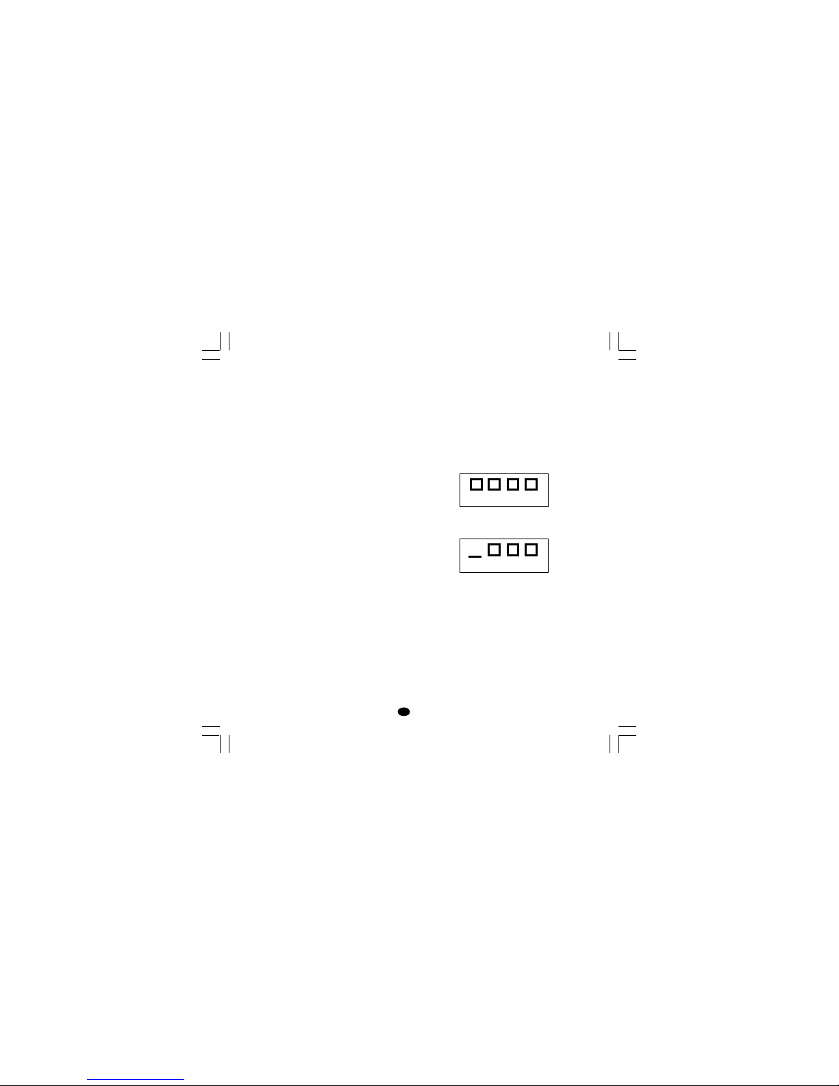
display as shown in the following figure:
An UNDERRANGE condition will be shown on
display as shown in the following figure:
When P41 is different from zero and an out of
range condition is detected, the instrument
operates in accordance with P41 and P42
parameters.
When P41 is equal to 0 (standard effect) and time
proportional outputs are configured, the following
conditions may occur:
- The instrument is set for one output only and an
OVERRANGE is detected, the OUT 1 turns OFF
(if reverse action) or ON (if direct action).
- The instrument is set for heating/cooling action
and an OVERRANGE is detected, OUT 1 turns
OFF and OUT 3 turns ON.
- From -100% to 100% when the device
is configured with two control outputs.
TOL Time duration of the output power
limiter
This parameter is not available when
P5 = SM.CL or SM.OL
Range: from 1 to 540 min.Above this
value the display shows “INF” meaning
that the limiting action is always on
Note: The TOL can be modified but the
new value will become operative only at
the next instrument start up.
RMP Control output max. rate of rise
This parameter is available when Pb is
different from zero.
Range: from 0.1 to 25.0 %/s.Above this
value the display shows “INF” meaning
that no ramp limitation is imposed.
F.CAL see "Feedback potentiometer calibration".
POS.L see "Feedback potentiometer calibration"
FB.LC see "Feedback potentiometer calibration"
POS.H see "Feedback potentiometer calibra-
tion"
FB.HC see "Feedback potentiometer calibration"
LFS-servo-1-02.p65 1/14/02, 3:44 PM27
Page 31

28
GB
- The instrument is set for one output only and an
UNDERRANGE is detected, the OUT 1 turns
ON (if reverse action) or OFF (if direct action).
- The instrument is set for heating/cooling action
and an UNDERRANGE is detected, OUT 1 turns
ON and OUT 3 turns OFF.
When P41 is equal to 0 (standard effect) and the
servomotor control output is configured, the
following conditions may occur:
- The instrument detects an OVERRANGE and a
reverse action is assigned to the servomotor output, the OUT 1 (s) turns OFF while OUT 2 (t)
turns ON.
- The instrument detects an OVERRANGE and a
direct action is assigned to the servomotor
output, the OUT 1 (s) turns ON while OUT 2
(t) turns OFF.
- The instrument detects an UNDERRANGE and a
reverse action is assigned to the servomotor output, the OUT 1 (s) turns ON while OUT 2 (t) turns
OFF.
- The instrument detects an UNDERRANGE and
a direct action is assigned to the servomotor
output, the OUT 1 (s) turns OFF while OUT 2
(t) turns ON.
The sensor leads break can be signalled as:
- for TC/mV input : OVERRANGE or
UNDERRANGE selected by
a solder jumper
- for mA/V input : UNDERRANGE
Note: On the mA/V input the leads break can be
detected only when the range selected has a zero
elevation (4/20 mA or 1/5 V or 2/10 V)
ERROR MESSAGES
The instrument performs same self-diagnostic
algorithm.
When an error is detected, the instrument shows
on the lower display the “Err” indication while the
upper display shows the code of the detected
error.
ERROR LIST
SEr Serial interface parameter error
100 Write EEPROM error.
150 CPU error.
200 Tentative to write on protected
memory.
201 - 2xx Configuration parameter error. The
two less significant digit’s shown the
number of the wrong parameter (ex.
209 Err show an Error on P9
parameter)
NOTE: When a configuration
parameter error is detected, it is
sufficient to repeat the configuration
procedure of the specify parameter.
299 Error in control outputs selection
301 Error on calibration of the selected
input
302 Feedback potentiometer calibration
error
NOTE: When an error 302 is
detected, push contemporarily the s
and t pushbuttons for loading the
default feedback potentiometer
calibration values then repeat the
feedback potentiometer calibration.
307 RJ input calibration error
400 Control parameters error
NOTE: If error 400 is detected, push
contemporarily the s and t
LFS-servo-1-02.p65 1/14/02, 3:44 PM28
Page 32

29
GB
pushbuttons for loading the default
parameters then repeat control
parameter setting.
500 Auto-zero error
501 Zero integrator error
502 RJ error
510 Error during calibration procedure
512 Error during feedback calibration
procedure.
NOTE: For all the other errors, contact your
supplier.
LFS-servo-1-02.p65 1/14/02, 3:44 PM29
Page 33

30
GB
harmonized standard EN 61010-1).
Installation category: II
Pollution degree: 2
Temperature drift: (CJ excluded)
< 200 ppm/°C of span for mV and TC ranges 1, 3, 5,
7, 21, 22, 23, 25.
< 300 ppm/°C of span for mA/V
< 400 ppm/°C of span for TC ranges 0, 2, 4, 6, 24.
< 500 ppm/°C of span TC ranges 8, 9, 26, 27.
< 800 ppm/°C of span TC ranges 10,28.
Operative temperature: from 0 to 50 °C.
Storage temperature : -20 to +70 °C
Humidity: from 20 % to 85% RH, non condensing.
Protections:
1) WATCH DOG circuit for automatic restart.
2) DIP SWITCH for protection against tampering
of calibration parameters.
INPUTS
A) THERMOCOUPLE
Type : L -J -K -T -N -R -S- B. °C/°F selectable.
External resistance: 100 Ω max, maximum error
0,1% of span.
Burn out: It is shown as an overrange condition
(standard). It is possible to obtain an underrange
indication by cut and short.
Cold junction: automatic compensation from 0 to
50 °C.
Cold junction accuracy : 0.1 °C/°C
Input impedance: > 1 MΩ
Calibration : according to IEC 584-1 and DIN
43710 - 1977.
GENERAL INFORMATIONS
GENERAL SPECIFICATIONS
Case: PC-ABS black color; self-extinguishing de-
gree: V-0 according to UL 94.
Front protection - designed and tested for IP 65 (*)
and NEMA 4X (*) for indoor locations (when panel
gasket is installed).
(*) Test were performed in accordance with CEI 701 and NEMA 250-1991 STD.
Installation: panel mounting.
Rear terminal block:15 screw terminals ( screw
M3, for cables from φ 0.25 to φ 2.5 mm
2
or from
AWG 22 to AWG 14 ) with connection diagrams
and safety rear cover.
Dimensions: DIN 43700 48 x 48 mm, depth 122mm.
Weight: 250 g.
Power supply:
- 100V to 240V AC 50/60Hz (-15% to + 10% of the
nominal value).
Power consumption: 6 W max.
Insulation resistance: > 100 MΩ according to
EN61010-1.
Dielectric strength: 2300 V rms according to
EN 61010-1.
Display updating time: 500 ms.
Sampling time: 250 ms for linear inputs
500 ms for TC input.
Accuracy:
+ 0,2% f.s.v.. + 1 digit @ 25 °C
ambient temperature.
Common mode rejection: 120 dB at 50/60 Hz.
Normal mode rejection: 60 dB at 50/60 Hz.
Electromagnetic compatibility and safety
requirements: This instrument is marked CE.
Therefore, it is conforming to council directives 89/
336/EEC (reference harmonized standard EN50081-2 and EN-50082-2) and to council
directives 73/23/EEC and 93/68/EEC (reference
LFS-servo-1-02.p65 1/14/02, 3:44 PM30
Page 34
31
GB
C) LINEAR INPUTS
Read-out: keyboard programmable between -1999
and +4000.
Decimal point: programmable in any position
Burn out: the instrument shows the burn out
condition as an underrange condition for 4-20 mA,
1-5 V and 2-10 V input types.
It shows the burn out condition as an underrange
or an overrange condition (selectable by soldering
jumper) for 0-60 mV and 12-60 mV input types. No
indication are available for 0-20 mA, 0-5 V and 010 V input types.
D) FEEDBACK POTENTIOMETER INPUT
Potentiometer: from 100 Ω to 1 kΩ.
E) LOGIC INPUTS
This instrument is provided of 2 opto-isolated logic
inputs. The logic input1 is used to select the
operative set point.
The logic input 2 function is used to select the
AUTO/MANUAL mode.
NOTES
1) The "serial comunication" and the "logic input"
options are mutually exclusive and can be
selected by a jumper setting.
2) Use an external contact with a contact rating
better than 0.5 mA, 5 V DC.
3) The instrument needs 100 ms to recognize a
contact status variation.
4) The logic inputs are isolated by the measuring
input.
SET POINTS
This instrument allows to use 2 set points: SP, SP2.
The set point selection is possible only by logic
inputs 1.
Set point transfer:
The transfer between one set point to another (or
between two different set point values) may be
realized by a step transfer or by a ramp with two
different programmable rate of change (ramp up
and ramp down).
Slope value: 1 - 100 eng. unit/min or step.
Set points limiter: RLO and RHI parameters, pro-
grammable.
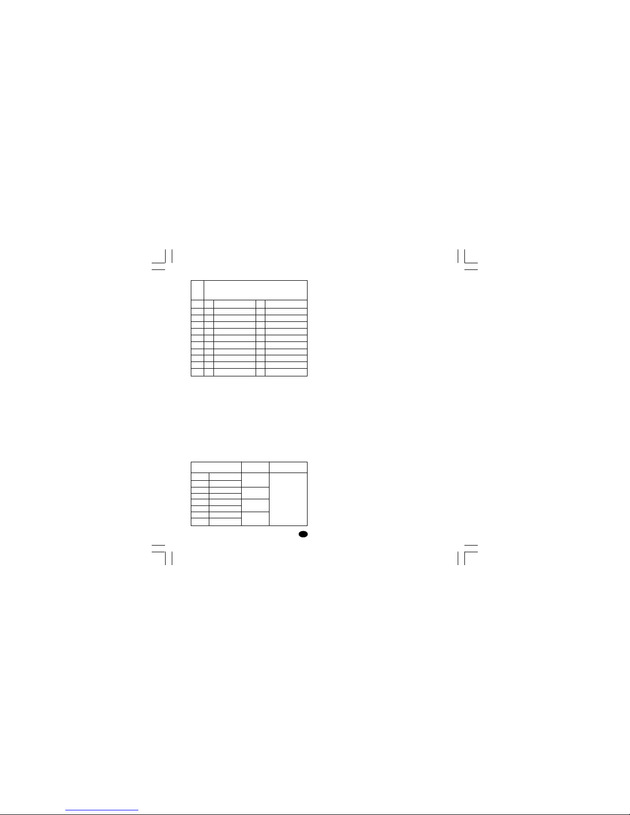
13
14
15
16
17
18
19
20
0 - 60 mV
12 - 60 mV
0 - 20 mA
4 - 20 mA
0 - 5 V
1 - 5 V
0 - 10 V
2 - 10 V
impedance
> 1 MΩ
< 5 Ω
> 400 kΩ
> 400 kΩ
Accuracy
0.2 % + 1 digit
@ 25°C
Input type
T/C
type
L
L
J
J
K
K
T
N
R
S
B
Ranges
0
1
2
3
4
5
6
7
8
9
10
0/ +400.0°C
0 / + 900°C
-100.0/ +400.0°C
-100/ + 1000°C
-100.0/ +400.0°C
-100/ + 1370°C
-199.9/ +400.0°C
-100/ + 1400°C
0 / + 1760°C
0 / + 1760°C
0 / +1820 °C
21
22
23
24
25
26
27
28
---
0 / + 1650 °F
---
-150/ + 1830 °F
---
-150/ + 2500 °F
-330/ + 750 °F
-150/ + 2550 °F
0 / + 3200 °F
0 / + 3200 °F
0 / + 3310 °F
LFS-servo-1-02.p65 1/14/02, 3:44 PM31
Page 35

32
GB
CONTROL ACTIONS
Control action: PID + SMART
Type: One (heating or cooling) or two (heating and
cooling) control outputs.
Proportional Band (Pb): from 1.0 to 200.0 % of
the input span.
When Pb=0, the control action becomes ON/OFF.
Hysteresis (for ON/OFF control action):
from 0.1% to 10.0% of the input span.
Integral time (Ti): from 1 s to 20 min. or excluded.
Derivative time (Td): from 1 s to 10 min.
If zero value is selected, the derivative action is
excluded.
Integral pre-load:
- from 0.0 to 100.0 % for one control output
- from -100.0 (cooling) to +100.0 % (heating) for
two control output.
SMART: keyboard enabling/disabling
Auto/Manual: selectable by front pushbutton.
Auto/Manual transfer: bumpless method type
Indicator "MAN" : OFF in auto mode and lit in
manual mode.
OUTPUTS
This instrument is equipped with four relay
outputs.
OUT 1 can be used either as servomotor output
(together OUT 2, both relays are interlocked) or as
independent relay output (in this case, OUT 2
cannot be used); OUT 3 and OUT 4 are
independent relay outputs.
The outputs can be programmed as follows:
Out 1 + Out 2 Out 3 OUT 4
interlocked relay relay
servomotor AL1 AL2+ AL3
Heating AL1 AL2+ AL3
Cooling AL1 AL2+ AL3
Heating Cooling AL2+ AL3
NOTE: alarm 2 and 3 are in OR condition on the
OUT 4 relay.
Control output updating time :
- 250 ms when a linear input is selected
- 500 ms when a TC input is selected.
Control output resolution: 0.1% of the span.
Direct/reverse action: programmable.
Output level indication (for control outputs):
The instrument displays separately the output 1
value and the output 2 value.
Output level limiter(for control outputs):
- For one control medium: from 0.0 to 100.0 % .
- For two control mediums: from -100.0 to +100.0%
This function may be operative at instrument start up
for a programmable time (To avoid thermal shock
and/or preheating the plant).
LFS-servo-1-02.p65 1/14/02, 3:44 PM32
Page 36

33
GB
Relay outputs
Outputs 1 and 2: 2 relay interlocked, SPST
contact with rated current 3 A at 250 V AC on
resistive load ( NO contact ).
Output 3: SPST contact with rated current 2 A at
250 V AC on resistive load.
Output 4: SPST contact with rated current 2 A at
250 V AC on resistive load.
NOTE: the side C of the OUT 3 and OUT 4 are
common.
Output status indication: 4 indicators (s, t,
OUT 3 and OUT 4) are lit when the respective
output is in ON condition.
ALARMS
Actions: Direct or reverse acting.
Alarm functions: each alarm can be configured
as process alarm, band alarm or deviation alarm.
Alarm reset: automatic or manual reset
programmable on each alarm.
Stand by (mask) alarm: each alarm can be
configured with or without stand by (mask)
function.
This function allows to delete false indication at
instrument start up and/or after a set point change.
Process alarm:
Operative mode : High or low programmable.
Threshold : programmable in engineering unit within
the input span.
Hysteresis: programmable from 0.1 % to 10.0 % of
the input span (P4 - P3).
Band alarm
Operative mode: Inside or outside programma-
ble.
Threshold : programmable from 0 to 500 units.
Hysteresis : programmable from 0.1 % to 10.0 % of
the input span.
Deviation alarm
Operative mode : High or low programmable.
Threshold : programmable from - 500 to +500
units.
Hysteresis : programmable from 0.1 % to 10.0 % of
the input span.
SERIAL COMMUNICATION INTERFACE
Type: RS-485
Protocol type: MODBUS, JBUS, ERO polling/
selecting.
Baud rate: programmable from 600 to 19200
BAUD.
Byte format: 7 or 8 bit programmable.
Parity: even, odd or none programmable.
Stop bit : one.
Address :
- from 1 to 95 for ERO protocol
- from 1 to 255 for all the other protocols
Output voltage levels: according to EIA standard.
NOTE: The "serial comunication" and the "logic
input" options are mutually exclusive and can be
selected by a jumper setting.
LFS-servo-1-02.p65 1/14/02, 3:44 PM33
Page 37

34
GB
MAINTENANCE
1) REMOVE POWER FROM THE POWER
SUPPLY TERMINALS AND FROM RELAY
OUTPUT TERMINALS
2) Remove the instrument from case.
3) Using a vacuum cleaner or a compressed air jet
(max. 3 kg/cm
2
) remove all deposit of dust and
dirt which may be present on the louvers and
on the internal circuits trying to be careful for
not damage the electronic components.
4) To clean external plastic or rubber parts use
only a cloth moistened with:
- Ethyl Alcohol (pure or denatured) [C
2H5
OH] or
- Isopropil Alcohol (pure or denatured)
[(CH
3)2
CHOH] or
- Water (H
2
O)
5) Verify that there are no loose terminals.
6) Before re-inserting the instrument in its case, be
sure that it is perfectly dry.
7) re-insert the instrument and turn it ON.
LFS-servo-1-02.p65 1/14/02, 3:44 PM34
Page 38
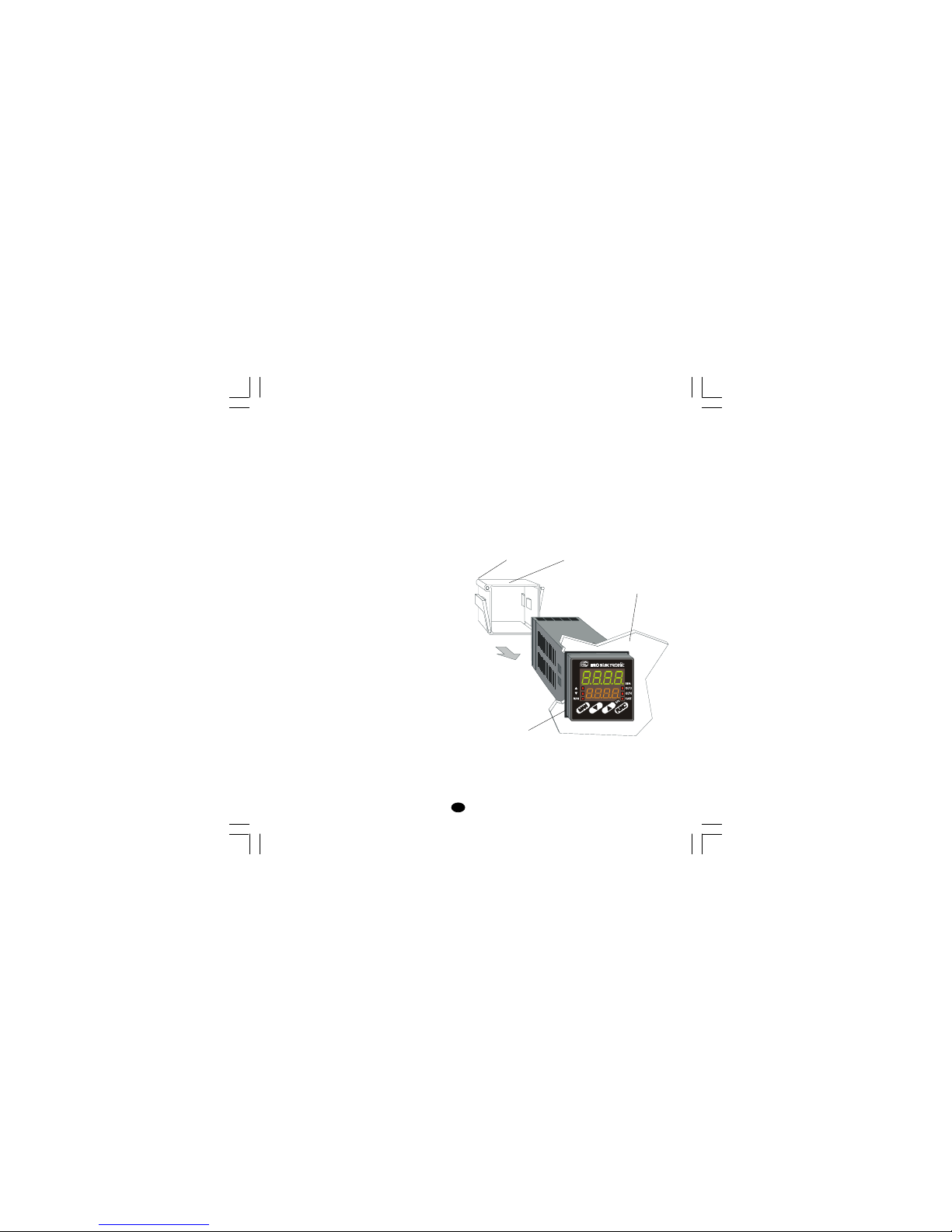
1
I
MONTAGGIO
Scegliere una posizione di montaggio pulita,
facilmente accessibile anche sul retro e
possibilmente esente da vibrazioni. La temperatura ambiente deve essere compresa tra 0 e 50 °C.
Lo strumento può essere montato su un pannello
di spessore fino a 15 mm dopo aver eseguito un
foro rettangolare da 45 x 45 mm.
Per le dimensioni di ingombro e foratura vedere
Fig. 2.
La rugosità superficiale del pannello deve essere
migliore di 6,3 µm.
Lo strumento è fornito di guarnizione in gomma
da pannello (da 50 a 60 Sh).
Per garantire la protezione IP65 e NEMA 4,
inserire la guarnizione, fornita con l'apparecchio,
tra lo strumento ed il pannello (vedere figura 1).
Per fissare lo strumento al pannello, procedere
come segue:
1) infilare la guarnizione sulla custodia dello
strumento.
2) inserire lo strumento nella foratura
3) mantenendo lo strumento ben appoggiato al
pannello, inserire la bretella di fissaggio.
4) utilizzando un cacciavite, serrare le viti con una
coppia compresa tra 0.3 e 0.4 Nm.
vite
Fig. 1
bretella
pannello
guarnizione
LFS-servo-4-02.p65 1/14/02, 3:46 PM1
Page 39
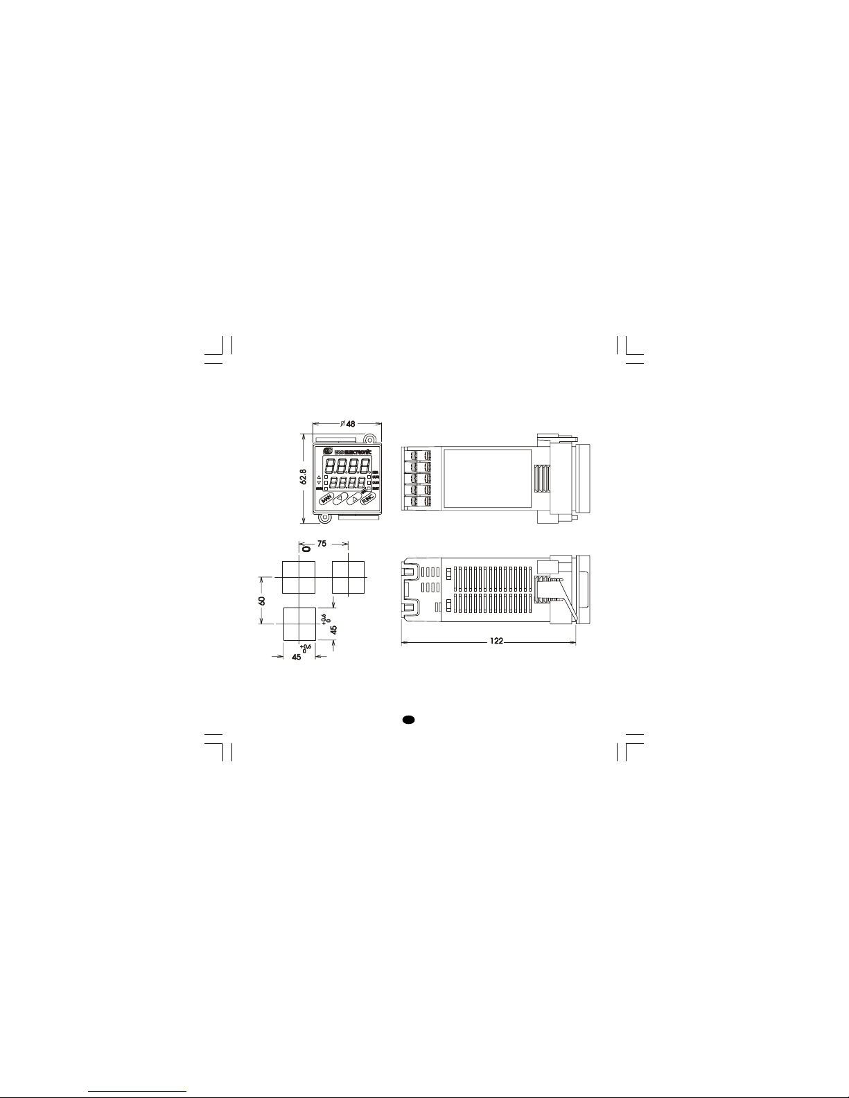
2
I
Fig. 2
DIMENSIONI E FORATURA
LFS-servo-4-02.p65 1/14/02, 3:46 PM2
Page 40
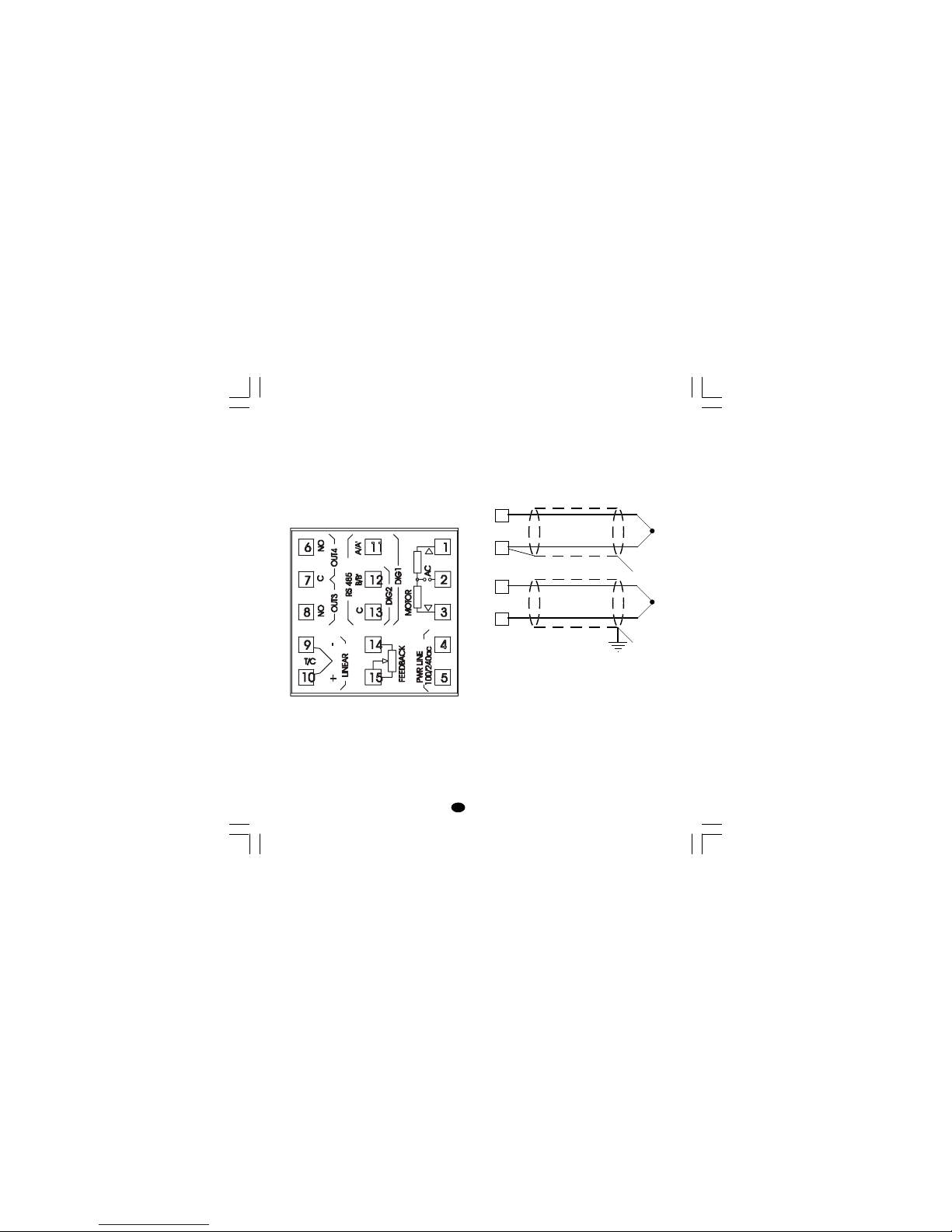
3
I
COLLEGAMENTI ELETTRICI
I collegamenti devono essere effettuati dopo che
la custodia dello strumento è stata regolarmente
montata sul pannello.
Fig. 3 MORSETTIERA POSTERIORE
A) INGRESSI DI MISURA
NOTA: Componenti esterni (es. barriere zener)
collegati tra il sensore ed i terminali di ingresso dello
strumento possono causare errori di misura dovuti
ad una impedenza troppo elevata o non bilanciata
oppure alla presenza di correnti di perdita.
INGRESSO PER TERMOCOPPIA
Fig. 4 COLLEGAMENTO DI TERMOCOPPIE
NOTE:
1) Non posare i cavi dei segnali parallelamente o
vicino a cavi di potenza o a sorgenti di disturbi.
2) Per il collegamento della TC usare cavo di
compensazione/estensione appropriato,
preferibilmente schermato.
3) Quando si usa cavo schermato, lo schermo
deve essere collegato a terra ad una sola
estremità.
10
9
+
_
10
9
+
_
schermo
schermo
LFS-servo-4-02.p65 1/14/02, 3:46 PM3
Page 41
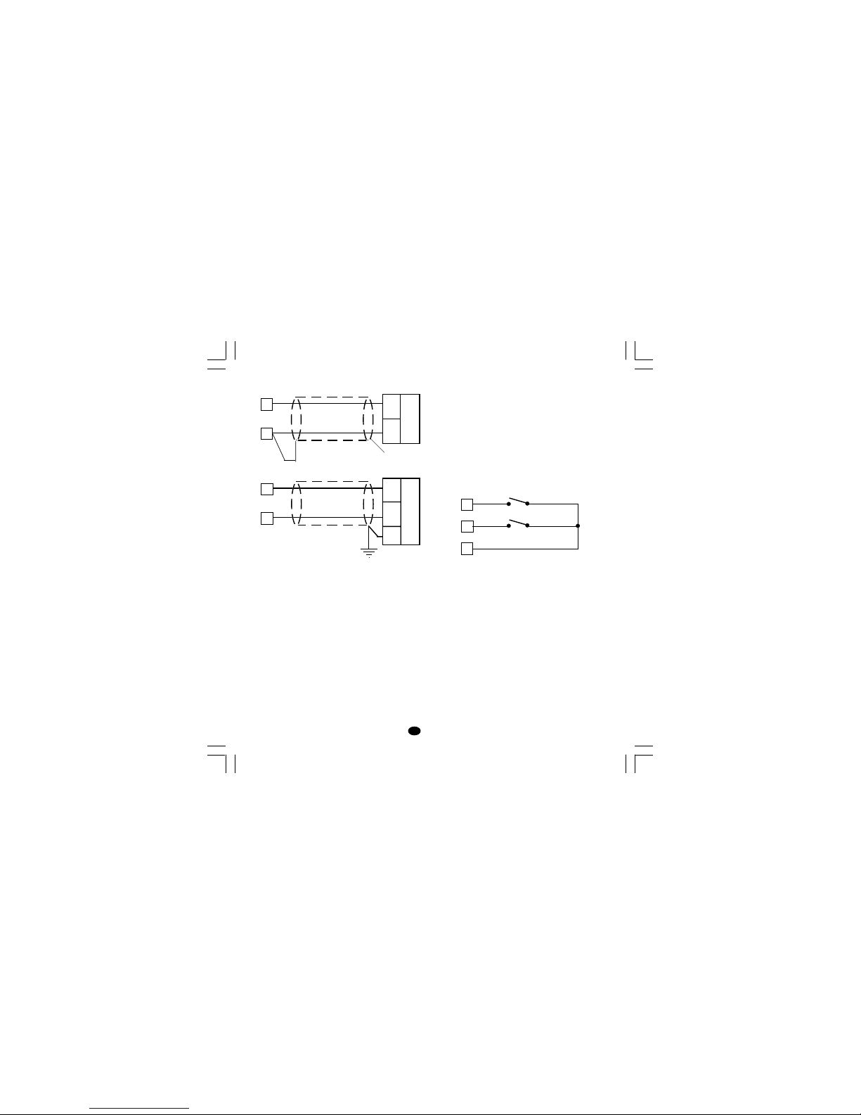
4
I
INGRESSO LINEARE
Fig. 5 COLLEGAMENTO PER INGRESSI IN
mA, mV o V
NOTE:
1) Non posare i cavi dei segnali parallelamente o
vicino a cavi di potenza o a sorgenti di disturbi.
2) Fare attenzione alla resistenza di linea, una
resistenza di linea eccessivamente alta può
causare errori di misura.
3) Quando si usa cavo schermato, lo schermo
deve essere collegato a terra ad una sola
estremità.
4) L'impedenza di ingresso è pari a:
< 5 Ω per ingesso 20 mA
> 1 MΩ per ingresso 60 mV
> 400 kΩ per ingresso 5 V
> 400 kΩ per ingresso 10 V
INGRESSI LOGICI
NOTE:
1) Le opzioni "interfaccia seriale" e "ingressi logici"
sono mutuamente esclusive.
2) Non posare i cavi dei segnali parallelamente o
vicino a cavi di potenza o a sorgenti di disturbi.
3) Utilizzare un contatto esterno adatto per una
portata di 0.5 mA, 5 V c.c.
4) Lo strumento controlla ogni 100 ms lo stato dei
contatti.
5) Gli ingressi logici sono isolati dall'ingresso di
misura.
Fig. 7 COLLEGAMENTO DEGLI
INGRESSI LOGICI
Questi strumenti sono provvisti di 2 ingressi logici.
L'ingresso logico 1 consente di selezionare il set
point operativo come incato dalla tabella
seguente:
in. logico 1 set point operat.
aperto SP
chiuso SP2
L'ingresso logico 2 consente di selezionare il
modo AUTO o MANUALE (vedere anche il
parametro P24).
in. logico 2 modo operat.
aperto AUTO
chiuso MANUALE
schermo
_
+
mA,
mV
o
V
9
+
_
G
mA
mV
o
V
10
9
10
11
Log. input 1
12
13
Log. input 2
LFS-servo-4-02.p65 1/14/02, 3:46 PM4
Page 42
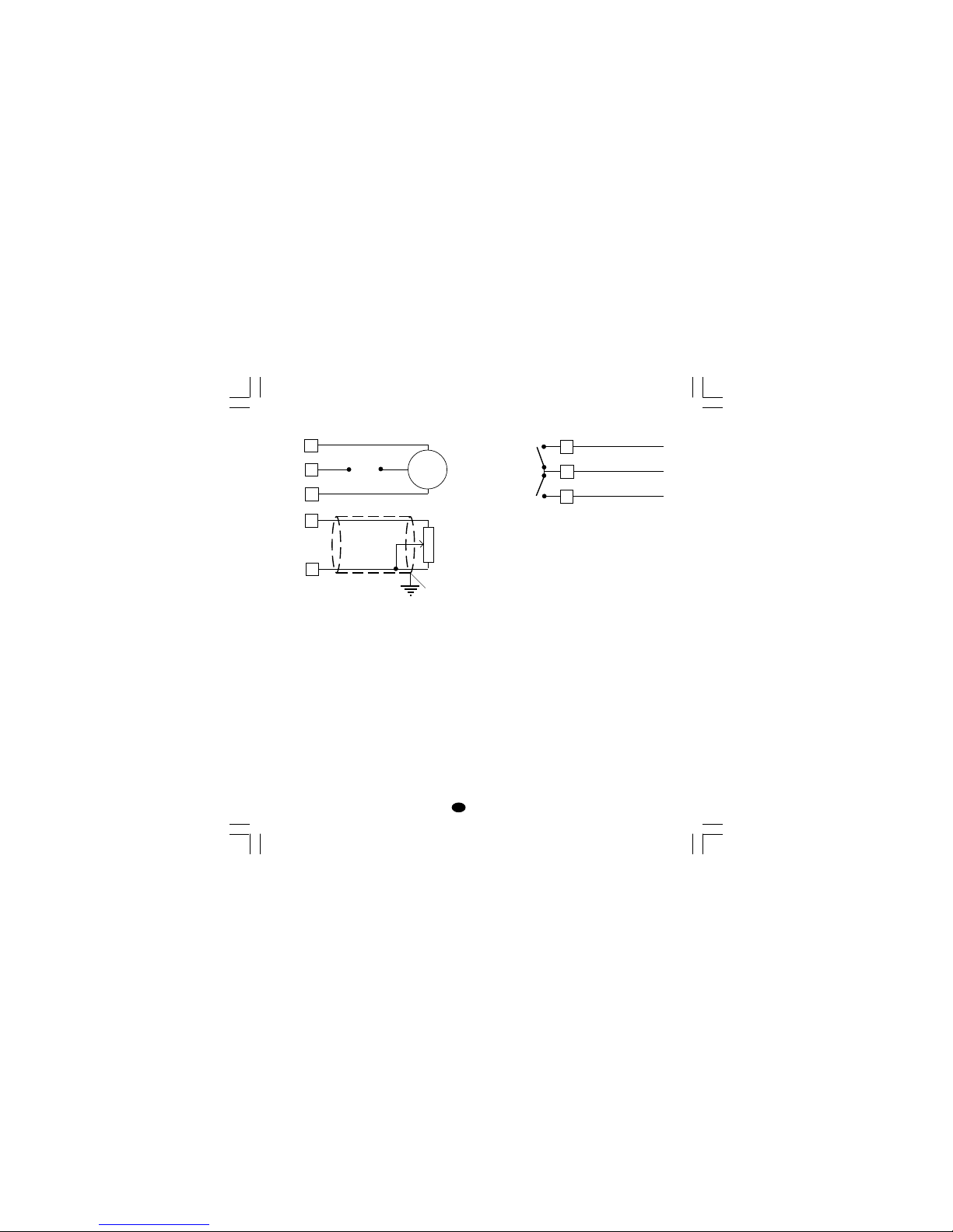
5
I
USCITA SERVOMOTORE.
Fig. 8 COLLEGAMENTO DELL'USCITA PER
SERVOMOTORE
Le due uscite a relè sono interbloccate.
NOTE:
1) Prima di collegare lo strumento alla linea di
potenza, assicurarsi che la tensione di linea e la
corrente assorbita sia conforme alla portata dei
contatti (3 A/ 250 V c.a. con carico resistivo).
2) Per evitare rischi, collegare la linea di potenza
solo dopo aver eseguito tutti gli altri collegamenti.
3) Per il collegamento del servomotore utilizzare
cavo No 16 AWG o superiore adatti per una
temperatura di almeno 75 °C.
4) Utilizzare solo conduttori di rame.
5) Non posare i cavi di potenza parallelamente o
vicino a cavi dei segnali o a sorgenti di disturbi.
6) Per il collegamento del potenziometro di
controreazione utilizzare un cavo schermato con
lo schermo collegato da un solo lato.
7) Le uscite a relè sono protette da varistor contro
carichi con componente induttiva fino a 0.5 A.
1
2
3
Servo-
motore
s (apre la valvola)
t (chiude la
valvola)
Rete
14
15
Potenziometro di
controreazione
Schermo
USCITE A RELE'
Fig. 9 COLLEGAMENTO DELLE USCITE A
RELE
NOTA: L'uscita 1 può essere usata come uscita
per servomotore oppure come uscita relè
a tempo proporzionale; tramite il
parametro P5, (vedere pag.11) è possibile
impostare l'uscita desiderata.
Tutte le uscite a relè sono protette, tramite varistori,
verso carichi che abbiano componente induttiva fino
a 0,5 A.
La portata del contatto dell'uscita 3 e 4 è 2A/250V
AC su carico resistivo.
Il numero delle operazioni è pari a 1 x 10
5
alla
portata specificata.
Gli allarmi 2 e 3 sono in OR sull'uscita 4.
Le raccomandazioni che seguono possono
evitare seri problemi causati dal utilizzo delle
uscite a relè per pilotare carichi induttivi
8
6
7
C - OUT 3/4
NO - OUT 4
NO - OUT 3
OUT 4
OUT 3
LFS-servo-4-02.p65 1/14/02, 3:46 PM5
Page 43
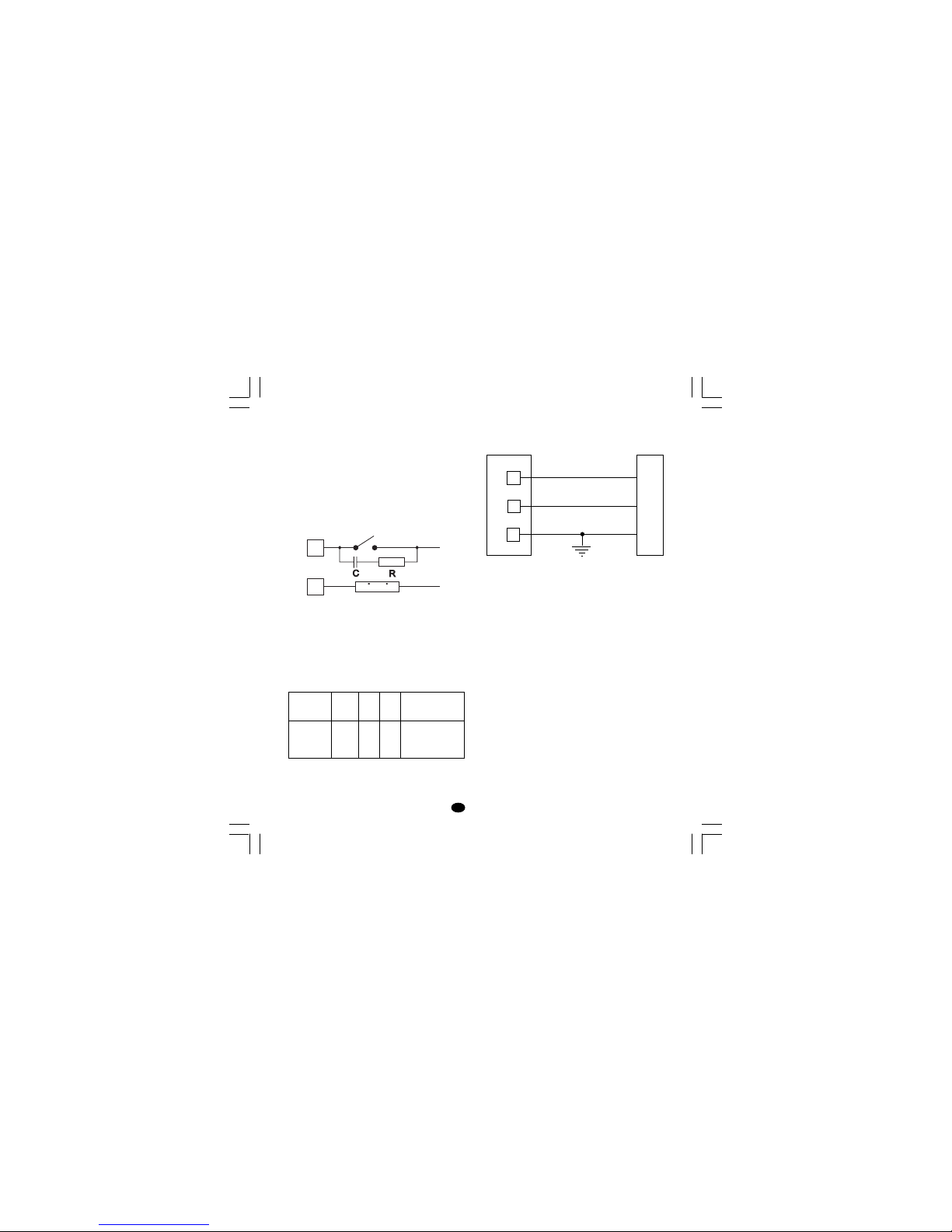
6
I
CARICHI INDUTTIVI
Nella commutazione di carichi induttivi si possono
generare transitori e disturbi che possono pregiudicare le prestazioni dello strumento.
Le protezioni interne (varistori) assicurano la
protezione dai disturbi per carichi aventi una
componente induttiva fino a 0,5 A.
Problemi analoghi possono essere generati dalla
commutazione di carichi tramite un contatto
esterno in serie al contatto di uscita dello
strumento.
Fig. 10 CONTATTO ESTERNO IN SERIE AL
CONTATTO DI USCITA DELLO STRUMENTO
In questi casi si raccomanda di collegare un filtro
RC in parallelo al contatto esterno come indicato
in fig. 10.
Il valore della capacità (C) e del resistore (R)
sono indicati nella tabella seguente.
In tutti i casi i cavi collegati con le uscite a relè
devono rimanere il più lontano possibile dai cavi
dei segnali.
INTERFACCIA SERIALE
L'interfaccia tipo RS-485 consente di collegare un
massimo di 30 unità ad una sola unità master.
Fig. 11 - COLLEGAMENTO DELL'INTERFACCIA
RS-485
I cavi di collegamento non devono superare i
1500 metri con una velocità di trasmissione pari a
9600 BAUD.
NOTA: Riportiamo di seguito la definizione data
dalle norme EIA per le interfacce RS-422 e
RS-485 in merito al significato ed al senso
della tensione presente sui morsetti.
a) Il morsetto ” A ” del generatore deve
essere negativo rispetto al morsetto ”
B ” per stato binario 1 (MARK o OFF).
b) Il morsetto ” A ” del generatore deve
essere positivo rispetto al morsetto ” B
” per stato binario 0 (SPACE o ON).
Carico ind.
(mA)
<40 mA
<150 mA
<0.5 A
C
(µF)
0.047
0.1
0.33
R
(Ω)
100
22
47
P.
(W)
1/2
2
2
Tensione di
lavoro
260 V AC
260 V AC
260 V AC
12
13
COMMON
11
B'/B
B/B'
A/A'
A'/A
M
A
S
T
E
R
I
N
S
T
R
U
M
E
N
T
CARICO
RETE
LFS-servo-4-02.p65 1/14/02, 3:46 PM6
Page 44
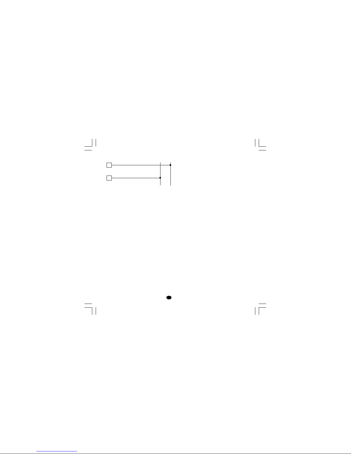
7
I
ALIMENTAZIONE
Fig. 12 COLLEGAMENTO ALL'ALIMENTAZIONE
NOTE:
1) Prima di collegare lo strumento alla rete,
assicurarsi che la tensione di linea sia
corrispondente a quanto indicato nella targa di
identificazione dello strumento.
2) Per evitare il rischio di scosse elettriche
collegare l'alimentazione solo dopo aver
effettuato tutti gli altri collegamenti.
3) Per il collegamento alla rete, utilizzare cavi No
16 AWG o maggiori adatti per una temperatura
di almeno 75 °C.
4) Utilizzare solo conduttori di rame.
5) Non posare i cavi dei segnali parallelamente o
vicino a cavi di potenza o a sorgenti di disturbi.
6) Per l'alimentazione 24 V c.c. la polarità non ha
importanza.
7) I circuiti di alimentazione sono protetti da un
fusibile sub miniatura di tipo T, 1 A, 250 V.
Se il fusibile dovesse risultare danneggiato, è
consigliabile far verificare l'intero circuito di
alimentazione. Per questa ragione si consiglia
di spedire l'apparecchio al fornitore.
8) Le normative sulla sicurezza relative ad
apparecchiature collegate permanentemente
all'alimentazione richiedono:
- un interruttore o disgiuntore va compreso
nell'impianto elettrico dell'edificio;
- esso deve trovarsi in stretta vicinanza
dell'apparecchio ed essere facilmente
raggiungibile da parte dell'operatore;
- deve essere marcato come il dispositivo di
interruzione dell'apparecchio.
NOTA: un singolo interruttore o disgiuntore può
comandare più apparecchi.
9) Se l'alimentazione prevede il neutro, collegarlo al
terminale 5.
R (S,T)
R (S,T)
N
N
Rete
da 100 V a 240 V c.a. (50/60Hz)
4
5
LFS-servo-4-02.p65 1/14/02, 3:46 PM7
Page 45
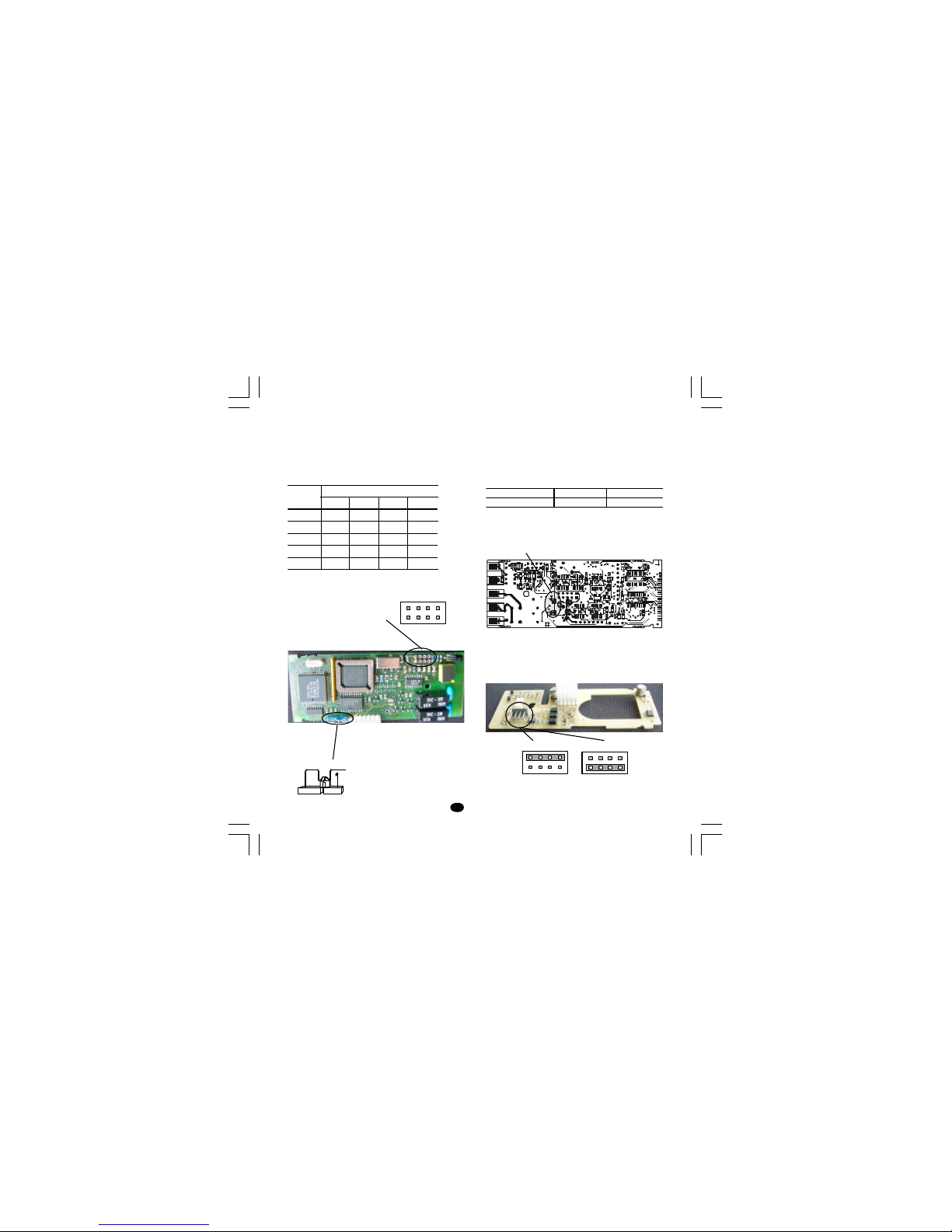
8
I
IMPOSTAZIONI HARDWARE
PRELIMINARI
1) Estrarre lo strumento dalla custodia.
2) Selezionare il tipo di ingresso desiderato
impostando il ponticello J1 come indicato nella
tabella seguente:
Tipo di J1
ingresso 1-2 3-4 5-6 7-8
TC chiuso aperto aperto aperto
60 mV chiuso aperto aperto aperto
5 V aperto chiuso aperto aperto
10 V aperto aperto chiuso aperto
20 mA aperto aperto aperto chiuso
APERTURA DEL CIRCUITO DI INGRESSO
Questi strumenti sono in grado di rilevare
l'apertura del circuito di ingresso.
Per gli ingressi da TC, è possibile selezionare il
tipo di indicazione modificando l'impostazione dei
ponticelli CH1 ed SH1 nel modo seguente:
Overrange (std) CH1 = chiuso SH1 = aperto
Underrange CH1 = aperto SH1 = chiuso
i ponticelli CH1 ed SH1 sono posizionati sul lato a
saldare della scheda CPU.
Selezione Ingressi logici o interfaccia seriale
Se lo strumento è dotato di entrambe le funzioni,
selezionare la funzione desiderata tramite J105:
Fig. 15Fig. 13
Fig. 14
SH1 CH1
SW1
1 3 5 7
2 4 6 8
J1
J105
Logic inputs
1 3 5 7
2 4 6 8
1 3 5 7
2 4 6 8
RS-485
Nuovo-2 15/09/2005, 9.498
Page 46

9
I
CONFIGURAZIONE DELLO STRUMENTO
1) Accendere lo strumento.
Lo strumento visualizza il valore misurato sul
display superiore ed il set point su quello
inferiore (questo stato viene chiamato "modo
normale di visualizzazione")
2) Premere il tasto "FUNC" e, mantenendolo
premuto, premere anche il tasto "MAN" per più
di 4 secondi.
Il display inferiore mostrerà "ConF" mentre il
display superiore mostrerà "C.mOn".
NOTA: è possibile scegliere tra:
A) modo Verifica: in questo modo è possibile
verificare ma non modificare i parametri di
configurazione.
Durante il modo verifica lo strumento
continua ad eseguire la regolazione.
B) modo modifica: in questo modo è possibile
modificare i parametri di configurazione.
Durante il modo modifica l'azione regolante
è disabilitata.
3) Tramite i tasti s o t selezionare l'indicazione
"C.mOd" (modo modifica).
4) Premere il tasto "FUNC".
NOTE:
1) Quando il modo "modifica" è stato avviato, lo
strumento interrompe l'azione regolante e:
- imposta le uscite regolanti a OFF;
- disattiva gli allarmi;
- disabilita la linea seriale
2) Se i parametri di configurazione sono protetti da
un codice di sicurezza, il display mostrerà:
Tramite il tasto s o t impostare un valore
uguale al codice di sicurezza (vedere il
parametro P51) o il codice passe-partout
(vedere appendix A).
Nota: il codice passe-partout permette di accedere al modo modifica dei parametri di configurazione anche se è stato dimenticato il codice di sicurezza oppure anche quando i parametri sono
sempre protetti (P51 = 1).
Quando si desidera uscire dal modo modifica dei
parametri di configurazione, procedere nel modo
seguente:
a) premere il tasto "FUNC" oppure "MAN" più
volte fino a visualizzare l'indicazione "C.End".
b) Premere il tasto ”s” oppure “t” per seleziona-
re l'indicazione "YES".
c) Premere il tasto “FUNC”. Lo strumento esce dal
modo modifica dei parametri di configurazione,
esegue un reset automatico e ritorna nel modo
normale di visualizzazione.
Funzionalità dei tasti nel modo di configurazione
FUNC = Consente di memorizzare il nuovo
valore del parametro selezionato e
passare al parametro successivo
(ordine crescente).
MAN = Consente di visualizzare i parametri in
ordine decrescente senza memorizzare
i nuovi valori.
s = Consente di aumentare il valore del
parametro selezionato.
t = Consente di diminuire il valore del
parametro selezionato.
LFS-servo-4-02.p65 1/14/02, 3:46 PM9
Page 47

10
I
PARAMETRI DI CONFIGURAZIONE
Note:
1) Nelle pagine seguenti verrà descritta la
sequenza completa dei parametri, ma lo
strumento mostrerà solo i parametri relativi
all'hardware specifico e alla configurazione
precedentemente impostata (es. impostando
OUT 3 (P7) = nonE, tutti i parametri relativi a
questa uscita non verranno visualizzati).
2) Durante la configurazione dei parametri nel
modo modifica, il display inferiore mostra il
codice mnemonico del parametro selezionato,
mentre il display superiore mostra il valore o lo
stato assegnato al parametro selezionato.
dF.CndF.Cn
dF.CndF.Cn
dF.Cn = Caricamento dei parametri di default
Se lo strumento è in modo "Verifica", questo
parametro non verrà visualizzato
OFF = Nessun caricamento dei dati
tb1 = Caricamento dei parametri della tabella
Europea (Tb.1).
tb2 = Caricamento dei parametri della tabella
Americana (Tb.2).
NOTA: nell'appendice A è riportata la lista delle
due tabelle dei parametri di default.
SEr1SEr1
SEr1SEr1
SEr1 = Protocollo di comunicazione seriale
OFF = Comunicazione seriale non utilizzata
Ero = Polling/selecting ERO
nbUS = Modbus
jbUS = Jbus
NOTA: Le opzioni "interfaccia seriale" e "ingressi
logici" sono mutuamente esclusive e selezionabili
tramite jumper
SEr2SEr2
SEr2SEr2
SEr2 = Indirizzo per la comunicazione seriale
Non disponibile quando SEr1 = OFF
Campo: da 1 a 95 per il protocollo ERO.
da 1 a 255 per tutti gli altri protocolli.
NOTA: L'interfaccia seriale tipo RS 485 consente di
collegare sulla stessa linea un massimo di 31 strumenti.
SEr3SEr3
SEr3SEr3
SEr3 = Velocità di trasmissione dei dati
Non disponibile quando SEr1 = OFF
Campo: da 600 a 19200 baud.
NOTA: i 19200 baud vengono visualizzati con 19.2.
SEr4SEr4
SEr4SEr4
SEr4 = Formato della comunicazione seriale
Non disponibile quando SEr1 = OFF
7E = 7 bit + bit di parità (solo protocollo ERO)
7O = 7 bit + bit di disparità (solo protocollo ERO)
8E = 8 bit + bit di parità
8O = 8 bit + bit di disparità
8 = 8 bit senza parità
P1 - Tipo di ingresso e campo di misura
0 = TC tipo L campo 0 / +400.0 °C
1 = TC tipo L campo 0 / +900 °C
2 = TC tipo J campo-100.0 / +400.0 °C
3 = TC tipo J campo -100 / +1000 °C
4 = TC tipo K campo-100.0 / +400.0 °C
5 = TC tipo K campo -100 / +1370 °C
6 = TC tipo T Campo-199.9 / +400.0 °C
7 = TC tipo N campo -100 / +1400 °C
8 = TC tipo R campo 0 / +1760 °C
9 = TC tipo S campo 0 / +1760 °C
10 = TC tipo B campo 0 / 1820 °C
13 = mV Lineare campo 0 / 60 mV
14 = mV Lineare campo 12 / 60 mV
15 = mA Lineare campo 0 / 20 mA
16 = mA Lineare campo 4 / 20 mA
17 = V Lineare campo 0 / 5 V
18 = V Lineare campo 1 / 5 V
19 = V Lineare campo 0 / 10 V
20 = V Lineare campo 2 / 10 V
LFS-servo-4-02.p65 1/14/02, 3:46 PM10
Page 48

11
I
21 = TC tipo L campo 0 / +1650 °F
22 = TC tipo J campo -150 / +1830 °F
23 = TC tipo K campo -150 / +2500 °F
24 = TC tipo T campo -330 / +750 °F
25 = TC tipo N campo -150 / +2550 °F
26 = TC tipo R campo 0 / +3200 °F
27 = TC tipo S campo 0 / +3200 °F
28 = TC tipo B campo 0 / 3310 °F
NOTE: impostando P1 = 0, 2, 4, 6, 10 or 28, lo
strumento imposta automaticamente P43 = FLtr.
Per tutti gli altri campi P43 = nOFL.
P2 = Posizione punto decimale
Questo parametro è disponibile solo per gli ingressi
lineari (P1 = 13, 14, 15, 16, 17, 18, 19 o 20).
----. = Nessuna cifra decimale.
---.- = Una cifra decimale.
--.-- = Due cifre decimali.
-.--- = Tre cifre decimali.
P3 = Valore di inizio scala
Per gli ingressi lineari, P3 è programmabile da
-1999 a 4000 e il valore di P3 puo essere
superiore al valore di P4 per ottenere una
scala di visualizzazione inversa.
Per gli ingressi da TC, P3 è programmabile
all'interno del campo di ingresso.
Quando P3 viene modificato, lo strumento
assegna automaticamente al parametro rL il
nuovo valore di P3.
P4 = Valore di fondo scala.
Per gli ingressi lineari, P4 è programmabile da
-1999 a 4000.
Per gli ingressi da TC, P4 è programmabile all'inter-
no del campo di ingresso.
Quando il parametro P4 viene modificato, lo
strumento assegna automaticamente al parametro
rH il nuovo valore di P4.
t
Ingresso
t
Uscita
t
Ingresso
t
Uscita
Inversa Diretta
I valori di inizio e fondo scala vengono utilizzati
dall'algoritmo PID, dalla funzione SMART e dalle
funzioni allarmi per calcolare l'ampiezza del campo
di lavoro.
NOTE: L'ampiezza minima del campo di lavoro (S =
P4 - P3), in valore assoluto, deve risultare pari a:
Per ingressi lineari, S
> 100 unità.
Per ingressi da TC con indicazione °C , S
> 300 °C.
Per ingressi da TC con indicazione °F , S
> 550 °F.
P5 = Tipo di uscita 1
Sn.OL= servomotore ad anello aperto
Sn.CL= servomotore ad anello chiuso.
rEU = uscita a tempo proporzionale con azione
inversa
dir = uscita a tempo proporzionale con azione
diretta.
NOTE:
1) impostando P5 uguale a "Sm.OL" o
deselezionando l'opzione "Sm.OL", il parametro
P41 verrà forzato al valore 0.
2) imponendo P5 uguale a "rEU", il relativo tempo
di ciclo (CY1) verrà forzato a 15 s.
3) impostando P5 uguale a "dir", il relativo
tempo di ciclo (CY1) verrà forzato a:
10 s se P25 = Air
4 s se P25 = OIL
2 s se P25 = H2O
LFS-servo-4-02.p65 1/14/02, 3:46 PM11
Page 49

12
I
P6 = Indicazione della posizione valvola.
Questo parametro è disponibile solo se P5 = Sm.OL.
Fb = la posizione valvola verrà visualizzata
no.Fb = la posizione valvola NON verrà
visualizzata (omettere il potenziometro di
controreazione)
P7 = Funzione dell'uscita 3.
nonE = uscita non utilizzata.
AL1.P = uscita dell'allarme 1 con allarme 1
programmato come allarme di processo.
AL1.b = uscita dell'allarme 1 con allarme 1
programmato come allarme di banda.
AL1.d = uscita dell'allarme 1 con allarme 1
programmato come allarme di deviazione
rEU = seconda uscita regolante con azione
inversa.
dir = seconda uscita regolante con azione diretta
NOTE:
1) Se P7 viene modificato in "rEU" il relativo tempo
di ciclo (Cy3) verrà forzato a 15 s
2) Se P7 viene modificato in "dir" il relativo tempo
di ciclo verrà forzato a: 10 s se P25 =Air
4 s se P25 = OIL
2 s se P25 = H2O
3) Solo uno delle due uscite può essere impostato
come uscita "rEU" (vedere P5 e P7).
4) Solo uno delle due uscite può essere impostato
come uscita "dir" (vedere P5 e P7).
5) Se è stata selezionata l'uscita servomotore
(P5 ="Sm.OL" o "Sm.CL"), l'uscita 3 può essere
impostata solo come uscita di allarme (P7 =
"AL1.P" o "AL1.b" o "AL1.d").
P8 = Modo operativo dell'allarme 1
Disponibile solo se P7 è uguale a AL1.P, AL1.b o
AL1.d.
H.A. = di massima (fuori banda) con reset automatico.
L.A. = di minima (dentro la banda) con reset
automatico.
H.L. = di massima (fuori banda) con reset manuale.
L.L. = di minima (dentro la banda) con reset manuale.
P9 = Funzione dell'allarme 2 (OUT 4).
nonE = uscita non utilizzata.
AL2.P = uscita dell'allarme 2 con allarme 2
programmato come allarme di processo.
AL2.b = uscita dell'allarme 2 con allarme 2
programmato come allarme di banda.
AL2.d = uscita dell'allarme 2 con allarme 2 pro-
grammato come allarme di deviazione.
NOTA: L'uscita 4 si comporterà come un OR
logico tra gli allarmi 2 e 3.
P10 = Modo operativo allarme 2
Disponibile se P9 è diverso da "nonE".
H.A.= di massima (fuori banda) con reset
automatico
L.A. = di minima (dentro la banda) con reset
automatico.
H.L. = di massima (fuori banda) con reset manuale.
L.L. = di minima (dentro la banda) con reset manuale.
P11 = Funzione dell'allarme 3 (OUT 4).
nonE = uscita non utilizzata.
AL3.P = uscita dell'allarme 3 con allarme 3
programmato come allarme di processo.
AL3.b = uscita dell'allarme 3 con allarme 3
programmato come allarme di banda.
AL3.d = uscita dell'allarme 3 con allarme 3
programmato come allarme di deviazione
NOTA: L'uscita 4 si comporterà come un OR
logico tra gli allarmi 2 e 3.
P12 = Modo operativo dell'allarme 3
Disponibile solo quando P11 è diverso da "nonE".
H.A. = di massima (fuori banda) con reset automati-
co.
L.A. = di minima (dentro la banda) reset automatico.
LFS-servo-4-02.p65 1/14/02, 3:47 PM12
Page 50

13
I
H.L. = di massima (fuori banda) con reset manuale.
L.L. = di minima (dentro la banda) con reset manua-
le.
P13 = Programmabilità della soglia e
dell'isteresi dell'allarme 3.
Disponibile solo se P11 è diverso da "nonE".
OPrt = La soglia di allarme e l'isteresi dell'allar-
me 3 sono modificabili durante il modo
operativo.
COnF = La soglia di allarme e l'isteresi dell'allar-
me 3 sono modificabili durante il modo
configurazione.
SPEC= Durante la configurazione l'utente imposta
l'isteresi e due valori di soglia dell'allarme 3.
Durante il modo operativo, l'utente potrà
selezionare il primo od il secondo valore
di soglia come valore operativo.
P14 = Primo valore di soglia dell'allarme 3
Disponibile solo se P11 è diverso da "none" e
P13 è uguale a "COnF" o "SPEC".
Campo:
- Per allarme di processo - all'interno del campo
di ingresso.
- Per allarme di banda - da 0 a 500 unità.
- Per allarmi di deviazione - da -500 a 500 unità
P15 = Secondo valore di soglia dell'allarme 3
Disponibile solo se P11 è diverso da "none" e
P13 è uguale a "SPEC".
Campo:
- Per allarme di processo - all'interno del campo
di ingresso.
- Per allarme di banda - da 0 a 500 unità.
- Per allarmi di deviazione - da -500 a 500 unità
P16 = Isteresi allarme 3
Disponibile solo se P11 è diverso da "nonE" e
P13 è uguale a "COnF" o "SPEC".
Campo (in unità ingegneristiche) da 1 a l minore
trà 250 e l'ampiezza del campo programmato
(P3-P4).
Nota: Se l'isteresi di un allarme di banda risulta più
grande della banda impostata, lo strumento utilizzerà un valore di isteresi pari al valore di banda meno
1 digit.
P17 = Soglia della funzione SOFT START.
Disponibile solo se P5 è diverso da "Sm.OL" o "Sm CL".
Valore di soglia, in unità ingegneristiche per l'attivazione automatica della funzione SOFT START
(limitazione temporizzata del livello di uscita).
Campo: all'interno del campo di visualizzazione.
NOTE:
1) P17 verrà ignorato quando il parametro tOL è
uguale a InF.
2) Quando si desidera disabilitare la funzione soft
start, impostare il parametro P17 uguale al valore
di inizio scala o impostare il parametro OLH uguale a 100 % (nessuna limitazione della potenza)
P18 = Chiave di sicurezza
NOTA: dopo aver impostato P8 il display
visualizzerà:
- "0" se P18 è uguale a 0
- "1" se P18 è uguale a 1
- "SFt.A" se P18 è compreso tra 2 e 4999
- "SFt.B" se P18 è compreso tra 5000 e 9999.
Utilizzando i tasti s e t impostare il parametro
P18 secondo le seguenti indicazioni:
0 = Nessuna protezione dei parametri. Lo
strumento sarà sempre in condizione non
protetta e tutti i parametri saranno modificati.
1 = Lo strumento sarà sempre in condizione protet-
ta e nessun parametro (fatta eccezione per i set
point SP, SP2 ed il reset manuale degli allarmi)
potrà essere modificato (per la protezione della
LFS-servo-4-02.p65 1/14/02, 3:47 PM13
Page 51

14
I
funzione SMART vedere parametro P33).
da 2 a 4999 = Questo codice segreto verrà
utilizzato durante il modo operativo per
abilitare o disabilitare la protezione dei
parametri di regolazione.
Con questa selezione, la protezione dei parametri non ha effetto si set point SP, SP2 e sul
reset manuale degli allarmi (per la protezione
della funzione SMART vedere parametro P33).
da 5000 a 9999 = Questo codice segreto verrà
utilizzato durante il modo operativo per
abilitare o disabilitare la protezione dei
parametri di regolazione.
Con questa selezione, la protezione dei parametri non ha effetto si set point SP, SP2, sul
reset manuale degli allarmi e sull'impostazione
delle soglie di allarme degli allarmi AL1, AL2 e
AL3 (per la protezione della funzione SMART
vedere parametro P33).
P19 = Ritardo e mascheratura overrange per
allarme 1
Questo parametro influenza due funzioni:
1) Quando lo strumento rileva una condizione di
allarme, attenderà 6.5 secondi prima di attivare
l'uscita di allarme. Se, durante questo tempo, la
condizione di allarme scompare, lo strumento
non attiverà l'uscita.
2) Quando lo strumento rileva un overrange molto
alto (come ad esempio l'apertira della termocoppia)
lo strumento maschererà il conseguente allarme.
Questo parametro è disponibile solo se P7 è
diverso da none, reU o dir.
enb = le due funzioni sono abilitate
DIs = le due funzioni sono disabilitate
P20 = Ritardo e mascheratura overrange per
allarme 2
Questo parametro è disponibile solo se P9 è
diverso da none.
enb = le due funzioni sono abilitate
DIs = le due funzioni sono disabilitate
Per ulteriori chiarimenti vedere parametro P19.
P21 = Ritardo e mascheratura overrange per
allarme 3
Questo parametro è disponibile solo se P11 è
diverso da none.
enb = le due funzioni sono abilitate
DIs = le due funzioni sono disabilitate
Per ulteriori chiarimenti vedere parametro P19.
P22 = Azione di controllo dell'uscita servomotore
Disponibile solo se P5 = Sm.CL or Sm.OL.
rEU = azione inversa
dir = azione diretta.
P23 = selezione del potenziometro di
controreazione
Disponibile solo se P5 = Sm.OL o Sm.CL.
0 = da 300 a 1000 Ω
1 = da 100 a 300 Ω
P24 = Ingresso logico 2 (contatto)
nonE = Ingresso logico 2 non utilizzato
AU.nA = Ingresso logico 2 utilizzato per la
selezione del modo AUTO/ MANUALE.
Aperto = AUTO
Chiuso = MANUALE
NOTA: le opzioni"interfaccia seriale"e "ingressi
logici" sono mutuamente esclusive
P25 = Elemento raffreddante.
Disponibile solo quando lo strumento è programmato con due uscite regolanti.
AIr = aria. OIL = olio. H2O = acqua.
Modificando il valore di P25, il tempo di ciclo e il
guadagno relativo di raffreddamento verranno forza-
LFS-servo-4-02.p65 1/14/02, 3:47 PM14
Page 52

15
I
P30 = Mascheratura dell'allarme 3
Disponibile solo se P11 è diverso da "nonE".
OFF = mascheratura disabilitata
On = mascheratura abilitata
P31 = OFFSET applicato al valore misurato
Questo parametro consente di impostare un
OFFSET costante su tutto il campo di misura.
P31 non è disponibile per gli ingressi lineari.
- Per campi di visualizzazione con cifra decimale,
P31 può essere programmato da -19.9 a 19.9.
- Per campi di visualizzazione senza cifra
decimale, P31 può essere programmato da 199 a 199.
P32 = Visualizzazione dei parametri protetti.
Questo parametro NON è disponibile se P18 = 0.
OFF = I parametri protetti non vengono visualizzati.
On = I parametri protetti possono essere
visualizzati.
P33= Funzione SMART
0 = La funzione SMART è disabilitata.
1 = La funzione SMART non è protetta dalla
chiave di sicurezza.
2 = La funzione SMART è protetta dalla chiave di
sicurezza.
ti ad assumere il relativo valore predefinito ossia:
Se P25 = AIr - Cyx = 10 s ed rC = 1.00
P25 = OIL - Cyx = 4 s ed rC = 0.80
P25 = H2O - Cyx = 2 s ed rC = 0.40
P26 = Azione dell'allarme 1
Disponibile solo se P7= "AL1.P" o "AL1.b" o "AL1.d".
dir = Azione diretta (relè eccitato in presenza di
allarme)
rEU= Azione inversa (relè diseccitato in presenza
di allarme).
P27 = Mascheratura dell'allarme 1
Disponibile solo se P7= "AL1.P" o "AL1.b" o "AL1.d".
OFF = Mascheratura disabilitata
On = Mascheratura abilitata
NOTA: Se l'allarme è impostato come allarme di
banda o di deviazione, questa funzione consente di
inibire la funzione di allarme dopo una modifica del
set point o all'accensione per poi riabilitarle quando
la variabile di processo raggiunge il valore di soglia
(più o meno l'isteresi). Se l'allarme è impostato come
allarme di processo, questa funzione consente di
inibire la funzione di allarme all'accensione per poi
riabilitarle quando la variabile di processo raggiunge
il valore di soglia (più o meno l'isteresi).
P28 = Azione degli allarmi 2 e 3
Disponibile se P9 e P11 sono diversi da "nonE".
dir = azione diretta (relè eccitato in condizione
di allarme)
rEU = Azione inversa (relè diseccitato in
condizione di allarme)
P29 = Mascheratura dell'allarme 2
Disponibile se P9 è diverso da "nonE".
OFF = mascheratura disabilitata
On = mascheratura abilitata
Curva reale
Visualizz.
Curva
modificata
Ingresso
P31
LFS-servo-4-02.p65 1/14/02, 3:47 PM15
Page 53

16
I
P34 = Massimo valore di banda proporzionale
impostabile per la funzione SMART.
Questo parametro non sarà disponibile se P33 = 0.
Questo parametro è programmabile da P35 a
200.0 %.
P35 = Minimo valore di banda proporzionale
impostabile per la funzione SMART
Questo parametro non sarà disponibile se P33 = 0.
P35 è programmabile da 1.0% al valore di P34.
P36 = Valore minimo di tempo integrale
impostabile per funzione SMART.
Questo parametro non sarà disponibile se P33 = 0.
P36 è programmabile da 1 secondo (00.01) a 2
minuti (02.00).
P37 = Guadagno relativo di raffreddamento
calcolato dalla funzione SMART.
Questo parametro è disponibile solo quando lo
strumento è programmato per due uscite regolanti
e P33 è diverso da 0.
OFF = la funzione SMART non modifica il valore
del parametro rC.
On = la funzione SMART calcolerà il valore del
parametro rC.
P38 = Funzione MANUALE
OFF = Il modo MANUALE è disabilitato
On = Il modo MANUALE può essere
abilitato/disabilitato tramite il tasto
MAN o tramite l'ingresso logico 2.
P39 = Stato dello strumento all'accensione.
Questo parametro non sarà disponibile quando
P38 = OFF.
0 = Lo strumento parte in modo AUTO.
1 = Lo strumento parte in modo MANUALE.
o Se è stata configurata l'uscita a tempo
proporzionale, la potenza di uscita
risulterà pari a 0.
o Se è stata configurata l'uscita servomotore,
lo strumento non modificherà la posizione
valvola.
2 = Lo strumento parte nello stesso modo in cui
era prima dello spegnimento.
o Se è stata configurata l'uscita a tempo
proporzionale e lo strumento era in modo
manuale, la potenza di uscita risulterà pari
a 0
o Se è stata configurata l'uscita servomotore e
lo strumento era in modo manuale, la posizione valvola non verrà modificata.
3 = Lo strumento parte nello stesso modo in cui
era prima dello spegnimento.
o se:- è configurata l'uscita a tempo
proporzionale
- lo strumento era in modo manuale
la potenza di uscita verrà impostata allo stesso
valore che aveva prima dello spegnimento.
o se:- è stata configurata l'uscita servomotore
- lo strumento era in modo manuale
- P40 = "bUmp"
Lo strumento non modificherà la posizione
valvola.
o se:- è stata configurata l'uscita servomotore
- lo strumento era in modo manuale
- P40 è diverso da "bUmp".
Lo strumento modificherà la posizione valvola
in modo da raggiungere il valore impostato
con il parametro P40.
P40 = Trasferimento da AUTO a MANUALE
Questo parametro non viene visualizzato se
P38 = OFF.
Quando P5 = "Sm.OL" e P6 = "no.Fb", P40 viene
forzato a "bUmp" e non può essere modificato.
- Quando lo strumento è configurato con una uscita
regolante, P40 può essere impostato da 0 a 100%
LFS-servo-4-02.p65 1/14/02, 3:47 PM16
Page 54

17
I
- Quando lo strumento è configurato con due uscite
regolanti, P40 può essere impostato da -100 a
100%.
Oltre il valore 100 lo strumento visualizza "bUmp"
ed il trasferimento risulterà di tipo senza scosse (il
modo manuale inizierà con la stessa potenza di
uscita che lo strumento aveva in modo AUTO).
NOTA: se P40 è differente da "bUmp" e lo strumento
è programmato per il comando di servomotore ad
anello aperto con visualizzazione della posizione
valvola, lo strumento raggiungerà il valore impostato
tramite P40 utilizzando l'indicazione della posizione.
P41 = Operatività valore di sicurezza dell'uscita.
Quando P5 è diverso da "Sm.OL", P41 può essere
impostato come segue:
0 = Nessuna sicurezza (comportamento
"Standard")
1 = Valore di sicurezza utilizzato quando lo
strumento rileva una condizione di overrange
o underrange.
2 = Valore di sicurezza utilizzato quando lo stru-
mento rileva una condizione di overrange.
3 = Valore di sicurezza utilizzato quando lo stru-
mento rileva una condizione di underrange.
Quando P5 è uguale a "Sm.OL", P41 può essere
impostato come segue:
0 = Nessuna sicurezza (comportamento "Standard")
4 = Quando lo strumento rileva una condizione di
overrange o underrange, lo strumento manter-
rà chiuso il contatto del relè OUT 1 (s).
5 = Quando lo strumento rileva una condizione di
overrange o underrange, lo strumento manter-
rà chiuso il contatto del relè OUT 2 (t).
6 = Quando lo strumento rileva una condizione di
overrange o underrange, lo strumento lo
strumento si comporterà in maniera inversa
rispetto al comportamento "standard".
NOTA: per dettagli sul comportamento "standard"
fare riferimento al capitolo "Messaggi di errore".
P42 = Valore di sicurezza per l'uscita regolante
P42 non viene visualizzato quando P41 = 0, 4, 5,
o 6.
P42 può essere impostato come segue:
- da 0 a 100 % se è configurata una sola uscita
regolante
- da -100 % a 100 % se sono configurate due
uscite regolanti.
P43 = Filtro digitale sul valore visualizzato.
P43 consente di applicare al valore visualizzato un
filtro digitale del primo ordine avente una costante di
tempo pari a: - 4 s per ingresso da TC
- 2 s per ingressi lineari
noFL. = nessun filtro
FLtr. = Filtro abilitato.
P44 = Tipo di azione regolante
P.I.D. = lo strumento utilizzerà un algoritmo PID
P.I. = lo strumento utilizzerà un algoritmo PI
P45 = Allineamento del set point operativo
all'accensione.
0 = Il set point operativo verrà allineato al valore
di SP o SP2 in funzione dello stato degli
ingressi logici 1 e l'impostazione di P50.
1 = Il set point operativo verrà allineato al valore
misurato per poi raggiungere il set point selezionato tramite una rampa programmabile (vedere
i parametri operativi Grd1 e Grd2).
NOTA: se lo strumento rileva un fuori campo o
una condizione di errore sul valore misurato, si
comporterà come se P45 fosse uguale a 0.
LFS-servo-4-02.p65 1/14/02, 3:47 PM17
Page 55

18
I
P46 = Selezione del Timeout
Questo parametro consente di modificare la durata
del time out applicato alla modifica dei parametri ed
utilizzato dallo strumento durante la fase operativa.
tn. 10 = 10 secondi
tn 30 = 30 secondi
P47 = Comportamento dell'uscita servo
quando l'algoritmo PID è limitato dai
parametri "
Sm.LLSm.LL
Sm.LLSm.LL
Sm.LL" e "
Sm.HLSm.HL
Sm.HLSm.HL
Sm.HL".
P47 è disponibile solo se P5 = "Sm.CL".
0 = Quando il valore calcolato dall'algoritmo PID
è superiore al valore "Sm.HL" oppure inferiore
al valore "Sm.LL", lo strumento raggiungerà il
rispettivo limite dopo di che manterrà aperti i
contatti dei relè.
1 = - Quando il valore calcolato dall'algoritmo
PID risulterà superiore al valore "Sm.HL", il
contatto dell'uscita OUT 1 (s) verrà
mantenuto chiuso.
- Quando il valore calcolato dall'algoritmo PID
risulterà inferiore al valore "Sm.LL", il
contatto dell'uscita OUT 2 (t) verrà
mantenuto chiuso.
P48 = Indicazione del set point
Fn.SP = durante il modo operativo, quando lo
strumento esegue una rampa, il display
inferiore indicherà il set point finale.
OP.SP = durante il modo operativo, quando lo
strumento esegue una rampa, il display
inferiore indicherà il set point operativo.
P49 = Estensione dell'anti-reset-wind up
Campo: da -30 a +30 % della banda proporzionale
NOTA: un valore positivo aumenta il limite
massimo della funzione (sopra il set point) mentre
un valore negativo abbassa il limite minimo della
funzione (sotto il set point).
P50 - Accesso al SET POINT
0 è accessibile il solo parametro SP.
1 sono accessibili i soli parametri SP ed SP2.
P51 = Codice di sicurezza per i parametri di
configurazione
0 = Nessuna protezione dei parametri. Lo
strumento sarà sempre in condizione non
protetta e tutti i parametri saranno modificati.
1 = Lo strumento sarà sempre in condizione protet-
ta e nessun parametro potrà essere modificato.
da 2 a 9999 = codice di sicurezza per la
protezione dei parametri di configurazione.
NOTE
1) Se si imposta un valore compreso trà 2 e 9999,
codice impostato non verrà più visualizzato e,
tornando a visualizzare il parametro P51 lo
strumento visualizzerà "On".
2) Se si perde il codice di sicurezza, è possibile
utilizzare un codice Passe-partout. Per mezzo
di questo codice è sempre possibile entrare in
modo configurazione.
In appendice A è riportato il codice Passe-partout.
Si consiglia di compilare e tagliare la parte
dell'appendice riservata ai codici di sicurezza in
modo da mantenerlne la segretezza.
C.endC.end
C.endC.end
C.end = Fine della configurazione
Questo parametro consente di tornare al modo
operativo.
On= lo strumento resta in modo configurazione
e torna alla prima visualizzare del modo
configurazione (df.Cn).
yes = Questa selezione mette termine al modo
configurazione. Lo strumento esegue un reset
automatico e riparte in modo operativo
LFS-servo-4-02.p65 1/14/02, 3:47 PM18
Page 56

19
I
MODO OPERATIVO
FUNZIONALITÀ DEL VISUALIZZATORE
(DISPLAY)
Il display superiore visualizza il valore misurato
mentre quello inferiore mostra il valore di set point
impostato (questo stato viene definito "modo
normale di visualizzazione").
Nota: Quando al set point operativo è applicata una
rampa (Grd1, Grd2), il valore del set point
visualizzato potrebbe essere diverso da quello
operativo (vedere P48).
Premendo il tasto "FUNC" per più di 3 s ma meno
di 10 s. è possibile modificare la visualizzazione del
display inferiore come segue:
°C o °F in funzione del campo di ingresso selezionato.
NOTA: questa indicazione varrà visualizzata solo
se è stato selezionatu l'ingresso da TC o RTD.
Premere nuovamente il tasto "FUNC", il display
inferiore indicherà:
P. seguito dall'indicazione della posizione valvola.
remere nuovamente il tasto "FUNC", il display inferiore indicherà:
r. seguito dal livello dell'uscita programmata come
uscita "rEU" (da 0 a 100%).
Premere nuovamente il tasto "FUNC", il display
inferiore indicherà:
d. seguito dal livello dell'uscita programmata come
uscita "dir" (da 0 a 100%).
Premere nuovamente il tasto "FUNC", il display
inferiore indicherà:
UU
UU
U. seguito dalla versione firmware.
Premendo nuovamente il tasto "FUNC" il display
tornerà al modo normale di visualizzazione.
NOTA: queste informazioni verranno visualizzate
solo se la relativa funzione è stata precedentemente configurata.
Se non viene premuto alcun pulsante per un tempo
superiore al time out (vedere P46), il display torna
automaticamente al modo normale di visualizzazione.
Per mantenere stabilmente la visualizzazione
selezionata, premere il tasto "s" o "t".
Quando si desideri ritornare al modo normale di
visualizzazione, premere il tasto "FUNC".
INDICATORI
s Acceso quando il contatto dell'uscita 1 (s) è
chiuso (lo strumento apre la valvola) oppure
questa uscita è utilizzata come uscita a tempo
proporzionale ed è in condizione ON.
t Acceso quando il contatto dell'uscita 2 (t)è
chiuso (lo strumento chiude la valvola).
MAN Acceso quando lo strumento è in modo
MANUALE.
OUT3 Acceso quando l'allarme 1 è in condizione di
allarme oppure questa uscita è utilizzata
come uscita a tempo proporzionale ed è in
condizione ON.
OUT4 Acceso quando l'allarme 2 è in condizione di
allarme.
Lampeggia a bassa velocità quando l'allarme 3
è in condizione di allarme.
Lampeggia ad alta velocità quando sia l'allarme 2 sia l'allarme 3 sono in condizione di
allarme.
Quando l'uscita 4 è pilotata dall'interfaccia
seriale questo LED è acceso se l'uscita 4 è
ON.
SMRT Lampeggia quando la funzione SMART ese-
gue la prima fase di autosintonizzazione.
Acceso quando la funzione SMART esegue la
seconda fase di autosintonizzazione.
I punti decimali a destra del digit meno significativo
sono utilizzati per visualizzare le seguenti indicazioni
REM Acceso quando lo strumento è in modo
REMOTO (le funzioni ed i parametri sono
controllati tramite interfaccia seriale)
SPX Lampegga lentamente quando è utilizzato SP2.
LFS-servo-4-02.p65 1/14/02, 3:47 PM19
Page 57

20
I
Lampeggia velocemente quando lo
strumento opera con un set point
proveniente da interfaccia seriale.
Operatività dei tasti durante il modo operativo.
FUNC = o quando lo strumento è in "modo
normale di visualizzazione"
1)una breve pressione (<3s)
consente l'inizio delle procedure di
modifica dei parametri.
2)una pressione più lunga di 3s ma
più breve di 10 s permette di
modificare la visualizzazione del
display inferiore (vedere "Funzionalità del visualizzatore").
3)una pressione prolungata (>10 s)
consente di eseguire il " lamp test".
o Consente di memorizzare il nuovo
valore del parametro selezionato e
passare al parametro successivo
(ordine crescente).
MAN = Consente di abilitare/disabilitare la fun-
zione manuale. Durante la modifica dei
parametri consente di tornare al parametro precedente senza memorizzare il
nuovo valore del parametro attuale.
s = o quando lo strumento è in modo AUTO,
consente di aumentare il valore del
parametro selezionato.
o quando lo strumento è in modo
MANUALE, chiude il contatto
dell'uscita 1 (s).
t = o quando lo strumento è in modo AUTO,
consente di diminuire il valore del
parametro selezionato.
o quando lo strumento è in modo MANUA-
LE, chiude il contatto dell'uscita 2 (t).
s+MAN =durante la modifica dei parametri
consente il salto immediato al massimo
valore programmabile.
t+MAN = durante la modifica dei parametri
consente il salto immediato al minimo
valore programmabile.
"FUNC"+"MAN" = durante il modo operativo
consentono di passare al modo
configurazione.
NOTA: Un time out di 10 o 30 secondi (vedere P 46)
è applicato alla modifica dei parametri durante il
modo operativo.
Se, durante la modifica di un parametro, non viene
premuto alcun pulsante per un periodo superiore
al time out, lo strumento torna automaticamente al
modo normale di visualizzazione perdendo
l'eventuale nuovo valore del parametro attualmente selezionato.
CALIBRAZIONE DEL POTENZIOMETRO DI
CONTROREAZIONE
NOTA: questa procedure è disponibile solo se in
fase di configurazione è stata selezionato il comando di servomotore ad anello chiuso (P5 = "Sm.CL")
oppure ad anello aperto con visualizzazione della
posizione valvola (P5="Sn.OL" e P6 = "Fb.").
Quando si desidera calibrare il potenziometro di
controreazione procedere come segue:
1) Accendere lo strumento;
2) Premere il tasto MAN per più di 1 secondo;
Lo strumento si porterà in modo MANUALE e
l'indicatore MAN si accenderà;
3) Premere più volte il tasto FUNC finché il display
inferiore non visualizza il parametro "F.CAL";
4) Premendo il tasto s o t selezionare l'indicazione "On" premere FUNC; lo strumento
visualizzerà sul display superiore la posizione
attuale della valvola (in %) mentre sul display
inferiore verrà visualizzato il messaggio "POS.L".
5) Premendo i tasti s o t portare il
servomotore all'inizio della sua corsa utile;
LFS-servo-4-02.p65 1/14/02, 3:47 PM20
Page 58

21
I
6) Premere il tasto FUNC.
Il display indicherà "Fd.LC" (calibrazione del
limite inferiore della controreazione).
7) Premendo i tasti s o t selezionare
l'indicazione "On" e premere il tasto FUNC.
Lo strumento visualizzerà sul display
superiore l'attuale posizione valvola mentre
sul display inferiore verrà visualizzato il
messaggio "POS.H".
8) Mantenendo premuti i tasti s o t, portare il
servomotore alla fine della corsa utile.
9) Premere il tasto FUNC.
Il display visualizzerà "Fb.HC" (calibrazione del
limite superiore della controreazione).
10) Premendo i tasti s o t selezionare
l'indicazione "On" e premere il tasto FUNC.
Lo strumento memorizzerà la nuova calibrazione del potenziometro di controreazione e tornerà
al funzionamento in modo manuale.
NOTE:
1) L'ampiezza del campo di calibrazione (Fb.LC
- FbHC) deve essere superiore al 20% della
corsa totale del potenziometro.
Quando lo strumento rileva un'ampiezza
inferiore al 20%, mostrerà sul display inferiore
l'indicazione "Err" mentre quello superiore
visualizzerà il codice 302.
Premere contemporaneamente i pulsanti s e
t per caricare i parametri predefiniti relativi al
potenziometro di controreazione; poi ripetere
la calibrazione del potenziometro.
2) Lo strumento è in grado di garantire, per la
visualizzazione della posizione valvola, una
risoluzione dell' 1% solo se l'ampiezza del
campo di calibrazione è maggiore del 50%
della corsa del potenziometro.
ABILITAZIONE/DISABILITAZIONE DELL'USCITA DI REGOLAZIONE.
NOTA: Quando lo l'uscita di controllo selezionata è
l'uscita per comando servomotore, questa funzione
non è disponibile.
Quando lo strumento è in modo normale di
visualizzazione, tenendo premuto per più di 5 secondi i tasti s e FUNC, è possibile inibire l'uscita
regolante.
In questo modo lo strumento opera come un semplice indicatore. Il display inferiore visualizza "OFF" e
tutte le uscite regolanti andranno ad OFF.
Quando le uscite regolanti sono disabilitate anche gli
allarmi risultano in condizione di assenza di allarme.
Lo stato delle uscite di allarme dipende dalla configurazione dello strumento (vedere P26 e P28).
Per riattivare la normale operatività dello strumento
premere per più di 5 secondi i tasti s e FUNC.
La mascheratura degli allarmi, se programmata,
risulterà attiva.
Se viene tolta alimentazione quando le uscite
regolanti sono disabilitate, lo strumento, alla
riaccensione, inibire nuovamente le uscite.
FUNZIONAMENTO IN MODO MANUALE
Il funzionamento in modo manuale può essere
attivato (solo se abilitato tramite P38=On) tramite la
pressione del tasto “MAN ” per un periodo superiore
ad 1 secondo oppure tramite la chiusura del contatto esterno (ingresso logico 2 vedere parametro P24).
Il comando da tastiera sarà accettato ed eseguito
solo se lo strumento è in modo normale di
visualizzazione.
Quando lo strumento è in modo manuale, il LED
"MAN" risulta acceso ed il display inferiore indica
la posizione valvola (se programmata) oppure il
livello di uscita (se è stata selezionata l'uscita a
tempo proporzionale).
LFS-servo-4-02.p65 1/14/02, 3:47 PM21
Page 59

22
I
Quando è stata selezionata l'uscita a tempo proporzionale, le due cifre più significative indicano il livello
dell'uscita "rEU" mentre le due cifre meno significative indicano il livello dell'uscita "dir" (se presente).
Il punto decimale situato tra i due valori risulterà
lampeggiante.
Nota:
- il simbolo grafico "
" indica OUT "rEU" = 100
- il simbolo grafico " " indica OUT "dir" = 100
E' possibile modificare il livello di uscita
utilizzando i tasti s e t .
Premendo nuovamente il tasto MAN per più di 1
secondo oppure aprendo il contatto collegato all'ingresso logico 2, lo strumento ritorna in modo AUTO.
Il passaggio da AUTO a MANUALE e viceversa
seguirà l'algoritmo scelto tramite il parametro P40
ma comunque risulterà di tipo senza scosse
(questa funzione non è disponibile quando l'azione
integrale è esclusa).
Se il trasferimento da AUTO a MANUALE avviene
durante la prima fase dell'algoritmo SMART , quando lo strumento ritorna in modo AUTO, la funzione
SMART ripartirà dalla seconda fase (ADAPTIVE).
All'accensione lo strumento nel modo scelto
tramite il parametro P39.
Note:
1) quando lo strumento è configurato per
utilizzare due uscite regolanti e l'accensione
avviene in modo manuale con potenza di
uscita pari a 0, i segnali di uscita risulteranno
conformi alla seguente formula:
uscita "rEU" - uscita "dir" = 0.
2) Quando il funzionamento in modo AUTO/
MANUALE è pilotato tramite ingresso logico e
P39 = 0 oppure 1, lo strumento parte con la
funzione selezionata dallo stato dell'ingresso
logico e, se in MANUALE, la potenza di uscita
risulterà pari a 0.
MODIFICA DIRETTA DEL SET POINT
Quando lo strumento è in modo AUTO ed in
"visualizzazione normale", è possibile modificare
direttamente il set point di lavoro (SP o SP2)
senza dover scorrere i parametri.
Tenendo premuto il tasto s o t per un periodo
superiore a 2 s, il set point visualizzato incomincerà a variare. Il nuovo valore diventerà operativo
2 secondi dopo l'ultima pressione dei tasti.
SELEZIONE DEL SET POINT OPERATIVO
La selezione tra set point operativo è possibile
solo tramite la conbinazione binaria degli ingressi
logici 1 e 3.
in. logico 1 set point operat.
aperto SP
chiuso SP2
Il parametro P50 può limitare il numero dei set
point utilizzabili.
LAMP TEST
Quando si desidera verificare il corretto funzionamento del visualizzatore, premendo il tasto FUNC
per un tempo maggiore di 10 s, lo strumento
accenderà tutti i LED del visualizzatore con un
duty cycle pari al 50%.
Il LAMP TEST non è sottoposto a time out.
Quando si desidera tornare al modo normale di
visualizzazione, premere nuovamente il tasto
FUNC.
Durante il LAMP TEST lo strumento mantiene la
sua normale operatività, ma la tastiera consente
solo la disattivazione del test.
LFS-servo-4-02.p65 1/14/02, 3:47 PM22
Page 60

23
I
INTERFACCIA SERIALE
Questo strumento può essere collegato ad un
host computer tramite interfaccia seriale.
Il computer può impostare lo strumento in modo
LOCALE (le funzioni ed i parametri sono modificabili
da tastiera) o in modo REMOTO ( solo il computer
può modificare le funzioni ed i parametri).
Lo stato REMOTO viene segnalato dall'accensione
di un LED rosso avente la scritta REM.
Questi strumenti consentono, tramite interfaccia
seriale, la modifica dei parametri operativi e di
quelli di configurazione.
Le condizioni necessarie per utilizzare questa
funzione sono:
1) I parametri seriali da SEr1 a SEr4 devono
essere impostati correttamente.
2) Lo strumento deve essere in modo operativo.
Durante il caricamento dei parametri, lo strumento
non esegue la regolazione e forza le uscite
regolanti a 0.
Alla fine della procedura di configurazione, lo strumento riprende automaticamente la regolazione ad
anello chiuso utilizzando le nuove impostazioni.
NOTA: tramite interfaccia seriale non è possibile
eseguire la calibrazione del potenziometro di
controreazione così come le funzioni svolte dell'ingresso logico 2.
Funzione SMART
Consente di ottimizzare automaticamente l'
azione regolante.
All'accensione, se la funzione SMART è abilitata, lo
strumento attiverà la seconda parte dell'algoritmo.
Per abilitare la funzione SMART, premere il tasto
FUNC e visualizzare il parametro "Smrt".
Tramite i tasti s o t visualizzare la condizione
On sul display superiore e premere il tasto FUNC.
Il LED SMRT si accenderà a luce fissa o
lampeggiante a secondo della fase di autosintonizzazione selezionata dallo strumento.
Quando la funzione SMART è abilitata, è possibile
visualizzare i parametri di controllo ma non
modificarli (Pb, ti, td, e rC).
Per disabilitare la funzione SMART, selezionare il
parametro "Smrt" ed impostare "OFF" sul display
superiore; premere il tasto FUNC.
Il LED SMRT si spegnerà mentre lo strumento
manterrà i valori attuali dei parametri di regolazione
e abiliterà la modifica dei parametri stessi.
NOTE : 1)Impostando la regolazione di tipo ON/
OFF (Pb =0) la funzione SMART
risulterà disabilitata.
2)L'abilitazione/disabilitazione della
funzione SMART può essere protetta
dalla chiave di sicurezza (vedere
parametro P33).
LFS-servo-4-02.p65 1/14/02, 3:47 PM23
Page 61

24
I
PARAMETRI OPERATIVI
Premere il tasto FUNC, il display inferiore visualizzerà il codice mentre quello superiore visualizzerà il
valore del parametro selezionato.
Tramite i tasti s e t è possibile impostare il valore
o lo stato desiderato.
Premendo il tasto FUNC lo strumento memorizzerà
il nuovo valore (o il nuovo stato) e passerà alla
visualizzazione del parametro successivo.
Alcuni dei parametri seguenti potrebbero non venire
visualizzati in funzione della configurazione dello
strumento.
Param. DESCRIZIONE
SP Set point (in unità ingegneristiche).
Campo: da rL a rH.
SP è operativo quando il contatto collegatio
all'ingresso logico 1 è aperto.
Smrt stato della funzione SMART
Le indicazioni On o OFF indicano lo
stato attuale della funzione SMART.
Impostare On per abilitare lo SMART.
Impostare OFF per disabilitare lo SMART.
m.rSt Riarmo manuale degli allarmi
Questo parametro viene visualizzato
solo se almeno un allarme prevede il
riarmo manuale.
Impostare On e premere il tasto FUNC
per riarmare gli allarmi.
SP2 Set point 2 (in unità ing.)
Campo: da rL a rH.
SP2 è operativo quando il contatto
collegato all'ingresso logico 1 risulta
chiuso e P50 è uguale a 1.
nnn Chiave di protezione dei parametri.
"nnn" non viene visualizzato se P18 =1.
On= La protezione dei parametri è attiva.
OFF= La protezione dei parametri è
inattiva.
Quando si desidera disattivare la protezione dei parametri, impostare un valore uguale
al valore assegnato al parametro P18.
Quando si desidera riattivare la protezione
dei parametri, impostare un valore differente dal valore assegnato al parametro
P18.
AL1 Soglia Allarme 1
Questo parametro viene visualizzato se P7
è uguale ad "AL1.P", "AL1.b" o "AL1.d".
Campi:
- all'interno del campo di misura per
allarme di processo.
- da 0 a 500 unità per allarmi di banda.
- da -500 a 500 unità per allarmi di
deviazione.
HSA1 Isteresi allarme 1
Questo parametro è disponibile solo se P7
è uguale a "AL1.P", "AL1.b" o "AL1.d".
Campo (in unità ingegneristiche) da 1 a l
minore trà 250 e l'ampiezza del campo
programmato (P3-P4).
Nota: Se l'isteresi di un allarme di banda
risulta più grande della banda impostata, lo
strumento utilizzerà un valore di isteresi
pari al valore di banda meno 1 digit.
AL2 Soglia dell'allarme 2
Questo parametro viene visualizzato se P9
è uguale ad "AL2.P", "AL2.b" o "AL2.d".
Per altri dettagli vedere il parametro AL1.
HSA2 Isteresi allarme 2
Questo parametro viene visualizzato se P9
è uguale ad "AL2.P", "AL2.b" o "AL2.d".
Per altri dettagli vedere il parametro HSA1.
LFS-servo-4-02.p65 1/14/02, 3:47 PM24
Page 62

25
I
AL3 Soglia dell'allarme 3
Questo parametro viene visualizzato se
P11 è uguale ad "AL3.P", "AL3.b" o "AL3.d"
e P13 = OPrt or SPEC.
Per altri dettagli vedere il parametro
AL1.
Quando P13 = SPEC, questo parametro
consente di selezionare uno dei due valori
di soglia programmati tramite P14 e P15.
HSA3 Isteresi dell'allarme 3.
Questo parametro è disponibile solo se
P11 è uguale a "AL3.P", "AL3.b" o "AL3.d"
e P13 = OPrt.
Per altri dettagli vedere il parametro HSA1.
Nota: gli allarmi 2 e 3 sono in OR
sull'uscita 4.
Pb Banda proporzionale
Campo: da 1.0% a 200.0% del campo di
ingresso. Quando Pb è pari a 0, l'azione
di controllo diventa di tipo ON/OFF.
Nota: Quando lo strumento utilizza la
funzione SMART, Pb assumerà valori
compresi tra P34 e P35.
HYS Isteresi dell'azione ON/OFF
Questo parametro è disponibile solo
quando Pb =0.
Campo: da 0.1% a 10.0% dell'ampiezza
del campo di ingresso.
tI Tempo integrale
Questo parametro viene saltato quando
Pb = 0 (azione ON/OFF).
Campo: da 0.0 a 10.0 [minuti.secondi].
Oltre questo valore il display si oscura e
l'azione integrale risulta esclusa.
Nota: Quando lo strumento utilizza la
funzione SMART, "tI" assumerà valori
compresi tra 0 ed il valore di P34.
td Tempo dell'azione derivativa
Questo parametro viene saltato quando
Pb = 0 (azione ON/OFF).
Campo: da 00.00 a 10.00 [minuti.secondi].
Note:
1) Quando lo strumento utilizza la
funzione SMART, "td" assumerà un
valore pari ad 1/4 del valore di "ti".
2) Quando P44 è uguale a "Pi", l'azione
derivativa è sempre esclusa.
IP Precarica dell'azione integrale
Questo parametro viene saltato quando
Pb = 0 (azione ON/OFF).
Campi:
- da 0.0 a 100.0 % dell'uscita se lo
strumento è configurato per utilizzare
una uscita regolante.
- da -100.0% a 100.0% dell'uscita se lo
strumento è configurato per utilizzare
due uscite regolanti.
Sm.tt Tempo di corsa servomotore
Questo parametro è disponibile solo se
P5 = Sn.OL.
Campo: da 0.25 a 3.00 [minuti.secondi].
Sm.db Banda morta servomotore
Questo parametro è disponibile solo se
P5 = Sm.CL o Sm.OL e Pb è diverso da 0.
Campo: da 1% a 50 % del tempo di
corsa servomotore o dell'ampiezza del
campo impostato per il potenziometro di
controreazione.
Sm.LL Limite minimo del servomotore
Questo parametro è disponibile solo se
P5 = Sm.CL.
Campo: da 0 % (in % del tempo di corsa
servomotore o dell'ampiezza del campo
impostato per il potenziometro di
controreazione) a Sm.HL.
LFS-servo-4-02.p65 1/14/02, 3:47 PM25
Page 63

26
I
Sm.HL Limite massimo del servomotore
Questo parametro è disponibile solo se
P5 = Sm.CL.
Campo: da Sm.LL a 100 (in % del tempo
di corsa servomotore o dell'ampiezza del
campo impostato per il potenziometro di
controreazione)
Cy1 Tempo di ciclo uscita 1
Questo parametro è disponibile solo se
P5 è uguale a "rEU" o "dir".
Campo: da 1 a 200 s.
Cy3 Tempo di ciclo uscita 3
Questo parametro è disponibile solo se
P7 è uguale a "rEU" o "dir".
Campo: da 1 a 200 s.
rC Guadagno relativo di raffreddamento.
Questo parametro è disponibile solo se
lo strumento è programmato per
utilizzare 2 uscite regolanti e :
A) Pb è diverso da 0 oppure
B) l'apparecchio è in modo manuale.
Campo: da 0.20 a 1.00.
Nota: Quando lo strumento utilizza la funzione SMART e P37 è impostato a On, il
parametro rC sarà limitato in funzione del
tipo di elemento refrigerante selezionato:
- da 0.85 a 1.00 quando P25 = AIr
- da 0.80 a 0.90 quando P25 = OIL
- da 0.30 a 0.60 quando P25 = H2O
OLAP Sovrapposizione/banda morta tra riscal-
damento e raffreddamento
Questo parametro è disponibile solo se
lo strumento è programmato per
utilizzare 2 uscite regolanti e :
A) Pb è diverso da 0 oppure
B) l'apparecchio è in modo manuale.
Campo: da -20 a 50 % del valore di Pb.
Un valore negativo indica una banda
morta mentre un valore positivo indica
una sovrapposizione.
rL Limite inferiore del set point
Campo: dal valore di inizio scala a rH.
Nota: Quando P3 viene modificato, rL
assumerà il valore di P3.
rH Limite superiore del set point
Campo: da rL al valore di fondo scala (P4)
Nota: Quando P4 viene modificato, rH
assumerà il valore di P4.
Gr.A1 Primo gradiente utilizzato per
incrementare il set point quando il
valore misura è inferiore a
CH.GR.CH.GR.
CH.GR.CH.GR.
CH.GR.
Campo: da 1 a 100 unità/minuto.
Superato questo valore il display
indicherà "inf" ed il trasferimento
risulterà a gradino.
CH.GR Soglia per la selezione automatica del
gradiente.
Campo: all'interno del campo di ingresso.
Gr.A2 Secondo gradiente utilizzato per
incrementare il set point quando il
valore misura è superiore a
CH.GR.CH.GR.
CH.GR.CH.GR.
CH.GR.
Per ulteriori dettagli vedere Gr.A1
Gr.B1 Primo gradiente utilizzato per
decrementare il set point quando il
valore misura è inferiore a
CH.GR.CH.GR.
CH.GR.CH.GR.
CH.GR.
Per ulteriori dettagli vedere Gr.A1
Gr.b2 Secondo gradiente utilizzato per
decrementare il set point quando il
valore misura è superiore a
CH.GR.CH.GR.
CH.GR.CH.GR.
CH.GR.
Per ulteriori dettagli vedere Gr.A1
OLH Limite massimo dell'uscita regolante
Questo parametro non è disponibile quando P5 = Sm.CL or Sm.OL
Campo:
- da 0 a 100 % quando lo strumento
utilizza una uscita regolante.
- da -100% a 100 % quando lo strumento
utilizza due uscite regolanti.
LFS-servo-4-02.p65 1/14/02, 3:47 PM26
Page 64
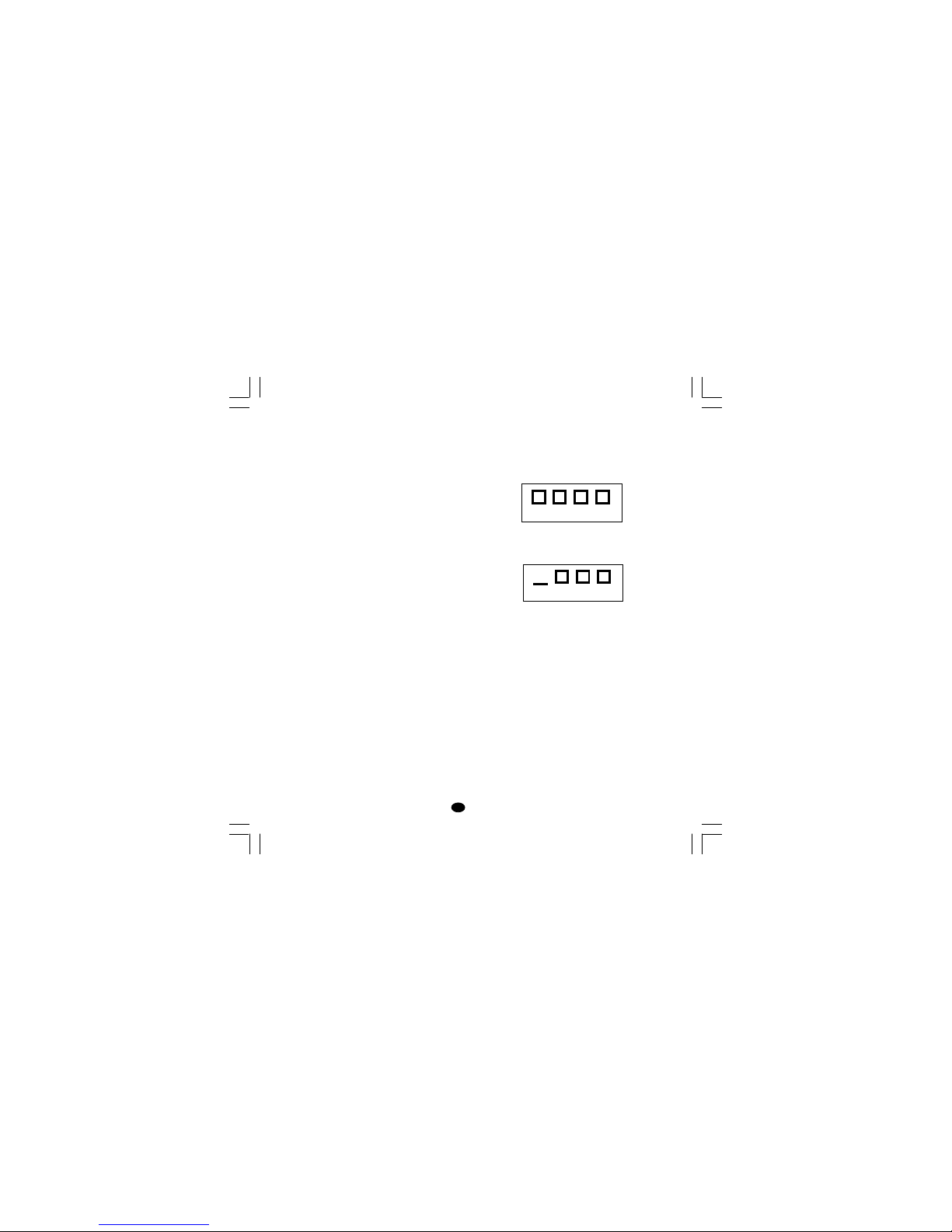
27
I
tOL Durata della limitazione della potenza
di uscita
Questo parametro non è disponibile
quando P5 = Sm.CL or Sm.OL
Campo: da 1 a 540 minuti. Oltre questo
valore il display indicherà "InF" e la
limitazione sarà sempre attiva.
Nota: tOL può essere modificato in
qualsiasi momento ma il nuovo valore
diventerà operativo solo alla successiva
accensione dello strumento.
rmP Massima velocità di variazione della
potenza di uscita
Questo parametro è disponibile solo se
Pb è diverso da 0.
Campo: da 0.1 a 25.0 %/s. Oltre questo
limite il display indicherà "InF" e la
limitazione sarà sempre esclusa.
F.CAL vedere il paragrafo "Calibrazione del
potenziometro di controreazione".
POS.L vedere il paragrafo "Calibrazione del
potenziometro di controreazione".
Fb.LC vedere il paragrafo "Calibrazione del
potenziometro di controreazione".
POS.H vedere il paragrafo "Calibrazione del
potenziometro di controreazione".
Fb.HC vedere il paragrafo "Calibrazione del
potenziometro di controreazione".
MESSAGGI DI ERRORE
INDICAZIONI DI FUORI CAMPO E/O
ROTTURE DEL SENSORE.
Questi strumenti sono in grado di rilevare il fuori
campo e la rottura del sensore.
Quando la variabile supera i limiti di campo
prefissati tramite il parametro P1, lo strumento
segnalerà la condizione di overrange
visualizzando sul display superiore l'indicazione
seguente.
Una condizione di UNDERRANGE (segnale
inferiore al valore di inizio scala) verrà
visualizzata con la seguente indicazione grafica:
Quando P41 è diverso da zero e viene rilevata
una condizione di fuori campo, lo strumento si
comporterà in funzione dell'impostazione dei
parametri P41 e P42.
Se P41 è uguale a 0, si verificherà una delle
seguenti condizioni:
- Se lo strumento è programmato per utilizzare
una sola uscita regolante ed ha rilevato una
condizione di OVERRANGE, l'uscita 1 viene
forzata a zero (per azione inversa) oppure a
100% (per azione diretta).
- Se lo strumento è programmato per utilizzare
due uscite regolanti ed ha rilevato una
condizione di OVERRANGE,
l'uscita 1 viene forzata a zero mentre l'uscita 3
viene forzata a 100%.
- Se lo strumento è programmato per utilizzare
una sola uscita regolante ed ha rilevato una
condizione di UNDERRANGE, l'uscita 1 viene
LFS-servo-4-02.p65 1/14/02, 3:47 PM27
Page 65

28
I
forzata a 100% (per azione inversa) oppure a
zero (per azione diretta).
- Se lo strumento è programmato per utilizzare
due uscite regolanti ed ha rilevato una
condizione di UNDERRANGE, l'uscita 1 viene
forzata a 100% mentre l'uscita 2 viene forzata a
zero.
Se P41 è uguale a 0 ed è stata configurata l'uscita
servomotore, si verificherà una delle seguenti
condizioni:
- Lo strumento ha rilevato un OVERRANGE ed al
servomotore è stata assegnata un' azione
inversa; OUT 1 (s) si porterà a OFF mentre
OUT 2 (t) si porterà a ON.
- Lo strumento ha rilevato un OVERRANGE ed al
servomotore è stata assegnata un' azione
diretta; OUT 1 (s) si porterà a ON mentre
OUT 2 (t) si porterà a OFF.
- Lo strumento ha rilevato un UNDERRANGE ed
al servomotore è stata assegnata un' azione
inversa; OUT 1 (s) si porterà a ON mentre
OUT 2 (t) si porterà a OFF.
- Lo strumento ha rilevato un UNDERRANGE ed
al servomotore è stata assegnata un' azione
diretta; OUT 1 (s) si porterà a OFF mentre
OUT 2 (t) si porterà a ON.
La rottura del sensore viene segnalata come
segue:
- ingresso TC/mV : OVERRANGE o
UNDERRANGE selezionabile tramite ponticello
- ingresso mA/V : UNDERRANGE
Nota: per gli ingressi lineari, è possibile rilevare la
rottura del sensore solo per gli ingressi 4-20 mA,
1-5 V o 2-10 V.
MESSAGGI DI ERRORE
Lo strumento è fornito di algoritmi di autodiagnostica.
Quando viene rilevato un errore, lo strumento
visualizza sul display inferiore la scritta "Err"
mentre sul display superiore viene visualizzato il
codice dell'errore rilevato.
LISTA DEGLI ERRORI POSSIBILI
SEr Errore nei parametri della seriale
100 Errore di scrittura delle EEPROM.
150 Errore generico nella CPU.
200 Tentativo di scrittura su memorie
protette
201 - 2xx Errore nei parametri di configurazio-
ne. Le due cifre meno significative
indicano il numero del parametro
errato (es. 209 Err indica errore del
parametro P9).
NOTA : Quando lo strumento rileva
un errore nei parametri di configurazione, è sufficiente ripetere la
configurazione del parametro
specifico.
299 Errore sulla selezione dell'uscita rego-
lante
301 Errore di calibrazione dell'ingresso
selezionato
302 Errore nella calibrazione del
potenziometro di controreazione
NOTA: Se viene rilevato l'errore
302, premere contemporaneamente
i pulsanti s e t per caricare i
parametri predefiniti relativi al
potenziometro di controreazione;
poi ripetere la calibrazione del
potenziometro.
307 Errore di calibrazione ingresso RJ
400 Errore nei parametri di controllo
LFS-servo-4-02.p65 1/14/02, 3:47 PM28
Page 66

29
I
NOTA
Se viene rilevato l'errore 400,
premere contemporaneamente i
pulsanti s e t per caricare i
parametri predefiniti; poi ripetere
l'impostazione dei parametri di
controllo.
500 Errore di Auto-zero
502 Errore di RJ
501 Errore dell'integratore di zero
510 Errore durante la procedura di
calibrazione.
512 Errore durante la calibrazione del
potenziometro di controreazione.
NOTA Per tutti gli altri errori contattare il fornitore.
LFS-servo-4-02.p65 1/14/02, 3:47 PM29
Page 67

30
I
CARATTERISTICHE TECNICHE
SPECIFICHE TECNICHE
Custodia: PC di colore grigio; grado di auto-
estinguenza: V-0 secondo UL 94.
Protezione frontale- Il prodotto è stato progettato e
verificato per garantire una protezione IP 65 (*) e
NEMA 4X per uso in luogo coperto.
(* le verifiche sono state eseguite in accordo gli
standard CEI 70-1 e NEMA 250-1991.
Installazione: Montaggio a pannello
Morsettiera posteriore: 15 terminali a vite (vite
M3 per cavi da φ 0.25 a φ 2.5 mm
2
o da AWG 22 a
AWG 14 ) con diagrammi di collegamento e copri
morsettiera di sicurezza.
Dimensioni: secondo DIN 43700 48 x 48 mm,
profondità 122 mm.
Peso: 250 g.
Alimentazione:
- da 100V a 240V c.a. 50/60Hz (-15% a + 10% del
valore nominale).
Autoconsumo: 6 W max.
Resistenza di isolamento: > 100 MΩ secondo
EN 61010-1.
Rigidità dielettrica: 2300 Vrms secondo
EN61010-1
Tempo di aggiornamento del visualizzatore:
500 ms.
Intervallo di campionamento:
- 250 ms per ingressi lineari
- 500 ms per ingresso da TC.
Precisione:
+ 0,2% v.f.s. + 1 digit @ 25 °C di
temperatura ambiente.
Reiezione di modo comune: 120 dB a 50/60 Hz.
Reiezione di modo normale: 60 dB a 50/60 Hz.
Compatibilità elettromagnetica e normative di
sicurezza: Questo strumento è marcato CE e per-
tanto è conforme alle direttive 89/336/EEC (standard
armonizzato di riferimento EN-50081-2 e EN-50082-
2) ed alle direttive 73/23/EEC e 93/68/EEC (standard
armonizzato di riferimento EN 61010-1)
Categoria di installazione: II
Livello di inquinamento: 2
Deriva termica: (CJ esclusa)
< 200 ppm/°C dell'ampiezza del campo per ingressi
mV e TC campi 1, 3, 5, 7 , 21, 22, 23, 25.
< 300 ppm/°C dell'ampiezza del campo per
ingressi mA/V
< 400 ppm/°C dell'ampiezza del campo per
ingressio TC campi 0, 2, 4, 6, 24.
< 500 ppm/°C dell'ampiezza del campo per
ingressio TC campi 8, 9, 26, 27.
< 800 ppm/°C dell'ampiezza del campo per
ingresso TC campi 10,28.
Temperatura di funzionamento: da 0 a 50 °C.
Temperatura di immagazzinamento: -20 a +70 °C
Umidità: da 20 % a 85% RH, senza condensa.
Protezioni:
1) WATCH DOG circuito per il restart automatico.
2) DIP SWITCH per la protezione dei parametri di
calibrazione.
INGRESSI
A) TERMOCOPPIE
Tipo: L -J -K -T -N -R -S- B. °C/°F selezionabile.
Resistenza esterna: max. 100 Ω, con errore
massimo pari a 0,1% dell'ampiezza del campo
selezionato
Burn out: segnalata come condizione di
overrange (standard). Tramite ponticelli è
possibile selezionare la condizione di underrange.
Giunto freddo: compensazione automatica da 0
a 50 °C.
Precisione giunto freddo: 0.1 °C/°C
Impedenza di ingresso: > 1 MΩ
Calibrazione: secondo IEC584-1 e DIN43710 -
1977
LFS-servo-4-02.p65 1/14/02, 3:47 PM30
Page 68
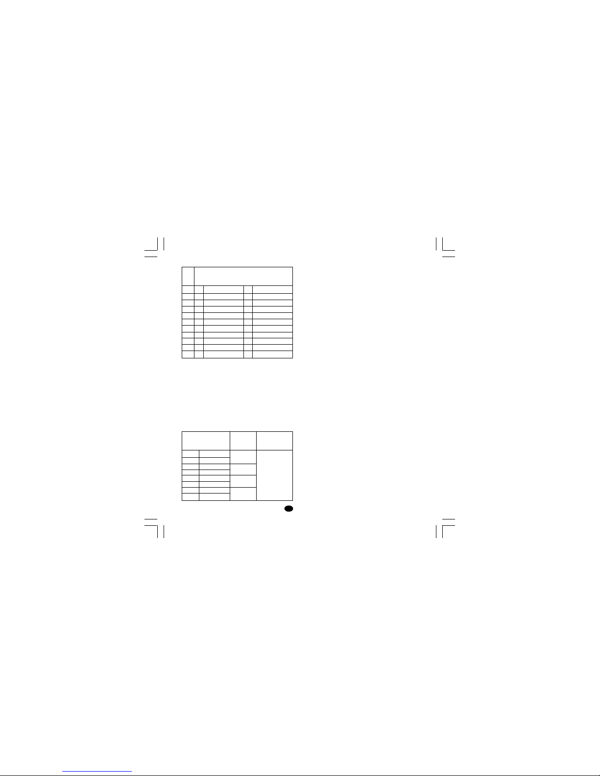
31
I
C) Ingressi lineari
Visualizzazione: programmabile da -1999 a +4000
Punto decimale: programmabile in ogni posizione.
Burn out: Lo strumento visualizza le condizioni di
burn-out come una condizione di underrange per le
portate 4-20 mA, 1-5 V e 2-10 V.
Lo strumento visualizza le condizioni di burn-out
come una condizioni di overrange per le portate 060 mV, 12-60 mV.
Nessuna indicazione è prevista per le portate 0-20
mA, 0-5 V e 0-10 V.
D) INGRESSO POTENZIOMETRICO DI
CONTROREAZIONE
Tipo di potenziometro: da 100 Ω a 1 kΩ.
E) INGRESSI LOGICI
Lo strumento è provvisto di 2 ingressi logici.
L'ingresso logico 1 è utilizzato per selezionare il
set point operativo.
La funzionalità dell'ingresso logico 2 viene
programmata tramite il parametro P24.
NOTE
1) Le opzioni "interfaccia seriale" e "ingressi logici"
sono mutuamente esclusive e possono essere
selezionate tramite ponticelli.
2) Utilizzare contatti esterni con portata migliore di
0.5 mA, 5 V DC.
3) Lo strumento abbisogna 100 ms per riconoscere la variazione di stato del contatto.
4) Gli ingressi logici sono isolati rispetto all'ingresso di misura.
SET POINT
Questo strumento consente di utilizzare 2 set point
(SP, SP2).
La selezione del set point operativo può essere
eseguita solo tramite l'ingresso logico 1.
Passaggio tra set point:
Il passaggio da un set point ad un'altro (o tra due
differenti valori dello stesso set point) può
avvenire a gradino o tramite due differenti rampe
(rampa per valori crescenti o decrescenti).
Velocità di variazione: da 1 a 100 unità/minuto.
Limitatori del set point: parametri RLO e RHI .
T/C
tipo
L
L
J
J
K
K
T
N
R
S
B
Scale
0
1
2
3
4
5
6
7
8
9
10
0/ +400.0°C
0 / + 900°C
-100.0/ +400.0°C
-100/ + 1000°C
-100.0/ +400.0°C
-100/ + 1370°C
-199.9/ +400.0°C
-100/ + 1400°C
0 / + 1760°C
0 / + 1760°C
0 / +1820 °C
21
22
23
24
25
26
27
28
---
0 / + 1650 °F
---
-150/ + 1830 °F
---
-150/ + 2500 °F
-330/ + 750 °F
-150/ + 2550 °F
0 / + 3200 °F
0 / + 3200 °F
0 / + 3310 °F
Tipo di ingresso
13
14
15
16
17
18
19
20
0 - 60 mV
12 - 60 mV
0 - 20 mA
4 - 20 mA
0 - 5 V
1 - 5 V
0 - 10 V
2 - 10 V
impedenza
> 1 MΩ
< 5 Ω
> 400 kΩ
> 400 kΩ
precisione
0.2 % + 1 digit
@ 25°C
LFS-servo-4-02.p65 1/14/02, 3:47 PM31
Page 69

32
I
AZIONI DI CONTROLLO
Azione regolante: PID o SMART
Tipo: uno (riscaldamento o raffreddamento) o due
(riscaldamento e raffreddamento) uscite regolanti.
Banda proporzionale (Pb): da 1.0 a 200.0 % del
campo di ingresso.
Se Pb=0, l'azione di controllo diventa ON/OFF.
Isteresi (per controllo ON/OFF): da 0.1 % a 10.0
% dell'ampiezza del campo di ingresso.
Tempo integrale: da 10'' a 20' oppure escluso.
Tempo derivativa: da 1'' a 10' oppure esclusa.
Precarica dell'integrale:
- da 0 a 100 % per un'uscita regolante.
- da -100 a 100% per due uscite regolanti .
Funzione SMART: abilitabile/disabilitabile da
tastiera.
Modo Auto/Manuale: selezionabile da tastiera.
Passaggio Auto/Manuale: senza scosse
Indicatore "MAN": spento in modo auto, acceso
in modo manuale.
USCITE
Questo strumento è equipaggiato con quattro
uscite a relè.
L'uscita 1 può essere usata come uscita per
servomotore (insieme all'uscita 2, i 2 relè sono
interbloccati), oppure può essere usata come
uscita a relè indipendente (in questo caso l'uscita
2 non può essere utilizzata); le uscite 3 e 4 sono
uscite indipendenti (l'uscita 4 è opzionale).
Le uscite possono essere programmate come
segue:
Out 1 + Out 2 Out 3 OUT 4
interbloccati relè relè
servomotore AL1 AL2+ AL3
riscaldamento AL1 AL2+ AL3
raffreddamento AL1 AL2+ AL3
riscaldamento raffreddam. AL2+ AL3
NOTA: gli allarmi 2 e 3 sono in OR sull'uscita 4.
Tempo di aggiornamento dell'uscita regolante:
- 250 ms se è stato selezionato un ingresso lineare
- 500 ms se è stato selezionato un ingresso da TC
Risoluzione dell'uscita: 0.1%.
Azione: diretta o inversa programmabile.
Indicazione del livello di uscita
Lo strumento indica separatamente i valori delle
uscite di riscaldamento e raffreddamento.
Limitazione della potenza di uscita
- Per una uscita regolante: da 0.0 a 100.0 % .
- per due uscite regolanti: da -100.0% a +100.0%
Questa funzione può attivarsi automaticamente all'accensione dello strumento e rimanere attiva per un
tempo programmato (onde evitare shock termici o
produrre il preriscaldamento dell'impianto).
LFS-servo-4-02.p65 1/14/02, 3:47 PM32
Page 70

33
I
Uscite a relè
Uscite 1 e 2: due relè interbloccati; contatto SPST
con portata 3 A a 250 V c.a. su carico resistivo
(contatto NO).
Uscita 3: contatto SPST con portata 2 A a 250 V
c.a. su carico resistivo (contatto NO).
Uscita 4: contatto SPST con portata 2 A a 250 V
c.a. su carico resistivo (contatto NO).
NOTE: il lato C delle uscite 3 e 4 è in comune.
Indicatori dello stato delle uscite: 4 indicatori
(s, t, OUT 3 e OUT 4) si accendono quando
la rispettiva uscita è in condizione ON
ALLARMI
Azione: diretta o inversa programmabile
Funzione dell'allarme: ogni allarme può essere
programmato come allarme di processo, di banda
o di deviazione.
Riarmo degli allarmi: automatico o manuale
programmabile singolarmente.
Mascheratura allarme: Ogni allarme può essere
programmato come allarme con o senza
mascheratura.
Questa funzione consente di evitare false
indicazioni di allarme all'accensione o dopo una
modifica del set point.
Allarmi di processo:
Modo operativo: di massima o di minima.
Soglia: programmabile in unità ingegneristiche al-
l'interno del campo di ingresso (P3 - P2).
Isteresi: programmabile da 0.1 % a 10.0 %
dell'ampiezza del campo di ingresso.
Allarme di banda
Modo operativo: dentro o fuori banda.
Soglia: programmabile da 0 a 500 unità.
Isteresi: programmabile da 0.1 % a 10.0 %
dell'ampiezza del campo di ingresso.
Allarmi di deviazione
Modo operativo: sotto o sopra il valore program-
mato.
Soglia: programmabile da - 500 a +500 unità.
Isteresi: programmabile da 0.1 % a 10.0 %
dell'ampiezza del campo di ingresso.
INTERFACCIA DI COMUNICAZIONE SERIALE
Tipo: RS-485
Protocolli: MODBUS, JBUS, ERO polling/
selecting.
Velocità di comunicazione: programmabile da
600 a 19200 BAUD.
Formato: 7 o 8 bit programmabile.
Parità: pari, dispari o nessuna.
Bit di stop: uno.
Indirizzi:
- da 1 a 95 per il protocollo ERO.
- da 1 a 255 per gli altri protocolli
Livelli di uscita: secondo standard EIA.
NOTA: Le opzioni "interfaccia seriale" e "ingressi
logici" sono mutuamente esclusive e possono
essere selezionate tramite ponticelli.
LFS-servo-4-02.p65 1/14/02, 3:47 PM33
Page 71

34
I
MANUTENZIUONE
1) TOGLIERE TENSIONE ALL'APPARECCHIO
(alimentazione, uscite a relè, ecc),
2) Sfilare lo strumento dalla custodia
3) Facendo uso di un aspiratore o un getto di aria
compressa a bassa pressione (max. 3 kg/cm
2
)
rimuovere eventuali depositi di polvere e
sporcizia dalle ferritoie di ventilazione e dai
circuiti facendo attenzione a non danneggiare i
componenti.
4) Per pulire le parti esterne in plastica o gomma
usare solamente uno straccio pulito ed
inumidito con:
- alcool etilico (puro o denaturato) [C
2H5
OH]
-alcool isopropilico (puro o denaturato)
[(CH3)2CHOH]
- Acqua (H2O)
5) Controllare che non vi siano morsetti allentati
6) Prima di reinserire lo strumento nella sua custodia assicurarsi che l'apparecchio sia perfettamente asciutto.
7) Reinserire l'apparecchio e ridare tensione.
LFS-servo-4-02.p65 1/14/02, 3:47 PM34
Page 72

Appendix A.1
APPENDIX A
DEFAULT PARAMETERS
DEFAULT OPERATIVE PARAMETERS
The control parameters can be loaded with
predetermined default values. These data are the
typical values loaded in the instrument prior to
shipment from factory. To load the default values
proceed as follows:
a) The instrument must be in "UNLOCK" condition
b) The SMART function is disabled.
c) The upper display will show the process
variable while the lower display will show the
set point value.
d) Held down t pushbutton and press s
pushbutton; the display will show:
e) Press s or t pushbutton; the display will show:
g) Press FUNC pushbutton; the display will show:
This means that the loading procedure has been
initiated. After about 3 seconds the loading
procedure is terminated and the instrument
reverts to NORMAL DISPLAY mode.
The following is a list of the default operative
parame-ters loaded during the above procedure:
PARAMETER DEFAULT VALUE
SP = minimum range-value
Snrt = Disable
m.rSt = OFF
SP2 = minimum range value
nnn = OFF
A1 A2 A3 = minimum range value for
process alarms
0 for deviation or band alarms
HSA1 HSA2 HSA3 = 1
PB = 1.5 %
hyS = 0.5 %
ti = 2.00 (2 minutes)
td = 0.10 (10 seconds)
IP = 50 % for servomotor control drive
30 % for one time proportional
control output
0 % for two control outputs.
Sm.tt = 0.25 (seconds)
Sm.db = 5 (%)
Sm. LL = 0 (%)
Sm.HL = 100 (%)
Cy1 = 15 (seconds)
When two control outputs are
configured and the OUT1 has a
"dir" action, the CY1 default
value will be equal to:
10 seconds for P25 = AIr
4 seconds for P25 = OIL
2 seconds for P25 = H2O
Cy3 = 15 (seconds)
When two control outputs are
configured and the OUT3 has a
"dir" action, the CY3 default
value will be equal to:
10 seconds for P25 = AIr
4 seconds for P25 = OIL
2 seconds for P25 = H2O
OFFOFF
OFFOFF
OFF
dFLt dFLt
dFLt dFLt
dFLt
ONON
ONON
ON
dFLtdFLt
dFLtdFLt
dFLt
LOAdLOAd
LOAdLOAd
LOAd
LFS-servo-Z-01.p65 1/14/02, 3:49 PM1
Page 73

Appendix A.2
rC = 1.00 for P25 = AIr
0.80 for P25 = OIL
0.40 for P25 = H2O
OLAP =0
rL = initial scale value
rH = 1250 when P1 = 5, 8 or 9 and
the full scale value is > 1250;
the full scale value in all other
cases
Gr.A1 = 4 digit per minute
CH.Gr = 1250 when P1 = 5, 8 or 9 and
the full scale value is > 1250;
the full scale value in all other
cases
Gr.A2 = Infinite
Gr.b1 = 4 digit per minute
Gr.b2 = Infinite
OLH = 100 %
tOL = infinite
rnP = 25 % /s
DEFAULT CONFIGURATION
PARAMETERS
The configuration parameters can be loaded with
predetermined default values. These data are the
typical values loaded in the instrument prior to
shipment from factory. To load the default values
proceed as follows:
a) The upper display will show:
b) Mantaining the pressure on the t pushbutton
push the s pushbutton also.
The instrument will show
c) Press s pushbutton to select between table 1
(european) or table 2 (american) default set of
parameters; the display will show:
d) Press FUNC pushbutton; the display will show:
This means that the loading procedure has been
initiated.
After about 3 seconds the loading procedure is
terminated and the instrument reverts to display
"COnF".
COnFCOnF
COnFCOnF
COnF
OFFOFF
OFFOFF
OFF
dFLtdFLt
dFLtdFLt
dFLt
tb. 1tb.1
tb. 1tb.1
tb. 1
dFLtdFLt
dFLtdFLt
dFLt
LOAdLOAd
LOAdLOAd
LOAd
LFS-servo-Z-01.p65 1/14/02, 3:49 PM2
Page 74

Appendix A.3
PARA. TABLE 1 TABLE 2
SEr 1 ErO ERO
SEr 21 1
SEr 3 4800 4800
SEr 48 8
P1 9 23
P2 ----. ----.
P3 0 0
P4 1760 2190
P5 SnOL SnOL
P6 Fb Fb
P7 AL1.d AL1.d
P8 H.A. H.A.
P9 nonE nonE
P10 H.A. H.A.
P11 AL3.P AL3.P
P12 H.A. H.A.
P13 COnF COnF
P14 1200 1380
P15 850 1560
P16 1 1
P17 0 0
P18 0 0
P19 dis dis
P20 dis dis
P21 Enb Enb
P22 rEv rEv
P23 1000 1000
P24 nOnE nOnE
P25 Air Air
P26 dir dir
P27 OFF OFF
P28 dir dir
P29 OFF OFF
P30 OFF OFF
P31 0 0
P32 On On
P33 0 0
P34 30.030.0
P35 1.01.0
P36 00.20 00.20
P37 OFF OFF
P38 On On
P39 3 3
P40 bUnP bUnP
P41 5 5
P42 0 0
P43 nOFL. nOFL.
P44 P.I.d. P.I.d.
P45 1 1
P46 Tm.10 tm.30
P47 0 0
P48 OP.SP OP.SP
P49 10 10
P50 0 0
P51 0 0
LFS-servo-Z-01.p65 1/14/02, 3:49 PM3
Page 75

Appendix A.4
SECURITY CODES
In this page it is possible to fill out the configuration and the
run time security codes of the instrument.
Tag name
Tag number
Run time security code
Configuration security code
Master key (Passe-partout code)
LFS- Servo
If it is desired to keep the codes secret, cut this page along the
dotted line.
LFS-servo-Z-01.p65 1/14/02, 3:49 PM4
Page 76

divisione di EUROTHERM S.r.ldivisione di EUROTHERM S.r.l
divisione di EUROTHERM S.r.ldivisione di EUROTHERM S.r.l
divisione di EUROTHERM S.r.l
Via E. Mattei, 21
28100 Novara
Italy
Tel. +39 0321481111
Fax +39 0321481112
E-mail [email protected]
Http://www.eroelectronic.com
XKS-A-B0.pmd 15/09/2005, 9.096
 Loading...