

Page 1
EROAD Ehubo®
Installation Guide
Page 2

© 2018 EROAD. Doc MN000860A-G
MANUAL,EROAD,EBOX2,INSTALLATION,US,ELD,VER2.
By using this Ehubo you are agreeing to be bound by EROAD’s
Terms of Use that can be located at www.eroad.com/us/terms.
Page 3

Contents
1 Introduction 2
2 Legal Notices 4
2.1 Legal Notice and Disclaimer 4
2.2 Google Protocol Buer Software License 5
2.3 Trademarks 5
3 Important Safety Information 6
3.1 Personal Protective Equipment 6
3.2 Installation 6
3.3 Operation 7
3.4 FCC Compliance 7
3.5 Replaceable Batteries 7
4 Parts List and Documentation 8
4.1 Option 1: RAM Suction Cup Mounting Kit 9
4.2 Option 2: Permanent Mount/Tape Mntg Kit 9
4.3 Ehubo Hardware Installation Kit
(non ECM & OBD-II)
5 Mounting the Ehubo 10
6 Standard Installation (with ECM Connection) 12
6.1 Hardware 12
6.2 Running the Install Wizard (w/ECM) 14
6.3 Troubleshooting ECM Installations 19
7 Non-Standard Installation (without ECM
Connection)
7.1 Hardware 20
7.2 Running the Install Wizard (non ECM) 22
7.3 Troubleshooting Non-ECM Installations 26
8 OBD-II Installation 27
8.1 Hardware 27
8.2 Running the Install Wizard (OBD-II) 29
20
9
8.3 Troubleshooting OBD-II Installations 33
9 Replacement Installation 34
10 Appendix 36
Page 4

2
1. Introduction
IMPORTANT: DO NOT INSTALL OR USE THE EROAD HARDWARE
UNTIL YOU HAVE READ THIS INSTALLATION GUIDE THOROUGHLY.
Congratulations on choosing EROAD. This device is an
FMCSA-compliant electronic logging device (ELD), in addition
to an Oregon Department of Transportation (ODOT)-approved
electronic Weight-Mile Tax collection device. The EROAD
technology platform also oers a complete suite of user-friendly
compliance and telematics assets, including automated IFTA,
safety, and fleet management reporting.
The EROAD in-vehicle device is referred to as the Ehubo in the
remainder of this guide, which is the name of our in-vehicle
hardware.
EROAD recommends the use of a professional automotive
technician to install the Ehubo in your vehicle. Please make this
guide available to your installer and keep it for future reference.
The Ehubo is easy to install by carrying out the following steps as
described in this guide:
1. Make sure to read the Safety Information section, familiarize
yourself with the local laws regarding the installation and
use of the Ehubo, and use and follow all standard safety
precautions.
2. Choose a suitable mounting location and mount the Ehubo.
3. Install the Ehubo by connecting it to the vehicle.
4. Complete the installation by following the Ehubo’s onscreen guide.
Keep this manual, because you will need these instructions when:
• Replacing or moving an Ehubo unit
• Rerunning the installation wizard (1) if moving the unit, (2)
if the unit loses connection to the ECM and a diagnostic
code appears, (3) or if requested by a technical support
representative
• Ordering replacement parts
CAUTION:
THERE IS A RISK OF EXPLOSION IF THE
BATTERY IS REPLACED BY AN INCORRECT TYPE.
DISPOSE OF USED BATTERIES ACCORDING TO THE INSTRUCTIONS.
See Chapter 3 for more information.
Refer to Replacement Installation on page 36 if you are
installing a replacement Ehubo.
Page 5

REVISION HISTORY
The document changes are outlined below.
Date Ver. No. Description
Jan. 2018 2 • Intro: Revised, added safety
precaution
• Updated legal notice, trademarks
• Ch. 3: Added Replaceable battery
guidelines and precaution
• Ch. 4: Added mounting kits
• Ch. 5: Added mounting instructions
• Ch. 6: Added Install Wizard
instructions and troubleshooting
• Ch. 7: Added Install Wizard
Instructions and troubleshooting
• Ch. 8: New OBD-II instructions
• Appendix: Added pin diagrams for
troubleshooting
• Includes contents from service
bulletins TSB-Ehubo-2017-1,
TSB-Ehubo-2017-2, and TSBEhubo-2017-3
3
Feb 2019 2.1d • Updated FCC Statement
ABBREVIATIONS
The following acronyms and abbreviations are used throughout
this installation guide. They are defined on their first appearance
and then abbreviated.
Abbreviation Description
ABS Anti-lock braking system
ACC Accessory
EBS Electronic braking system
ECM Electronic control module
Ehubo EROAD’s in-vehicle device (may be configured
as an ELD)
ELD Electronic logging device
FCC Federal Communications Commission
FMCSA Federal Motor Carrier Safety Administration
GPS Global positioning system
IFTA International Fuel Tax Agreement
IGN Ignition
LED Light emitting diode
Nyloc Nylon-insert lock nut
ODOT Oregon Department of Transportation
PPE Personal protective equipment
Page 6

4
2. Legal Notices
Please read carefully before beginning installation!
2.1 LEGAL NOTICE AND DISCLAIMER
The legislation and rules concerning the installation and operation
of GPS driver aids and messaging devices such as the Ehubo vary
from each country and state. Please familiarize yourself with the
laws of the jurisdiction(s) in which the vehicle will be operated in
prior to installing and using the Ehubo.
Driving laws place the responsibility on the driver to correctly
install and use GPS driver aids. It is, therefore, the Customer’s
sole responsibility to install and use the Ehubo in a manner that
complies with the law and will not cause accidents, personal
injury or property damage. The owner of this Ehubo is solely
responsible for observing safe driving practices.
EROAD DISCLAIMS ALL LIABILITY FOR ANY USE OF THIS
EHUBO IN A WAY THAT MAY CAUSE ACCIDENTS, DAMAGE
OR VIOLATE THE LAW.
TO THE MAXIMUM EXTENT PERMITTED BY LAW,
ALL REPRESENTATIONS AND WARRANTIES (EXCEPT
ANY WHICH MAY NOT LAWFULLY BE EXCLUDED) ARE
EXPRESSLY EXCLUDED, INCLUDING WITHOUT PREJUDICE
TO THE GENERALITY OF THE FOREGOING, THE IMPLIED
WARRANTIES OF MERCHANTABILITY AND FITNESS FOR
A PARTICULAR PURPOSE.
As EROAD is continuously improving its products, EROAD may
make changes to the Ehubo at any time, which may not be
reflected in this document. Please contact your nearest EROAD
oce if you require any further assistance.
If you think that installation of EROAD’s in-vehicle hardware
or any accessories associated with EROAD’s system may have
caused your vehicle’s performance to be impeded, please contact
EROAD Technical Support at 1-855-503-7623 immediately to
resolve the issue. EROAD is not liable for any costs or expenses
incurred by engaging a third party to repair the fault without
EROAD’s prior consent.
2.2 GOOGLE PROTOCOL BUFFER SOFTWARE LICENSE
Copyright 2008, Google Inc.
All rights reserved.
Redistribution and use in source and binary forms, with or
without modification, are permitted provided that the following
conditions are met:
• Redistributions of source code must retain the above
copyright notice, this list of conditions and the following
disclaimer.
• Redistributions in binary form must reproduce the
above copyright notice, this list of conditions and the
followingdisclaimer in the documentation and/or other
materials provided with the distribution.
Page 7

• Neither the name of Google Inc. nor the names of its
contributors may be used to endorse or promote products
derived from this software without specific prior written
permission.
THIS SOFTWARE IS PROVIDED BY THE COPYRIGHT HOLDERS
AND CONTRIBUTORS “AS IS” AND ANY EXPRESS OR IMPLIED
WARRANTIES, INCLUDING, BUT NOT LIMITED TO, THE IMPLIED
WARRANTIES OF MERCHANTABILITY AND FITNESS FOR
A PARTICULAR PURPOSE ARE DISCLAIMED. IN NO EVENT
SHALL THE COPYRIGHT OWNER OR CONTRIBUTORS BE
LIABLE FOR ANY DIRECT, INDIRECT, INCIDENTAL, SPECIAL,
EXEMPLARY, OR CONSEQUENTIAL DAMAGES (INCLUDING,
BUT NOT LIMITED TO, PROCUREMENT OF SUBSTITUTE GOODS
OR SERVICES; LOSS OF USE, DATA, OR PROFITS; OR BUSINESS
INTERRUPTION) HOWEVER CAUSED AND ON ANY THEORY
OF LIABILITY, WHETHER IN CONTRACT, STRICT LIABILITY, OR
TORT (INCLUDING NEGLIGENCE OR OTHERWISE) ARISING
IN ANY WAY OUT OF THE USE OF THIS SOFTWARE, EVEN IF
ADVISED OF THE POSSIBILITY OF SUCH DAMAGE.
Code generated by the Protocol Buer compiler is owned by
the owner of the input file used when generating it. This code is
not standalone and requires a support library to be linked with
it. This support library is itself covered by the above license
5
2.3 TRADEMARKS
Bluetooth® is a registered trademark of Bluetooth SIG, Inc., and
its aliates. Any other company names, product names, service
names and logos are the trademarks of their respective owners.
RAM® and RAM Mount are either registered trademarks or
trademarks of National Products Inc., in the United States and/
or other companies.
3. Important Safety Information
3.1 PERSONAL PROTECTIVE EQUIPMENT
Federal, national or local health, and safety regulations may
require wearing appropriate Personal Protective Equipment
(PPE). PPE may include items such as safety glasses, safety
shoes, work gloves, hard hat, high visibility vest, and work
uniform. Make sure to comply with appropriate standards, and
check with customers or third parties to verify whether they have
additional PPE requirements.
3.2 INSTALLATION
• Installers and contractors must follow all health and safety
regulatory requirements to ensure a safe and healthy work
environment.
• Set the parking brake whenever the equipment is parked.
Equipment parked on inclines shall have the wheels chocked
and the parking brake set.
• Equipment, or parts thereof, which are suspended or held
aloft by use of slings, hoists, or jacks shall be substantially
blocked or cribbed to prevent falling or shifting before
employees are permitted to work under or between them.
• Installing and servicing electronic devices can be hazardous due
Page 8

6
to electrical components. Make sure to create a safe working
environment to avoid hazards and to ensure correct and safe
installation and operation.
• EROAD recommends the use of a qualified professional automotive
technician to install the Ehubo. Make this Installation Guide available
to the appropriate personnel. Store it for future reference.
• Do not run cables close to heat sources, sharp edges or other
obstacles that might damage them.
• Do not run cables directly next to safety-relevant devices.
• Place all wiring under the dash to avoid creating a hazard.
• Do not damage existing wiring and components when drilling the
dashboard.
• Some countries and states prohibit the installation of global
positioning system (GPS) driver aids on windshields. Some areas
might allow installation of the Ehubo on the windshield. It should
be positioned as low as possible and closest to the driver door to
minimize obstruction of the driver’s field of view.
• Avoid fitting the Ehubo in a location that could cause injury to a
driver or passenger in a crash. This includes potential head strike
zones on the windshield or dashboard, or other locations where a
deploying airbag may contact the Ehubo.
• Do not block or impair the deployment of airbags and other safetyrelevant devices.
• Avoid placing the Ehubo where it may impede or limit the driver’s
movement when driving or exiting the vehicle (including in an
accident).
• Check that all safety-relevant equipment is working properly after
installation.
3.3 OPERATION
• Familiarize yourself with local laws concerning the use of GPS
driver aids. Some countries and states prohibit drivers from viewing
screens or making or receiving text messages while driving a vehicle.
• The Ehubo screen is initially configured to automatically turn o
when movement is detected to avoid driver distraction.
• Minimize the amount of time spent viewing the screen if the Ehubo
screen has been activated to turn on during driving.
• Only operate or look at the Ehubo when it is safe to do so. Do not
message, change settings or access functions while driving. Pull over
before you wish to attempt such activities. Always keep your hands
free to operate the vehicle while driving. Your first consideration
while driving should be road safety.
• The screen display of the speed limit or the vehicle’s speed is for
information only. Please ensure that you observe all posted speed
limits and drive to the conditions.
• Do not use sharp-edged objects on the Ehubo touch screen.
• The Ehubo is not waterproof. Do not spill any liquid on it.
• Protect the Ehubo from extreme temperatures. Operating
temperature for the Ehubo is between -20°C/-4°F and 85°C/185°F.
• Always follow local regulations when disposing of the Ehubo.
• Do not dispose of the battery in trash cans, fire or water.
Page 9

3.4 FCC COMPLIANCE STATEMENT
This device complies with part 15 of the Federal Communications
Commission (FCC) Rules. Operation is subject to the following two
conditions: (1) this device may not cause harmful interference, and
(2) this device must accept any interference received, including
interference that may cause undesired operation. This device has
been tested and found to comply with the limits for a Class B digital
device, pursuant to Part 15 of the FCC Rules. These limits are designed
to provide reasonable protection against harmful interference in a
residential installation. This equipment generates, uses and can radiate
radio frequency energy and, if not installed and used in accordance
with the instructions, may cause harmful interference to radio
communications. However, there is no guarantee that interference
will not occur in a particular installation. If this equipment does
cause harmful interference to radio or television reception, which
can be determined by turning the equipment o and on, the user is
encouraged to try to correct the interference by one or more of the
following measures:
• Reorient or relocate the receiving antenna.
• Increase the separation between the equipment and receiver.
• Connect the equipment into an outlet on a circuit dierent from that to
which the receiver is connected.
• Consult the dealer or an experienced radio/TV technician for help.
Responsible Party - U.S. Contact Information
Company Name: EROAD, Inc.
Address: 7618 S.W. Mohawk Street, Tualatin, OR 97062
Contact Information: 1-855-503-7623
7
Changes or modifications not expressly approved by the party responsible
for compliance could void the user's authority to operate the equipment.
RF Exposure Information
This device complies with FCC radiation exposure limits set forth for an
uncontrolled environment. In order to avoid the possibility of exceeding
the FCC radio frequency exposure limits, human proximity to the antenna
shall not be less than 20cm (8 inches) during normal operation.
Viewing Regulatory and Compliance Information
Hold down the EROAD logo in the upper left corner until the Options
menu appears, and then tap the Regulatory button.
3.5 REPLACEABLE BATTERIES
Newer devices use rechargeable batteries, but older devices use
replaceable batteries. Do not replace a rechargeable battery with a
replaceable battery. If you replace a battery with an incorrect type
and it could result in an explosion (such as some lithium batteries), the
following applies:
• if the battery is placed in an OPERATOR ACCESS AREA, add a
marking close to the battery or a statement in both the operating
and the servicing instructions, or
• if the battery is placed elsewhere in the equipment, add a marking
close to the battery or a statement in the servicing instructions , as
follows:
CAUTION: RISK OF EXPLOSION IF BATTERY IS REPLACED BY AN INCORRECT
TYPE. DISPOSE OF USED BATTERIES ACCORDING TO THE INSTRUCTIONS.
Page 10
8
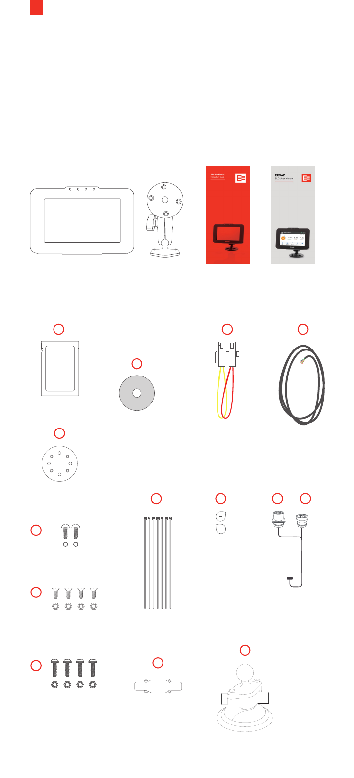
4. Parts List and Documentation
Your Ehubo box contains the parts and documentation for the
mounting option that you selected. Not all of the following
parts are included in your box. Individual parts included in each
mounting kit are described in the tables shown on the right.
NOTE: Place the EROAD ELD User Manual and visor cards in the
truck cab per the ELD mandate.
EROAD
ELD User Manual
EROAD Ehubo
(Pre-fitted Extendable Cable)
Mounting
Arm
Installation
Guide
+ visor cards,
if applicable
A
TECHNICAL CLEANING WIPE
Alcohol wipe
B
Mounting plate
F
2 x ¾”/ 19 mm
screws + washers
G
4 x ½”/ 13 mm
counter sunk screws
+ nyloc nuts
H
C
High–strength
adhesive tape
(optional, for
tape mount)
I
Cable ties
J
D
Fuse kit
(not included w/ELD)
(permanent/
switched power)
K
Rear hatch
security plugs
(not included)
included with cable
M
E
Wiring Harness
(not included
w/ELD)
L1 L2
ECM Y-cable -
kit (model year
2000 or newer)
4 x 1”/ 25 mm
screws + nuts
Screws, nuts and washers
to mount Ehubo
Cable
clamp
RAM Suction Cup
Page 11
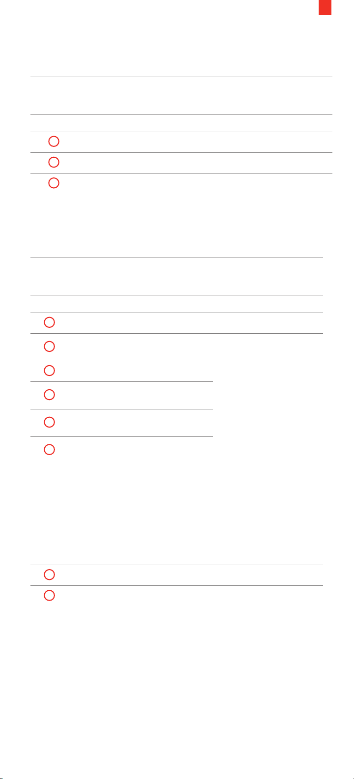
4.1 OPTION 1: RAM SUCTION CUP MOUNTING KIT
Code Item Name Part Number
RAM Suction Cup
Mounting Kit (with all
HR000900A-G
parts listed below)
Mounting arm MS000806-G
9
M
F
A
RAM suction cup MS000803-G
2 x 1/4” / 19mm screws
Alcohol wipe
4.2 OPTION 2: PERMANENT MOUNT/TAPE MOUNTING KIT
Code Item Name Part Number
Permanent Mount / Tape
Mounting Kit (with all
HR000901A-G
parts listed below)
Mounting arm MS000806-G
A
C
B
H
G
Alcohol wipe
High-strength adhesive
tape
Mounting plate
4 x 1” / 25mm screws
+ nuts
4 x 1/2” / 13mm counter
sunk screws + nyloc nuts
HR000800
F
2 x 1/4” / 19mm screws
+ washers
4.3 EHUBO HARDWARE INSTALLATION KIT (NON-ECM & OBD-II)
Code Item Name Part Number
Ehubo Hardware
Installation Kit (with all
HR00071B1-G
parts listed below)
D
E
Fuse Kit
Wiring Harness
Page 12
10
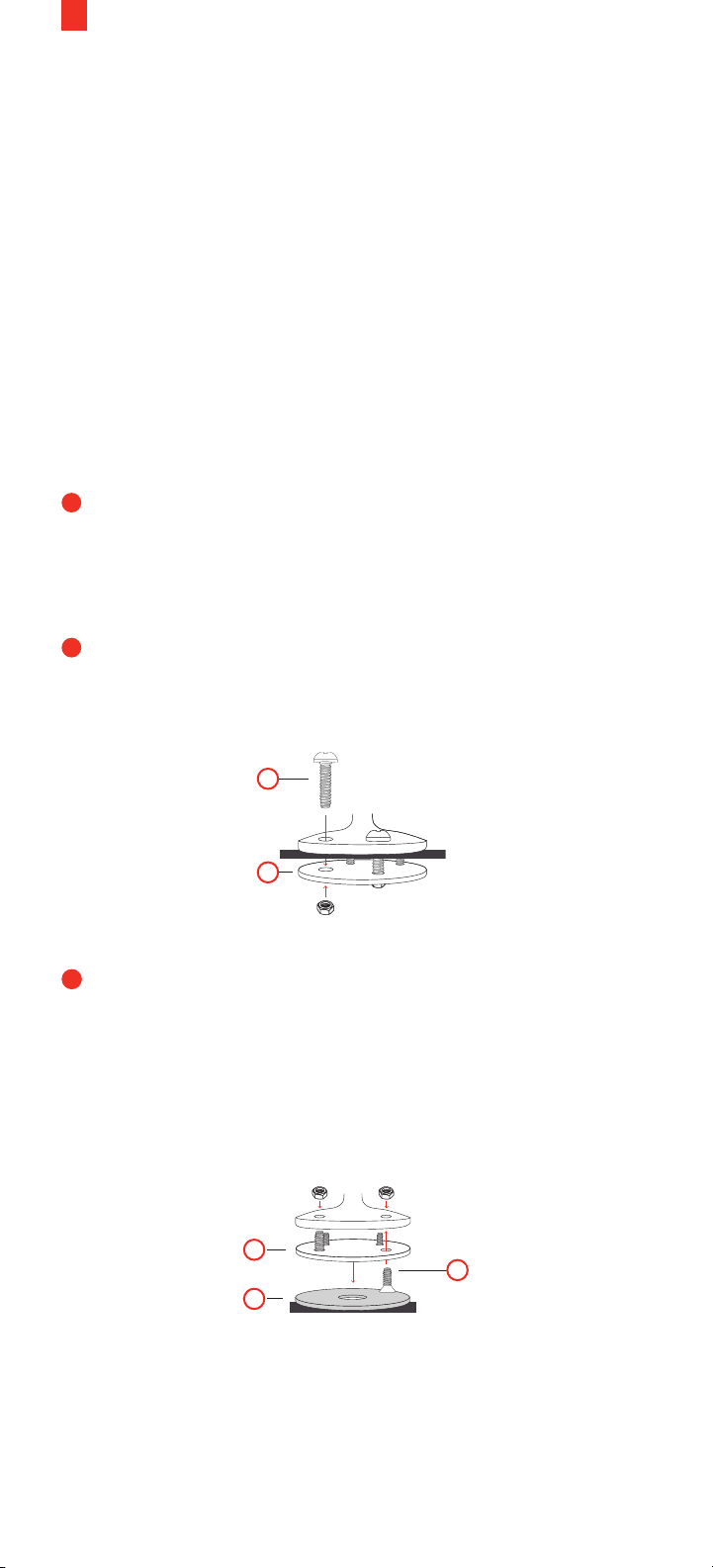
5. Mount the Ehubo
The Ehubo can be mounted on the dashboard or windshield
(where permitted by law where the vehicle is being operated).
Use either the adhesive tape (supplied for the windshield mount)
or the suction cup for temporary installation on a flat surface.
NOTE: Choose the mounting location for your Ehubo carefully
and ensure that it complies with all local regulations. Ensure
that the Ehubo does not impair the driver’s visibility, does not
pose a risk in the event of an accident, does not interfere with
any systems used in the operation of the vehicle, does not block
or impair the deployment of the airbag, and has a good view
of the sky. Choose a location that does not expose the Ehubo
to excessive temperature or vibration. Contact your account
manager if you prefer a suction cup mount.
1
Perform one of the three installation procedures:
1A - PERMANENT MOUNT (dashboard)
1B - TAPE MOUNT (windshield or flat surface)
1C - SUCTION CUP MOUNT (windshield or flat surface).
1A
PERMANENT MOUNT
Attach mount to the dash using the mounting plate (B),
screws and nuts (H).
H
B
1B
TAPE MOUNT
• Clean the flat surface with the alcohol wipe (A)
• Fit the mounting plate (B) to the mount using counter sunk
screws/holes and nuts (G)
• Apply adhesive tape (C) to the mounting plate and firmly
press to the surface
B
G
C
Page 13
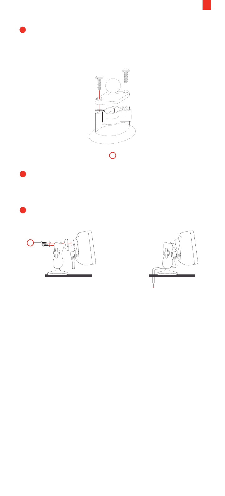
1C
SUCTION CUP MOUNT
• Clean the windshield surface with the alcohol wipe (A)
• Fit the composite diamond base on the suction cup base
using the supplied screws.
M
2
Attach the Ehubo to the mount using screws and washers
(F). Use of the washers is essential to reliably secure the
device!
11
3
Route the wiring out of the way and down the back of the
dashboard.
F
RAM
RAM
NOTE: Do not reuse the nylon-insert lock nuts (nyloc) if swapping
the mounting option; use unused nuts (supplied).
Page 14

12
6. Standard Installation (with ECM Connection)
NOTES
• If you are operating a pre-2000 vehicle or post-2000 vehicle
with no ECM connection (e.g. mechanical engine), refer to
Installing the Ehubo – No Electronic Control Module (ECM)
connection.
• The engine must be turned o prior to installing Ehubo.
• Power supply must not be taken from any Anti-lock Braking
System (ABS) / Electronic Braking System (EBS).
6.1 HARDWARE
1
Connect the 8-way connector (M) on the extendable cable (N)
to the corresponding connector on the ECM Y-cable (O). Secure
with the cable clamp (J) included in your cable kit.
2
Remove the vehicle’s diagnostic connector (data connector)
from the bracket or panel where it is fastened. Consult your
vehicle’s maintenance guide to properly remove panels, as
required.
3
Connect the vehicle’s diagnostic connector to the mating
connector on the ECM Y-cable (L2) and secure by twisting the
collar until it locks into place (tug lightly to check). Your Ehubo
display screen should power on at this point with a green LED
(P) above the display.
4
Feed the second connector on the ECM Y-cable (L1) into the
2
existing vehicle diagnostic connector housing and fasten to
the vehicle.
5
Finalize by following the on-screen instructions. (See section
6.2) After the checks are successfully completed, the Pending
Assignment, or the Ehubo home screen (if unit is assigned to a
vehicle) is displayed.
6
Store all unused wires neatly, insulated and secured using cable
ties. Reinstall any dashboard pieces or panels removed during
installation. Remove the screen protection film from the Ehubo
display screen. Ensure the driver-required manual and visor
cards are in the vehicle.
NOTES
If additional wires are required for monitoring activity through the
three digital inputs, connect to their respective sources with an inline 3A fuse listed in section 4.3.
Electronic logs are activated in Depot after installation. Contact
your Customer Success Account Manager for more information,
if needed.
Page 15
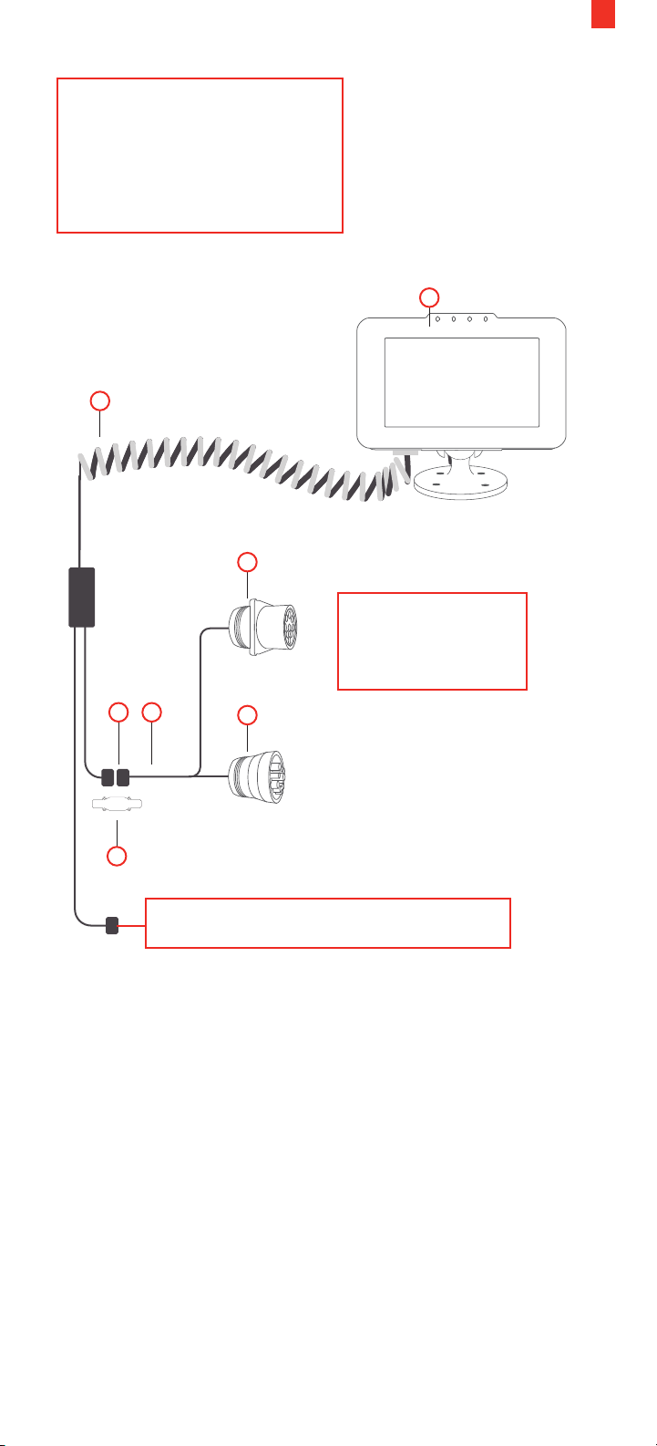
The Ehubo needs a permanent
power source and a good view
of the sky to operate optimally.
The curly cable must remain
above the dash.
N
13
P
EROAD
RAM
L1
The ECM cable can
vary depending on
the vehicle model.
OM
J
L2
Secure the connector with electrical tape.
The Ehubo shuts down to a lower power mode and draws a very
small current from the vehicle supply when the vehicle is o.
Remove the Ehubo permanent power fuse if the vehicle is in
storage or parked up for more than a month to avoid discharging
the vehicle battery.
Page 16
14
6.2 RUNNING THE INSTALL WIZARD (WITH ECM CONNECTION)
You must run the Install Wizard to complete your installation on
vehicles with an ECM connection. Typically, these vehicles were
manufactured in the year 2000 or later. Perform the following
steps to run the Install Wizard.
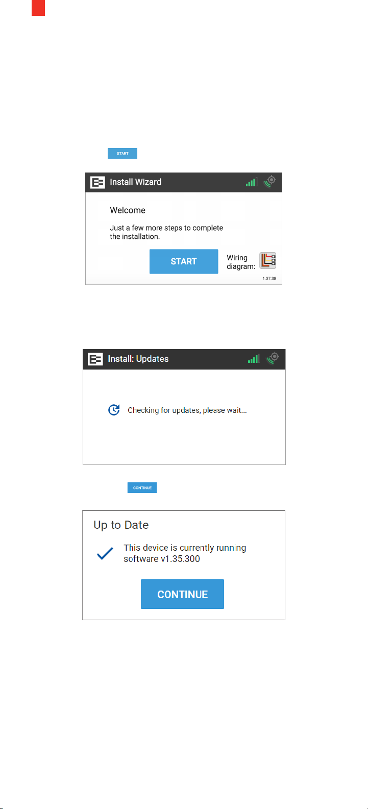
1. The Welcome screen appears once the Ehubo is physically
installed and the vehicle is powered ON.
Tap the Start button.
The Install Wizard displays a message that it is checking for
updates. Please wait until this cycle is completed and the Up to
Date screen appears.
2. Tap the Continue button in the Up to Date screen.
Page 17
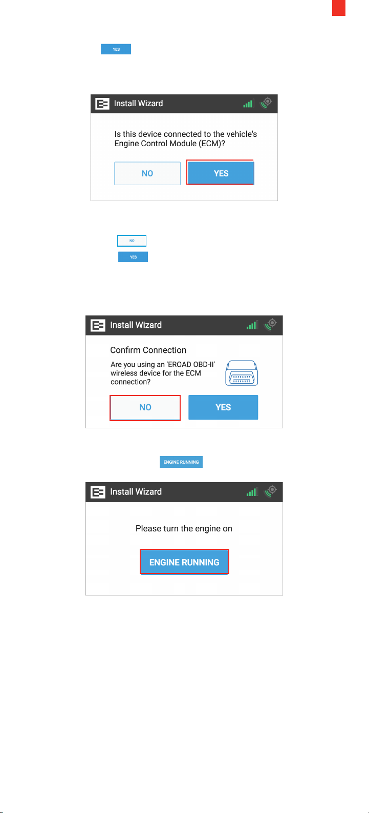
3. Tap the Yes button in this screen after installing the
EROAD ECM Y-cable and ensuring that the device is properly
connected to the ECM.
4. The following prompt displays if you are on the latest firmware.
4A. Tap the No button when using the ECM Y-cable.
4B. Tap the Yes button only if you've installed the
device in a light or medium-duty vehicle not equipped with a
standard, round 9-pin or 6-pin diagnostic connector, and you
are using this adapter.
15
5. Turn the engine ON and ensure that it is running (not just ON).
Tap the Engine Running button.
Page 18
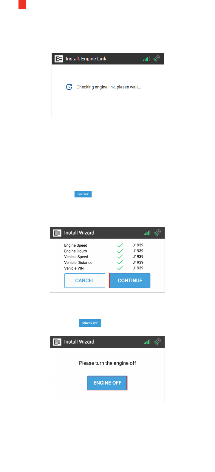
16
The Ehubo starts counting down as it receives data from the
ECM. You can watch the seconds tick down until it is ready for
the next step.
The Ehubo displays the system checks on engine speed and
hours, as well as vehicle speed, distance, and VIN. This means that
it has retrieved all required data from the ECM.
This example uses the J1939 protocol, which displays for new
trucks. Vehicles using the older communication standard J1708
would also display data on this screen.
6. Tap the Continue button.
NOTE: Contact EROAD at [email protected] if you see a red
X rather than green check marks or if the screen displays the
"Something is not quite right" message.
7. Physically turn OFF the truck. Notice the key icon has turned
red, which is located on the upper right corner of the Ehubo.
8. Tap the Engine O button.
Page 19
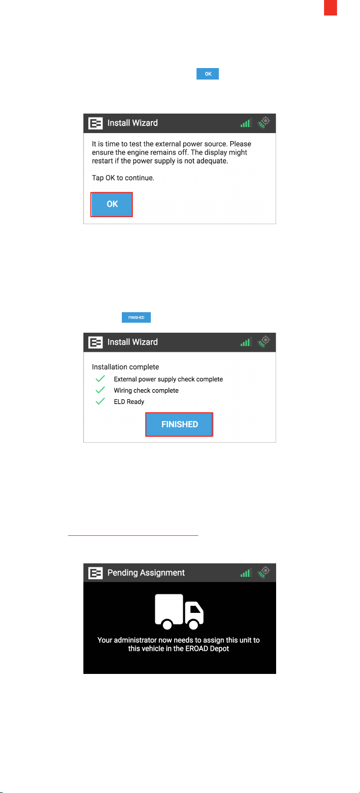
9. The Ehubo is now testing the external power source to ensure
that the device is receiving the proper voltage from the
diagnostic connector. Tap the OK button.
NOTE: The device might restart if the power supply is not
adequate.
Next, the green check marks on the Installation Complete screen
indicate that the unit has good external power, the wiring checks
are complete, and the system is now ELD ready.
ELD ready means that this vehicle is now ready to be enabled in
Depot to collect electronic logs on the device.
17
10. Tap the Finished button.
You've just successfully completed the installation wizard. The
following Pending Assignment screen appears until you assign
the Ehubo to a vehicle in the Depot application.
NOTE: Enabling the device is typically performed in the Depot
application by your back oce personnel.
See the Assign an Ehubo to a Vehicle training lesson for more
information.
Page 20
18
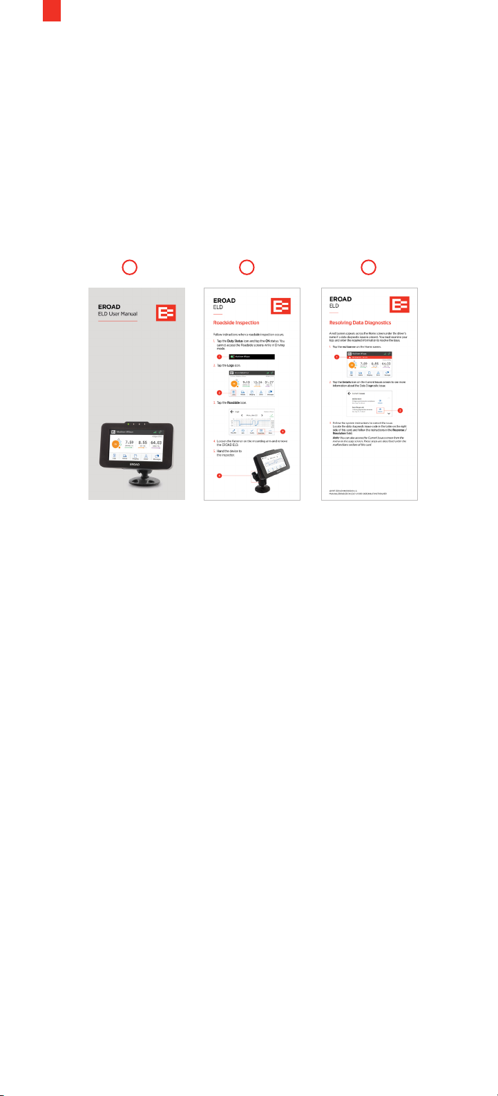
11. Place the following documents in the truck cab, which came in
the Ehubo box:
1. EROAD ELD User Manual
2. Roadside Inspection visor card
3. Resolving Data Diagnostic visor card
These documents are required to be carried in the vehicle by the
federal ELD mandate. Drivers might be cited during an inspection
if they do not have these documents.
1 2 3
Page 21
6.3 TROUBLESHOOTING ECM INSTALLATIONS
The following issues might occur on ECM installation. See the pin
diagrams in the Appendix for more information.
19
Issue or
Symptom
Device is not
powering on or
remains blank
ECM cable
does not match
or fit within
the existing
mounting hole
or bracket on
the vehicle
Cause Resolution
• No power
on the
diagnostic
connector
• Faulty ECM
cable
• Ensure the vehicle engine
is running
• Ensure there is 1224V on the diagnostic
connector by referring to
the appropriate pin-out
diagram
• Vehicle must be repaired
to restore power to the
connector if less than 8V
is measured
• Try a dierent ECM cable,
if others are available
• Contact EROAD if there
are no alternative cables
available
• Wrong cable
selected or
shipped
• Try a dierent ECM cable
if others are available;
note the subtle dierence
between screw-nut and
flange-style connectors
• Contact EROAD if there
are no alternative cables
available
No ECM data is
detected when
the installation
wizard is run
(receiving all
red Xs) or the
Something is
not quite right
screen appears
• ECM Y-cable
is missing or
not installed
correctly
• An older
Ehubo
device is
used on a
MY 2007
or older
truck that
has only an
SAE J1708/
J1587 ECM
interface
• Ensure that the correct
ECM cable has been
installed
• Double check that the
ECM cable is correctly
connected to both the
Ehubo cable and the
vehicle’s diagnostic
connector
• Check the year in
which the truck was
manufactured
• Contact EROAD for an
updated Ehubo that
supports SAE J1708/J1587
if the Ehubo serial number
begins with 0300
NOTE: Send a message to EROAD support if you need
assistance at [email protected].
Page 22
20
7. Non-Standard Installation
(without ECM Connection)
Use these instructions if you are installing the Ehubo into a pre-2000
vehicle or post-2000 vehicle with no ECM connection available.
Review the instructions and diagrams carefully before you begin.
NOTES
• The engine must be turned o prior to installing the Ehubo.
• Power supply must not be taken from any anti-lock braking
system/electronic braking system (ABS/EBS).
7.1 HARDWARE
1
Connect the 10-way connector (Q) on the extendable cable (N)
to the corresponding connector on the Ehubo wiring harness
(E). Secure with cable clamp (J) included in your cable kit.
2
Connect the black wire on the Ehubo wiring harness (E) to an
appropriate grounding location that is fit for that purpose.
3
Connect the red wire on the wiring harness to the in-line 2A
fuse (D) (included), and then to a permanent power source.
NOTE: Ensure there is a constant 12-24V when the key is
inserted, with the engine running, and also when the key is not
inserted and the engine is o.
4
Connect the yellow wire to an in-line fuse (D), then to the
engine or ignition switched power source. Do not connect to an
accessory wire.
NOTE: It is strongly recommended to connect to a source with
a constant 12-24V when the engine is running, and zero volts
when it is not for accurate idle reporting.
You may connect to an ignition source with a constant 12-24V
when the key is in the ON position, and zero volts when the
key is in the accessory (ACC) and OFF positions, if this is not
possible.
5
(Optional) If additional wires (orange, brown and gray) (R) from
the wiring harness are required for monitoring activity on the
three digital inputs, connect to their respective sources with an
in-line 3A fuse.
6
Finalize by following the on-screen instructions. (See section
7.2) After the checks are successfully completed, the Pending
Assignment, or the Ehubo home screen (if unit is assigned to a
vehicle) is displayed.
7
Store all unused wires neatly, insulated, and secured using cable
ties. Reinstall any dashboard pieces or panels removed during
installation. Remove the screen protection film from the Ehubo
display screen. Ensure the driver-required manual and visor
cards are in the vehicle.
NOTE: Electronic logs are activated in Depot after installation.
Contact your Customer Success Account Manager for more
information, if needed.
Page 23
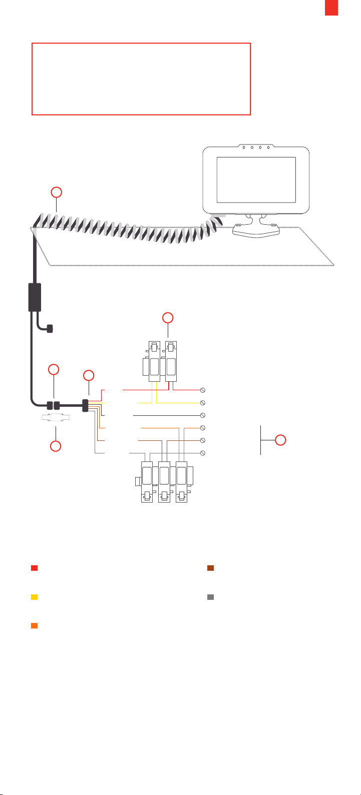
The Ehubo needs a permanent power
source and a good view of the sky to
operate optimally.
The curly cable must remain above the dash.
N
EROAD
EROAD
21
D
IGN
Q
J
E
RED
YELLOW
BLACK
ORANGE
BROWN
GRAY
+ve
Permanent Power (12V or 24V)
Switched Power (Engine on/o)
Ground
Digital input 1
Digital input 2
Digital input 3
3A
3A
3A
R
(Fuse note) You must fuse the following wires when connected for
short-circuit protection:
RED – Permanent Power
(Fuse supplied)
YELLOW – Switched
Power (Fuse supplied)
ORANGE - Digital Input 1
(3A Fuse)
BROWN - Digital Input 2
(3A Fuse)
GRAY - Digital Input 3
(3A Fuse)
The Ehubo shuts down to a lower power mode and draws a very
small current from the vehicle supply when the vehicle is o.
Remove the Ehubo permanent power fuse if the vehicle is in
storage or parked up for more than a month to avoid discharging
the vehicle battery.
Page 24
22
7.2 RUNNING THE INSTALL WIZARD (NON-ECM INSTALLATION)
You must run the Install Wizard to complete your installation on
vehicles with a non-ECM connection. Typically, these vehicles
were manufactured in the year 1999 or earlier. This device is hardwired for ground, permanent power, and ignition.
Perform the following steps to run the Install Wizard.
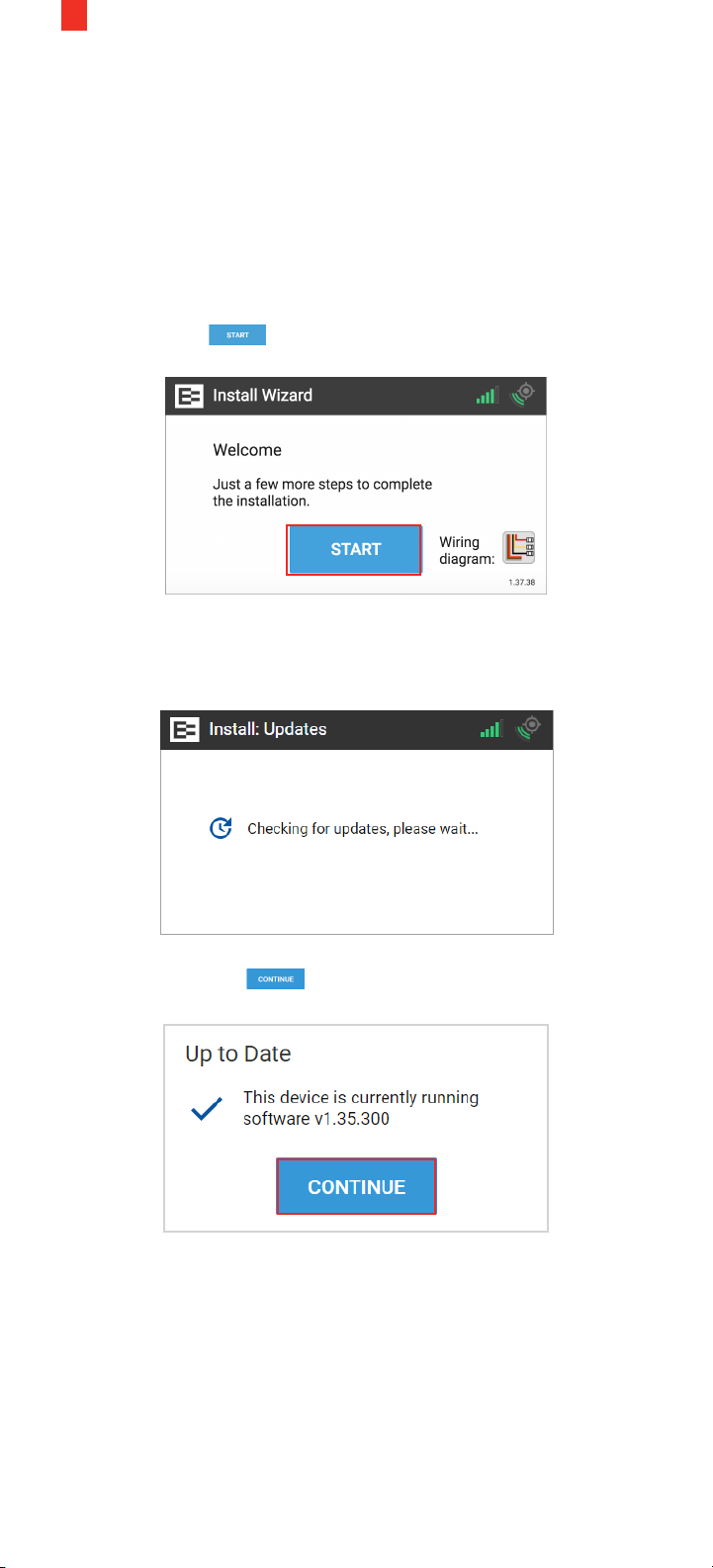
1. The Welcome screen appears once the Ehubo is physically
installed and the vehicle is powered ON.
Tap the Start button.
The Install Wizard displays a message that it is checking for
updates. Please wait until this cycle is completed and the Up to
Date screen appears.
2. Tap the Continue button in the Up to Date screen.
Page 25
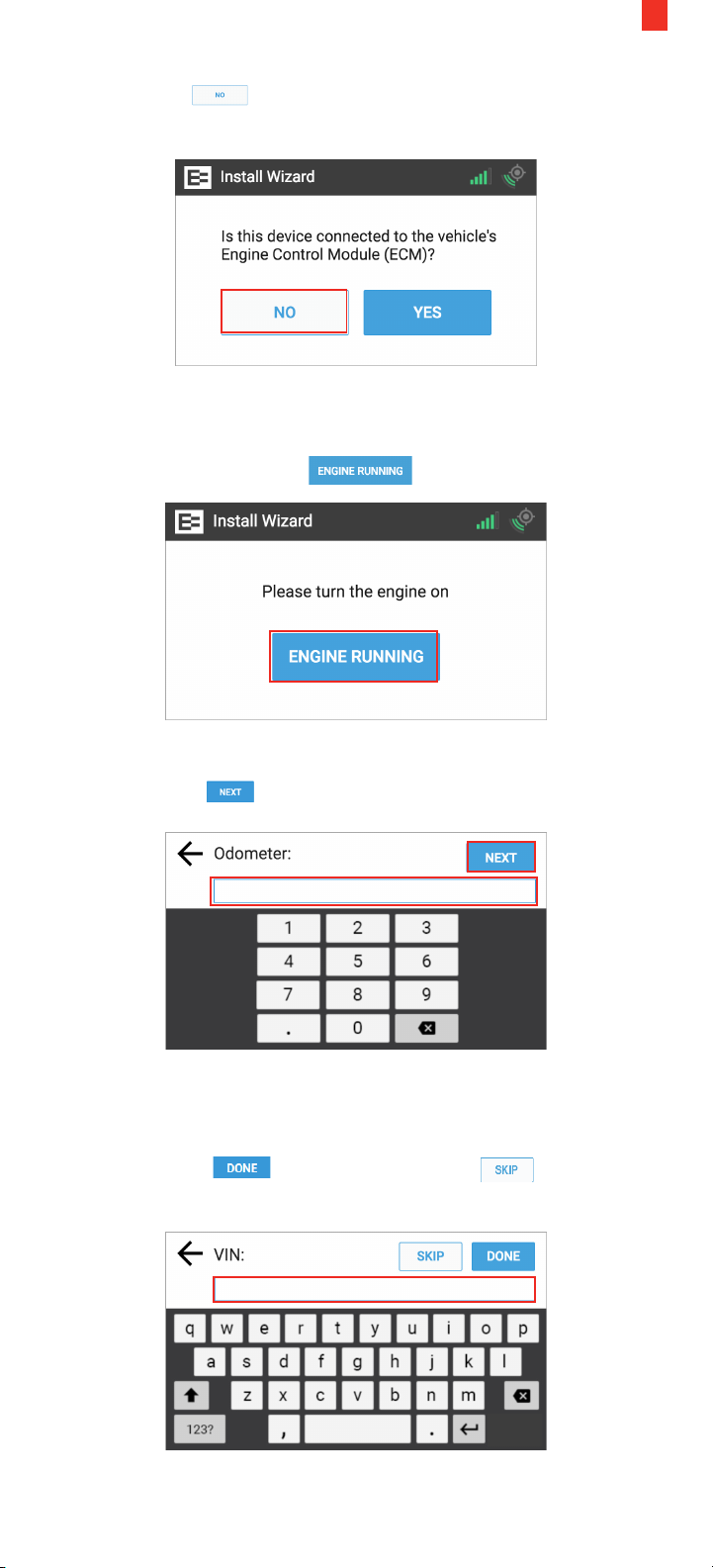
3. Tap the No button in the ECM prompt, because it is not
connected to the ECM.
4. Turn the engine ON until the key symbol in the upper right
corner of the Ehubo turns green.
5. Tap the Engine Running button.
23
6. Enter the vehicle's reading in the Odometer field on the screen.
7. Tap the Next button.
8. (Optional) Enter the vehicle's identification number (VIN) in
the VIN field on screen. You may skip this step if you do not
have access to the VIN.
9. Tap the Done button or tap the Skip button if
you do not have the information.
Page 26
24
10. Turn the engine OFF. The key icon on the device should
turn red.
11. Tap the Engine O button.
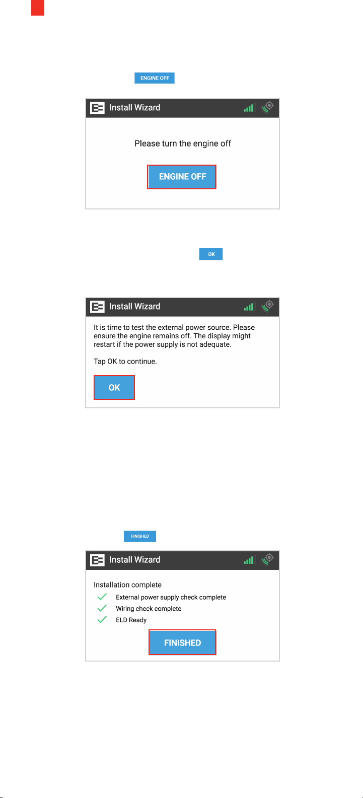
12. The Ehubo is now testing the external power source to ensure
that the device is receiving the proper voltage from the
diagnostic connector. Tap the OK button to continue.
NOTE: The device might restart if the power supply is not
adequate.
Next, the green check marks on the Installation Complete screen
indicate that the unit has good external power, the wiring checks
are complete, and the system is now ELD ready.
This vehicle is now set up as a pre-2000 vehicle in the Depot
application, which means that you can still activate EROAD logs if
you want to on this truck.
Talk to your Customer Success specialist for more information.
13. Tap the Finished button.
Page 27
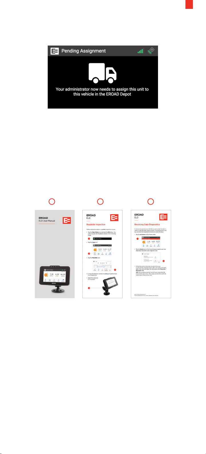
You've just successfully completed the installation wizard. The
following Pending Assignment screen appears.
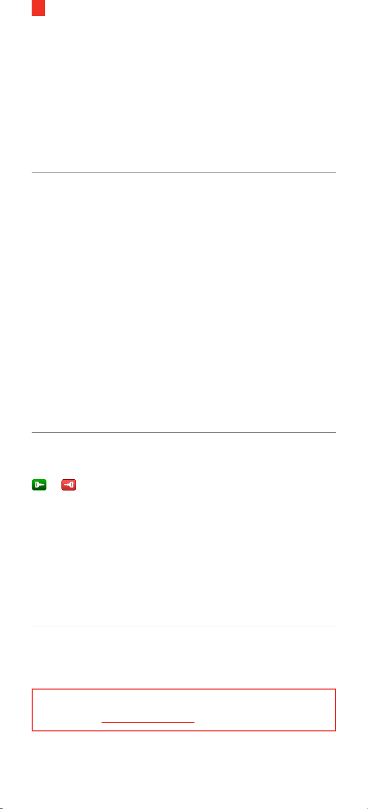
14. Place the following documents in the truck cab, which came in
the Ehubo box:
1. EROAD ELD User Manual
2. Roadside Inspection visor card
3. Resolving Data Diagnostic visor card
These documents are required to be carried in the vehicle by the
federal ELD mandate. Drivers might be cited during an inspection
if they do not have these documents.
25
1 2 3
Page 28
26
7.3 TROUBLESHOOTING NON-ECM INSTALLATIONS
This section provides some solutions if the installation of your
Ehubo is unsuccessful or the Ehubo doesn’t perform as expected.
The following issues might occur on non ECM installations. See
the pin diagrams in the Appendix for more information, if needed.
Issue or
Symptom
Device is not
powering on or
remains blank
Engine on/
o icon shows
incorrectly
Cause Resolution
• Red permanent
power wire is
not connected
properly or is not
connected to a
good source
• Black ground
wire is not
connected to a
good ground
• Main cable
has become
unplugged
from the back
of the unit
• Check that the
permanent power
has been connected
correctly and there is
12-24V when the key
is in the OFF, ON, and
RUN positions.
• Ensure that there
is a good ground
connected to the
black wire
• Ensure that the main
cable is fully seated in
the connection on the
back of the unit.
• Ensure that the fuse
inline is connected
per the installation
instructions, and the
2A fuse is inserted
• Ignition
(switched
power) is not
connected
properly
• Ensure that switched
power has been
connected correctly
and there is 12-24V
when the key is in
the ON and RUN
positions, and there
are zero volts when
the key is in the OFF
positions
• Ensure that the fuse
in-line is connected
per the installation
instructions, and the
2A fuse is inserted
NOTE: Send a message to EROAD support if you need
assistance at [email protected].
Page 29
8. OBD-II Installation
Using the OBD-II Bluetooth® connection allows light vehicles to use
ELD technology. A dongle provides the connection to the ECM and
plugs into the OBD-II port. Ground, permanent power, and ignition
are accomplished using the three-wire installation procedure.
Use these instructions if you are installing the Ehubo into a lighter
class vehicle (class 1-6) with an OBD-II diagnostic connector.
Review the instructions and diagrams carefully before you begin.
NOTES
• The engine must be turned o prior to installing the Ehubo.
• Power supply must not be taken from any anti-lock braking
system/electronic braking system (ABS/EBS).
8.1 HARDWARE
1
Connect the 10-way connector (Q) on extendable cable (N) to
the corresponding connector on the Ehubo wiring harness (E).
Secure with cable clamp (J) included in your cable kit.
2
Connect the black wire on the Ehubo wiring harness (E) to an
appropriate grounding location that is fit for that purpose.
3
Connect the red wire on the wiring harness to the inline 2A fuse
(D) (included), and then to a permanent power source.
27
NOTE: Ensure there is a constant 12-24V when the key is
inserted, with the engine running, and also when the key is not
inserted and the engine is o.
4
Connect the yellow wire to an inline fuse (D), then to the
engine or ignition switched power source. Do not connect to an
accessory wire.
NOTE: It is strongly recommended to connect to a source with a
constant 12-24V when the engine is running, and zero volts when
it is not for accurate idle reporting.
You may connect to an ignition source with a constant 12-24V
when the key is in the ON position, and zero volts when the key is
in the accessory (ACC) and OFF positions, if this is not possible.
5
(Optional) If additional wires (orange, brown and gray) (R) from
the wiring harness are required for monitoring activity on the
three digital inputs, connect to their respective sources with an
inline 3A fuse.
6
Insert the EROAD OBD-II wireless adapter into the OBD-II port
of the vehicle ensuring that it is fully seated in position.
7
Finalize by following the on-screen instructions. (See section
8.2) After the checks are successfully completed, the Pending
Assignment, or the Ehubo home screen (if unit is assigned to a
vehicle) is displayed.
8
Store all unused wires neatly, insulated, and secured using cable
ties. Reinstall any dashboard pieces or panels removed during
installation. Remove the screen protection film from the Ehubo
display screen. Ensure the driver-required manual and visor
cards are in the vehicle.
Page 30

28
NOTE: Electronic logs are activated in Depot after installation.
Contact your Customer Success Account Manager for more
information, if needed.
The Ehubo needs a
permanent power source
and a good view of the
sky to operate optimally.
The curly cable must
remain above the dash.
EROAD
EROAD
N
D
Q
IGN
E
RED
YELLOW
J
BLACK
ORANGE
BROWN
GRAY
+ve
Permanent Power (12V or 24V)
Switched Power (Engine on/o)
Ground
Digital input 1
Digital input 2
Digital input 3
3A
3A
3A
R
X
Insert the EROAD OBD-II wireless adapter
into the OBD-II port of the vehicle
(Fuse note) You must fuse the following wires when connected for
short-circuit protection:
RED – Permanent Power
(Fuse supplied)
YELLOW – Switched
Power (Fuse supplied)
BROWN - Digital Input 2
(3A Fuse)
GRAY - Digital Input 3
(3A Fuse)
ORANGE - Digital Input 1
(3A Fuse)
The Ehubo shuts down to a lower power mode and draws a very
small current from the vehicle supply when the vehicle is o.
Remove the Ehubo permanent power fuse if the vehicle is in
storage or parked up for more than a month to avoid discharging
the vehicle battery.
Page 31
8.2 RUNNING THE INSTALL WIZARD (OBD-II INSTALLATIONS)
You must run the Install Wizard to complete your installation on
vehicles with an OBD-II adapter. Perform the following steps to
run the Install Wizard.
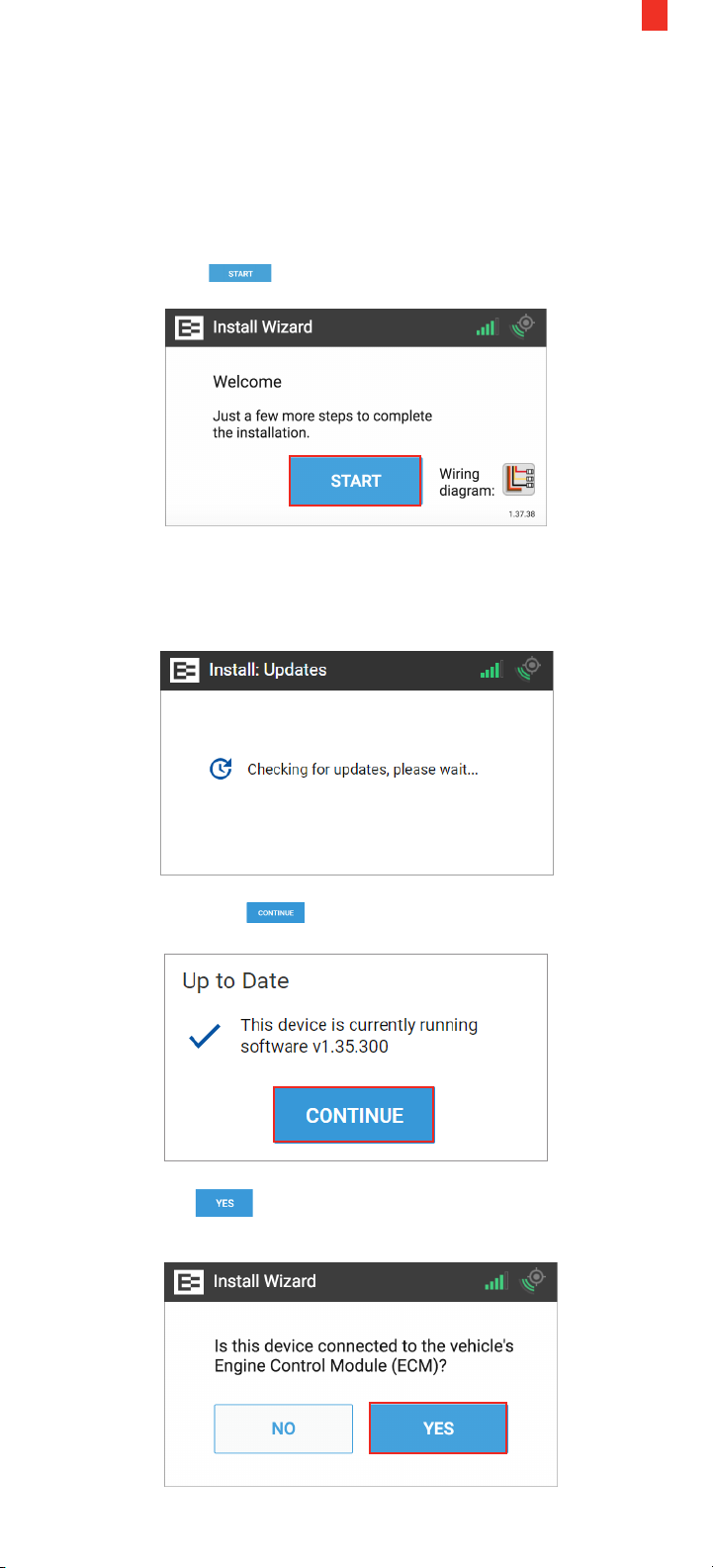
1. The Welcome screen appears once the Ehubo is
physically installed and the vehicle is powered ON.
Tap the Start button.
The Install Wizard displays a message that it is checking for
updates. Please wait until this cycle is completed and the Up to
Date screen appears.
29
2. Tap the Continue button in the Up to Date screen.
3. Tap the Yes button in this screen after ensuring that the
device is properly connected to the ECM.
Page 32
30
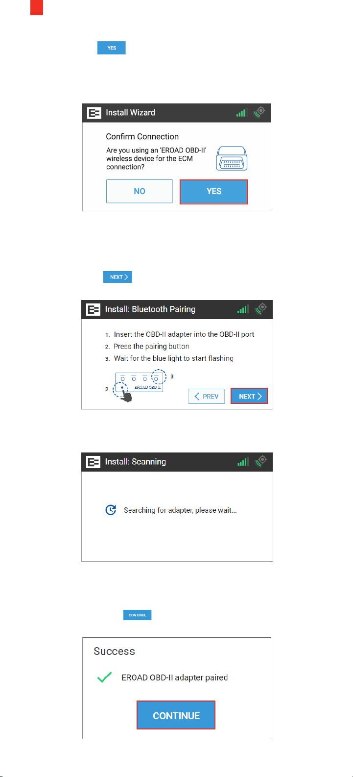
4. Tap the Yes button if you've installed the device in a
light or medium-duty vehicle not equipped with a standard,
round 9-pin or 6-pin diagnostic connector, and you are using
this adapter.
5. Insert the OBD-II adapter into the OBD-II port.
6. Press the Pairing button on the adapter.
7. Wait for the blue light to start rapidly flashing.
8. Tap the Next button on the screen.
The device begins searching for the OBD-II adapter, so please
wait until this step is completed.
The Success screen appears when the EROAD OBD-II adapter
pairing is completed.
9. Tap the Continue button.
Page 33
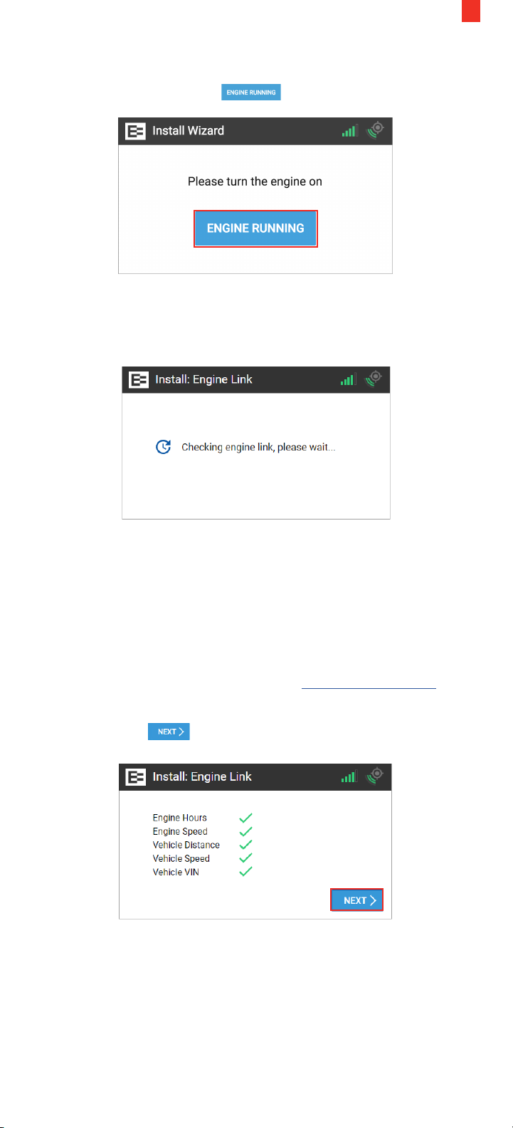
10. Turn the engine ON and ensure that it is running (not just ON).
11. Tap the Engine Running button.
The Ehubo starts counting down as it receives data from the
OBD-II adapter.
Watch the seconds tick down until it is ready for the next step.
31
Next, the Ehubo displays the system checks on engine speed and
hours, vehicle speed, distance, and VIN. This means that it has
retrieved all required data.
NOTE: A red X instead of a green check mark appears, or the
"Something is not quite right" screen appears, if you are missing
data. You might be prompted to enter the odometer reading
or the VIN. Check the Troubleshooting section 8.3, if you need
assistance. You may contact EROAD at [email protected]
after completing the troubleshooting steps, if needed.
12. Tap the Next button.
13. Physically turn OFF the truck. Notice the key icon has turned
red, which is located on the upper right corner of the Ehubo.
Page 34
32
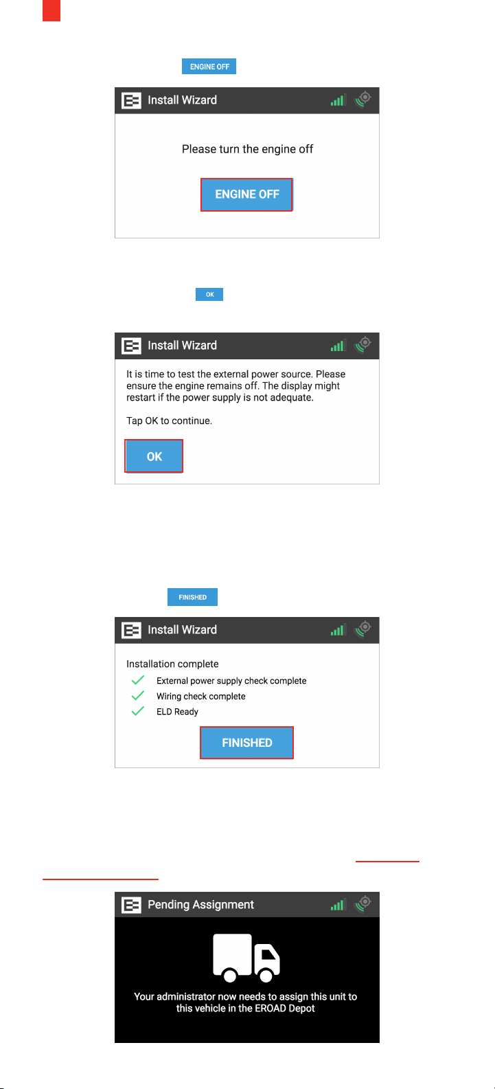
14. Tap the Engine O button.
15. The Ehubo is now testing the external power source to ensure
that the device is receiving the proper voltage from the diagnostic
connector. Tap the OK button to continue.
Note: The device might restart if the power supply is not adequate.
Next, the green check marks on the Installation Complete screen
indicate that the unit has good external power, the wiring checks
are complete, and the system is now ELD ready. ELD ready
means that this vehicle is now ready to be enabled in Depot to
collect electronic logs on the device.
16. Tap the Finished button.
You've successfully completed the installation wizard. The
following Pending Assignment screen appears until you assign
the Ehubo to a vehicle in the Depot application.
NOTE: Enabling the device is typically performed in the Depot
application by your back oce personnel. See the Assign an
Ehubo to a Vehicle training lesson for more information.
Page 35
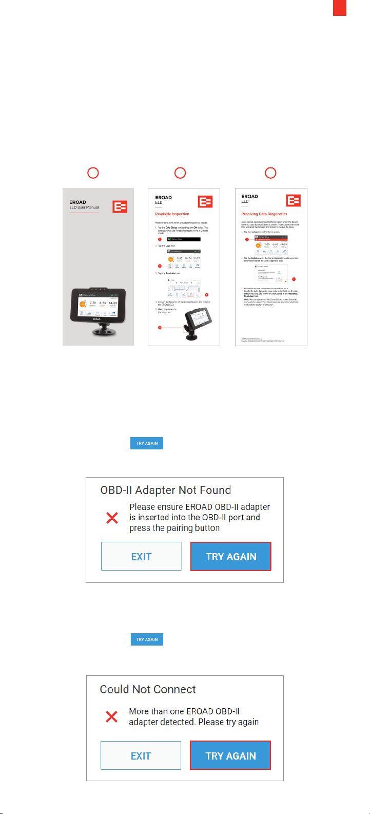
17. Place the following documents in the truck cab, which came in
the Ehubo box:
1. EROAD ELD User Manual
2. Roadside Inspection visor card
3. Resolving Data Diagnostic visor card
These documents are required to be carried in the vehicle by the
federal ELD mandate. Drivers might be cited during an inspection
if they do not have these documents.
1 2 3
33
8.3 TROUBLESHOOTING OBD-II INSTALLATIONS
The OBD-II installation might fail if the OBD-II adapter is not
inserted properly into the OBD-II port before tapping the Pairing
button.
1. Tap the Try Again button if this occurs and repeat the
installation steps described in section 8.2.
The following error message occurs if there is more than one
OBD-II adapter detected while the installation wizard is running.
2. Tap the Try Again button if this occurs and repeat the
installation steps described in section 8.2.
Page 36
34
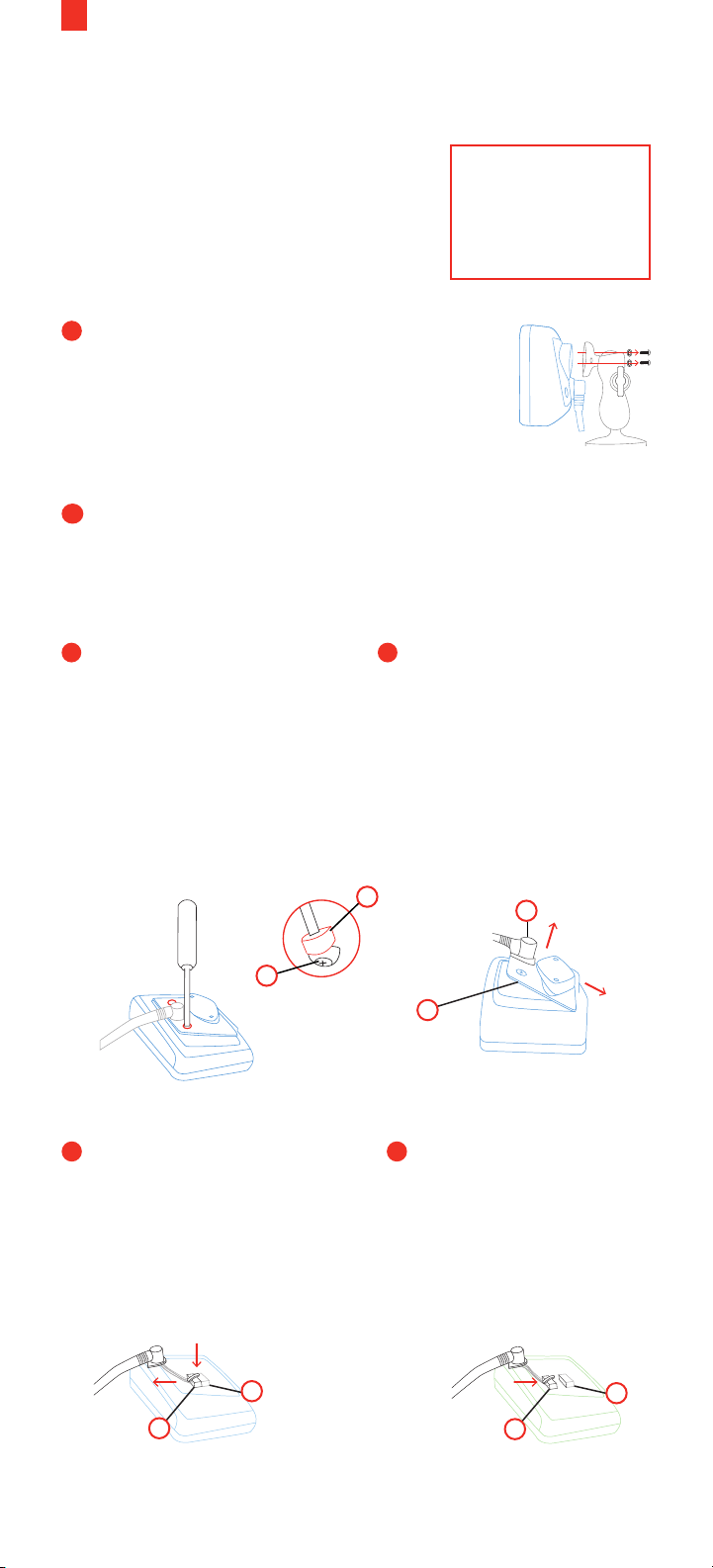
9. Replacement Installation
Replacing an existing Ehubo includes:
• Disconnect the power cable from the
existing Ehubo
• Connect it to the replacement Ehubo.
Perform the following steps:
1
Remove the existing Ehubo from its
mount and carefully place it screen down
on a clean, flat surface.
Make sure to not scratch or damage the
screen!
2
Unpack the replacement Ehubo and also place it
screen down on a clean, flat surface.
Make sure to not scratch or damage the screen!
3 4
Remove the rear hatch
security plugs (K) of
both, the existing and
the replacement Ehubo,
if applicable. This is
easily done by inserting
Lift the rear hatch (T)
o the existing Ehubo
and slide it o the cable
grommet (U). Lift the rear
hatch o the replacement
Ehubo.
a flat head screwdriver
and scooping out the
plug. Unwind the screw
underneath (S).
K
NOTE: Turn OFF
the engine prior
to replacing the
Ehubo
RAM
U
5
EXISTING EHUBO:
Push down the cable plug
latch to release the cable
plug (V) and carefully
slide the cable plug o the
internal connector (W).
W
V
S
T
6
REPLACEMENT EHUBO:
Carefully insert the cable
plug (V) into the internal
connector (W).
Ensure the cable plug
latch clicks into place to
safely secure the plug.
W
V
Page 37
35
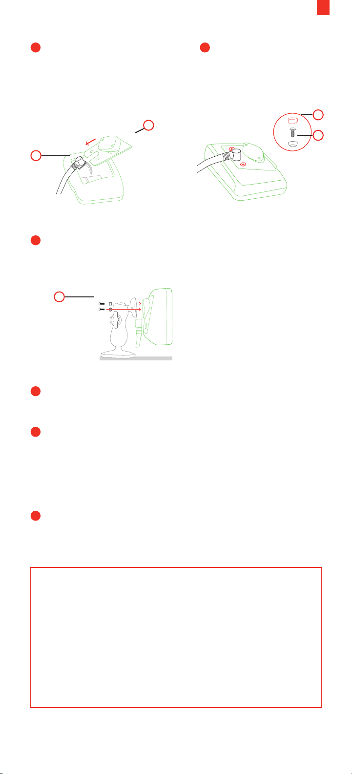
7 8
Slide the replacement Ehubo’s
rear hatch (T) onto the cable
grommet (U) and insert it into
the replacement Ehubo.
T
U
9
Mount the replacement Ehubo on the existing mount using
Insert the two rear
hatch screws (S) and
new security plugs (K),
if applicable.
the screws and washers (F) supplied with the replacement
Ehubo.
F
RAM
K
S
10
Pull the sticker and screen protection film o the
Ehubo screen.
11
The install wizard must be re-run to completion on the new
unit. Follow the instructions on the screen to complete the
installation. (See the Install Wizard instructions in previous
chapters for more information.) The installation is complete
when the Ehubo Home screen is displayed. This is the end
of the process.
12
Please place the uninstalled Ehubo in the replacement box
and return to EROAD, including any surplus parts.
You must rerun the Install Wizard when the Ehubo is powered
ON. Perform these steps if the system does not prompt you to
complete the Install Wizard.
• Press and hold the EROAD logo on the top left corner
of the Home screen for seven (7) seconds to access the
Diagnostics Mode screen. Alternatively, press and hold
Login if no one has logged into the Ehubo.
• Tap Install Wizard once the Diagnostic Mode screen
appears. Follow the applicable installation procedure for
your vehicle.
Page 38
36
10. Appendix
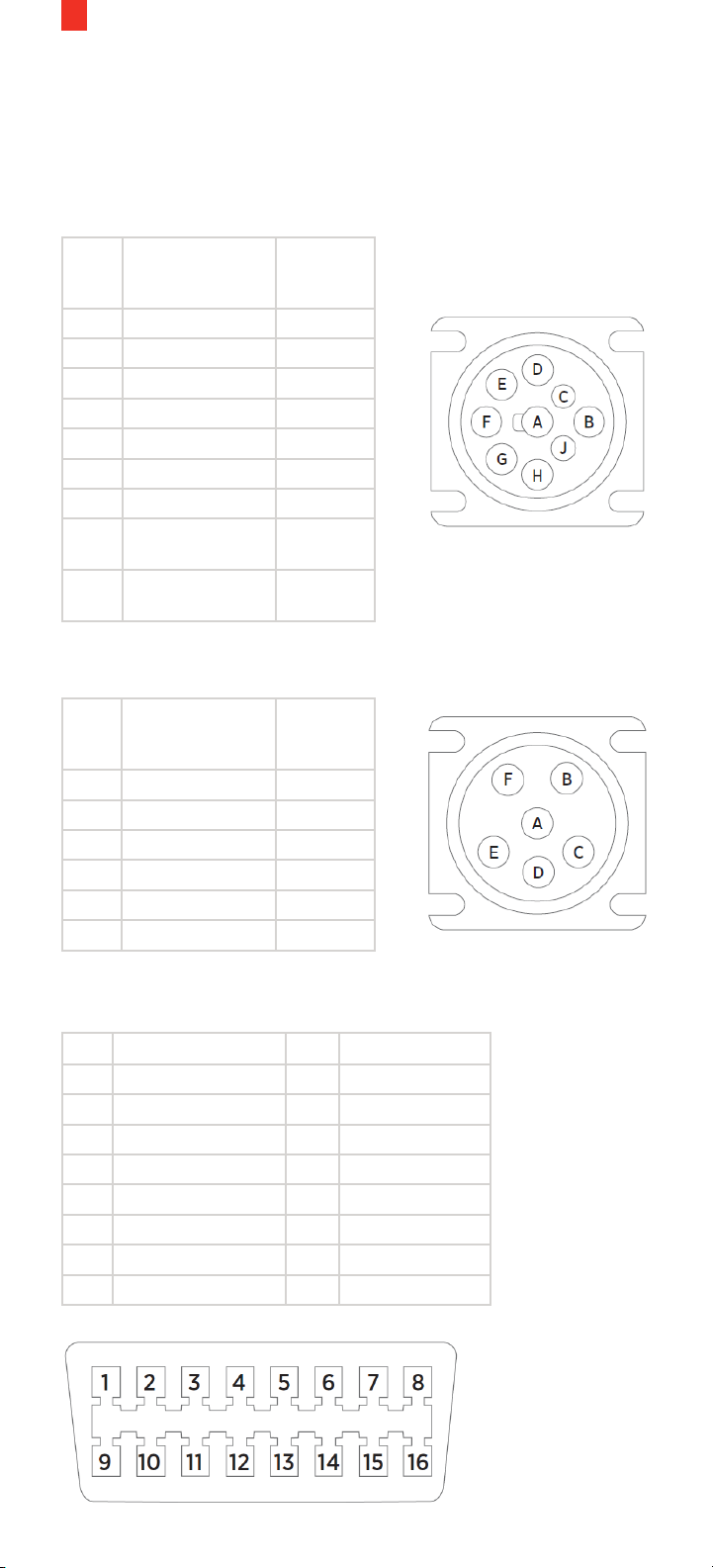
Use the following PIN diagrams, when directed by the respective
troubleshooting instructions.
9-Pin J-BUS Connector and Diagram
PIN Description Wire
Color
(Typical)
A Ground (Earth) Black
B 12V Power Supply Red
C J1939 + (Data +) Yellow
D J1939 - (Data -) Brown
E J1939 Shield White
F J1708/J1587 + Green
G J1708/J1587 - Blue
H Not connected/
CAN2 High
J Not connected/
CAN2 Low
6-Pin J-BUS Connector and Diagram
PIN Description Wire
Color
(Typical)
A J1587 + (Data +) Green
B J1587 - (Data -) Blue
C 12V Power Supply Red
D Not Connected
E Ground (Earth) Black
F Not Connected
OBD-II Connector and Pin-out Diagram
PIN Description PIN Description
1 Vendor Option 9 Vendor Option
2 J1850 Bus + 10 J1850 Bus
3 Vendor Option 11 Vendor Option
4 Chassis Ground 12 Vendor Option
5 Signal Ground 13 Vendor Option
6 CAN (J-2234) High 14 CAN (J-2234) Low
7 ISO 9141-2 K-Line 15 ISO 9141-2 Low
8 Vendor Option 16 Battery Power
Page 39

Page 40

38
EROAD.COM
Confidence in every mile.
 Loading...