

Page 1
EROAD Ehubo®
Installation Guide
Page 2
2 1
Congratulations on purchasing your EROAD Ehubo®
IMPORTANT: Do not install or use the Ehubo until you
have read this Installation Guide thoroughly.
EROAD recommends the use of a professional automotive technician to
install the Ehubo in your vehicle. Please make this Guide available to your
installer and keep it for future reference.
The Ehubo is easy to install by carrying out the following steps as described
in this Guide:
• Make sure to read EROAD’s Safety Information and follow
all standard safety precautions
• Choose a suitable mounting location and mount the Ehubo
• Install the Ehubo by connecting it to the vehicle
• Finalize the installation to ensure the Ehubo operates correctly
Please record the Ehubo’s serial number along with the vehicle ID or
number plate of the vehicle it is installed in. This information is required by
the administrator in the oce to activate the newly installed Ehubo. You can
use this page to record the vehicle ID and forward it to the oce.
We have provided the serial number of your Ehubo above.
After the install, you may use the panel above to record the name/ID of the
vehicle. Simply give this page to your EROAD Administrator to help them
link the Ehubo to a vehicle in the EROAD Depot.
Refer to “Replacement Installation” on page 10 if you are installing a replacement Ehubo
VEHICLE
NAME
Sticker with serial number goes here
Page 3

2 3
Please read carefully before beginning installation!
DISCLAIMER
It is the Customer’s sole responsibility to install and use the Ehubo (the Product) in a manner that
will not cause accidents, personal injury or property damage. The Owner of this Product is solely
responsible for observing safe driving practices
EROAD DISCLAIMS ALL LIABILITY FOR ANY USE OF THIS PRODUCT IN A WAY THAT MAY CAUSE
ACCIDENTS, DAMAGE OR VIOLATE THE LAW.
TO THE MAXIMUM EXTENT PERMITTED BY LAW, ALL REPRESENTATIONS AND WARRANTIES
(EXCEPT ANY WHICH MAY NOT LAWFULLY BE EXCLUDED) ARE EXPRESSLY EXCLUDED, INCLUDING
WITHOUT PREJUDICE TO THE GENERALITY OF THE FOREGOING, THE IMPLIED WARRANTIES OF
MERCHANTABILITY AND FITNESS FOR A PARTICULAR PURPOSE
As EROAD is continuously improving this Product, EROAD may make changes to the Product at any
time which may not be reflected in this document. Please contact your nearest EROAD oce if you
require any further assistance.
PERSONAL PROTECTIVE EQUIPMENT (PPE)
Federal regulations require wearing appropriate Personal Protective Equipment (PPE). Adherence to
this requirement is monitored and mandated by Environmental Health and Safety (EHS) personnel
and regulated and mandated by the U.S. Department of Labor Occupational Safety and Health
Administration (OSHA).
PPE may include items such as safety glasses, safety shoes, work gloves, hard hat, high visibility vest,
and work uniform. Make sure to comply with appropriate standards and check with customers or third
parties to verify whether they have additional PPE requirements.
INSTALLATION
• Installers and contractors must follow OSHA regulatory requirements for working on equipment, or
parts thereof, which are suspended or held aloft by use of slings, hoists, or jacks.
• Whenever the equipment is parked, the parking brake shall be set. Equipment parked on inclines
shall have the wheels chocked and the parking brake set.
• Equipment, or parts thereof, which are suspended or held aloft by use of slings, hoists, or jacks shall
be substantially blocked or cribbed to prevent falling or shifting before employees are permitted to
work under or between them.
• Installing and servicing electronic devices can be hazardous due to electrical components. Make sure
to create a safe working environment to avoid hazards and to ensure correct & safe installation &
operation.
• EROAD recommends the use of a qualified professional automotive technician to install the Ehubo.
Make this Installation Guide available to the appropriate personnel. Store it for future reference.
• To avoid damage do not run cables close to heat sources, sharp edges or other obstacles that might
damage them.
• Do not run cables directly next to safety-relevant devices.
• Do not damage existing wiring and components when drilling the dashboard.
• After installation, check that all safety-relevant equipment is working properly.
Important Safety Information
OPERATION
• Only operate or look at the Ehubo when it is safe to do so. Always keep your hands free to operate
the vehicle while driving. Your first consideration while driving should be road safety.
• To avoid driver distraction, the Ehubo screen is initially configured to automatically turn o when
movement is detected.
• Do not use sharp-edged objects on the Ehubo touch screen.
• The Ehubo is not waterproof. Do not spill any liquid on it.
• Protect the Ehubo from extreme temperatures. Operating
temperature for the Ehubo is between -4°F and 185°F.
• Always follow local regulations when disposing of the Ehubo.
• Do not dispose of the battery in trash cans, fire or water.
FCC COMPLIANCE STATEMENT
This device complies with part 15 of the FCC Rules. Operation is subject to the following two conditions:
(1) This device may not cause harmful interference, and (2) this device must accept any interference
received, including interference that may cause undesired operation.
Page 4
4 5
EROAD Ehubo
(pre-fitted wiring loom)
EROAD
Fuse kit
(permanent/switched power)
EROAD Ehubo®
Installation Guide
This installation guide
Cable ties
Rear hatch
security plugs
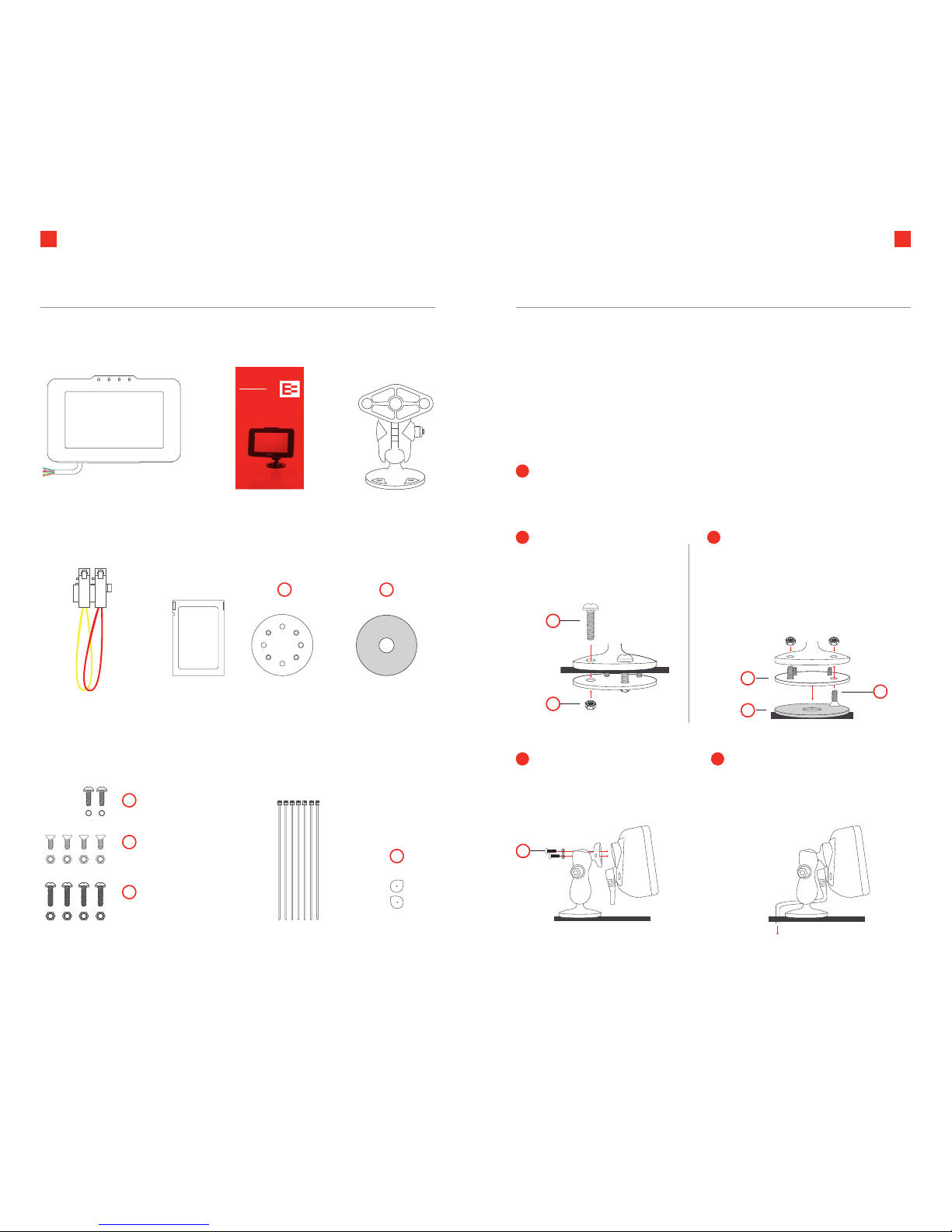
Inside the box
RAM
RAM
Ehubo mount
High–strength adhesive tape
(optional, for tape mount)
Mounting
plate
Screws, nuts and washers to mount Ehubo.
2 x ¾” screws + washers
4 x ½” counter sunk
screws + nyloc nuts
4 x 1” screws + nuts
TAPE MOUNT
Clean flat surface with alcohol wipe.
Fit mounting plate (A) to mount using
counter sunk screws/holes and nuts (D).
Apply adhesive tape (B) to mounting
plate and firmly press to surface.
PERMANENT MOUNT
Attach mount to dash
using mounting plate (A),
1” screws and nuts (E).
or
Attach Ehubo to the mount
using ¾” screws and washers (C).
Use of the washers is essential to
reliably secure the Ehubo!
Route the Ehubo wiring out of
the way and down the back of
the dashboard.
NOTE: If swapping mounting option do not re-use nyloc nuts, use unused nuts as supplied.
Insert the two rear hatch security plugs. The plugs are keyed and only fit in
their correct position. Proceed with 2A PERMANENT MOUNT (dashboard) or
2B TAPE MOUNT (windshield or flat surface).
1
2B2A
A
A
A
B
B
3 4
Mount the Ehubo
TECHNICAL CLEANING WIPE
Alcohol wipe
C
C
F
D
E
E
The Ehubo can be mounted on the dashboard or windshield. For windshield mount or
temporary installation on a flat surface please use the adhesive tape supplied.
NOTE: Choose the mounting location for your Ehubo carefully and ensure that it complies
with all local regulations. Make sure that the Ehubo does not impair the driver’s visibility,
does not pose a risk in the event of an accident, does not interfere with any systems used
in the operation of the vehicle, does not block or impair the deployment of the airbag, and
has a good view of the sky. Choose a location that does not expose the Ehubo to excessive
temperature or vibration.
Open your Ehubo box and please check that everything is inside.
D
Page 5
6 7
Install the Ehubo
NOTE
• The engine must be turned o prior to installing the Ehubo.
• Do not connect in any way to a CANBUS or other engine management system.
• Power supply must not be taken from any ABS/EBS braking system.
The Ehubo needs a permanent power source and a good view of the sky to operate
optimally. While the vehicle is o, the Ehubo will shut down to a low power mode and will
draw a very small current from the vehicle supply. Remove the Ehubo permanent power
fuse if the vehicle is in storage or parked up for more than a month to avoid discharging the
vehicle battery.
INSTALLATION
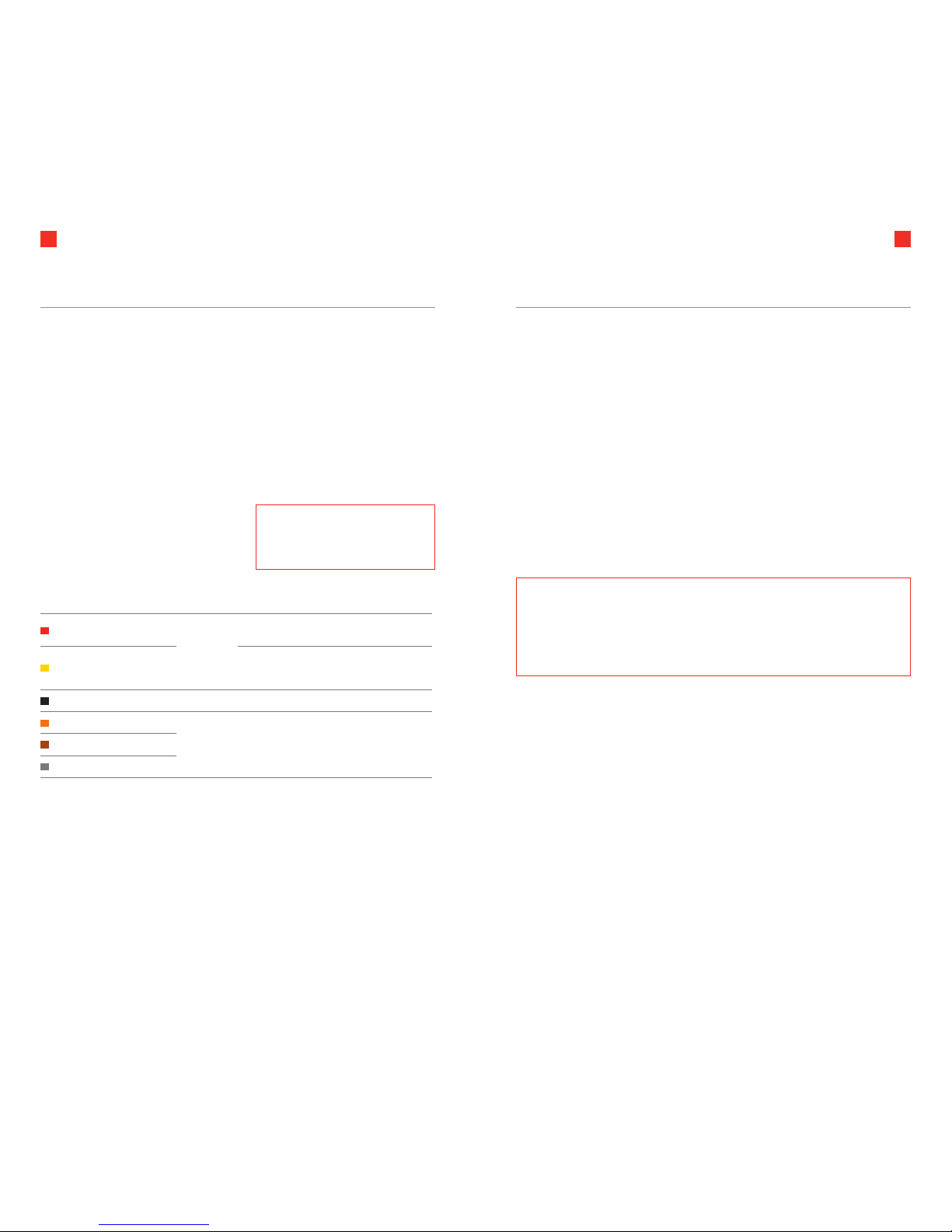
The Ehubo is fitted with a 10 way cable which is
used to connect to the vehicle and for optional
digital inputs.
WIRE FUNCTION FUSE NOTES
Red +12V / 24V DC Supply
Use supplied
fuse kit
Connect to a 12V or 24V DC permanent power
source.
Yellow Switched Power
Connect to a switched power source that is switched
on when the engine is running and o when the
engine is not running.
Black Ground Do not fuse Connect to a permanent Ground.
Orange Digital Input 1
Fuse
individually
with 3A fuse
Optional digital inputs for integration purposes. Brown Digital Input 2
Gray Digital Input 3
NOTE: If the screen remains black and does not prompt you to carry out some
checks, the wiring of the Ehubo might not be quite right.
Please refer to the Wiring Diagrams in this Installation Guide or to the
“Troubleshooting” section and adjust your wiring. If the screen still remains black
please contact the EROAD Helpdesk.
NOTE: Fuse connections at vehicle
connection points to protect the
wiring in case of a short circuit.
INSTALLING THE EHUBO
1. Connect the black wire to a solid Ground.
2. Connect the red wire to a permanent power source.
3. Connect the yellow wire to a switched power source.
4. If required, connect additional wires (orange, brown and gray) for monitoring vehicle
activity on three digital inputs.
Refer to “Wiring Diagram – Additional Inputs” and table above.
5. Store all unused wires neatly, insulated and secured using cable ties supplied.
6. Pull the sticker and screen protection film o the Ehubo screen.
7. Check and finalize the installation by following the instructions on the screen. Once
the install checks have been successfully completed, the Ehubo Home screen will
appear. The install is complete.
You are good to go!
Please remember to record the Ehubo’s serial number along with the vehicle ID or number
plate of the vehicle it is installed in and supply this information to an administrator in the oce.
Page 6
8 9
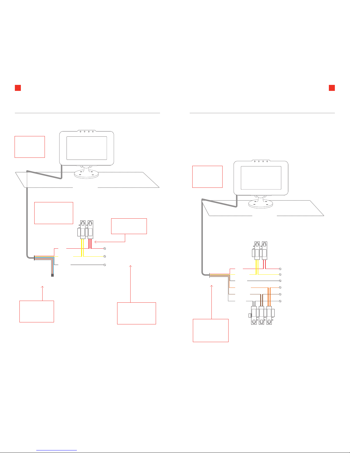
Wiring Diagram – Additional inputs
Dashboard
YELLOW
Switched
Power (Engine on/o)
Permanent Power (12V or 24V)
Ground
Digital input 2
Digital input 3
BLACK
ORANGE
BROWN
GRAY
RED
Digital input 1
3A
3A
3A
IGN
+ve
Any unused wiring
should be stored
neatly, insulated
and secured
Note: Ensure
wiring is neatly
routed to under
the dash
Dashboard
Wiring Diagram – Standard
YELLOW
BLACK
Permanent Power (12V or 24V)
Switched
Power (Engine on/o)
Ground
RED
IGN
+ve
Any unused wiring
should be stored
neatly, insulated
and secured
The switched input
is used to report on
engine running time
and idle time
Fuses must be fitted
at connection point.
This is to protect the
wire in case of a short
Cut wire loop and
connect fuse inline.
Note: Ensure
wiring is neatly
routed to
under the dash
RAM
RAM
EROAD
RAM
RAM
EROAD
• Additional connections are available for three digital inputs – orange, brown
and gray wires. If used, they must be fused individually using 3A fuses.
• Below is the connection diagram showing the additional input connections.
Example inputs include things such as PTO, lights, generator etc.
Page 7
10 11
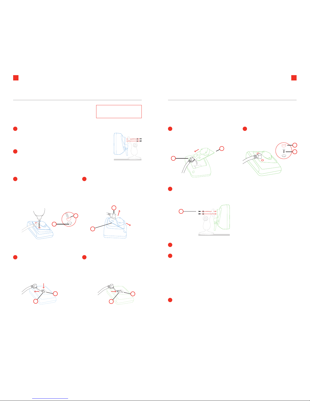
Replacement installation
NOTE: Turn o the engine
prior to replacing the Ehubo
Unpack the replacement Ehubo and also place it screen
down on a clean, flat surface.
Make sure to not scratch or damage the screen!
EXISTING EHUBO:
Push down the cable plug latch
to release the cable plug (J) and
carefully slide the cable plug o the
internal connector (K).
Mount the replacement Ehubo on the existing mount using the
screws and washers (C) supplied with the replacement Ehubo.
Remove the rear hatch of both, the
existing and the replacement Ehubo:
Remove the rear hatch security plugs
(F) by using a handheld battery
powered drill or similar. Unscrew the
rear hatch screws (G) on both units.
REPLACEMENT EHUBO:
Carefully insert the cable plug (J)
to the internal connector (K).
Make sure the cable plug latch clicks
into place to safely secure the plug.
Lift the rear hatch (H) o the
existing Ehubo and slide it o the
cable grommet (I). Lift the rear hatch
o the replacement Ehubo.
Insert the two rear hatch
screws (G) and new
security plugs (F).
Slide the replacement Ehubo’s rear
hatch (H) onto the cable grommet (I) and
insert it into the replacement Ehubo.
Remove the existing Ehubo from its mount and carefully
place it screen down on a clean, flat surface.
Make sure to not scratch or damage the screen!
1
2
3
5
4
6
Pull the sticker and screen protection film o the Ehubo screen.
Please place the uninstalled Ehubo in the replacement
box and return to EROAD including surplus parts.
Check and finalize the installation by following the instructions on the screen.
Once the install checks have been successfully completed, the Ehubo Home
screen will appear.
The install is now complete.
You are good to go!
Please remember to record the Ehubo’s serial number along with the vehicle ID
or number plate of the vehicle it is installed in and supply this information to an
administrator in the oce.
G
I
I
H
F
G
J
K
To replace an existing Ehubo, disconnect the power
cable from the existing Ehubo and connect it to the
replacement Ehubo by following these simple steps.
H
C
9
10
11
12
7 8
F
J
K
Page 8
12 13
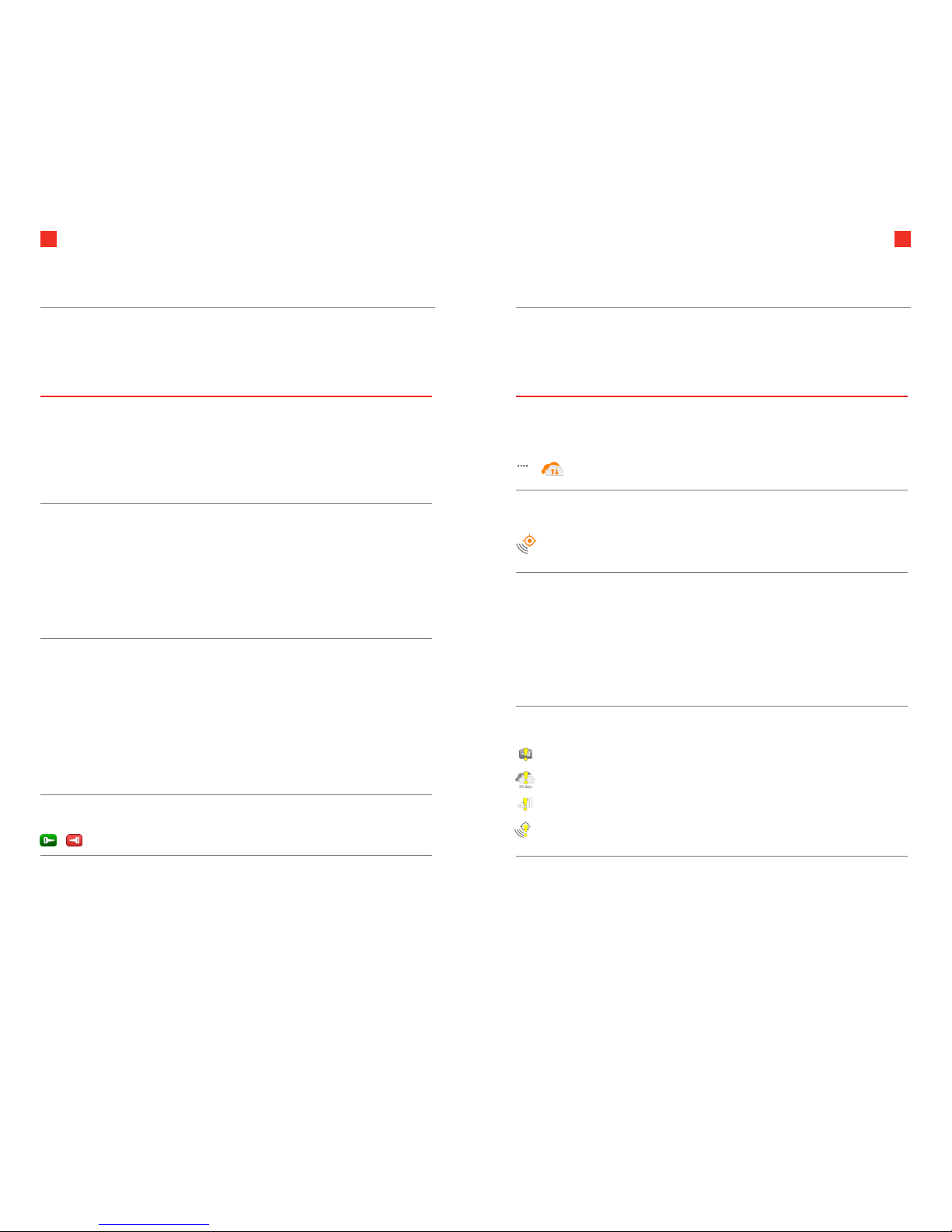
Troubleshooting
This section will provide some solutions if the installation of your Ehubo
is unsuccessful or the Ehubo doesn’t perform as expected.
3G
SCENARIO DETAILS SOLUTION
The Ehubo screen
remains black after
installation even if I
tap the screen
No connection to
permanent power
Ensure that the vehicle is stationary.
Check that the fuses have been
inserted properly.
Check that permanent power has
been properly connected to the
red wire.
Green power light on
top is o when driving
No connection to
permanent power
Check that the fuses have been
inserted.
Check that permanent power has
been properly connected to the
red wire.
Check that switched power has
been properly connected to the
yellow wire.
I can’t successfully
complete the install
checks
Permanent and/or switched
power connections
potentially incorrect.
Permanent power
connection point unable to
supply enough current to
the Ehubo.
Check that the fuses have been
inserted properly.
Check your wiring against the wiring
diagram and this manual.
Ensure that the permanent supply
connection point is capable of
supplying the Ehubo.
Ensure you have a good Ground and
power connection.
Engine on/o icon
shows incorrectly
Switched power incorrectly
connected
Check that switched power has
been connected to the yellow wire.
SCENARIO DETAILS SOLUTION
Icons indicate that the
Server Connection and/
or Cellular Connection
cannot be established.
The Ehubo needs to be in
cellular coverage to connect
successfully. It may take a
minute or two to connect
initially.
Ensure that your vehicle is in a
location with adequate cellular
coverage.
Icons indicate that GPS
reception is poor or
cannot be established.
A good view of the sky is
required for optimal GPS
operation. It may take a
few minutes initially to get
reception.
Reposition the Ehubo so it has a
good view of the sky.
Move the vehicle outside, away from
overhead obstructions.
The screen doesn’t turn
on when I tap it
You can only turn on the
screen when the vehicle is
stationary.
Ensure that the vehicle is stationary.
Check that the Ehubo has been
installed correctly.
Check that the fuses have been
inserted properly.
Check that permanent power has
been connected to the red wire.
One of the following
icons shows:
Faulty ignition
Faulty connection
Faulty SIM
Faulty GPS
Something is not
quite right.
Contact your supervisor
or employer
© 2015 EROAD. Doc 100200AB1.5. 05/2015.
By using this Ehubo you are agreeing to be bound by
EROAD’s Terms of Use that you can find at www.eroad.com.
Page 9

14
INNOVATION AND INTEGRITY
EROAD.COM
 Loading...