

Page 1
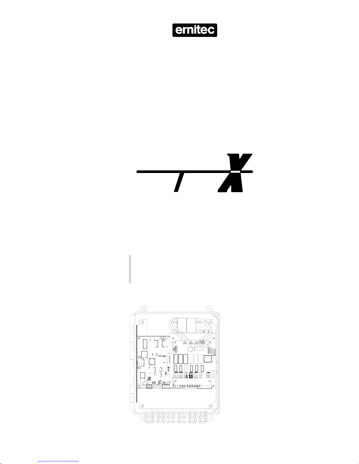
Variable Speed PTZ Receiver
R131VX
Installation
Manual
2852-00001
SYS E
M
Page 2

SYS
EM
2852-00001
Page 3

Introduction
The R131VX is a LONWORKS® telemetry receiver designed for driving a 24 VDC variable
speed pan & tilt head, a motorised zoom lens and six auxiliary functions operated via the
potential free relay contacts.
A 12 VDC power supply output for driving e.g. a camera is available as well as possible
fitting of an optional video transmission module; for twisted pair or optical fiber.
The R131VX features 128 pre-positions, four fully programmable pre-set tours, four privacy
zones, Auto-pan, Home-function, soft-limits, programmable lens drive voltage, tamper alarm
and selection of pan & tilt head brand and type.
All settings are selected remotely using the S111SX Node Manager - no on-board settings
are required or even possible.
Daily operation is carried out using the keyboards Series K111DX.
Validity
This manual cover the R131VX, serial number R131VX-000100 or higher.
Compatibility
The R131VX is compatible with any SYSTEM X component.
Any motorised lens with two individual wires per function driven by 6-12 VDC can be used,
however, to ease installation and for optimum Privacy Zone performance the use of the
Ernitec motorised zoom lenses Series Q is highly recommended.
The following DC pan & tilt heads are compatible:
v Ernitec MPT-5P
v Conway C2020
v Molynx Mustang PT12
v Shawley Prince 165
v Videmech 555P
Approvals
The R131VX is -certified and approved in accordance with the EU directives regarding
Electromagnetic Compatibility (EMC) and Low Voltage safety (LVD) with respect to the
EN 50081-1 (EMC, emission), the EN 50130-4 (EMC, immunity) and the EN 60950 (LVD,
safety) standards.
Warning: To fulfil the above regulations make sure to carefully follow the installation
instructions in this manual.
Trademarks
Echelon®, LON® and LONWORKS® are trademarks of Echelon Corporation registered in the
United States of America and other countries.
2852-00001 Page 1
SYS
EM
Page 4

Installation
All connections are shown on Figure 1 at the fold-out page at the back of this manual.
Carefully follow the instructions in order not to cause mal-function, damage to the
equipment or humans. Incorrect installation will void the warranty and repairs will
consequently be invoiced according to current scale charges.
All settings are selected remotely using the S111SX Node Manager - no on-board settings
are required or even possible.
Once all cable connections have been done installation is completed by activating the mains
switch. Prior to activating the mains switch make sure the S111SX Node Manager is running
and connected to the network.
If several R131VX units are present carefully note the exact time of mains switch activation this information is crucial when identification and configuration of each unit later is carried
out using the S111SX Node manager.
Warning: Self-test procedures, including moving the pan & tilt head to end-stops, are
initiated when the calibrate function is activated from the S111SX Node Manager. Make sure
all connections and adjustments, including setting the pan & tilt end-stops and/or limit
switches are made prior to activating the calibrate function.
Unpacking the unit
Check that the carton box contains the following items:
v R131VX unit
v Connector kit
v Box mounting kit
v Installation Manual (this manual)
Carefully check for any sign of damage. Any such damage or parts missing should be
reported to your supplier prior to installation.
Box installation
The box must be mounted on a plane surface to prevent the box from being twisted and
thereby become leaky. The box should be oriented with the cable glands pointing
downwards.
Fit the plastic mounting ears on the box. The mounting ears and screws are enclosed in the
box mounting kit.
Drilling pattern: 203 mm (width) x 329 mm (height). For further details refer to Figure 2 at
the back of the fold-out page.
Cable glands
All cables are fed through the cable glands. For each cable choose an appropriate sized
gland according to the table below close to the connector inside. Make sure to tighten the
glands properly. For further details refer to Figure 2 at the back of the fold-out page.
Cable diameter ø6-12 mmCable gland, Type 2
Cable diameter ø5-9 mmCable gland, Type 1
SYS
EM
Page 2 2852-00001
Page 5

Mains connection
Mains connection is located on the relay board, terminal J1.
The R131VX must be used with a 3-wire mains connection (2W+PE @ min. 0,75 mm2,
PE=yellow/green, neutral=blue).
Note: Terminals marked with hazardous live symbol requires installation by an
instructed person.
The wires must be secured to the Cable Anchoring Fingers on the board using a cable tie.
Each wire must be connected exactly as shown on the fold-out page drawing.
The unit is designed for continous operation.
Warning: Make sure correct mains voltage 230/115 VAC is selected with the voltage
selector S2 prior to activating the mains switch.
Mains voltage selector and mains fuse
Prior to connecting mains voltage make sure the correct nominal mains voltage 230VAC
(factory default position) or 115 VAC is selected with S2 located on the relay board.
The mains fuse F1 located on the relay board is factory set for 230 VAC operation. A fuse
suitable for 115 VAC operation is included in the connection kit.
Replace with same type and rating only; i.e.:
v 230 VAC: T500mA
v 115 VAC: T1A
LON® Network Installation
All SYSTEM X components (nodes) are connected together in a common LONWORKS
®
communication network.
The network is polarity insensitive and therefore either of the two twisted pair wires can be
connected to either of the LON® connectors on the SYSTEM X components.
Due to the risk of cross-talk/interference, it is recommended not to run LON
®
Network cables
close to high voltage cable, or cables carrying video signals.
In countries where the CE approval is mandatory, LON
®
cables with an overall
screen must be used in order to comply with EMC/EMI standard EN 50130-4.
The cable screen should be connected to the cable clamp next to the LON
®
connector.
2852-00001 Page 3
SYS
EM
Page 6

Selection of network Topology
In a free topology network, there are no demands as to how the cables are routed
between the nodes. It can be point-to-point, bus, star, tree, or a mixture.
Free Topology
Termination
When using free topology, the maximum cable length in one segment is approx. 500 meters,
and is calculated adding together all cables used. The maximum number of nodes in one
segment is 64. If more that 500 meters, or more than 64 nodes, is required, two or more
network segments can be made, using a repeater between each segment.
Bus Topology
In a bus topology network, all nodes are connected on a bus. Cable stubs can be used to
connect the individual nodes to the bus, as long as the length of the stub is maximum 3
meters. The advantage of bus topology, is that the cable length can be longer than when
using free topology. This can be useful e.g. when making network connection to remote PTZ
cameras.
Bus Topology
Termination Termination
The maximum number of nodes on one bus is 64. Maximum length of the network bus
depends on the type of cable used. If more nodes, and/or longer cable length, is required,
two or more network segments can be made, using a repeater between each segment.
Termination
Each network segment require termination for proper data transmission performance. The
type of termination varies depending on whether Free topology or Bus topology is used.
In a free topology network segment, only one termination is required and may be placed
anywhere on the network. The termination resistor should be a 52 Ω, 1/4W type.
In a bus topology network segment, two terminations are required, one at each end of the
bus. The termination resistors should each be a 105 Ω, 1/4W type.
Termination resistors, which are included with the SYSTEM X keyboard, are easily fitted using
the LON® connectors on the SYSTEM X units as shown below.
SYS
EM
Page 4 2852-00001
LON® cable
Termination
resistor
Page 7

Repeater
If the maximum numbers of nodes (max. 64) or total cable distance are exceeded, a repeater
can be added to interconnect two or more network segments.
A repeater can also be used to convert from a free topology network to a bus topology
network. This can be useful when e.g. making network connection to remote PTZ cameras.
Note that only one Repeater should be placed in series between any two nodes in a segment
Bus Topology
Termination Termination
Free Topology
Termination
3-way
Repeater
Free Topology
Termination
LON® Network Cables
The following five cables/cable types have been validated by Echelon
®
, but other cables may
be used provided they have specifications similar to the ones listed below:
Anixter 4QJB2
5)
Coferro J-Y(St)Y
5)
Waschek 240208
5)
Eupen J-Y(St)Y Lg
5)
Yes0,8mm20,4AWGJ-Y(St)Y3) 2x2x0.8
Anixter 9F220154
5)
Available0,65mm22AWGLevel IV2) cable
-No1,3mm16AWGBelden 85102 (Tefzel jacket) or equivalent
-No1,3mm16AWGBelden 8471 (PVC jacket) or equivalent
Belden 1624
5)
Belden 1633A
5)
Belden 1668A
5)
Available0,5mm24AWGTIA/EIA 568A1) Category 5 cable
ExamplesShield
4)
DiameterAWGValidated Cables and Cable Types
1)
Any cable that meets the TIA/EIA 568A standard, is suitable for LON® Networks.
2)
Standard originally specified by the National Electrical Manufacturers Association (NEMA).
3)
The J-Y(St)Y cable is normally only available in Europe.
4)
In order to comply with EMC/EMI standard EN 50130-4, shielded cable must be used.
5)
With shield.
A list of cable suppliers can be found in e.g. the K111DX Keyboard X manual
.
2852-00001 Page 5
SYS
EM
Page 8

LON® Network Cable Lengths
900 meters320/500 metersJ-Y(St)Y 2x2x0,8
1400 meters400/500 metersLevel IV
2700 meters500/500 metersBelden 85102
2700 meters400/500 metersBelden 8471
900 meters250/450 metersTIA/EIA 568A Category 5
Bus Topology
Max. Total Length
Free Topology
Max. Node-to-Node/Total Length
Cable type
Junction Boxes
When splicing/terminating cables in the LON® Network installation, the following methods are
normally used:
A Pass-Thru Junction Box is used to splice two cables. No SYSTEM X nodes or connectors
are provided at a pass-thru junction box.
Pass-Thru Junction Box
LON Network
LON Network
A Stub Junction Box is used to splice two cables and provide a stub for servicing a local
SYSTEM X node.
Stub Junction Box
LON Network
LON Network
To local node
A local Loop Junction Box is used to terminate two cables, and provide a wiring loop for
servicing one, or more, local SYSTEM X nodes.
Loop Junction Box
LON Network
LON Network
Local loop
SYS
EM
Page 6 2852-00001
Page 9

Pan & tilt head connection
Connections are shown on the fold-out drawing.
Do not use other heads than specified in the Compatibility section. The actual pan & tilt
head type is set using the S111SX Node Manager.
Cables should be kept as short as possible and should not exceed 5 meters. When installed
in areas where interference may be present, such as close to high-voltage cables,
transformers, heavy duty motors, electrical trains, radar or radio transmitters, including GSM,
GPRS, cell phone, DECT or similar digital mobile phone base antennas, shielded cable should
be used. Cable shield should be connected to the X5-5 terminal.
In general it is recommended to run the feed-back potentiometer wires, i.e. the wires
connected to X5 in a separate shielded cable, for optimum preset performance.
Motorised lens connection
Connections are shown on the fold-out drawing.
Any motorised lens with two individual wires per function driven by 6 to12 VDC can be
used, however, to ease installation and for optimum Privacy Zone performance the use of the
Ernitec motorised zoom lenses Series Q is highly recommended. Lens drive voltage is set
using the S111SX Node Manager.
Cables should be kept as short as possible and should not exceed 5 meters.
When installed in areas where interference may be present, such as close to high-voltage
cables, transformers, heavy duty motors, electrical trains, radar or radio transmitters, including
GSM, GPRS, cell phone, DECT or similar digital mobile phone base antennas, shielded cable
should be used. Cable shield should be connected to the X3-5 terminal.
AUX-connection
Six auxiliary functions can by operated via the AUX1 to AUX6 relays located on relay board.
The relay contacts are potential free and may be loaded with maximum 230 V, 5 A.
Note, that the relay contacts are un-fused. High voltage wires must be secured with cable
ties to the Cable Anchoring Fingers located on the edge of the board. Cable ties are not
included.
Camera power supply
A fully regulated 12 VDC output with a maximum load of 800 mA for driving e.g. a camera
is available. Connections are shown on the fold-out drawing. The output is over-load
protected.
Other connections
An optional video transmission module for twisted pair or fiber optical cable may be fitted in
the R131VX. Refer to the manual supplied with the module for installation instructions.
Connections X6-1 & 2 and connector J2 are reserved for internal use within Ernitec only.
All jumpers/pin-headers are factory set and should not be altered.
Warning: Do not make any connections to X6-1 or X6-2 and J2. All jumpers/pin-headers
are factory set and must not be altered.
2852-00001 Page 7
SYS
EM
Page 10

Mains switch activation
Once all cable connections have been done installation is completed by activating the mains
switch. This will identify the unit on the network. Prior to activating the mains switch make
sure the S111SX Node Manager is running and on-line to the network.
Warning: Make sure correct mains voltage 230/115 VAC is selected prior to activating the
mains switch.
Note: If several R131VX units are present carefully note the exact time of activation of the
mains switch - this information is crucial when identification and configuration of each unit
later is carried out using the S111SX Node manager.
Push-buttons
Pressing S1
LONW
ORKS® Service Pin will identify the unit on the network, just as when the
mains switch is activated. Prior to pressing the Service Pin S1 make sure the S111SX Node
Manager is running and on-line to the network.
The S2 Start/Stop and S3 Choose push-buttons are reserved for future applications and
should not be activated.
SYS
EM
Page 8 2852-00001
Page 11

Fault finding guide
If the quide below suggests new configuation use the S111SX Node Manager to configure
the unit.
No operation possible
v If green “RUN CPU” LED H2 is off check mains fuse F1 located on
the relay board. The unit is also equipped with resettable overload
components - disconnect from mains supply and allow the unit to
cool down for a few seconds.
v If yellow “LON” LED H1 is on or blinking the unit is unconfigured.
v Check the network cable connections and network termination.
No or intermediate Pan- and/or Tilt operation
v Check that the unit is configured for the actual pan & tilt head.
v Check the wiring for short-circuits or broken wires.
v If one function only is failing try to swap the pan and tilt wiring to
determine the fault location. If e.g. the tilt initially was faulty
connect the tilt wires to the pan output and try to operate the tilt
by activating the pan function. If inoperative still the pan & tilt
head is faulty - if operative now the output is overheatet or
defective.
v The outputs are overload protected - disconnect from the mains
supply and allow the unit to cool down for a few seconds.
No or slow Zoom- and/or Focus operation
v Check the wiring for short-circuits or broken wires.
v If one function only is failing try to swap the zoom and focus
wiring to determine the fault location. If e.g. the zoom initially
was faulty connect the zoom wires to the focus output and try to
operate the zoom by activating the focus function. If inoperative
still the lens is faulty - if operative now the output is overheatet or
defective.
v If running too slow or fast reconfigure the lens setup.
Pre-positions cannot be found, are in-accurate or drifting
v Check the wiring for short-circuits or broken wires. Check
feed-back potentiometers fitted in the pan & tilt head and lens
electrically and mechanically. Note, that most potentiometers
wear out in 4-18 months if used on a 24-hour tour basis.
v Cables are too long or exposed to excessive noise. Refer to the
Pan & Tilt head connection section for possible solutions.
2852-00001 Page 9
SYS
EM
Page 12

Technical specifications
TP/FT Free- or Bus-topology
LONW
ORKS® Communication interface
278 x 318* x 267 mm / 5,2 kgDimensions (X x Y*x Z ) / Weight (*excl. glands)
EN 50081-1 , EN 50130-4 / EN 60950CE-approvals (EMC / LVD)
12 VDC, 800 mAPower supply output (fully regulated)
230 V, 5 AAUX-relays, max. load (unfused)
<1°Pre-position accuracy with Ernitec MPT-5P pan & tilt head
-15° to +55° CelciusTemperature range
IP65 / UL 94-5VEnclosure (protection / fire), glass-fiber reinforced polyester
155 mA @ 230 VAC, 310 mA @ 115 VACCurrent consumption
115/230 VAC, ± 10%, 45-60 HzMains voltage, selectable
SYS
EM
Page 10 2852-00001
HEAD OFFICE: ERNITEC A/S, HØRKÆR 24, P.O. BOX 720, DK-2730 HERLEV, DENMARK
TELEPHONE: +45 44 50 33 00, TELEFAX: +45 44 50 33 33
HOMEPAGE: http://www.ernitec.dk, E-MAIL: ernitec@ernitec.dk
UK OFFICE: ERNITEC UK, GERRARD HOUSE, WORTHING ROAD, EAST PRESTON, WEST SUSSEX BN16 1AW, ENGLAND
TELEPHONE: 01903 77 27 27, TELEFAX: 01903 77 27 07
E-MAIL: sally@ernitec-uk.co.uk
GERMAN OFFICE: ERNITEC GmbH., STORMARNRING 28, 22145 STAPELFELD, GERMANY
TELEPHONE: (040) 6756 25 0, TELEFAX: (040) 67 56 25 25
E-MAIL: ernitec@aol.com
FRENCH OFFICE: ERNITEC FRANCE,
N° 29
PARC CLUB DU MILLENAIRE, 1025 RUE HENRI BECQUEREL, 34036 MONTPELLIER CEDEX 1, FRANCE
TELEPHONE: (4) 67 15 10 15, TELEFAX: (4) 67 64 01 81
E-MAIL: ernitec@ernitec.fr
MIDDLE EAST OFFICE: ERNITEC ME, HAMRA-MAKDESI STR., YOUNIS CENTER-5th FLOOR, OFFICE NO. 503
P.O. BOX 113/5721, BEIRUT, LEBANON TELEPHONE: +961 1 751 796, TELEFAX: +961 1 751 795
HOMEPAGE: http://www.ernitecme.com, E-MAIL: malek_kabrit@ernitecme.com
 Loading...