

Page 1

Digital Video Recorder
Series EDNS4000
Series EDNS6000
Series EDNS7000
4-8-16 camera system
3040-0079
Page 2

DigiOp Installation Manual
Page 2 of 115
Table of Contents
4-8-16 camera system...............................................................................................................................1
3040-0079Table of Contents....................................................................................................................1
Table of Contents.....................................................................................................................................2
Introduction to Digital Video Recording .................................................................................................7
DigiOp Four Times Compression Efficiency.......................................................................................7
DigiOp provides Triplex on Remote....................................................................................................7
Main features of DigiOp ..........................................................................................................................7
Highly reliable maintenance-free Digital Security System..............................................................7
Fully compatible with existing CCTV Cameras and Equipment .....................................................7
Innovative Enhanced MPEG Compression Technology..................................................................7
High-speed search and clear printing...............................................................................................7
You can use a maximum of 16 CCTV Cameras at the same time...................................................8
Manipulation and alteration of recorded images are impossible as DigiOp uses Propr ietary
Authentication .................................................................................................................................. 8
Real-time image transmission through the Internet .........................................................................8
What is DigiOp RemoteManager? ...................................................................................................8
Getting Started with DigiOp ..................................................................................................................10
Warning.......................................................................................................................................12
Cautions.............................................................................................................................................13
Important Safeguards .........................................................................................................................13
1. INTRODUCTION..............................................................................................................................15
Differences between “Real-time” Display and Normal Display........................................................15
2.0 DVR SYSTEM STRUCTURE AND INSTALLATION ......................................................15
2.1. Getting Started.........................................................................................................................15
2.2 Camera and Audio input connection leads .........................................................................15
3.0 Reset and Power Buttons........................................................................................................17
Reset Button:..................................................................................................................................17
Power Button: .................................................................................................................................17
Auto-recovery: ...............................................................................................................................17
3.1 EDNS4000 Hardware layout ..................................................................................................19
3.2 EDNS6000 Series Hardware layout .......................................................................................21
3.3 EDNS7000 Series Hardware layout .......................................................................................21
3.3 EDNS7000 Series Hardware layout .......................................................................................22
4.0 Installation DigiOp DVR ..........................................................................................................22
4.0 Installation DigiOp DVR ..........................................................................................................23
4.1 Connections ............................................................................................................................23
4.2 Typical System connection diagram..........................................................................................24
4.3 System Installation considerations and notes:........................................................................24
5.0 Turning “ON” the DigiOp DVR ......................................................................................................26
5.1 Logging In..........................................................................................................................26
5.1.1 Users:..............................................................................................................................26
5.1.2 RemoteManager Users ...................................................................................................28
5.2 Shutting down the DigiOp DVR ........................................................................................28
Page 3

DigiOp Installation Manual
Page 3 of 115
5.3 Abnormal shut down or restart procedures........................................................................29
6.0 System Operations......................................................................................................................30
On-screen keyboard........................................................................................................................30
CONFIGURE MENU – available options.........................................................................................30
Auto log off ....................................................................................................................................31
Using RemoteManager or other integrated remote applications....................................................31
Main screen............................................................................................................................................32
On-screen information: ......................................................................................................................32
On-screen control functions: ..............................................................................................................34
Switching between multi-image screen and single-image screen. .....................................................36
TOOLS button .....................................................................................................................37
DVR Configuration Menu Options:.......................................................................................................37
CAMERA Tab: ......................................................................................................................................38
Video input status and selection.....................................................................................................38
Camera identification .....................................................................................................................38
Recorded View ...............................................................................................................................39
Recorded video quality...................................................................................................................39
Security Screen Mode ....................................................................................................................39
Watch Mode ...................................................................................................................................40
Simple Recording Time Schedule ..................................................................................................40
Motion Detection Area...................................................................................................................40
Motion Detection Sensit ivity.........................................................................................................41
Motion Sensitivity “quick start” guidelines .......................................................................................42
Network Tab ...........................................................................................................................................43
Enabling network connectivity...........................................................................................................43
Network Settings (EDIT)...............................................................................................................43
Network Adaptor List .....................................................................................................................44
IP Address......................................................................................................................................44
Gateway..........................................................................................................................................44
DNS................................................................................................................................................44
Additional Network Options ..............................................................................................................45
Bandwidth Throttle or Bandwidth Limit ........................................................................................45
Time Synchronization....................................................................................................................45
Ensure DigiOpTS.exe runs whenever the PC is started.....................................................................46
Remote Connection Settings ..............................................................................................................47
Remote Users .................................................................................................................................47
Remote Event Notification.................................................................................................................48
Remote Connection Time Limit – refer Event Notification list .........................................................48
Auto Disconnect on no activity after: ............................................................................................48
Connection Time Limit ..................................................................................................................48
Transmission Time Limit – on Sensor activation. .............................................................................49
Sensor and Control tab ...........................................................................................................................50
Enabling the Sensors and Controls.................................................................................................50
Associating Sensors (inputs) to create an action............................................................................51
Causing a Camera(s) to record on a Sensor trigger ........................................................................51
Causing a Sensor trigger to move a camera to a pre-defined PTZ position...................................52
Page 4

DigiOp Installation Manual
Page 4 of 115
Causing a Sensor trigger to activate a Camera and a Control (output relay).................................52
Sensor Type....................................................................................................................................53
Sensor Alarm..................................................................................................................................53
Sensor Recording Time..................................................................................................................53
Sensor 4 input used for shut down.................................................................................................53
Video Loss Detection.....................................................................................................................54
Recording failure Alarm.................................................................................................................54
Display mode freeze after sensor...................................................................................................54
Motion Sensor................................................................................................................................55
Pre-alarm record period..................................................................................................................55
Recording Mode – Normal or Optimized ......................................................................................56
PTZ Tab ..............................................................................................................................................57
Typical PTZ wiring........................................................................................................................58
Enable PTZ.....................................................................................................................................58
PTZ Protocol..................................................................................................................................59
PTZ Protocol..................................................................................................................................59
Adding a Protocol...............................................................................................................................59
PTZ Camera Address.....................................................................................................................60
Set up procedure.................................................................................................................................61
Preset ..................................................................................................................................................62
SET.................................................................................................................................................62
LOCATION ...................................................................................................................................62
MOVE ............................................................................................................................................62
Color Tab ................................................................................................................................................63
DISPLAY Tab........................................................................................................................................65
Enable/Disable Camera Recording ....................................................................................................65
Password Protected Recording...........................................................................................................66
User Management ..............................................................................................................................66
Add, Delete, Modify User Profiles .....................................................................................................67
Export and Import User Profiles ........................................................................................................68
External Monitor................................................................................................................................68
Recording Resolution.........................................................................................................................69
Frames per second ..............................................................................................................................70
Compression type...............................................................................................................................70
Video ..............................................................................................................................................70
Audio Quality.................................................................................................................................70
Retain Video Data ..............................................................................................................................71
Display Division.................................................................................................................................71
Adding a sequence .........................................................................................................................72
Modify or Clear a sequence ...........................................................................................................72
Default............................................................................................................................................72
Display Division Rotation Dwell Time ..............................................................................................73
FPS/Resolution tab.................................................................................................................................74
FPS Settings per Camera (by Resolution). .........................................................................................74
Allocating FPS and Resolution to each camera .................................................................................75
Schedule tab ...........................................................................................................................................76
Page 5

DigiOp Installation Manual
Page 5 of 115
To create a schedule for a camera ......................................................................................................76
To define the time on a schedule ....................................................................................................77
Recording modes............................................................................................................................77
To Adjust FPS by Schedule (global)..............................................................................................78
To EDIT a defined schedule. ..........................................................................................................79
To DELETE a defined schedule.....................................................................................................79
To restore the list to the default setting..........................................................................................79
Defining a HOLIDAY for the Schedule ............................................................................................79
System Tab.............................................................................................................................................80
Upgrading Software ...........................................................................................................................80
Disk Full Notification.........................................................................................................................81
Send a Relay Output every 5 minutes to:.......................................................................................81
Show Warning in every 5 minutes. ................................................................................................81
System Backup ...................................................................................................................................82
Reset Configuration - Reset to Default. .............................................................................................82
Export/Import System Configuration.................................................................................................82
Email Notification..............................................................................................................................83
Select Events......................................................................................................................................83
Example: Setting up the SYSTEM EVENTS for Email Notification............................................84
Example: Setting up the SYSTEM EVENTS for Email Notification............................................85
Search.....................................................................................................................................................86
Graphical Record Log ........................................................................................................................87
Scan Bar (quick search cursor line) ................................................................................................87
Current Date and Time.......................................................................................................................87
Search record Date and time ..............................................................................................................88
Camera selection and camera list scrollbar ........................................................................................88
Playback Controls ..............................................................................................................................88
Playback speed control.......................................................................................................................89
Screen division display modes ...........................................................................................................89
Still Image Zoom button....................................................................................................................89
Interlace/De-interlace button..............................................................................................................90
Save Searched Images Button............................................................................................................91
Video Backup Button.....................................................................................................................91
Still Image Backup (BMP or JPG).....................................................................................................92
Standard Format – MPEG Video Backup (minutes)..........................................................................92
SEARCH TOOLS menu ....................................................................................................................93
Image Adjust......................................................................................................................................93
POS (Point of sale).............................................................................................................................93
Configure............................................................................................................................................94
Add Printer .........................................................................................................................................94
Search Option.....................................................................................................................................94
Volume Control..................................................................................................................................94
Search Sensor Events.........................................................................................................................95
Print ....................................................................................................................................................95
Hour Backup ......................................................................................................................................96
Smart Search..........................................................................................................................................97
Page 6

DigiOp Installation Manual
Page 6 of 115
View Search Process (during SmartSearch).......................................................................................99
Sensitivity (for SmartSearch).............................................................................................................99
SmartSearch - Search.........................................................................................................................99
Quick Search......................................................................................................................................99
Start the SmartSearch Process..........................................................................................................100
Search Next Movement ................................................................................................................100
Stop Search...................................................................................................................................100
SmartSearch Result Event List .........................................................................................................101
Zoom (for playback only) ................................................................................................................101
Post Processing of recorded images .................................................................................................102
Image enhancement option buttons ..................................................................................................103
Recorded and Preview Images .........................................................................................................104
User-Defined Enhancement Settings ...............................................................................................105
Image Post Processing Save, Print, Copy........................................................................................106
Exit Application (Exit to Windows) .....................................................................................................107
Windows START menu ...................................................................................................................107
Programs running (tray icons)..........................................................................................................107
NetBackup Agent .............................................................................................................................108
Hard Drive Configuration................................................................................................................109
DigiOp C:\ Drive..............................................................................................................................109
DISSTECH D:\ Drive.......................................................................................................................109
DTA E:\ Drive..................................................................................................................................110
SYS F:\ Drive...................................................................................................................................110
DISSTECH G:\ Drive.......................................................................................................................110
Unlabelled Drive ..............................................................................................................................110
Other Drives .....................................................................................................................................110
Disconnecting USB devices .............................................................................................................110
Registration details...............................................................................................................................111
MRC and License Numbers .............................................................................................................111
Software Version and Hardware Version.........................................................................................111
File naming conventions ......................................................................................................................112
Block Diagram for Alarm I/O ..............................................................................................................114
EDNS4000 I/O Connections on 15 pin DIN connector ...................................................................114
TCP/IP Port setting method using the firewall.................................................................................115
Page 7

DigiOp Installation Manual
Page 7 of 115
Introduction to Digital Video Recording
Rapid economic growth and commercial sophistication in recent years has made protection
of major facilities and intellectual property a critical issue for businesses and individuals. The
demand for the centralized management of security systems and controls, as well as
protection of property from fire hazards and other natural disasters, using remote
surveillance systems is growing at an accelerating rate.
DigiOp Four Times Compression Efficiency
By using its e nhanced MPEG format, file compression algorithm, the manufacturer of the
DigiOp DVR systems, General Solutions Ltd, has improved file compression efficiency over
conventional methods. DigiOp DVR’s can record and store digital images for much longer
periods of time as compared to competitive technologies.
DigiOp provides Triplex on Remote
Main functions of digital security can be classified into three categories: Image recording,
Multiplexing, and Data transmission for remote surveillance. By combining all three functions
into a single, easy to use system, DigiOp can fully meet user requirements and achieve a
more effective security solution than ever before.
Main features of DigiOp
Highly reliable maintenance- free Digital Security System
Images stored on videotapes are often distorted from prolonged use, and clear still images
are virtually impossible to obtain. But DigiOp uses a digital method to store images on the
hard drive so the still image is clear when printed. As a result of this storage method, DigiOp
can save you money in maintenance costs because you can record images over and over
again on the same drive.
Fully compatible with existing CCTV Cameras and Equipment
DigiOp is fully compatible with conventional CCTV cameras with PAL (or NTSC) signal,
which means no additional costs from having to replace an existing VCR, Multiplexer, or
other hardware.
Innovative Enhanced MPEG Compression Technology
Previously, only Motion-JPEG or MPEG were used. The Motion-JPEG has a disadvantage of
having large image files, so the image blurs when there is a lot of movement. But DigiOp
uses enhanced MPEG formats to improve the compression and image quality.
High-speed search and clear pr inting
High-speed search functions, recorded data manipulation, post-recording image
enhancement and SmartSearch are now a standard feature across the range of the
Page 8

DigiOp Installation Manual
Page 8 of 115
commercial DigiOp DVR’s. Using a compatible printer of your choice, you can produce the
clearest of printed images.
You can use a maximum of 16 CCTV Cameras at the same time
A DigiOp system can record a maximum of 16 CCT V camera images. Because the hard disk
capacity can be easily expanded, images of multiple channels can be recorded for longer
periods.
Manipulation and alteration of recorded images are impossible as DigiOp uses
Proprietary Authentication
Conventional systems use a standardized storage method which allows access and
manipulation of stored data information.
DigiOp uses proprietary encryption to protect files from unauthorized manipulation and
alteration, assuring that video is authentic. Original recordings are encrypted so images can
only be viewed by using the DigiOp decoder in DigiOp Viewers or the DigiOp plug-in for
Windows Media Player. Using DigiOp, images can also be converted to other video formats.
Real-time image transmission through the Internet
DigiOp uses a unique, enhanced, and encrypted MPEG compression algorithm and provides
the DigiOp “RemoteManager” software to transmit encrypted real-time images through the
Local Area Network or over the Internet.
What is DigiOp RemoteManager?
DigiOp RemoteManager was developed by the General Solutions Ltd software development
team and is provided with the DigiOp DVR Series. RemoteManager is a remote surveillance
software application which allows the operator to monitor DigiOp DVR camera images from a
number of remotely located DigiOp DVR’s using TCP-IP transmission. The operator has full
access to camera and DVR set-up without having to be at the DVR location. This is great for
centralized monitoring and provides flexibili ty/mobility for the user on the move. Remote
Manager enables the user to view up to 24 individual camera images at a time, pick and
choose which cameras are to be displayed (and where on the screen they will be displayed) ,
and connect and disconnect cameras from view at will.
Page 9

DigiOp Installation Manual
Page 9 of 115
Caution while installing DigiOp DVR
Please adhere to the following instructions to prevent damage, electrical fire, shock, personal
injury or equipment malfunction.
Warning
o Before connecting the power, double check the power switch (AC110V ~ 120V ->115,
AC220V~240V->230V) is switched to 230VAC.
o Do not pull on or place heavy items on the power cord.
o Connect directly to an approved electrical outlet source.
o Failure to connect properly may result in electric shock or fire hazard.
o Do not operate around water or other liquids.
o Prevent water, or other liquids, from contact with enclosure or electrical parts.
o Allow only certified technicians to install the product.
o Consult your authorized installer when the need for alterations or re-installation arises.
Improper installation may cause malfunction, electric shock, or fire hazard.
o Consult your authorized installer if special installation is required.
o “Earth” or “Ground” applies to video products equipped with a 3-wire earthing or
grounding plug having a third pin. This plug only fits into a grounding-type power
outlet. Improper grounding may cause malfunction or electric shock.
o Ensure that the camera system is properly grounded using methods defined in the
manufacturer’s specifications and instruction s. This will increase protection from
voltage surges and static. Failure to ground the entire system properly may cause
malfunction, electric shock, or built-up static charges.
o Do not dismantle or re-configure the system on your own.
o Failure to have the system properly maintained and serviced may cause malfunction,
void the manufacturer warranty obligations, and increase the risk of electric shock or
fire.
o Consult your authorized dealer before servicing the unit.
o Do not place hands or foreign objects over, on, or close to the air circulation and
ventilation on the unit.
o Do not remove the power cord from the unit to power down. If you want to turn the
DigiOp DVR off, either shut down using the software or press the power button on the
front panel (refer to installation manual for options and procedures).
Page 10

DigiOp Installation Manual
Page 10 of 115
Getting Started with DigiOp
DigiOp is designed for easy installation and use. This page shows how to install the DigiOp
system and explains the basic order of operation. Use this manual for clarification on any
point.
1. Connect all external cables and devices
2. Power up DVR – the DVR will auto sense all cameras and start recording (motion
detection mode).
3. Right click on the main screen, the Login button appears. Click and enter the default
Administrator password (e.g. User: admin Password: dg2ad33)
4. The TOOLS button will appear. Click TOOLS>PAUSE RECORDING.
5. A warning message will appear notifying that recording will be paused (click OK).
6. Click on the TOOLS>CONFIGURE menu option.
Page 11

DigiOp Installation Manual
Page 11 of 115
Digital Video Recorder
EDNS4000 (4-8-16 camera system)
EDNS6000 (16 camera system)
EDNS7000 (16 camera system)
DigiOp Digital Video Recorder Installation,
Programming, and User Manual
Page 12
DigiOp Installation Manual
Page 12 of 115
Warning
Electric Safety
To reduce risk of fire, or electrical shock, do not expose this product to liquids, rain or
moisture. Locate in a controlled environment.
Before connecting the power, double check the power switch (AC110V ~ 120V ->115,
AC220V~240V->230V) is switched to 230VAC.
Caution
Lithium Battery inside!!
There is the danger of explosion if battery is incorrectly replaced.
Replace only with the same type, or equivalent, recommended by the manufacturer.
Dispose of used batteries according to the battery manufacturer instruction.
Page 13

DigiOp Installation Manual
Page 13 of 115
Cautions
CCaauuttiioonn aanndd WWaarrnniinngg SSiiggn
n
This sign indicates that the user could be seriously or fatally injured if not
handled or installed properly.
Important Safeguards
Warning
1. Check power supply voltage setting before connecting power cord.
2. Before connecting the power, double check the power switch (AC110V ~ 120V ->115,
AC220V~240V->230V) is switched to 230VAC.
3. Use the power cord, which is supplied or recommended by the supplier. Must include
an earth connection.
4. Do not dismantle or open the equipment.
5. Do not touch the product with wet hands.
6. Equipment must be installed by a trained professional.
7. Equipment must be installed into a controlled, dry, clean and secure environment.
8. Prevent metallic, foreign or liquid substances from getting inside the product. This
includes insecticide or flammable cleaning spray.
Caution
1. Use the power cord that is supplied or recommended by the supplier.
2. Do not drop. Protect the equipment from vibration or sudden impacts.
3. Air is circulated throughout the unit. Ensure there is clean uninhibited air flow round
the equipment.
4. Ensure the temperature is maintained. Excessive internal temperature can harm the
system.
5. Ensure appropriate lightning, mains filtering and UPS are used in areas where th e
power source is susceptible. Damage through lightning, power source fluctuations,
spikes, etc. is not covered by warranty.
6. Install the system in a stable and level location
Page 14

DigiOp Installation Manual
Page 14 of 115
Caution about the Power
Warning
1. Before connecting the power, double check the power switch (AC110V ~ 120V ->115,
AC220V~240V->230V) is switched to 230VAC.
2. Do not turn of f the power by pulling the power plug out. To turn off the power, click the
power button on the front panel. When the system stops abnorm ally the power button
might not work, in which case you should press and hold the power button for at least
4 seconds.
3. Do not cut off the power or move the unit when hard drives are operating. Doing so
may cause damage and loss of data.
Page 15

DigiOp Installation Manual
Page 15 of 115
1. INTRODUCTION
Differences between “Real-time” Display and Normal Display
“Real-time” display units, EDNS6000 and 7000, provide the user real-time video viewing on
the DigiOp DVR server unit at the full 25fps per channel.
The normal units display the images at the rate of the recording; they could be considered
WYSIWYG – “what you see is what you get”.
The implications are:
• if using motion detection, the screen image will be the last recorded image. Minor
scene activity, or motion outside the trigger threshold, could be present but the image
may not update.
• if the unit is paused, the images on the screen may be replaced with the default
“splash screen” graphic. On the next motion detection event, the “splash screen”
graphic will be replaced with the moving video as the DVR starts recording.
2.0 DVR SYSTEM STRUCTURE AND INSTALLATION
2.1. Getting Started
Keep the packaging for transportation or storage purposes.
If any of the following items are missing or damaged, notify your supplier immediately.
The following accessories are supplied with each DigiOp Digital Video Recorder:
Digital Video Recorder
Packaging
Quick Start Guide
System Recovery CD Software
Mouse
Video/Audio Cables
Sensor/Relay adaptor (DIN connector - where applicable)
Cabinet key (where applicable)
2.2 Camera and Audio input connection leads
DigiOp DVR camera and audio inputs are either built-in type input connectors mounted
directly to the rear of the DVR , or use flexible multi-connection cables terminated with a multi
pin DIN plug and BNC connectors.
The Multi-connector cables come in a variety of formats that are typically suited to a
specific DigiOp DVR model.
Video or video/audio
connection cabling
Page 16

DigiOp Installation Manual
Page 16 of 115
o When installing these cables be very careful not to bend the interconnecting pins on
the cable plug and DVR.
o Do not pull or place undue stress on the cables or connectors when installing or
disconnecting the cables or camera cables.
o Multi-connection cables MAY include both video and audio inputs. The connectors are
labelled V = Video or A = Audio.
o Do not plug video sources into audio inputs or vice versa.
Page 17
DigiOp Installation Manual
Page 17 of 115
3.0 Reset and Power Buttons
Note: DigiOp DVR systems are designed to automatically start (Auto-Rebooting) soon after
power is supplied.
Reset Button: When the system is shut down abnormally, the reset button must
be pressed for at least more than one second to restart. The HDD
auto-recovery system operates, restoring the system with the last
system backup version of software. * Backup your system after
each system change.
Power Button: To shut down manually during system operation, the power button
must be pressed and held for at least one second. The monitor
displays ‘System Shutdown’ message and shuts down.
Auto-recovery: In case of abnormal operation, shut down the DVR by pressing
and holding the POWER button for at least four seconds. The
HDD auto-recovery system will restore system back to the
previous state.
Power Connection: Connect the power cord.
CAUTION
Before connecting the power, double check the power switch
(AC110V ~ 120V ->115, AC220V~240V->230V) is switched to
230VAC.
Mouse connection: Connect the mouse provided or a Windows compatible mouse.
LAN Port In case of remote monitoring, connect the LAN cable in the RJ-45
jack connector. Network has to be LAN (Local Area Network),
Internet, or exclusive line of TCP/IP based 10/100BASE-TX
Ethernet.
USB Connect exterior USB interface devices including hard drives, CDRW,
memory stick adaptors, etc. (Only approved USB CD-RW models by
manufacturer can be used).
Parallel Print Port Connect a suitable Windows compatible printer
PTZ Controller Port / RS-232C
A PTZ controller is connected directly to RS-232C. Most PTZ units
use RS422 or RS -485. Use the RS232 to RS422/485 converter
when the RS422/485 is required or when multiple PTZ units are
being used.
Page 18

DigiOp Installation Manual
Page 18 of 115
PC Monitor Output Connect standard VGA type monitor
Audio Line Out Connect to a “line level” amplified device or amplified speaker.
Microphone Input Microphone input signal is synchronized to the video image of
channel 1. When the voice signal is line level, connect to “Line in”
jack.
Sensor Inputs/Relay Outputs
Where applicable, connect the sensor input cable and relay cable
(provided) into the Sensor/Relay port on the back of the unit ( except
EDNS6000 – has integral connector strip). Connection to external
alarm devices can be connected directly to this cable.
Camera Inputs In most models, camera/audio inputs are using a multi-pin sub-D
connector with ‘flying’ leads and pre-terminated connectors. The
plugs are typically marked “V” for video/camera connections or “A”
for audio inputs. In the case of a 16 channel unit, two or more
cable sets are required.
Spot monitor/s An analogue CCTV monitor can be connected to the RCA Jack. The
CCTV monitor can display the same image(s) as seen on the PC
Monitor, but without the user menus. The screen mode of the spot
monitor always follows the screen mode on the PC monitor. The
EDNS6000 has a two monitor format set-up through the menu
options.
Page 19
DigiOp Installation Manual
Page 19 of 115
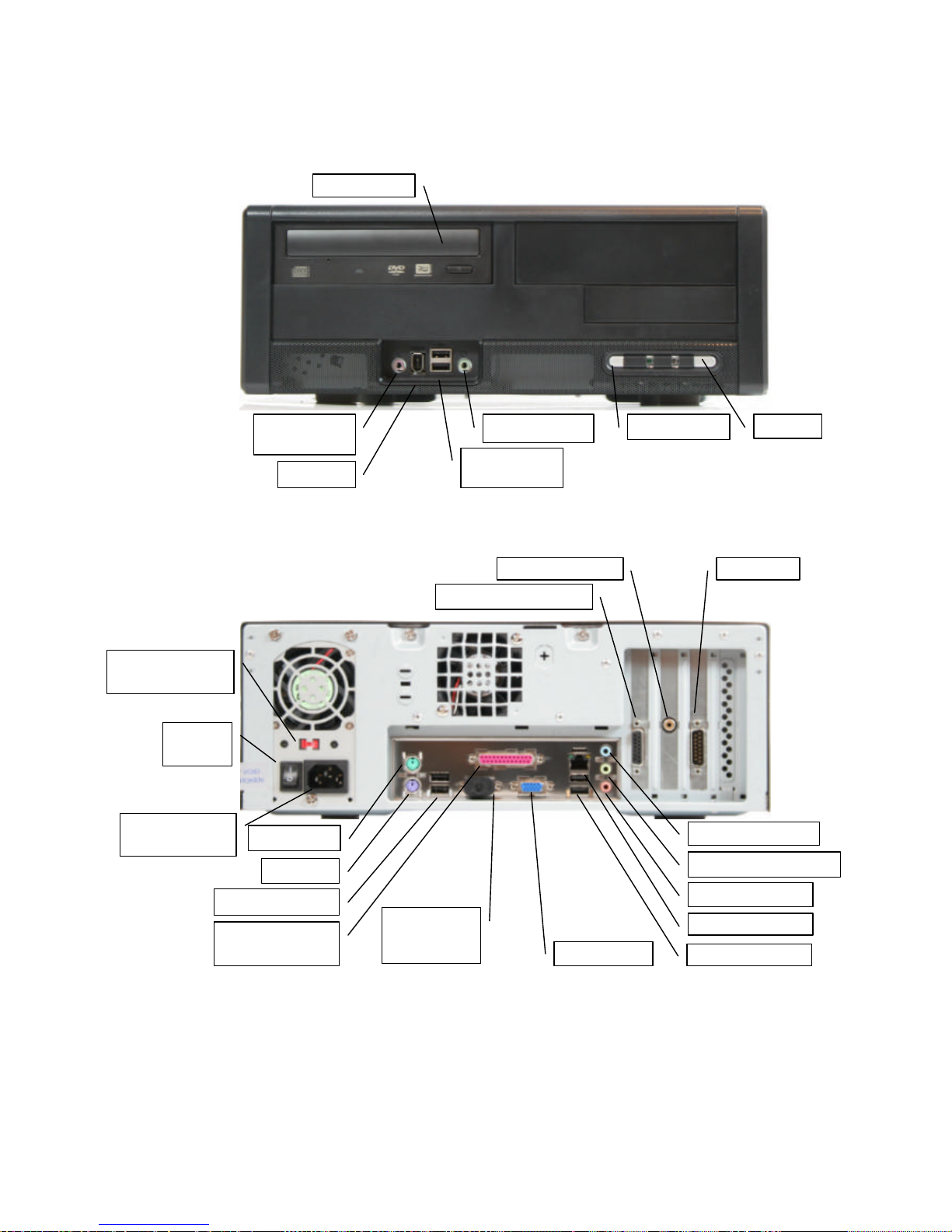
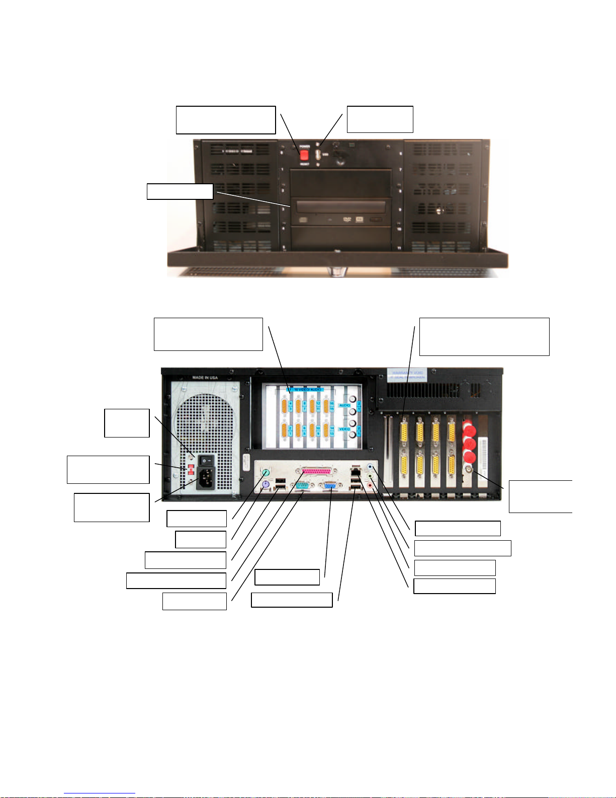
3.1 EDNS4000 Hardware layout
*using Intel D845EP Motherboard – may change without notice
Figure 3.2.2:
Rear Panel
Figure 3.1.1:
Front panel
Microphone
(pink)
1394 Port
Line-out (green)
2x USB 2.0
Ports
System Reset
Power
DVD Writer
110VAC/230VAC
selector switch
Power
OFF/ON
Power supply
(AC mains)
PS2 Mouse
Keyboard
2x USB 2.0 Ports
Parallel Printer
Port
Audio Line
-
In
(blue)
Audio Line
-
out
(green)
Microphone
(pink)
10/100 LAN
2x USB 2.0 Ports
PC Monitor
COM Port
*pre-defined, do
not use
Sensor/Controls Port
Spot Monitor
Video In
Page 20

DigiOp Installation Manual
Page 20 of 115
PTZ Controller Port / RS -232C When a RS-422/485 PTZ unit is connected directly to
the DigiOp DVR, it will connect using the EDNS- PTZ adapter (optional). This unit converts
RS232 to RS-422/485 (switchable). If a RS232 port is not available, use the
GSPORTMASTER USB to RS232 adaptor (optional).
Page 21
DigiOp Installation Manual
Page 21 of 115
3.2 EDNS6000 Series Hardware layout
Video input
Video loop out
(camera 9-16 top)
(camera 1-8 bottom)
Audio In
110VAC/230VAC
selector switch
Power
OFF/ON
Power supply
(AC mains)
PS2 Mouse
Keyboard
2x USB 2.0 Ports
Parallel Printer Port
Audio Line
-
In
(blue)
Audio Line
-
out
(green)
Microphone
(pink)
10/100 LAN
2x USB 2.0
Ports
PC Monitor
COM Port
*pre-defined, do
not use
Figure 3.2.2: Rear Panel
Figure 3.2.1: Front Panel
2x USB 2.0
Ports
System Power (up)
System Reset (down)
DVD Writer
Spot
monitors
Sensor
Inputs
Relay
outputs
Page 22
DigiOp Installation Manual
Page 22 of 115
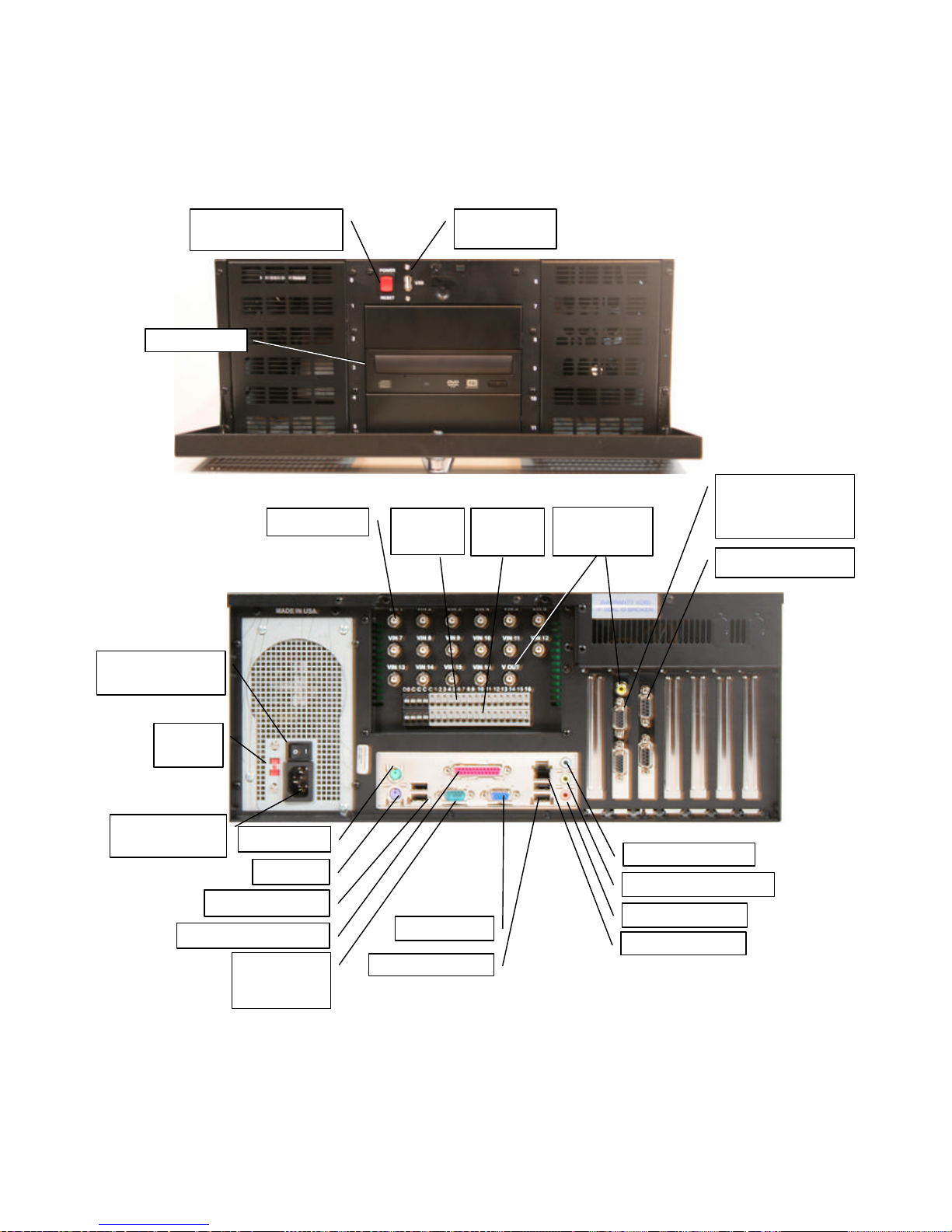
3.3 EDNS7000 Series Hardware layout
Figure 3.3.2: Rear Panel
Figure 3.3.1:
Front Panel
2x USB 2.0
Ports
System Power (up)
System Reset (down)
DVD Writer
Video in
3-4 7-8 11-12 15-16
1-2 5-6 9-10 13-14
Spot
Monitor
110VAC/230VAC
selector switch
Power
OFF/ON
Power supply
(AC mains)
PS2 Mouse
Keyboard
2x USB 2.0 Ports
Parallel Printer Port
Audio Line
-
In
(blue)
Audio Line
-
out
(green)
Microphone
(pink)
10/100 LAN
2x USB 2.0 Ports
PC Monitor
COM Port
Connection diagram
(label)
Page 23

DigiOp Installation Manual
Page 23 of 115
4 .0 Installation DigiOp DVR
This section describes how to connect DigiOp DVRs to peripheral devices.
Note: Before connecting the power, confirm the voltage selection the power
supply is switched to AC220V~240V->230V.
Be sure to turn off the power supply to the DVR before making any connections. (The
connections might vary according to the components of product model and the chosen
specifications of the user.
4.1 Connections
Connect the following;
Mouse
PC Monitor Output
Camera Input using D-Sub**
Power Cord
Optional connections;
Keyboard Alarm input/output Port
Spot Monitor Output / RCA Jack LAN Ethernet
USB Port devices Printer
Microphone Speaker Output / Line Out
Line Out
PTZ Controller Port / RS -232C
(** where applicable)
Page 24
DigiOp Installation Manual
Page 24 of 115
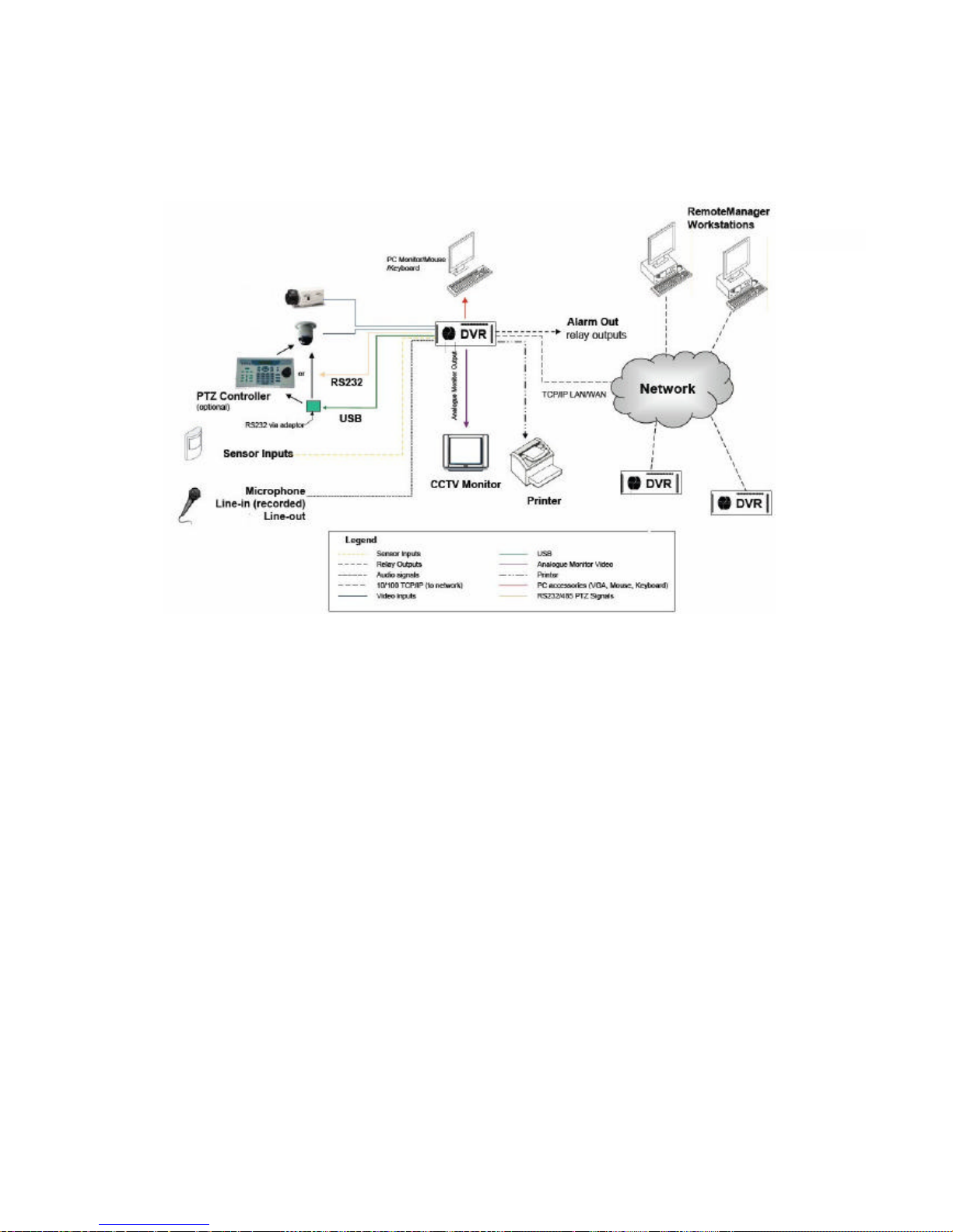
4.2 Typical System connection diagram
4.3 System Installation considerations and notes:
1) DigiOp DVR’s are compatible with PAL (or NTSC) analogue cameras .
2) To ensure high quality image capture, check the system for earth loops and
power fluctuations across the whole system.
3) Adjust the lighting, focus, or iris of the camera properly to avoid unnecessary
motion detection in low light conditions.
4) DigiOp DVR’s do not support PTZ data signals (or power) on the video coax.
Ensure separate cables are run to accommodate the system needs.
5) DigiOp DVR’s support both PC and spot monitors. Connect the analogue CCTV
monitor to the spot monitor output, and the camera images of the selected
channels will be displayed in sequence. The spot monitor output is always
displayed as full screen, and is independently controlled. For more detailed
information, refer to “Setting Customized Functions-> Select Recording.”
6) (EDNS4000) -> Only one Channel of audio is recorded and is synchronized in
the Channel 1 video. Connect the Microphone signal for voice recording into the
Microphone input jack. When the audio signal is line leve l, then connect to the
Line-in jack. C onnect the speaker to listen to a replay of the recorded audio. The
Cameras
Page 25

DigiOp Installation Manual
Page 25 of 115
output signal is line level so an amplifier is required to amplify the output signal for
a speaker. Refer to “Viewer->Other Settings” for volume control.
7) Sensor inputs are activated by dry clean contact devices and are not of a
‘balanced’ type. Inputs can be connected to either N/O (Normally Open) or N/C
(Normally Closed) type sensor contacts and the installer can configure (in the
software) each input depending on the type. To confirm correct operation, close a
sensor device for at least 0.5 seconds.
8) When using the Relay outputs, ensure the voltage/current capacity of the relays
are not exceeded.
9) The Network Connection is only used if the system is running RemoteManager,
or remote Web Browsing is required , or the system is integrated into an external
application e.g. Cardax. To achieve connection with the DVR, the DVR IP
address must be fixed and the dynamic IP address allocated by DHCP cannot be
used. Contact your network supervisor if you need any assistance.
10) If using a printer ensure you use a good quality color image printer and the
appropriate paper type to achieve best results. Refer to “Viewer->Other Setting”
for information on installing the corresponding printer driver.
Page 26
DigiOp Installation Manual
Page 26 of 115
5.0 Turning “ON” the DigiOp DVR
Before connecting the power, double check the power switch (AC110V ~ 120V ->115,
AC220V~240V->230V) is switched to 230VAC.
Make sure all connections of your system are firmly made (see Section 4.1 –
Connections).
Ensure all cameras are on and functional.
If all connections are correct and secured, turn mains power on to the DVR.
Windows XP will load, then the DigiOp DVR software. This will take a few moments.
The DigiOp multi image screen will appear and display the connected cameras.
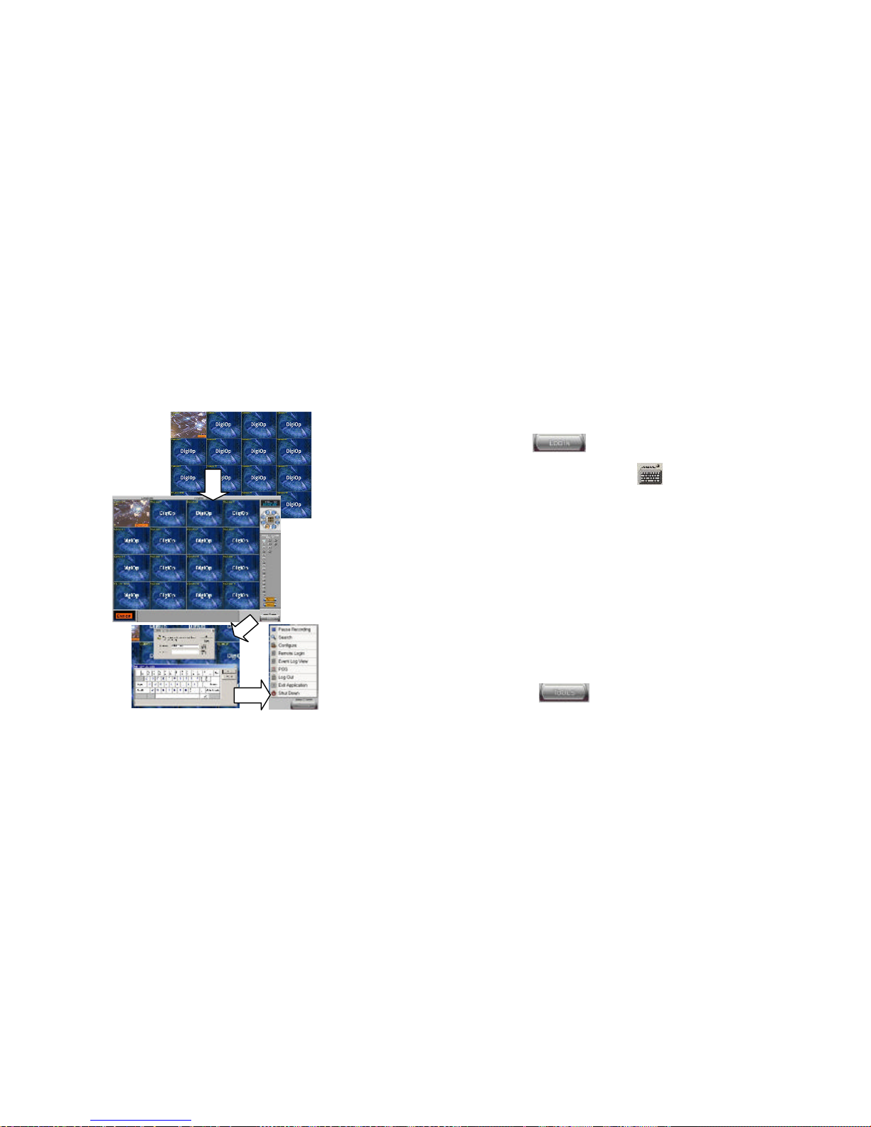
5.1 Logging In
a) Right click the mouse to view the DVR system controls.
b) Click the LOG IN button (bottom right corner).
c) Using either the on-screen keyboard or an external
keyboard, enter a username and password.
Note: The default Administrator username will be set to, “admin”.
Leave this and either click OK to leave the password blank or enter a
new password.
New Administrator passwords need to be confirmed by entering the
password twice. Passwords can be set and changed later.
d) Click the TOOLS button to access the DVR setup
using the Administrator options.
5.1.1 Users:
The DigiOp DVR’s have come with pre- programmed passwords or blank passwords.
When logging in for the first time and the system does not ask for a password or rejects
the entered password, try the following:
Defaults (Username: Password);
admin: dg2ad33
manager: dg2mgr13
installer: dg2in23
security: dg2seclv1
ac d
Page 27

DigiOp Installation Manual
Page 27 of 115
Only the Administrator (“admin” log on) is provided the ability to:
1. Exit Application
2. Shutdown
The “admin” user name can not be renamed. It is unique. The admin description and
password can be changed to suit.
To review and manage User go to the User Manage button on the Display tab.
TOOLS>CONFIGURE>Display Tab>User Management Button;
User Manager Window
Selectable user access options are;
• Camera
• Network
• Sensor/Control
• PTZ
• Color
• Real-time Display
• FPS/Resolution
• Schedule
• System
• Pause Recording
• Change Date/Time
• Search
• Events
• POS
The “admin” type user is provide full access and is unique (one per system and can’t
change user name).
The default “manager” user is provided all options (not the same access as “admin”).
Does not have privilege to:
• DVR Users accounts,
• restricted search functions (no access to Configure, SmartSearch, Sensor Events,
Still Image/Minute Backup (but Hour Backup is accessible)
• but can add Remote Users.
The default “installer” user is provide (by default) full access EXCEPT for the Search and
POS options
The default “security” user is provided (by default) only PTZ and Search (and POS if
installed)
Page 28

DigiOp Installation Manual
Page 28 of 115
Adding a Remote User Connection
To add a “Remote User” means that a Remote Connection is being added – not a
individual user as such. To add an authorized Remote Connection (a Remote User):
Network Tab
Remote User Settings section
Add Remote User
Enter the User’s Name and Password
5.1.2 RemoteManager Users
Adding a Remote User to a the RemoteManager;
TOOLS>OPTION>User Manager Tab
User privilege options are;
• Remote Playback (VOD)
• Pan/Tilt/Zoom PTZ
• Remote File Copy
• Local File Playback
• Site Detail
• Group Monitoring
• Two Way audio
• IntelliSearch
• Relays
• Remote Full Control
By Default the;
Administrator (admin) gets FULL access.
The Manager is provided ALL options except :
• DVR Users accounts,
• restricted search functions (no access to Configure, SmartSearch, Sensor Events,
Still Image/Minute Backup (but Hour Backup is OK)
• but can add Remote Users.
An Installer gets everything EXCEPT access to Search (and POS)
A Security User ONLY gets Access to PTZ and Search (and POS)
5.2 Shutting down the DigiOp DVR
a) This can only be done with the correct operator privilege level.
b) Click the LOG IN button
c) Enter the correct User and Password authorization
d) Click the TOOLS button
e) From the menu select SHUT DOWN – the system will shut down.
Note: The menu option Log Out simply logs out the current user. A new User will need to “log in” to access
the DVR functions and menus. “Exit Application” only stops the DVR functionality and takes the operator
back to the WINDOWS XP functionality. “ Shut Down” turns the entire machine off.
Page 29

DigiOp Installation Manual
Page 29 of 115
5.3 Abnormal shut down or restart procedures
The DigiOp contains a number of safety systems that ensure the system integrity under
abnormal operating conditions.
a) Operating System failure (lock up). The internal watch dog circuit monitors the
operation of the Operating System. If the system fails for any reason, the watch
dog will restart the machine.
b) The Operator presses the RESET button on the front panel. The system will
assume a fatal error and restore the Operating System from the internal secondary
backup and then restart the DVR.
c) The Operator presses the POWER button on the front panel. The DigiOp DVR will
close down and then close down Windows XP correctly.
d) The mains power source is disconnected (assuming no UPS). The system stops.
Once the mains power is restored the system will restore the Operating System
from the internal secondary backup and then restart the DVR.
Page 30
DigiOp Installation Manual
Page 30 of 115
6.0 System Operations
Once the DigiOp DVR has been connected to a reliable power source, all cameras and
peripheral devices are operational, and the DigiOp DVR software is functioning
(automatically loaded at start-up), an authorised User may change the screen view or
access the DVR functions through correct log in .
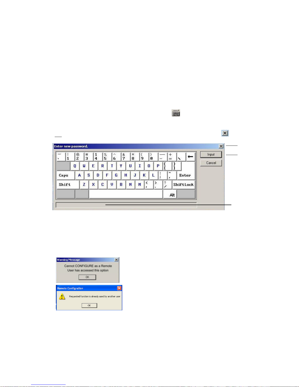
On-screen keyboard
System configuration can be achieved using a mouse. Where data entry is required,
DigiOp provides an on-screen keyboard as an alternative to an external keyboard. An
operator using the on-screen keyboard clicks the icon and the Keyboard appears for
data entry. As the Operator clicks on the alphanumeric symbols, the data appears in the
bottom text field as confirmation of entry. The Operator needs to press the INPUT key
(not the ENTER key) to confirm typed data before pressing the CLOSE button.
CONFIGURE MENU – available options
A number of functions under this menu will not be accessible or will not be applied to the
DVR configuration until recording is paused. If for any reason an option is unexpectedly
disabled (i.e. “greyed out”) try pausing the recording and check again.
Only one Administrator (local or Remote) can access the CONFIGURE menu at any one
time.
If a Remote PC administrator is setting the DVR from a
remote location, the local machine will provide a warning
message.
If the CONFIGURE menu is in use locally and a Remote
User tries to connect, a warning message will be
presented.
Close
Input
Data entered
Page 31

DigiOp Installation Manual
Page 31 of 115
Auto log off
IF the system is left in the full screen mode for
more than one minute, the DigiOp DVR will
automatically log out the user. A message will appear on
the screen for 5 seconds notifying the Operator that Auto
Log-off has occurred. Although this dialog box has an OK
button, confirmation is not necessary for this message to
disappear.
Using RemoteManager or other integrated remote applications
Ensure the version number of each piece of software is compatible. Incompatibility may
result in less than optimal performance.
Page 32

DigiOp Installation Manual
Page 32 of 115
Main screen
On-screen information:
1. DVR Location: Identifies a User-defined description of this DVR (to
configure, double-click the screen area and a text entry option will
appear or go to TOOLS>CONFIGURE>SYSTEM tab).
2. IP Address: If the system is connected to a LAN, a static IP Address
can be defined (to configure, go to TOOLS>CONFIGURE>NETWORK
tab).
3. Clock: Displays the DigiOp DVR current time and date. This can be
edited by double- clicking this area.
4. Round control dial cluster: Indicates the multi-screen mode (see
below)
Page 33

DigiOp Installation Manual
Page 33 of 115
5. Camera, Sensor and Control: Indicates the current status of the
camera record mode, the sensor input, and the control relay outputs
(see below).
6. DigiOp logo – system information: Double-click this logo image to
view the system details including; software/hardware versions, model
information, memory (HDD, RAM, Video), IP address, MAC address,
and recording average. See below for an example of available data.
Page 34

DigiOp Installation Manual
Page 34 of 115
7. On-image Information:
a) Camera Name (top left) – Operator definable on CAMERA tab
b) Audio recorded <A> (top left) -- indicates audio is recorded with this
video.
c) Record Mode M (bottom left) – each camera can record under a
different mode e.g. motion M, continuous record C, sensor record S,
no record F, etc. (Operator definable on the CAMERA or
SCHEDULE tabs).
d) PTZ available PTZ (bottom right) – right click the image to access
the PTZ control panel (Operator definable on PTZ tab).
On-screen control functions:
1. Round control dial cluster:
e) The numbered buttons (e.g. in this image 4, 6, 9, 10, 13, 16) represent
the options available for the number of images to be displayed on the
split screen. The centre grid image illustrates the display format for the
User and will change to reflect the option selected. The split screen (i.e.
multi-image screen) is also referred to as “display divisions”.
f) The number currently highlighted in yellow is the current selection for
the split screen (e. g. 16 images). By clicking this highlighted button the
Page 35

DigiOp Installation Manual
Page 35 of 115
next set of images are displayed (e.g. if the User is watching images 14, and clicks the “4” button the next sequence of 4 images will be
displayed . To configure the split screen sequences go to
TOOLS>CONFIGURE>DISPLAY tab >Time.
g) The “Sequence Images” button causes the images to
automatically “rotate” or sequence through the defined image
sequences. This can be stopped by clicking the same button again or
selecting a camera. The change period (dwell time) is defined between
1 to 60 seconds on the lower right of the
TOOLS>CONFIGURE>DISPLAY tab – “Display Division Rotation Dwell”
h) “Full screen mode” button hides the controls so the images take
up the entire screen. Click or right -click and the controls are redisplayed.
2. Camera, Sensor and Control:
i) Camera: When a camera is being recorded the associated “camera
connected” button will be highlighted. In “motion” record mode, this
button will appear normal (not recording).
j) Sensor: Each time a sensor is activated the associated button will be
highlighted (indicator only).
k) Control: These are interactive buttons connected to the available
relay outputs. If a sensor triggers an output relay the associated
button will be highlighted. A User can override the relay status by
clicking the appropriate button.
Page 36

DigiOp Installation Manual
Page 36 of 115
3. Setting the Clock
In most DVR applications the time of events is critical. DVR clocks can
be individually set or set by a “time server”. DigiOpTS is a time server
application that will synchronize all DigiOp DVR clocks on a network to a
single time. If the DVR is not on a network, simply double-click the clock
on the top right of the screen.
Choose your region (“Select Nation”) and set the time.
Automatic daylight savings can be applied if the
“Automatically adjust for daylight savings changes” check box
is checked.
If there are specific daylight savings
requirement, from the “Select Nation” dropdown list, select “USER EDIT”. This will
enable the Operator to configure the daylight
savings parameters at the bottom of the
window.
Switching between multi-image screen and single-image screen.
From a multi-image screen double-click the image you wish to view in full screen mode.
The image will expand to fill the entire image area. Double-click to restore back to the
multi-image mode.
Page 37

DigiOp Installation Manual
Page 37 of 115
TOOLS button
By clicking this button an authorized operator can access the DVR configuration and
Search functions. The menu comprises of 9 options:
1. PAUSE RECORDING: Pauses the recording of all cameras to the
hard drive. In most cases it is required to pause the recording to
change recording type parameters e.g. fps, resolution, schedule, etc.
2. SEARCH: Opens a Search application. Also includes video backup
(video clips, entire records) and still image save/print..
3. CONFIGURE: Opens the main DVR configuration and settings menu.
4. REMOTE LOGIN: Opens a real time log of logins to the DVR from
Remote devices (can include RemoteManager and integrated
software e.g Cardax Access Control).
5. EVENT LOG VIEW: O pens a real time log of the operational and
alarm events generated by the DVR.
6. POS (Point of Sale) – also referred to as DTM (Data Transaction
Manager). A separate licensable software package used to record
transactions (e.g. cash register) with video clips. Not activated,
requires licensing.
7. LOG OUT : Current user can log out. Log-out is not automatic.
8. EXIT APPLICATION: Shut down the DigiOp DVR and exit to
Windows XP environment.
9. SHUT DOWN : Turns off the entire machine.
DVR Configuration Menu Options:
The CONFIGURE menu is accessible by an authorized User by clicking the TOOLS
button on the main DVR screen. This menu covers the DVR preferred settings relating to;
Page 38

DigiOp Installation Manual
Page 38 of 115
CAMERA Tab:
Video input status and selection
The camera icons at the top of this tab identify the channel input status.
• Camera source connected to channel 2 video input and selected for
configuration. While this icon is highlighted the options displayed are
related to this camera.
• Camera source connected to channel 1 but not currently being
configured. To switch to this camera, click on this icon.
• No video source connected to channel 5.
Camera identification
The descriptive name entered here will appear on the main
screen and the RemoteManager software as an identifier for
this camera. Be as descriptive as possible to avoid
confusion. The name can be entered directly into the text
box using an external keyboard or by clicking the on-screen
keyboard icon and using the mouse.
Page 39

DigiOp Installation Manual
Page 39 of 115
Recorded View
The selected camera will appear in the “Current Recorded
View”, assuming the DVR is still recording that view. If the
DVR recording has been paused, a default image will be
displayed.
If the DVR is set up for motion detection, any detected
movement will be highlighted on the image as white squares
( this feature varies between DVR models and software versions).
The current kbps and estimated HDD storage is also
repeatedly updated. These are only estimates , based on
current rates and settings (this feature varies between DVR models
and software versions).
Recorded video quality
This slider control enables the operator to adjust the level of
compression based on the selected compression type (e.g.
MPEG, MPEG4, H.264). Moving the s lider to the far left will
produce small files of low resolution to maximize hard drive
storage capacity. Moving the slider to the far right will
maximize the quality for scrutiny later but will consume more
hard drive space. The file size impact is indicated by the
“current kbps” update (see above) and can also be
monitored on the RemoteManager software.
Security Screen Mode
Records images from a camera without displaying the
images to the current Operator.
In this mode the Operator will only see the default image on
the screen with the message “Security Screen” in the top left
of the image. Each camera can be individually configured
for this mode. In this mode the images are not streamed to
Remote Viewing applications.
Page 40

DigiOp Installation Manual
Page 40 of 115
Watch Mode
A camera configured for “Watch Mode” will NOT be
recorded and can only be used for live surveillance.
When selecting this option the image on the CAMERA tab
with change to the default image as it is no longer being
recorded.
In this mode images are not streamed to Remote Viewing
applications. If the mode is changed to “Watch Mode” during
remote viewing a message will be displayed on the remote
viewing application and the image will freeze.
Simple Recording Time Schedule
This schedule is not intended to be a comprehensive
recording schedule solution. Each camera can have a
different simple recording schedule defined.
By default the DigiOp DVR is set to 24-hour, 7-day
recording. The Operator can modify this by selecting a start
recording time (From Hour) and then selecting an end
recording time (to Hour) from the drop-down hour lists
beside the “Time Range 1” option. The DVR will start and
stop recording on each WEEKDAY at these times.
The Operator can also select if these times apply to
Saturday and/or Sunday by checking the appropriate
boxes.
A second recording time option can be selected by checking
the “Time Range 2” box.
Note: This option will only be available if the recording is
PAUSED and the schedule on the SCHEDULE tab is
disabled.
Note: For more comprehensive options go to
TOOLS>CONFIGURE>SCHEDULE tab.
Motion Detection Area
The incoming video can be used to trigger recording. This
option only functions if the Continuous/Motion record mode
is set to Motion. Do this by clicking the CONTINUOUS icon
Page 41

DigiOp Installation Manual
Page 41 of 115
on the lower right of the CAMERA tab screen (unless
already set to MOTION).
There are two available modes of motion detection:
1. Monitor the entire image for motion
2. Operator-defined “motion sensitive” areas on an
image. Only when these defined areas detect mo tion
will the DVR start recording this camera e.g these
areas can be positioned over doors, windows,
parking areas, etc.
Operator- defined “motion-sensitive” areas can be added to
the right-hand image on the CAMERA tab using the left
mouse button and removed by using the right mouse
button.
Double-clicking the image will fill the entire image with
motion-sensitive areas so the Operator can remove rather
then add sensitive areas.
If errors are made, the Operator can clear the entire screen
and start over by checking then unchecking the “Cover
Entire Area” check box. A total of 300 motion-sensitive
areas can added.
Motion Detection Sensitivity
This slider with define the amount of movement (motion)
required within motion-sensitive areas before the DVR
recognizes it as an activation trigger.
If the camera is monitoring a distant image and the
expected movement is very slight, the sensitivity needs to
be very high. If the image is a doorway and only people are
to be detected rather then small pets, the sensitivity can be
very low.
Page 42

DigiOp Installation Manual
Page 42 of 115
Motion Sensitivity “quick start” guidelines
.
1. Entire Movement : When the entire body moves.
2. Partial Movement: When only the arms or legs move.
3. Movement Speed : Approx. ±20 compensation of recommended sensitivity value
(High speed : max. +20, Low speed: max. -20).
4. Number of Persons: If the number of persons on the screen increases, the motion
can be detected at a lower sensitivity level. Adjust the sensitivity value accordingly.
Note: If the DVR is to record in low light conditions with poor illumination, cameras may
try to compensate resulting in image noise which will trigger the DVR to record and waste
hard drive storage unless Sensitivity is set to a lower position on the slider.
Page 43

DigiOp Installation Manual
Page 43 of 115
Network Tab
If the DVR is to be used on a Local Area Network (LAN) to interface with another
application, or so it can be accessible via a web browser or RemoteManger software,
then the IP address of the DVR must be fixed.
Enabling network connectivity
Enable network use by checking the “Enable
Network” check box
Network Settings (EDIT)
Click the EDIT button to open the “Network configuration settings” window.
The three critical items are the Adaptor (leave as default), the DVR IP Address and
Subnet Mask.
Page 44

DigiOp Installation Manual
Page 44 of 115
Network Adaptor List
The default adaptor value is normally okay but an
alternative maybe selected using the drop -down list.
IP Address
To enable other applications to reliably access this
DVR, a fixed IP address is required. Enter the DVR IP
Address and Subnet Mask into the appropriate boxes in
the correct format (xxx.xxx.xxx.xxx).
Tip: To identify the Subnet Mask, check the
network details of your Remote PC configuration.
You can go to START>RUN, type in CMD <then
press enter>, then at the prompt type in IPCONFIG
<then press Enter>. The PC IP Address will
appear with the Subnet Mask. Copy the number of
the Subnet Mask to the DVR Subnet Mask.
Gateway
If the LAN has access to external networks a gateway
can be entered but is not necessary.
DNS
Enter DNS details as necessary or leave as default.
Page 45

DigiOp Installation Manual
Page 45 of 115
Additional Network Options
Bandwidth Throttle or Bandwidth Limit
The maximum bandwidth consumed by this
DigiOp DVR for remote connection (any LAN
traffic) can be defined here in Mbps and Kbps
(bits per second NOT Bytes per second).
By default it is set to the maximum of 100Mbps but depending on the video information,
video can be still streamed in Kbps range. Note that 0 is unlimited.
Restriction of the bandwidth will reduce the fps being streamed across each connection
proportionally. To check the current consumption of bandwidth monitor the “Current Used”
meter which is updated regularly and averaged.
Time Synchronization
Time syncing is critical if using time related external
software applications (e.g. access control). Use a
network wide server application ( e.g. NET TIME) to
synchronize all network-based PCs and use the DigiOp
Time Server application (DigiOpTS.exe) to synchronise
the DVRs to these PCs.
The DVR Server will only update its time on the hour as
it closes off one DSF and starts another.
Install the DigiOpTS.exe on to a remote PC or server under C:\DigiOp\ RemoteManager
(see below) and run the application.
Page 46

DigiOp Installation Manual
Page 46 of 115
Ensure DigiOpTS.exe runs whenever the PC is started.
This PC will broadcast at regular intervals to all DVRs on the network that have the
“Synchronize with DigiOpTS System Time” option checked.
Interval between broadcast is defined in the DigiOpTS.ini file – open and modify in MS
Notepad.
Set this to 30 to 60 seconds to avoid nuisance traffic on the LAN.
The time of DVR updates is recorded on the “Synchronised Time” monitor with any
variances noted.
Page 47

DigiOp Installation Manual
Page 47 of 115
Remote Connection Settings
Remote Users
Any remote PC or application (using the API)
attempting to connect to the DVR must be
authorized. To authorize a remote connection
click ADD to enable a Remote User
connection.
Note: Multiple connections to the DVR can be
achieved using a single remote connection
authorisation, but this is not recommended.
The manufacturers of DigiOp recommend no
more then 32 streaming connections should
be made although up to 100 are possible. A
streaming connection is a video channel (not
to be confused with 32 Remote Users).
Multiple Remote Users can be registered and
connect when required. Time limits on
connect duration or monitoring for idle
conditions can be set (see above). A Remote
User connection only requires a User ID and
password.
To DELETE or MODIFY Users on the list,
simply click to highlight then chose the
function required.
Remote User privileges can not be altered
remotely (must be done at the DVR).
Limits:
User Name 20 Characters
Password 15 Characters
Channels that can be streamed: 100
Page 48

DigiOp Installation Manual
Page 48 of 115
Remote Event Notification
For RemoteManager Users to receive events
(alarms) from the DVR, their PC IP Address
must be registered under the “Remote IP
and Phone Number” list. There is a limit of 10
that can receive notification. *DigiOp DVRs
do not come standard with diallers/modems.
The ADD button brings up the ADD window
which prompts you for the RemoteManager
PC IP Ad dress to be added.
To DELETE a PC, highlight the item on the
list and press DELETE.
Remote Connection Time Limit – refer Event Notification list
Auto Disconnect on no activity after:
The RemoteManager PCs that have their IP address
entered in the "Remote IP and Phone numbers” list will
be automatically connected by the DVR when a sensor
event occurs (up to 32 connections). "Connection time
limit when sensor occurs" determines how long this
connection should exist. Time range is up to 20 minutes.
Connection Time Limit
See above. When a DVR has made a connection to a
remote PC (after a sensor trigger event), this setting
disconnects the remote PC again after the specified
time interval. For unlimited connection time uncheck this
option (default). Time limit range is up to 120 minutes.
Page 49

DigiOp Installation Manual
Page 49 of 115
Transmission Time Limit – on Sensor activation.
Video will stream to RemoteManager on
sensor activation. The time that video
streams for may be different to the Sensor
Record period (see Sensor and Controls tab).
To limit the transmission time select the
desired period from the drop down list.
The options range from 10secs to 10mins in
various increments. “No Limit” is also an
option.
Page 50

DigiOp Installation Manual
Page 50 of 115
Sensor and Control tab
Most of the functions on this tab are selected by clicking the icon image. A second click
will deselect that function. A greyed out icon implies the item is not available to configure,
or has not yet been configured on a different tab.
The term “sensor” is interchangeable with “input” and the term “Control” is
interchangeable with “output” or “relay output”.
Generally an input is connected to a dry clean set of normally open (N/O) or normally
closed (N/C) contacts. No ‘end of line resistors’ or “balanced input resistors’ should be
used. The exception is the H480R-16 (D1) unit (EXTIO-16) that uses an external I/O
device that requires a 2.2K? resistor (refer to EXTIO-16 Manual).
Enabling the Sensors and Controls
This Sensor and Controls tab defines the function of the
INPUTS and OUTPUTS of the DVR. Unless the “Enable
Sensors and Controls” check box is checked, the I/O will not
function as expected.
Page 51

DigiOp Installation Manual
Page 51 of 115
Sensors can be disabled by schedule as defined on the top
right of the Sensor and Controls tab. By default sensors and
controls are scheduled for 24 hour operation (assuming they
have been ‘enabled” – see above)
To change the default, simply drop the “From Hour” list and
select the “enable sensor time” and then drop the “To Hour”
list and select the “disable sensor” time. This schedule is
applicable for a full 7 day period.
Note: For comprehensive scheduling of sensor monitoring
go to TOOLS>CONFIGURE>SCHEDULE tab.
Associating Sensors (inputs) to create an action
The available sensors (inputs) are highlighted in blue across the top of
the tab window.
If the selected sensor is available, its icon will turn yellow.
Not all DigiOp DVRs come with a complete compliment of inputs and
outputs. Sensors that are not available will be greyed out.
Note: For this discussion we are going to use the EDNS4000 unit that
has 8 cameras, but only 4 sensor inp uts and 2 control outputs.
Causing a Camera(s) to record on a Sensor trigger
To associate a sensor (input) with a single camera, select the available sensor, then click
the available camera. This will cause the camera to start recording when the sensor is
triggered.
A single sensor can be associated to many cameras, so a single sensor input can cause
multiple cameras to record. A camera may also be associated with more than one sensor
in which case it will start recording when any of its associated sensors are triggered.
Scenario A: Sensor 1 is associated with Camera 1 and
Camera 2, and Sensor 2 is also associated with the Camera
1 and Camera 2. Triggering Sensor 1 or Sensor 2 will result
in both cameras recording.
Scenario B: Sensor 1 is associated with Camera 1 and
Camera 2; Sensor 2 is associated with Camera 1 and
Camera 3. Triggering Sensor 1 will cause Cameras 1 and 2
to record. Triggering Sensor 2 will cause Cameras 1 and 3 to
record.
Page 52

DigiOp Installation Manual
Page 52 of 115
Causing a Sensor trigger to move a camera to a pre-defined PTZ position.
Sensor inputs can be associated with any available camera PTZ preset location. Using
our Talon PTZ, up to 127 presets can be selected. Any one of the 127 preset locations
can be associated with a sensor input.
Note: The Camera PTZ must be enabled (go to the TOOLS>CONFIGURE>PTZ tab) and
the PTZ Presets must be defined.
Scenario C: Sensor 1 is to swing Camera 1 (PTZ) to the Preset 5 position.
To do this; select Sensor 1, select Camera 1, drop down the PTZ list under
Camera 1 and click on “5”.
This could be just as easily done for multiple cameras.
Scenario D: Sensor 1 is to swing Camera 1 (PTZ) to
the Preset 5 position and Camera 3 (PTZ) to Preset
127 position.
To do this; select Sensor 1 icon, select Camera 1 icon,
and select “5” from the PTZ drop-down list under
Camera 1. Then select Camera 3, and select “127”
from the PTZ drop -down list under Camera 3.
Now triggering a single sensor input will cause both
Camera 1 and Camera 3 to reposition and record.
Causing a Sensor trigger to activate a Camera and a Control (output relay).
Sensor inputs can be associated with any available Control output (relay) BUT must also
be associated to a Camera. Different DVRs have different combinations of sensors vs
outputs. The icons on the Sensor and Control tab will identify the available I/O.
The Controls (outputs) are identified by the “Warning Light” icon.
Available Controls are displayed as dark grey. A smaller grey
Control icon indicates the Control is being used by another
DVR function.
A red Control icon indicates the Control is currently selected.
To associate a Sensor to a camera and an output relay, simply select the
sensor icon, select the camera (and PTZ preset position if required) and
then select the Control. As each device is selected, its associated icon will
be highlighted.
Scenario E: Triggering Sensor 1 will record Cameras 1 and 2, cause
Camera 1 to go to Preset Position 2 and cause Relay Output 2 to activate
e.g. turn on lighting.
Page 53

DigiOp Installation Manual
Page 53 of 115
Sensor Type
Specify whether the sensor is of the “normally open” type (i.e.
the sensor with close the circuit on activation), or of the
“normally closed” type (i.e. the sensor will open the circuit on
activation).
Sensor Alarm
This provides an audible alert for sensor activations. When
this is selected the DVR will beep on sensor activation. Each
sensor can be individually set.
Sensor Recording Time
Once the sensor has triggered, a camera will start to record.
This slider control sets the period of time for which a camera
will keep recording after detected motion ends. You can
extend the record period from 3 seconds to 5 minutes.
Increments:
3- 15 seconds by second
15 to 60 seconds 5 second increments
1 to 5 minute 1 minute steps
Sensor 4 input used for shut down
External power failure, surge and spike protection is highly
recommended. If the UPS provides a relay output on power
protection, this can be wired to the DVR to notify it to start the
auto shut down procedure. This will eliminate a system power
off and reduce the possibility of system damage that often
occurs with power disruptions.
The system will close down after the period selected and will
take approximately one minute to do so. So if your UPS is a 5
minute unit for example, select a period of 3 or 4 minutes.
The DVR will not restart on power up if this method of power
down is chosen.
Page 54
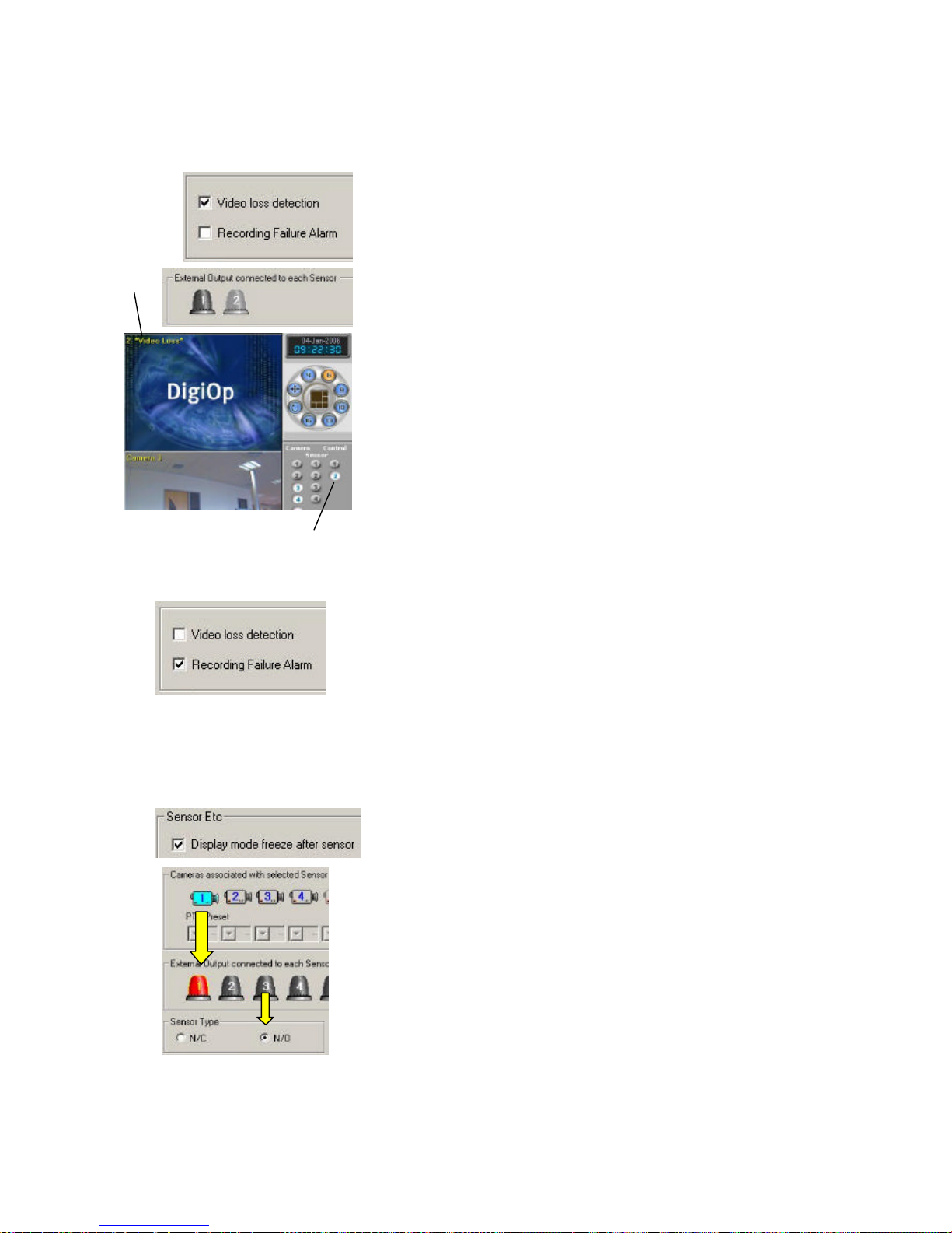
DigiOp Installation Manual
Page 54 of 115
Video Loss Detection
Turning this setting ON will take control of your last output
control relay, activating it for one to two seconds whenever
the system detects video loss on any connected camera. On
a system using two output control relays (EDNS4000), output
#2 will be activated when video loss is detected. On a system
using 16 output control relays, control relay #16 will be
activated.
This is a “global” setting across all connected cameras.
On activation the control relay will activate for 1 to 2 seconds,
then reset.
The control relay will reactivate each time the system detects
a video loss. So, a camera that is intermittent will continue to
reactivate the alarm until the system is repaired.
In the EDNS4000 example, a “VIDEO LOSS” message will
appear on the screen and control #2 will highlight in the
division of the camera that has terminated.
Recording failure Alarm
If, for any reason, a video channel fails to record to the hard
drive (e.g. HDD damage) the second to last control relay will
activate e.g. EDNS4000, output #1 will be attributed to
notifying of recording failure. On a system using 16 output
control relays, control relay #15 will be assigned.
An external device can be connected to notify an alarm panel
or siren of the compromised system.
Note: System events will be logged to the Event Log.
Display mode freeze after sensor
When this mode is selected and the sensor (corresponding to
a selected camera) activates, the system automatically
maxim izes the image display of that camera for the duration
of the preset “Display Mode Freeze after sensor,” regardless
of the display mode selected.
After the image is reviewed the User can elect either to
maintain this display mode (one image) or manually return to
the 16-division display mode by double clicking on the image
(or clicking an alternative division mode). If the system was
in “rotation mode”, the unit will go back to the 16-division
screen mode.
Page 55

DigiOp Installation Manual
Page 55 of 115
Motion Sensor
This enables a motion detection activation to be displayed to
the User rather then just recording the event.
This option can be individually set for each sensor (not
global). Checking this option associates the sensor to its
appropriate camera and clears any other pre-selected
associations to that sensor. The sensor can also be
attributed to the associates control relay (one only)
which will trigger on a physical sensor input activation or
a motion sensor activation.
Note: If using a schedule, ensure the camera is set to
“Motion and Sensor” (M,S) mode. If set to “Motion only”
(M), the motion sensor option will not activate.
When a motion detected event occurs, the camera,
sensor, and control icons for that camera are highlighted
(if selected) on the main screen. In this example (see
image), Sensor 1 and Sensor 2 have the “motion
sensor” option selected but Sensors 3 and 4 do not.
Users can be alerted by using the “Enable Audio”
option. A sensor can also trigger recording (see
Schedule for M,S mode, but the “Sensor Type” must be
pre-selected. Both these options must be selected prior
to checking the “motion sensor” option.
Pre-alarm record period
This is the period (1-6 seconds) that is attached to the
video file at the time of a sensor activation. Video is
cached on the DigiOp DVR a t the “normal” recording fps
rate. On an alarm activation, this video and subsequent
video is stored as a single video record.
The record length then becomes:
Pre-Alarm <Alarm trigger > Sensor Recording Time
Page 56

DigiOp Installation Manual
Page 56 of 115
Recording Mode – Normal or Optimized
This mode selection is only applicable to sensor
activiations NOT related to purely motion detection
activations.
This means, if the camera channel is selected to record
on sensor (S) or motion/sensor (M,S) modes , the record
will be “Optimized” at the time of the sensor trigger.
When “normal” is checked, the resultant recording from sensor activation will be at the fps
set by the Operator. If “Optimize Frames Per Second” is checked the resultant recording
will be at the maximum available fps.
Example: If a cam era is recorded at 5fps and the “Optimize Frames Per Second” option is
checked, then when the sensor is triggered the camera will be recorded at 25fps (if
available) till the end of the “Sensor Recording Time” where the fps will return to 5fps.
Page 57

DigiOp Installation Manual
Page 57 of 115
PTZ Tab
To activate the use of a PTZ on one of the cameras, check the “Use PTZ” check box
Page 58

DigiOp Installation Manual
Page 58 of 115
Typical PTZ wiring
Enable PTZ
The available cameras are highlighted across the top
of the window. Camera icons in grey are not available
for configuration. If the Operator is to use a PTZ on
one of these cameras, select the appropriate camera
icon and check the “Enable PTZ” check box.
A PTZ camera does not require configuration unless
it is to be used from the DigiOp DVR.
Page 59

DigiOp Installation Manual
Page 59 of 115
PTZ Protocol
Once the PTZ is enabled for the selected camera, use the PTZ Protocol drop down box to
select the pre-defined protocol to be used. If your specific PTZ is not listed, look for a
similar model, or the same manufacturer, and try it. If a special protocol is to be written,
please contact your DigiOp DVR provider.
Communication with the PTZ is through a COM port. COM ports can be created by using
USB to Serial converters (e.g. GSPORTMASTER). These are readily available and can
be configured under Windows. The Default is COM 1 – do not use COM 4 as it is predefined for use for I/O communications. If adding a COM port and once the COM port is
established, use the drop down PORT list to select it. Multiple protocols can use the same
PORT.
Adding a Protocol
If the PTZ protocol is not on the drop down list and
your DigiOp provider has emailed you a file
containing a new protocol then follow these steps to
install it:
1. Save the file to compatible media (e.g. CD, USB
memory device, floppy disk, etc).
2. Click the “Add PTZ protocol” and the “Find
Folder” window appears. All previous settings
will be cleared in preparation for a new protocol
for this camera.
3. Find the new file on the memory media, and
double click. Click OK to load.
4. The new protocol wi ll appear on the list.
5. Select the new protocol and continue with the
install.
Page 60

DigiOp Installation Manual
Page 60 of 115
PTZ Camera Address
Each PTZ on the PTZ network will have its
unique ID address number. Enter this number
using the on-screen keyboard and press input
then close the keyboard.
If the address is correct and the DVR is able to
communicate with the PTZ the control panels
will identify the available functions the DVR
can access on the PTZ. If the PTZ address
number has already been used for another
camera then a warning message will appear
prompting for correct data.
Page 61

DigiOp Installation Manual
Page 61 of 115
Set up procedure
To set up and test the camera PTZ control functions (assumes COM port assigned and
converter working );
1. Go to TOOLS>CONFIGURE>PTZ Tab. Check “USE PTZ ” box.
2. Select the Camera icon . The camera image will appear in the “Current View”
window.
3. Check “ENABLE PTZ ” box (control panel will highlight).
4. Select the PTZ protocol (or add a new one)
5. Select the COM port the converter is connected to
6. Input a unique Camera Address using the on- screen keyboard icon.
7. Use the control panel (e.g. Pan/Tilt tab) to test the PTZ movements.
2 1 3 4 6 5 7
Page 62

DigiOp Installation Manual
Page 62 of 115
Preset
The Preset options vary according to the selected PTZ
Protocol. As an example we have used the GS Talon
protocol. This camera system has presetable
locations.
SET
Move the camera and view to obtain the desired image
for the preset. Click on a preset number on the list, and
then press SET.
LOCATION
To name a preset , select it and click LOCATION. An
on-screen keyboard will appear. Type in a name and
click INPUT.
MOVE
To test a preset, select it and click MOVE. If correctly
set, the camera will move to the correct location.
The other functions on the GS Talon protocol
relate directly to the features and functions of
that particular PTZ camera system. Refer to the
manufacturers’ handbook for more detailed
instruction.
Page 63

DigiOp Installation Manual
Page 63 of 115
Color Tab
By selecting the camera at the top of this tab, the image content (luminance/chroma) can
be adjusted. Each camera image on the system can be customized to enhance th e
image. For example, if the image colors are too contrasting, the image could be
customized to reduce the contrast.
The controls are
self explanatory.
All kinds of
effects can be
achieved e.g.
messing with
Camera 1;
If it all gets out
of hand, click
the DEFAULT
button to reset
the settings to
‘normal’.
Page 64

DigiOp Installation Manual
Page 64 of 115
Page 65

DigiOp Installation Manual
Page 65 of 115
DISPLAY Tab
This is provides the operator some fundamental control over the display and recording
options of the DVR. A number of items can be selected here, but maybe overridden with
more defined options of other tabs e.g. Frames per second, compression.
Enable/Disable Camera Recording
By default all operating cameras connected to the DigiOp
DVR produce highlighted camera icons. The greyed out icons
represent channels that do not recognize any usable video
input (see image – camera 5- 16)
To disable a camera from recording to the hard drive, click
the icon. It will retain its blue numbering and dark outline but
lose its highlight (see image camera 2). On a “real -time” unit,
the image will still appear on the main screen, but on the nonreal-time display units the camera image will not be present.
Page 66

DigiOp Installation Manual
Page 66 of 115
Password Protected Recording
Applying a Password to video and/or audio provides an extra
level of security for the encrypted data on the hard drive.
A password can be assigned to the video, the audio, or both.
The password can contain up to 50 characters, including
lowercase alphabet letters and Arabic numbers.
Note: A password is only applied to files at the BEGINNING of the next recorded hour
unless recording is stopped and restarted. For example: a new password is selected at
3:20, the password will be used to encode recordings after 4:00. So the images recorded
between 3:20 and 4:00 will not be protected with the new password unless recording is
stopped and restarted.
The password will be required each time recording video is to be watched from the DVR
or any external application. There is no way to recover this password if lost.
To use the password option, click the
“Password Protected Recording” checkbox.
Chose either to have a common password
on video and audio or separate passwords
using the “Same as video” check box.
To enter a password into the appropriate
option, click the associated ENTER button.
An on-screen keyboard will appear. Type in
the password and click INPUT. A second
on-screen keyboard will appear for you to
verify the password. Re-type it and click
INPUT. If the passwords match – all will be
well.
User Management
All Users are managed from this option.
You can only manage Users if you are logged on as the Administrator. No other level of
Operator (User) has this privilege. User Management is not accessible from remote
application software. A User account applies to both the DVR and the DigiOp Viewer
software.
User privileges are defined by the CONFIGURE tabs and the functions a User can access
e.g. not all users can change time and date, only administrators can manage users, and a
user maybe only be able to view the main screen, etc.
Configuration options;
Camera tab Network tab Sensor/Control tab
PTZ tab Color tab Display tab
FPS/Resolution tab Schedule tab System tab
Page 67

DigiOp Installation Manual
Page 67 of 115
Functions options;
Pause recording Change date/time Search
Events log Point- Of-Sale (DTM) Real-time Display
Limits:
User name: 64 Characters
Description: 256 Characters
Password: 64 Characters
Add, Delete, Modify User Profiles
• To configure users, click the MANAGE
button. The buttons are self explanatory.
• To delete a User, highlight the User then click
DELETE (there is no “undo”).
When adding or modifying the properties of a User profile the User Property window will
appear. Each line can be entered or modified.
When defining a new user the “Supported Functions ” list (i.e. the User’s privileges) is
blank. A User with no privileges can only manipulate the main screen view modes and
check system information by clicking the DigiOp logo’s, but they cannot change any
configuration options.
• To add a function or privilege to a User, highlight the function from the list on t he
right and click the button so the selected option is removed from the
“Unsupported Function” list to the “Support ed Function” list.
• To remove a privilege, reverse the process, selecting an item in the “Supported
Function” list and using the REMOVE button.
Note: POS (Point-Of-Sale), also referred to as DTM (Data Transaction Manager) is a
licensable software package and is not part of the “normal” DVR licensed configuration.
Leave this on the “Unsupported Function” list.
Page 68

DigiOp Installation Manual
Page 68 of 115
Export and Import User Profiles
A User profile contains the information relating to a User (e.g. their username, password,
and what privileges they have). User profile lists (for an entire list of Users) can be
exported and imported to/from extern al storage devices (e.g. USB memory devices), and
can be copied between DVRs to save duplicated inputting of User data. To export User
profiles, click on EXPORT . When prompted, enter the location where the file should be
saved to, and then click OK.
The Users in an exported User profile list can be merged to another machine.
1. Any User profiles not on the machine will be added from the file
2. Any User profiles already on the other machine that exist on the file, will be
updated with the file information including passwords, privileges and descriptions
(this is not selectable).
3. The “administrator” User profile information will be updated too – ensure the
administrator password is recorded before importing and overwriting the current
administrator profile.
External Monitor
The External Monitor (spot monitor – if available) is the ANALOGUE monitor plugged
directly into the DVR.
Each of the DigiOp DVR models handle the external monitor option slightly differently.
EDNS4000 Display tab
The external monitor sequences
through an Operator -defined
sequence of video channels. To
create a sequence to be
displayed on the external
monitor, check the “Sequence”
check box and check the
cameras to view. Set the dwell
time. The Sequence option can
be left checked or uncheck to
avoid accidental reconfiguration.
EDNS6000 Display tab
The EDNS6000 unit uses two
external monitors. Both external
monitors mimic the PC monitor.
Configure the PC monitor
display to suit requirements.
Page 69

DigiOp Installation Manual
Page 69 of 115
EDNS7000 Display tab
If the “Sequence” option is
checked the External Monitor
will display images using the
Operator-defined sequence and
external monitor dwell time. If
the “Sequence” option is not
checked the external monitor
will mimic the PC monitor.
The External Monitor can be configured to
display the same sequence as the DVR
VGA monitor , or configured to display a
sequence of images.
To define an External Monitor sequence and images for viewing;
• Check the “Sequence” check box
• Select the dwell time for displaying images (global setting)
• Select the cameras to view
Dwell time is configurable between 1 to 60 seconds.
Note: The EDNS6000 unit uses two external monitors. Both follow the PC monitor
display.
Recording Resolution
In most case s, these options will only be available while recording is paused. Each DVR
may have different recording resolutions.
This is a global setting applied to all cameras when not using the FPS/Resolution tab to
define individual camera resolutions.
With recording paused, select the resolution
for ALL the cameras. Note that these
settings will be overridden by any options
configured using the FPS/Resolution tab.
(Note: D1 is only applicable to the
EDNS7000).
Page 70

DigiOp Installation Manual
Page 70 of 115
Frames per second
This is a global setting that will affect all cameras if the FPS/Resolution is not being used.
(To individually configure each camera for a specific frame rate, enable the
FPS/Resolution tab.) The function of this setting control can vary slightly from model to
model and between EDNS4/6000 and 7000 units.
The available FPS is based on the compression
type, the model of DVR, the number of cameras
connected, and the resolution. Changes in
these parameters will change the “Maximum
Frames” rating.
Compression type
This setting is a global setting and only applies to those DigiOp DVRs that have a variable
compression setting e.g. EDNS4000 and 6000. The EDNS7000 unit only offers H.264
compression and does not make this option available.
Video
By clicking the down arrow on the Video
compression type the available compression
formats are shown. MPE G-4 has a greater
compression ratio than MPEG-1 but uses more
DVR processing power which slows the unit
and reduces the maximum FPS. Conversely,
MPEG- 1 allows for a higher FPS setting but uses more hard drive storage space.
Audio Quality
Voice quality uses a much lower sampling rate then FM Radio and hence uses less hard
drive storage space, but may not have the image clarity required.
This image is a composite. Both drop down
boxes can not ‘dropped’ as shown.
Page 71

DigiOp Installation Manual
Page 71 of 115
Retain Video Data
Could be redefined as “Automatic deletion of video recordings”.
This setting can be individ ually set for
each camera or globally set for all
cameras by checking the “All Recording
Schedule” check box.
You can choose to delete recorded video
after anywhere between one and ninety
days, or you can choose to never delete it
by selecting “--".
Note that you can have a different setting
for each of the different recording types
(i.e. Motion, Sensor, and Continuous).
A single camera configuration can be
copied to a selection of other cameras
using the “Copy to” button (e.g. you
can copy the Camera 1 configuration to one
or more other cameras). The current
configuration can be copied to ALL
cameras or selected cameras.
Display Division
The multi screen DVR display is split into
divisions where a combination of images can
be viewed. For example, if the operator wants
to see four cameras at once , they click the
button on the main screen and the first
four cameras in the sequence are
displayed. In this example that would be
Cameras 1, 2, 3, & 4). And if the „ button is
clicked again Cameras 5, 6, 7, & 8 will be
displayed, and so on.
By default the DVR comes with sequential
sequences that can be deleted or modified.
Other sequences can also be added.
Page 72

DigiOp Installation Manual
Page 72 of 115
Adding a sequence
• To add a sequence, choose the desired
multi-image screen mode setting from
the set of available “Division” icons. A
highlighted icon identifies the current
selection (example here is 4-way split
screen).
• Click on the camera icons in the desired
sequence with which you would like
them to appear on the screen. As an
example you may want Camera 12 in
the #1 division, Camera 3 in the #2
division, Camera 6 in the #3 division,
and Camera 1 in the #4 division. Each
camera icon will highlight and be added
to the text box when clicked.
• Click the ADD button and the new
sequence is added.
Modify or Clear a sequence
While entering a sequence and an error is made, click either the MODIFY or CLEAR
buttons and the system will clear that sequence.
Default
To default the DVR back to the original sequence list, press DEFA ULT (there is no
“undo”).
1
2
3 4
Page 73

DigiOp Installation Manual
Page 73 of 115
Display Division Rotation Dwell Time
Each multi-image screen division mode (e.g.
4-way split, 6-way split, etc) can have different
sequences of images per screen displayed
set-up (or use the default). For example the
default sequence for a 4-way screen division
split is channel 1, 2, 3, 4 but can be
customized to display 2, 3, 4, 9.
The display can “rotate” (sequence) through
the defined screen division setups (see above)
by checking this option, or clicking the
rotation button on the main screen (these two
check options are directly linked and can be
activated here or on the main screen).
The dwell time can be set to anywhere
between one and sixty seconds.
Page 74

DigiOp Installation Manual
Page 74 of 115
FPS/Resolution tab
The Frames per Second (FPS) setting controls the number of complete images captured
and saved per second and the Resolution controls the image size. Both these settings
directly affect the quality of the video recorded and thus the hard drive storage capacity
required. The higher the quality of video recorded (size and speed of images), the greater
the hard drive storage capacity that is required.
This tab allows you to minimize the image quality (and thus, the disk space used) for
video considered to be “secondary priority” while maximising the quality of video
considered to be “high priority”, by setting the FPS and Resolution for each of the
cameras individually. Note: Only activate this tab if you want to record different cameras
using varying levels of quality. For a “global” setting (all cameras) see the DISPLAY tab.
Pause the DVR recording and check the “FPS and Resolution
Setting per camera” to activate this feature.
FPS Settings per Camera (by Resolution).
Each DVR has a set amount of capture capability. This effects the number of images
(frames), of a certain size, that can be captured and displayed .
Using the up/down arrows beside each
resolution size, the Operator can define how
the available FPS is allocated to each
resolution
The image shows a EDNS4000 example:
The set-up shows that;
Page 75

DigiOp Installation Manual
Page 75 of 115
• 50fps is available for the CIF resolution
• 25fps for the 2CIF resolution
• 15fps for the 4CIF resolution.
The set -up has consumed;
• 25fps of the possible 50fps for the CIF resolution,
• 7fps of the possible 25fps for the 2CIF size,
• 8fps of the possible 15fps for the larger size images.
Example EDNS7000:
The EDNS7000 DigiOp DVR can capture full
resolution (image size) at real -time speed
(25fps per camera). Using 16 cameras
provides a total of 400fps available to the
Operator to define.
Unlike other DVR models where there is a limit
to the channels that can be recorded real time, the H-Class can record at real-time on all
cameras, or desired something less then realtime per channel. So with the 7000 unit,
channel record fps rates can be configured to
any fps rate without restriction.
Allocating FPS and Resolution to each camera
Each camera can be allocated a Resolution and a portion of the available FPS for that
Resolution (see above). To se t-up each camera;
Ÿ Pause the DVR recording (the available
cameras are highlighted)
Ÿ Select the camera to be set -up from the
available cameras
Ÿ Select the desired Resolution setting. (The
available FPS for that resolution will be
updated to the left of the resolution selected).
Ÿ Use the slider control to set the FPS for that
camera.
Page 76

DigiOp Installation Manual
Page 76 of 115
Schedule tab
This Schedule is more comprehensive than the basic schedule on the CAMERA tab.
To activate this feature, pause the recording and check the “Use Schedule”
check box.
The available cameras will be highlighted.
The Schedule can be applied to;
• Workdays (defined as Monday through to Friday)
• Saturday
• Sunday
• Holidays (as defined on this tab )
To create a schedule for a camera
Click an available camera icon
Page 77

DigiOp Installation Manual
Page 77 of 115
To define the time on a schedule
To set the recording mode for a particular time(s) of
day, select the applicable cell(s) in the Record Option
table. Each cell in this table maps to a time of day and a
type of day (e.g. Workday, Saturday, etc.) and a
particular camera (i.e. the currently selected camera).
Any of the following methods can be used to select
cells:
• Select
• Click on a row or column header to select the
entire row or column
• Click an individual cell on the schedule
• Hold down the CTRL key on your keyboard while
clicking multiple non-adjacent cells
• Click and drag across multiple cells
• Click the ALL button to select the entire schedule
Recording modes
There are 6 possible recording modes:
M Motion Detection
M,S Motion Detection AND Sensor triggered
recording
S Sensor only triggered recording
C Continuous recording
C,S Continuous AND Sensor triggered recording
Note: If a SENSOR is used to initiate recording it can cause other features to be activated
e.g. optimized recording rates can be used, audio alerts, etc.
Once the cells on the schedule have been selected, choose a recording mode to be used
for the selected time period(s) and camera.
The selected “mode” will appear in the cells selected.
Here on Monday to Friday between:
Midnight to 1am -> Motion detection
1am to 2am -> Sensor trigger
2am to 3am -> Motion detection with sensor trigger
3am to 4am -> Continuous recording at fps
4am to 5am -> Continuous and Sensor trigger (maybe
optimized)
5am to 6am -> Camera is OFF (not recorded or visible)
Page 78

DigiOp Installation Manual
Page 78 of 115
Once these are defined, this schedule can be copied to other cameras by
clicking the COPY TO button. The COPY SCHEDULE window will appear.
Click the cameras (or ALL) that you want to
copy this sche dule to.
From this point, each camera schedule can
be refined by clicking on the camera icon
and changing the necessary items.
To Adjust FPS by Schedule (global)
If the FPS should be slowed or increased on a particular day group (Workday, Saturday,
Sunday, or defined Holidays) an individual schedule item can be created under the
FRAME schedule option.
To create a new FPS schedule, m ake sure the
recording is paused,
• Select the applicable camera
• Click the ADD button under the FRAME
schedule
• The “FPS Schedule Add” window will appear
• Select the applicable type of day
• Define the applicable time period (start/ end
times)
• Select whether or not you would like to use
the pre-defined FPS rate. How: Under the
FPS option, for the question “Do you want to
use Adjustable Frame Setting?”, select “Yes”.
• If you have chosen not to use the pre-defined
FPS rate, then select a custom FPS rate to
be used for the selected time period. How:
Adjust the slider (or type a numeric value).
Page 79

DigiOp Installation Manual
Page 79 of 115
• Note: If you type in a number too large, it will
be changed to the maximum allowable value
based on the fps availability.
• Press OK
To EDIT a defined schedule.
Highlight the schedule in the list and click EDIT.
To DELETE a defined schedule
Highlight the schedule in the list and click DE L.
To restore the list to the default setting.
Press DEFAULT. All defined schedules will be deleted and replaced with the default
schedule.
Defining a HOLIDAY for the Schedule
The Holiday column on the schedule relates to the “holidays” defined under thi s window.
• Enter the Holiday description into the
DESCRIPTION text box
• Enter the date (USA format mm/dd)
• Click the ADD/EDIT button, and the item will
be added to the Holiday schedule list
Page 80

DigiOp Installation Manual
Page 80 of 115
System Tab
The System tab provides access to most of the system’s housekeeping functions.
Upgrading Software
Insert the storage media that contains the Upgrade
Click the “Select Upgrade” button.
Identify the file location (e.g. floppy disk, CDROM)
Press OK.
Page 81

DigiOp Installation Manual
Page 81 of 115
Disk Full Notification
Once the DVR accumulat es maximum
recorded data it will automatically start to
over write the oldest data files. By
selecting the following option/s, the user
can be notified that the storage drives have
reached the 80% full mark and the over
write will occur shortly. This will enable to
perform backup or schedule NetBackup
Manager to copy over to the NAS media.
Send a Relay Output every 5 minutes to:
This option will trigger a relay to activate an external warning device once the data drive/s
reach the 80% full mark. Select th e relay to be triggered by using the drop down
selection. The User can scroll through and select the desired relay to activate.
WARNING: If the relay already has a function, this activation could cause some
confusion. Plan the system before implementing. By selecting the relay here, the relay is
still selectable for other tasks on the Sensor/Control tab.
Show Warning in every 5 minutes.
Once the data drives reach the 80% full mark, a pop up message will notify the Operator
to back -up data files.
Page 82
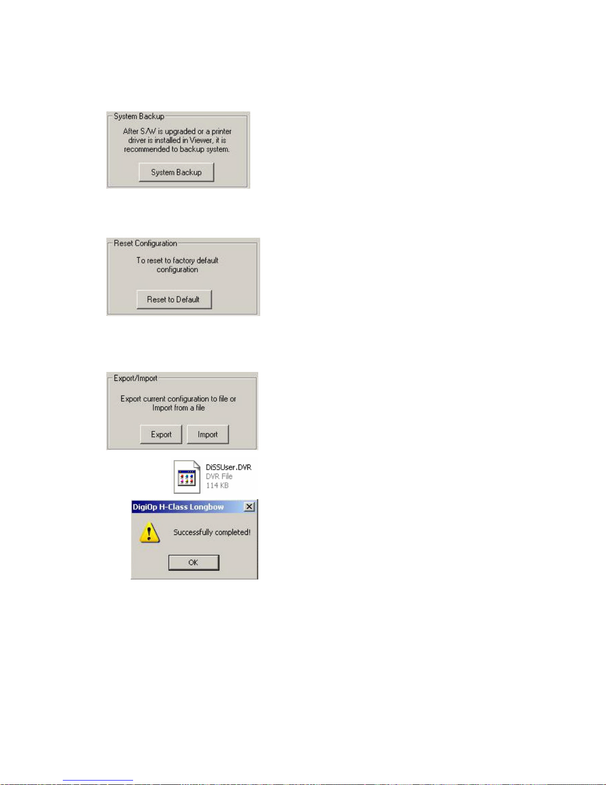
DigiOp Installation Manual
Page 82 of 115
System Backup
Whenever any changes are made to the system or its
configuration, it is mandatory to create a system backup
by pressing this button.
Unless a system backup is completed, the next time the
system experiences a power cut or software failure, the
Digi Op DVR will restart from the most recent system
backup.
Reset Configuration - Reset to Default.
This wipes the User settings and restores the factory
default settings for this machine. All user- defined
settings will be lost.
Export/Import System Configuration
If multiple machines are to be configured in a similar
manner, the configuration from one machine can be
saved to an external storage device ( e.g. USB memory
device) and transferred to another similar machine
where that same configuration can be imported.
The file is not sufficiently large to cause any issues for a
floppy drive disk.
A message will indicate when the file has been
transferred.
Note: Export/Import does not export/import Users or IP data. To export/import Users go
to the DISPLAY tab.
Page 83

DigiOp Installation Manual
Page 83 of 115
Email Notification
To activate this option, check the “Email
Notification” check box (NOTE: This assumes your
LAN supports e-mail).
• Enter a DVR Location as descriptively as
possible. This description differentiates this
DVR from all DVR’s.
• Enter the recipients email address into the
“Send to” text box in the correct format (e.g.
security.manager@business_office.com). For
testing purposes, enter a local email address
just for initial setup.
• Under the “Email Setting” menu, enter the
sender’s email address. (This will appear on
the email as a response contact.)
• The “Host Server Address” is the email
server on the network (refer to your IT
Administrator if necessary).
• If authentication is required, check the “Need
Authentication” check box and fill in the
details.
• Using a local “send to” email address, click
the “Email Test” button to confirm an email
can be sent and received successfully .
Select Events
Emails are sent to the recipient bas ed on the criteria selected in the “Select Events”
options list. The options are:
System (and/or options)
- Recording Start
- Recording Stop
- Exit Application
- Hard Disk Fail
- Video Loss
- Time/Date change
- System restart
Remote Events – Connection and/or Disconnection from Remote PC applications (e.g.
RemoteManager, Cardax, etc)
User Events – Login and/or Logout of a DVR Operator
I/O Events – Sensor and/or Motion Sensor and/or Control (i.e. any I/O or Motion
Detection change of status).
Page 84

DigiOp Installation Manual
Page 84 of 115
The Event Selection Window enables
the user to select multiple events by
checking the section e.g. SYSTEM
The email sent by the system will provide the following information, including an attached
JPEG of the channel that caused the event (see below).
Page 85

DigiOp Installation Manual
Page 85 of 115
Example: Setting up the SYSTEM EVENTS for Email Notification.
1. Open the Events by clicking
SELECT EVENTS button. The main
tree of events can be viewed.
2. To view options, click the ”Expand
tree” icon . Then press the un-
expand icon to return to main tree
directory of events.
3. Check the SYSTEM EVENTS
option check box.
4. Expand the SYSTEM EVENTS
option again to view the effect.
5. Deselect options not required to be
monitored (example only).
This will result in an email being sent to
the recipient any time one of the
checked events occurs.
1
2 3 4
5
Page 86

DigiOp Installation Manual
Page 86 of 115
Search
The SEARCH menu is a sub menu of the TOOLS menu.
This provides a convenient method to view, analyse (reprocess), manipulate and expor t in
different modes/formats.
Click TOOLS>SEARCH
By default the SEARCH mode will take you to the end of the current recorded files. These
are not updated with recordings taking place while the SEARCH menu is open.
Page 87

DigiOp Installation Manual
Page 87 of 115
Graphical Record Log
The 24 hour time period for the time and date selected is displayed across the top.
Double click (up to twice) to ‘zoom’ in on the time line and to expand the view.
Clicking anywhere on the time-line will cause the Scan Bar to move to that position/time.
The Record Hour/Minute display and the Scan Bar are
synchronized so that a change in either one will always be
reflected by the other.
Scan Bar (quick search cursor line)
You can click and drag the Quick -Search slider (or the Scan Bar itself) to
rapidly move the Scan Bar forwards or backwards along the time-line.
The preview pane displays the images as soon as the files are accessed.
By double clicking the time line, the time line will be zoomed in for greater
incremental searching.
Current Date and Time
The PC’s current date/time is displayed for reference at
the top right of the Search screen.
Doub
le click to
zoom timeline
Click + or
-
to
incrementally
move Scan Bar
Page 88

DigiOp Installation Manual
Page 88 of 115
Search record Date and time
This section is to locate recorded data. Use the
calendar to click on the desired search date. Use
the “Prev” or “Next” links to move to last month or
next month.
The calendar digits are highlighted
to identify there are recordings for that date.
Yellow digits identifies the date currently
selected, greyed digits indicate no recordings
exist for that date.
Use the Up/Down arrow buttons to adjust the
YEAR and MONTH if preferred
Use the HOUR and MINUTE Up/Down arrow
buttons to locate known records. . This
section is synchronised with the Scan Bar so any
change to the Scan Bar position will be reflected
here.
Camera selection and camera list scrollbar
The images can be represented in various multi screen division modes
(4, 9,16) or as a single record image (1). Each camera can be individually
selected by pressing the Camera description down the LHS of the
graphical log. Cameras not selected will not be visible.
In the single image mode, use the camera selection buttons to move the
displayed image from one camera to the next. In the multi division screen
mode, use the camera selection buttons to select, or de-select (the
inclusion or exclusion ) each camera from the search/display.
The scroll bar can be used to access the other cameras not shown (8-16).
Playback Controls
Move to end of available files
Frame by frame step forward
Play forward at selected speed
Pause/Stop
Reverse play at selected speed
Reverse frame by frame
Move to beginning of day files
Page 89

DigiOp Installation Manual
Page 89 of 115
Playback speed control
The Speed slider control provides forward or
playback at speeds of 1/8, ¼, ½, 1, 2, 4, 8 x realtime speed.
To adjust playback speed, either drag the slide tab
or click on the slider bar.
Screen division display modes
Click the appropriate icon to switch from 1, 4, 9, or
16 images. Individual images can be removed
from the split screen by clicking the camera button
(left of the graphical record log).
The selected mode will highlight on selection.
Still Image Zoom button
Clicking this button will incrementally zoom into an
image on the screen . There are 48 zoom steps by
pressing the right mouse button. Place the mouse
over the image to zoom into and the mouse cursor
changes to the +/- magnifying glass type. Clicking
the left mouse button will zoom out to 1:1 ratio. By
positioning the mouse on different parts of the
image before clicking, various parts of the image
can be zoomed into (i.e. the zoom does not need
to be centralized).
No zoom Maximum zoom
Page 90

DigiOp Installation Manual
Page 90 of 115
Interlace/De- interlace button
This is only applicable on the EDNS4/6000 DVR’s
when processing 4CIF recorded data, normally
while processing images for printout.
Note: 4CIF images are interlaced. When printing
an image where the source was a dynamic
(moving) image, the unit captures “Even” and
“Odd” fields to create the frame. Greater clarity
may be gained by viewing these fields separately..
The de-interlace button provides a way to view the
EVEN and ODD fields of a frame. The default
image is the interlaced image. Press the deinterlace button once for the EVEN fields, press it
again for ODD fields, and press it again for the
default image . The selected field can be viewed
during playback or while an image is still.
Interlaced
frame
“Even” field
“Odd” field
Interlaced fast
moving image
(zoom)
Odd
field of the
same
fast
moving image
(zoom)
Page 91

DigiOp Installation Manual
Page 91 of 115
Save Searched Images Button
This button provides access to the various save images options (other then HOUR
BACKUP). It provides:
• Video Backup (DSF format and viewer)
• Still Image Backup
• Standard format (save MPEG video)
Video Backup Button
• Select the camera/s that are required for
backup by checking the associated
camera checkbox.
• Select the Start Date and Time and the
finish Date and Time (use the drop arrow
to bring up a full selection calendar).
Press the ADD button to add this
selection to the backup list.
• Repeat this process for other backup
selections. Each time press the ADD
button.
• The saved video is the encrypted DSF format. If required a viewer can be included
that enables the saved images to be viewed from the back-up media. If the viewer
is desirable, check the “Automatic Playback from CD” option.
• Select the “Backup Location” from the drop down list. Backup must be to a
CD/DVD, Removable drive, or Network device. The system will scan the selected
drive and display the available free space.
• From the “Backup Period List” select one or more periods to backup on the media
you have available. The file size of the selected cameras and dates/times will be
displayed under the SPACE information.
• Once the selections have been made, press the Start Backup button. The system
will display the save progress as it happens on the line graph.
Page 92

DigiOp Installation Manual
Page 92 of 115
Still Image Backup (BMP or JPG)
• Pause the playback.
• Select the camera you wish to save.
• Select the format you would like to save
the image as (BMP or JPG).
• Use an external storage device e.g.
memory stick, for file storage. Define the
“File Path” by clicking the Open Folder
Browser icon .
• Select the location from the browser.
• Define the number of frames to save by
using the Up/Down arrows on the
“number of frames” selector.
• If using a CD that requires formatting, click
FORMAT CD button
• Click the SAVE button to start the
conversion/saving process.
Standard Format – MPEG Video Backup (minutes)
This option saves video to either a CDROM or a Network Drive.
• Pause the image at the approximate point
where the video save sequences should
start.
• Use the Camera drop down menu to select
the camera to be saved
• Use an external storage device (e.g.
CDROM, DVDROM, memory stick, USB
drive, External HDD, or NAD) for file
storage. Define the “File Path” by clicking
the Open Folder Browser icon .
• Select the location from the browser.
• Using the Up/Down arrow buttons ,
define the START minute of that hour and
the FINISH minute of that hour.
• If using a CD that requires formatting, click
FORMAT CD button
• Click the SAVE button to start the
conversion/saving process.
Page 93

DigiOp Installation Manual
Page 93 of 115
SEARCH TOOLS menu
A range of manipulation, video analysis, and storage
options are available under the TOOLS menu.
Image Adjust
This is for adjusting the playback of a video record.
Select the camera to manipulate
from the “Camera Num” drop-
down menu. To change a
number of cameras, select each
one, one at a time and adjust
the settings to suit.
Select any one or more “Image
Filter” options. The image will
be adjusted according to the
filters chosen.
Adjust the BRIGHTNESS as
required (real time preview
update).
Adjust the CONTRAST as
required (real time preview
update).
Press PLAY to view the video record.
To restore (normalize) the image again, click the INITIALIZE button and this will revert all
settings back to their default values.
POS (Point of sale)
This is also known as the DTM (Data Transaction Manager) and requires another license
as it is not included in DVR pricing. Please contact your DigiOp supplier for details.
Page 94

DigiOp Installation Manual
Page 94 of 115
Configure
The Search>TOOLS>CONFIGURE menu option provides three functions;
Add Printer
Use this option to add Windows
compatible printers. Ensure the
number of installed printers is
kept to a minimum as there is
limited HDD space available on
the OS drive. Once the Printer
is added, go to the
TOOLS>CONFIGURE> System
tab and do a BACKUP.
Click the ADD PRINTER button
to browse for the printer file/s.
Search Option
This option is used in the Viewer Search application. It
will simply search a CD for DSF video files and display
them on the timeline.
Volume Control
This control allows you to adjust the playback audio
volume.
Page 95

DigiOp Installation Manual
Page 95 of 115
Search Sensor Events
When this menu option is
selected, the currently
selected date is scanned by
the DVR to produce a list of
all sensor events for the
selected camera. List items
are displayed in the format
shown (Time, Event Type,
Sensor Number).
Use the Camera Number
drop down list to select
which camera to view.
To review the PREVIOUS
or NEXT date, click the
appropriate button. You will
be prompted with a
message if there is no
previous/next date.
If the User is using a multi division screen, all the camera views will be updated to closely
match the date/time of the camera being searched. The Graphical Time Line will be
updated.
Print
Once the User has completed a search using the search tools and the images to be
printed are located. ..
Select the PRINT option on the Search TOOLS button
menu
Select the camera(s) for which images are to be
printed. A disabled checkbox indicates that that
camera has no recorded images for that date/time.
If a local or network printer is connected, these camera
images will print. If the DVR has not been configured
with a default printer, the Windows printer connection
wizard will pop up to assist with the connection of a
printer.
Page 96

DigiOp Installation Manual
Page 96 of 115
Hour Backup
This option will save DSF files to backup storage
media. DSF files are saved in one-hour increments
and are not decrypted.
1. Open Search>TOOLS>Hour Backup menu
option. (The “Backup” window opens.)
2. Select the date to backup on the “Select
Backup Date” drop down menu.
3. Select a camera(s) from the CAMERA
NUMBER list (use the CTRL key to select
multiple cameras).
4. Select an hour/file(s) from the HOUR list (use
the CTRL key to select multiple hours/files).
5. The total estimated storage requirement for
the selected files is displayed under
“Selected file size”.
6. Select the location to save the file to by
clicking the Open Folder Browser icon . If
saving to a CD/DVD, use the Format DVD
RAM or Format CD buttons.
7. The available storage capacity of the
selected path is displayed under “Target free
space”.
8. Click SAVE to save the files. The files and a
DSF viewer will be saved to the specified
storage location .
Page 97

DigiOp Installation Manual
Page 97 of 115
Smart Search
o
o
The SmartSearch (also referred to as “IntelliSearch” or “Museum Search”).
This mechanism provides post-recording movement analysis of video content.
“Motion sensitive regions” are created by the Operator on a recorded camera image
selected from the available recorded files. The image is viewed on the screen to which
the motion sensitive areas can be drawn directly onto the image. Any activity that
compromises these regions (sensitive level adjustable) will create an ‘event’ reference in
the associated list.
Example: Say the cameras are using the “mo tion detect ion” recording mode on a parking
lot scene. The Operator wants to know the times a certain lot was entered or exited. The
SmartSearch feature enables a specific region(s) on the recorded image to be clearly
defined, then reviewed to automatically identify any motion in those regions.
Page 98

DigiOp Installation Manual
Page 98 of 115
Procedure:
1. On the main search screen, select the date/time to start the search at.
2. Select the camera to be analysed by clicking on the image (border will highlight)
3. Select the SMARTSEARCH option from the Search>TOOLS menu.
4. The above window appears which confirms the camera and the date and time of
the search.
5. In the SEARCH options, enter the start and
end times for the search. You can use the
File Begin and File End checkboxes to set
the start and end times to match the
available file content.
6. Click the “Go to start” button to view the
start point selected.
7. There are two available options for defining search regions:
a. “Block” creates a fixed-size square on the image. Up to
20 horizontal and 15 vertical blocks can be added to the
image by simply clicking on the image in the desired
location.
b. “Square” creates a User-defined rectangle. Simply click
on the image, then drag the mouse to define a “square”
region.
Multiple squares and rectangles can be created on a single
image to create the motion sensitive regions required.
Blocks and squares can overlap.
8. Select the MOVE option to click on a Block or a Square
and move it to a new location.
9. Select the DELETE option to click on a Block or Square
and remove it .
Block
Square
Page 99

DigiOp Installation Manual
Page 99 of 115
View Search Process (during SmartSearch)
Check the "View Search Process" check box to
view all video. When this option is unchecked, only the images
that compromise the defined movement sensitive Squares or
Blocks at the sensitively level selected are previewed. If no event
is found, the image will not change.
Sensitivity (for SmartSearch)
The sensitivity slider can be adjusted between zero (not sensitive
to movement) and 100% (very sensitive to any changes in the
defined regions). Set this value depending on the amount of
movement you wish to be detected before an event is triggered.
The number of events appearing on the event log will reflect the
sensitivity of the regions i.e. 100% sensitivity will return more
events.
SmartSearch - Search
By default the DVR will open with the START TIME
as the beginning time of the first recording for that
camera, that day (initially the same as “File Begin”
time). The END TIME is the time of the end of the
file (initially the same as “File End”) when the
SMARTSEARCH menu was opened (i.e. does not
update real time).
• These two times can be adjusted to a more defined period
by using the up/down arrow buttons, or directly editing the
numeric in the boxes.
• Click the “Go to Start” button to see the image at the start
of the selected period.
• To ignore the defined START TIME and/or END TIME and
redefine to the file beginning and/or file end, check the
FILE BEGIN and/or FILE END check boxes. The
appropriate START or END text box will grey out indicating
the override selection.
Quick Search
The Quick Search feature simply speeds up the process. During
casual test ing a 10 minute recording processed 20% faster with
Quick Search selected. Seach times are typically 60 seconds per
10 minutes of video. In effect the Quick Search ONLY reviews the
“index” images and ignores the other images. In a realitively
motionless scene this option could save considerable search
Page 100

DigiOp Installation Manual
Page 100 of 115
time. If the Quick Search option not selected, DigiOp will review
every image recorded.
Start the SmartSearch Process
Search Next Movement
Click the “Search Next Movement” button to start the
search. The search will pause at the first event (i.e.
movement detected inside a defined sensitive region). The
found event appears on the list with the start and stop time
of the event. Click again to move to the next search.
Search All
The “Search All” button will erase the current search event list and start the search from
the beginning again . The search can be stopped but not paused. Events will be listed by
start/end times.
Stop Search
The “Stop Search” button terminates the search completely (no pause option is available).
 Loading...