

Page 1

INSTALLATION INSTRUCTION FOR PIR-150
2824-00002 Page
1
I
NSTALLATION INSTRUCTION
1. Introduction
The PIR-150 is a highly sensitive Passive Infrared Detector designed for long range detection outdoors with a
narrow, curtain-shaped differential field of view. It incorporates adaptive threshold discrimination by
feedback of environmental effects and rejection of disturbance signals, temperature compensation, flat
frequency response and a computer designed optical system for uniform curtain coverage.
The gain can be adjusted with a potentiometer to adapt t he sensitivity of each individual unit in f unction of
the required detection range and according to the specific needs of an installation. Depending on the type
of installation, emphasis can be put on maximum detection or lowest nuisance alarm pr obabilit y .
2. Mounting and Installa t i on
The mounting structure should be stiff enough to resist significant deflection in windy conditions.
Movement of the PIR-150 caused by vibrat ions or ot her m oveme nts w ill res ult in large s wings of t he f ield of
view covered by the PIR-150 and could cause strong disturbance signals. These unwanted signals may lead
to an increase of the alarm threshold level thus reducing the responsiveness or in certain cases producing
unwanted alarms.
It is very important that the back cover of the PIR- 150 is securely tightened. It is not sufficient to close
the cover only to the point where the O - ring starts to rub against the inside of the cover. It must be
tightened to the point where it cannot be closed further with reasonable force. There will then be
hardly any gap between the cover and the housing (considerably less than 0.5 mm) .
The cable entry assembly should not be changed without authorisation by the manufacturer . It is specifically
designed to allow air entry and exit so that the inside of the PIR-150 is alw ays at atmospheric pr essure. This
prevents moisture being sucked into the PIR-150 by drop of internal pressure likely to happen when rainfall
rapidly cools down a unit warmed up in the sun.
The nut on the cable entry assembly should be tightened to clamp the cable in place with the nylon grip. If
the cable diameter is too small to be held by the grip, insulation tape should be wound ar ound the cable to
increase the outside diameter to a suitable size.
3. Connecting the PIR-150
For the definition of the connector board and terminal block see Annex 1.
Alarm Signalling
There are two types of alarm signalling from the PIR- 150:
one set of SPDT potential-free relay contacts
an open collector transistor to negative supply rail
The relay contact changes state and the transistor switches to low resistance on alarm.
Tamper Switch
To detect attempts to open the PIR-150, a tamper switch is fitt ed for the rear cap. Its contact opens when
the cap is unscrewed and can be connected in series with the normally closed r elay contact if no separa te
tamper line is used.
Electronics Supply
Ensure that polarity is correct when connecting power to the electronic circuit. Built-in circuitry will
withstand a short period of re v e r s ed polar ity, but damage will result if this is not corrected quickly .
Page 2
INSTALLATION INSTRUCTION FOR PIR-150
Page
2
2824-00002
4. Field of View
The PIR-150 has a curtain-shaped field of view formed by differential detector zones for long to short range
detection. Their relative sensitivity is balanced in function of their respective range for the recommended
mounting height of 2.5 to 4.0 m. The vertical opening angle is app. 25° resulting in an uninterrupted
curtain starting at app. 8 m with the PIR-150 mounted at 4.0 m height and aligned f or a det ection range of
100 m (Fig. 1).
The mounting should be done in a way to allow easy horizontal and vertical alignment while giving the
required long term stability .
5. Alignment
The detection range of a PIR detector is not limited but a function of size, speed and temperature contrast
of a target against its background. The PIR-150 should be aligned so that the field of view is t erminated by
a natural or artificial background at the end of the range.
Where a terminating screen is used its surface should not be glossy to avoid reflected images from outside
the field of view. Also the material may be transparent for visible light but it has to block thermal radiation;
wood, poly-carbonate and acrylic are suitable materials.
Effectiveness of a screen has to be checked by walk testing around the screen. Signals from walk tests in
front of the screen should still be st rong while movements behind the screen should result in signals well
below the threshold level. If walk tests or vehicles passing behind the screen ar e strong enough to trigger
an alarm the PIR-150 should be tilted slightly downward. The Installation Tester IT 44 gives accurate
information about signal strengths during a test .
Coarse alignment can be done visually by looking along the grove on top of the detector. Accurate fine
alignment is easily achieved with the help of the Universal Telescopic Sight ZA P 03 which can be placed on
top of the PIR-150 for this purpose.
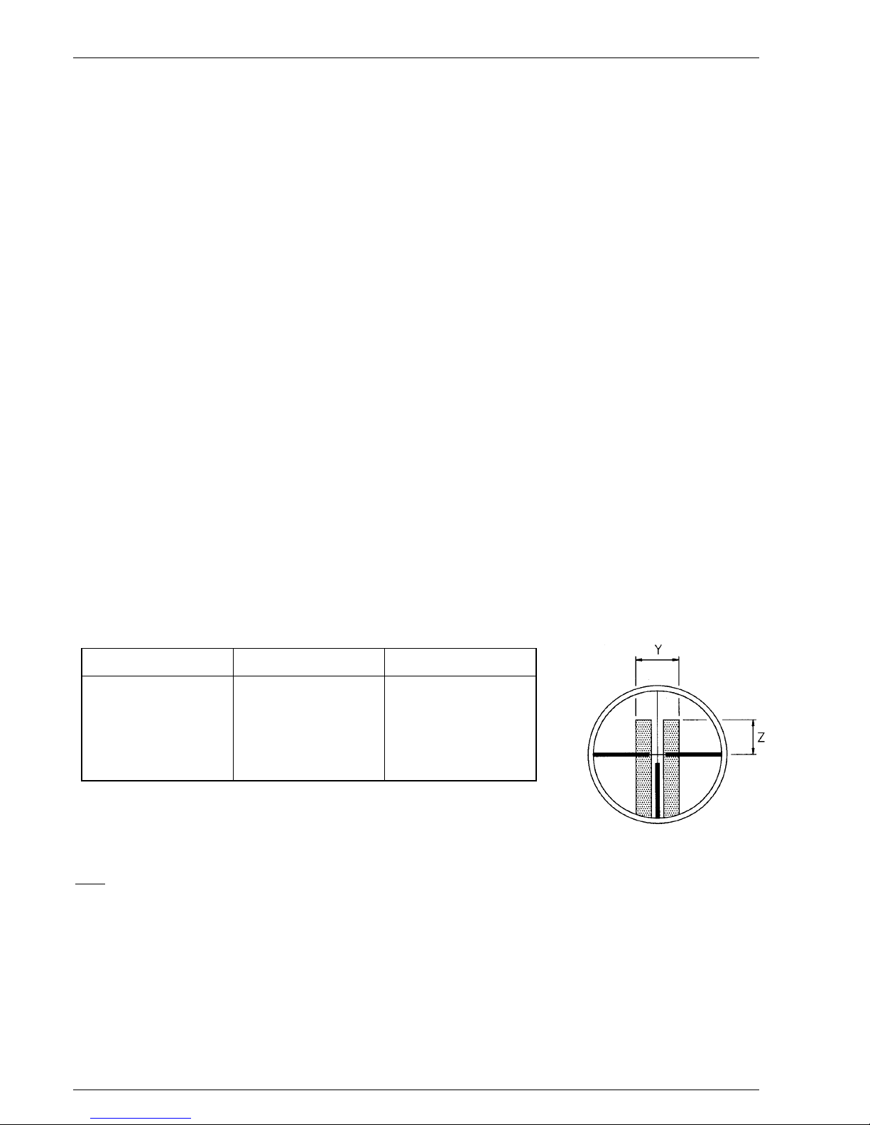
The graticule of the ZA P 03 corresponds to the axis of the detector. The detection curtain extends f rom +
1.2° to - 25° in the vertical plane from the axis of the detector. Table 1 show s the elevation (Z) of the upper
edge of the field of view from the axis and the total width ( Y) of t he f ield of view as a function of t he actual
distance from the PIR-150.
Table 1
Note: The dimensions „Y“ and „Z“ are calculated figures verified by experiments. Actual dimensions
will vary with contras t conditions.
Distance X Total width Y Elevation Z
25 m 0.6 m 0.5 m
50 m 1.3 m 1.0 m
75 m 1.9 m 1.5 m
100 m 2.5 m 2.0 m
125 m 3.1 m 2.5 m
150 m 3.7 m 3.0 m
Page 3
INSTALLATION INSTRUCTION FOR PIR-150
2824-00002 Page
3
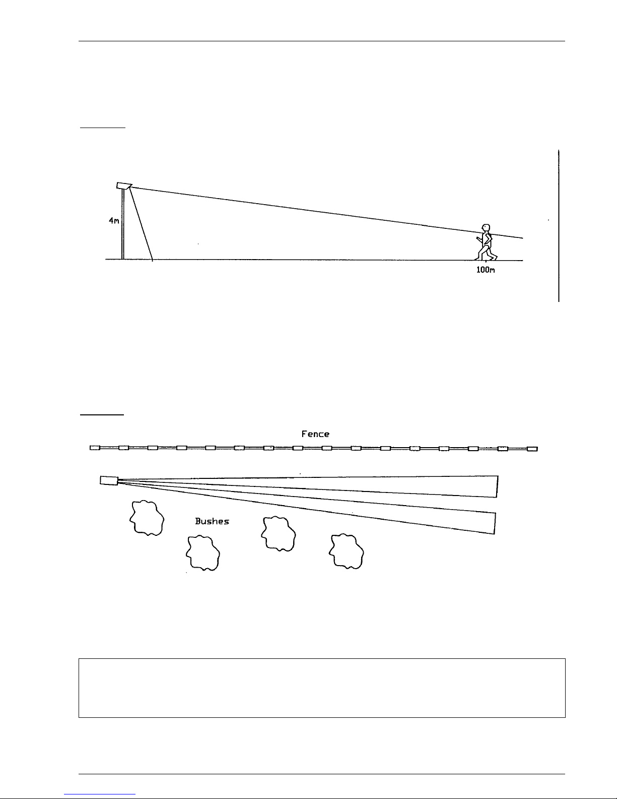
Typical vertical alignment for a required detection range of 100 m
The PIR-150 should be aligned vertically so that at least the lower half of a person st anding upright at the
maximum required range will be within t he f ield of v iew ( s ee F ig. 1 below).
Side view
Fig. 1
Typical horizontal alignment
Horizontal alignment should be done in a way to avoid unwanted signals being generated by targets
(branches, bushes, fences) likely to be moved by wind (see Fig. 2 below). Movement within the field of view
will reduce the sensitivity of t he PIR-150 by increasing the alarm threshold level or may lead t o unwanted
alarms.
Top view
Fig. 2
The ZA P 03 alignment telescope is a convenient alignment aid giving a high degree of accuracy for initial
installation. It is nevertheless important to verify correct alignment by monitored walk tests across the field
of view.
When walk testing the unit the threshold level will increase as a result of the signal generat ed by the
target. To make sure that original sensitivity is reached, wait at least for 1 minute between each
crossing or disable the Adaptive Threshold Discriminator (ATD) by closing the swit ch on the connector
board.
If the Installation Tester IT 44 is used for monitored walk tests, the instantaneous threshold level will be
displayed.
Page 4
INSTALLATION INSTRUCTION FOR PIR-150
Page
4
2824-00002
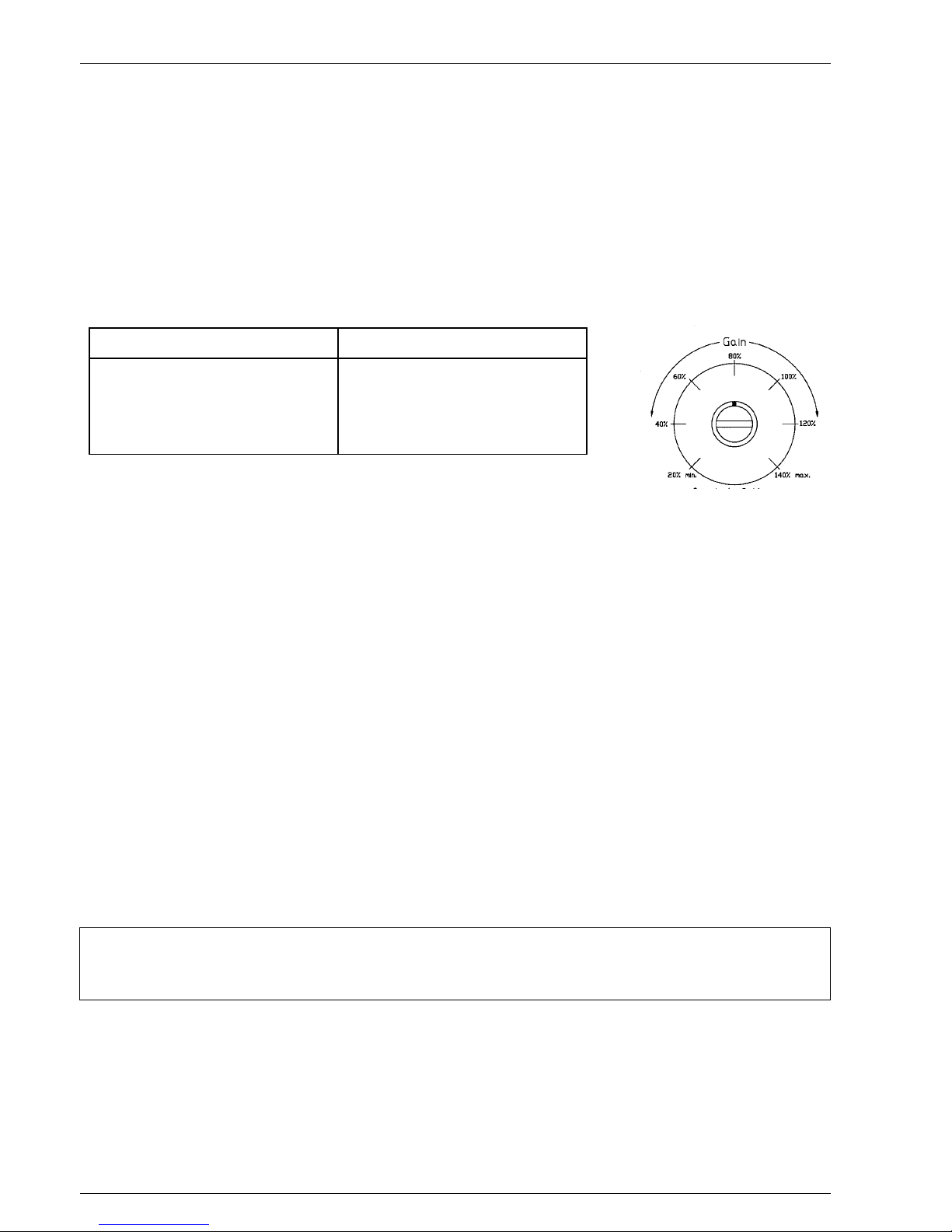
6. Sensitivity Adjustment for Range
The sensitivity of the PIR-150 is adjusted by means of a potentiometer w ith an adjustment range from 20 t o
140 % of nominal sensitivity. It is normally not recommended to set the gain adjustment higher than 100
% even for the full range unless an increased number of nuisance alarms can be tolerated in exchange for a
maximum detection probability .
The PIR-150 is designed to detect human targets to distances up to 150 m under most environmental
conditions. For an optimum detection to nuisance alarm ratio it is recommended to limit the detection
range to 100 m and set the gain to app. 80% of nominal (factory set t ing).
Recommended settings of the sensitivity gain control as a funct ion of required detection range ar e shown in
Table 2 and are as follows:
Table 2
The PIR-150 is designed for mounting at heights between 2.5 and 4.0 m
above ground. Lower or higher mounting will lead to s ub-optimal balance of the detect ion curtain and lead
to detection gaps or excessive nuisance alarms.
Vertical alignment is optimal when the upper edge of the f ield of view is at 1. 5 to 2.5 m above ground at
the end of the required detection range provided that the f ield of view is properly t erminated. Setting the
detection range as specified above does not limit the range but reduces the sensit ivity of the w hole curtain.
Targets moving at the lower limit of the specified speed at the end of the range will pr oduce relat ively w eak
signals.
7. Alarm Time
The alarm time depends on the shape and amplitude of the alarm signal and can be as short as app. 0.2 s.
If a signal is very strong the PIR-150 may generate a longer or sever al alar m pulses f or t he same event .
If required by the application the alarm time can be extended by up to 10 seconds per event with a
potentiometer on the connector board.
8. Internal Temperature Compensation
The PIR-150 is detecting radiation differences of a target against its backgr ound. In the course of the day
and year the contrast of a person will vary c onsiderably and affect the signal strength. To com pensate for
this contrast variation, the PIR-150 has an internal temperature compensation w ith maximum sensitivity at
app. 30°C (where the contrast of a human target is weakest) and gradual reduction at higher and lower
temperatures.
When installing a unit the internal temperature may take up to 30 minutes or more to stabilise to the
actual external temperature. Sufficient time should be given to the PIR-150 to reach the correct
internal temperature and sensitivity before walk t est s ar e done.
During the initial period of operation it is strongly recommended that walk tests are repeated and signals
monitored under various weather conditions such as high and low temperatures, wind fog, snow, rain, etc.
to obtain comparative data and information on the effects of environmental conditions on detect ion and
nuisance alarm probabilities for t his particular site.
Potentiometer Setting Detection Range
70 - 140 % 100 to 150 m
50 - 100 % 80 to 100 m
40 - 80 % 60 to 80 m
30 - 60 % 40 to 60 m
20 - 40 % 30 to 40 m
Page 5

INSTALLATION INSTRUCTION FOR PIR-150
2824-00002 Page
5
9. Adaptive Threshold Discrimination (ATD)
The background noise is constantly averaged and fed into a special circuit changing the threshold level for
the alarm. This special feature is reducing the probability of nuisance alarms caused by wind, moving
vegetation or objects which have a thermal contrast although usually weaker than a person.
Every signal exceeding a certain minimum value will activate the ATD and increase the threshold level
depending on its strength. The time constants for increase and decrease ar e chosen in a way to adapt to
gradual changes. Signals generated by a person moving within the specified speed range are fast enough
for detection but will activate the ATD circuit as w ell. Repeated movement of any kind within the field of
view is therefore activating the ATD, reducing the overall sensitivity.
This has to be noted particularly when walk testing the PIR-150 following installation. For this purpose, t he
ATD circuit should be disabled by closing the corresponding switch on the connector board. Operation of
the PIR-150 in this mode is possible but not recommended in outdoor applications as the nuisance alarm
rate would increase significantly.
10. Internal Heater
A regulated heater which can be connected to the supply voltage of the PIR-150 or a separate DC or AC
supply of 12 to 24 Volts nominal prevents the optical surf aces from fogging or f rosting and maintains the
internal temperature at optimal levels. It is highly recommended always to operate the PIR-150 with the
heater connected as temporary loss of sensitivity or permanent damage could result from condensation
inside the detector.
11. Installation Tester IT 44
The Installation Tester IT 44 is very useful for alignment and signal check during setting up and routine
maintenance. It will indicate the amplitudes generated by wanted as well as unwanted targets and help
setting the gain control correctly during walk tests and show t he m agnit ude of dist ur bance signals.
The information displayed on an LCD once the Installation Tester is connected to the detector includes bar
display of signal amplitudes with peak hold feature, instantaneous threshold level as well as alarm time and
count. A separate description is available with more details.
12. Maintenance
The detector has been designed to be virtually maintenance free but the following precautions are
recommended:
1) Visual inspection of the front window for accumulation of dirt on the outer surface or damages at
intervals of app. 6 months. To clean the surface use a paper tissue and avoid rubbing dirt into the
surface. Use the same precautions as for a camera lens.
2) Visual inspection of the inside for ingress of wat er is recommended at int ervals of 6 t o 12 months or
whenever the unit is opened for adjustments or tests. Make sure that the sealing rings are in place
before closing the back cover tightly again.
3) Inspection is recommended following extreme conditions such as snow storms, sand storms, hail
etc. to make sure that nothing has been damaged and the sensitivity is not reduced by accumulation of
snow, sand or dirt on the front window. Snow or dust in front of the window should be removed by
hand or the use of a soft instrument such as a wooden stick.
Page 6

INSTALLATION INSTRUCTION FOR PIR-150
Page
6
2824-00002
13. General Comment on the PIR-150
Despite the advanced design and state-of-the-art features of the PIR-150 it is in the nature of a Passive
Infrared Detection System that an absolute detection probability and freedom from nuisance alarms
cannot be achieved,
masking of the PIR-150 cannot be excluded
.
Detection is a function of thermal contrast, speed and size of a target crossing the f ield of view. Contrast
conditions can vary significantly in the course of the day and year.
Detection depends also on the sensitivity settings, the exact aiming and the prevailing weat her condit ions
as well as the nature of the target and background.
The detection pattern and frequency response of the PIR-150 have been optimised for the detection of
human size targets crossing the field of view in an upright position at speeds in the range of 0.2 … 5.0
m/s.
Detection of slow moving targets at long range may become uncertain under w eak contrast conditions.
It is strongly recommended to limit the zone length to ma x. 100 m when human targets moving at the
minimum specified speed need to be detected wit h high pr obabilit y .
Animals or crawling people may or may not be detected depending on their size, speed, contrast and
distance from the PIR-150.
It is therefore strongly recommended to combine the PIR-150 with an alarm verification such as CCTV or a
second system using other physical means of detection.
Any liability for direct or indirect damage resulting f rom the use of the PIR-150 as a detection device are
explicitly disclaimed.
The information in this product manual is based on testing of samples taken at random from production
and believed to be representative.
Page 7

INSTALLATION INSTRUCTION FOR PIR-150
2824-00002 Page
7
14. Specification:
Nominal Range: 100m (330 ft)
Spectral Response: 8-14 micrometres, double filtered
Sensor: Differential pyro-electric array
Alarm Output: SPDT relay, 3W, 0.25A, 28VDC/20VAC Transistor, NPN
open collector, 20mA/30V
Output Protection: PTC resistor
Alarm Indicator: Internal LED
Alarm Hold Time: 0.2-10 seconds, adjustable
Sensitivity Adjustment: 20-140% of nominal
Temperature Compensation: Gain control 40-100%
Target Speed: 0,2 – 5 m/sec.
Internal Switches: Adaptive threshold system on/off
Supply Voltage: 10.5 to 28 VDC (nominal 12VDC)
Supply Current: Typ. 20 mA at 12VDC (without heater)
Heater Power: Approx. 1 W at –40°C
Operating Temperature: -40°C to 60°C (-40°F to 140°F)
Sealing: Splash proof to IP64 (cable entry spray proof to IP53)
Weight: 1.2 kg (2.6 Ibs)
Dimensions: 314mm long x 89mm diameter (13”x3.5”)
Cable Feedthrough: Cable diameter 6-14mm (PG16)
Cable Termination: Screw terminals
Mounting: UBP-150, Universal mounting bracket (optional)
Test Socket: For connection to IT44 Install. Tester
Page 8

INSTALLATION INSTRUCTION FOR PIR-150
Page
8
2824-00002
Annex 1: Connector Board and Terminal Block
The relay is shown in energised, non - alarm state.
ATD is activated when switch
is open
(close switch for walk tests only!)
Connector Board
Terminal Block
Page 9

INSTALLATION INSTRUCTION FOR PIR-150
2824-00002 Page
9
Annex 2: Instructions for Terminat ing Screens and Ground Surface
Introduction
The detection range of a PIR detector is not limited but a function of size, speed and temperature contrast
of a target against its background. Alignment of the detectors should be carried out in such a way that the
field of view is terminated by a natural or artificial background at the end of the range. Ref lections from
inside or outside the field of view have to be avoided as well as possible.
Definition of Field of View
The numbers stated in the technical manual for the vertical and horizontal dimensions are defined – per the
usual standards – as the half power points representing 50% of the relat ive sensitivity at that distance for a
typical human target. Absolute signal amplitudes depend on temperature contrast, speed and size of a
target and can be up to 20 times (and more for large vehicles) higher than the alarm threshold. For a strong
signal the dimensions will appear to be increased compared to the nominal values. This needs to be
considered when dimensioning a terminating screen.
Dimensioning a Terminating Screen
From the field of view definition it becomes clear that the width of a terminating screen has to be larger
than the actual figures given in the technical manual, this particularly when a street crosses the field of view
behind the screen.
A practical factor for the width of a screen is
1.5 times the width Y
of the field of view at the distance
from the detector.
The considerations for the vertical dim ension are similar although a certain installation flexibility is given by
tilting the unit slightly downward with the risk of losing sensitivity in the uppermost part of the curtain.
Therefore it is recommended to extend the screen also vertically in the same way using the same factor of
1.5 times the elevation Z
.
Example
: Screen at 100 m for a curtain height of 4 m with a PIR-150 ( s ee Table 1)
Width Y 2.5 m Screen Width 3.75 m
Elevation Z 2.0 m Screen Height Above Axis 3.00 m
Total screen height = curtain height - elevation Z + screen height above axis
This results in
minimum
dimensions of
3.75 m wide by 5.0 m high
(4.0 m - 2.0 m + 3.0 m) for the
terminating screen.
0 20406080100
1 m
2 m
3 m
4 m
m
Z
Axi
s
Typical side view of a terminating screen in 100 m distance from the detector. The dimension „Z“ is app.
2.0 m corresponding to the value of the table in section 5.
Page 10

INSTALLATION INSTRUCTION FOR PIR-150
Page
10
2824-00002
Required Properties of a Terminating Screen
The material of the screen has to block the therm al infrared radiation in the first place. Additionally it should
be non-reflecting and thermally insulating to avoid unwanted signals from reflected heat sources and
secondary radiation from strong sources heating up the screen f r om behind.
Since smooth surfaces – although dull for visible light – reflect the longer wave-length radiation of the
thermal infrared much better, a rough or st r uct ur ed sur f ace has t o be used.
Wood has all the required properties if the surface is treated according to the recommendation but almost
any plastic material would be suitable. If in doubt about thermal t ransmission verify the performance with
tests or consult the manufacturer.
Reflections from Screen and Ground Surface
Special attention has to be taken to possible reflections from the rising or setting sun which may generate
strong signals together with fast moving clouds. In cases where the screen is fa cing sunrise or sunset at any
time of the year the top of the screen has to be tilted towards the detector to reflect the sun into the
ground.
The ground has to be as non-reflecting as possible even when wet, use proper drainage to avoid form ing of
puddles. Reflections from snow can not be avoided technically and an increased occurrence of nuisance
alarms while the ground is covered with snow has to be accounted for.
Recommended Screen Dimensions
The following table indicates recommended values for the dimensions of a te rminating screen in f unction of
the distance.
Depending on the nature of possible nuisance alarm sources behind the screen, larger dimensions have to
be chosen (e.g. sources with strong thermal contrasts like heavy vehicles, trains or aeroplanes) to avoid
unwanted alarms.
Distance X Recommended screen width Recommended screen height above axis
25 m 1.00 m 0.75 m
50 m 2.00 m 1.50 m
75 m 3.00 m 2.25 m
100 m 4.00 m 3.00 m
125 m 5.00 m 3.75 m
150 m 6.00 m 4.50 m
Page 11

INSTALLATION INSTRUCTION FOR PIR-150
2824-00002 Page
11
Annex 3: Installation Tester IT 44 and PIRScope
Introduction
The universal Installation Tester IT 44 is available as accessory for alignment, set t ing up and fault finding and
can be used with all analog or digital detectors. It is re com m ended for verification of all installations in order
to optimise the performance of the detectors.
The following describes the features of the IT 44 and the software pr ogr am f or signal display.
It is strongly recommended that the detection perf ormance of the detector is verified by using the IT 44
Installation Tester. The IT 44 is connected to the detector's test connector from which it r eceives power and
data without interfering with the detector' s oper at ion.
The IT 44 displays all relevant detector data on a 4 - line liquid crystal display (LCD) including signal
amplitudes with peak-hold and the alarm threshold level. This level is dependent on the amount of
disturbance signals including walk tests.
Connection / Reset
The IT 44 is supplied with a cable of app. 3 m length terminated with a 7 pole circular connector. An
adapter cable for connection to the detector's in line connector is supplied w it h the IT 44.
When connected to the detector the IT 44 will be powered, start operation and display the identif ication of
the Installation Tester „
IT 44
“ including its version (e. g. „V 0.2“) on line 1 as well as „
Analog Mode
“ on
line 3 for a short period of time. The same display will appear every t ime RESET is pr essed.
Liquid Crystal Display
The display is divided into 4 lines providing the following information:
Line 1: Signal and Peak Hold
Quasi-logarithmic bar display in 60 steps shows the signal strength. The peak amplitude of each signal
exceeding the internal noise amplitude by a certain value is maintained for app. 6 s.
Line 2: Alarm Threshold Level
Displays the instantaneous alarm threshold level in the same scale as in line 1. If the ATD of the detector is
enabled the alarm threshold level will be increased by s ignals c aus ed by t ur bulenc es and walk tests.
Line 3: Alarm Indicator and Counter
Displays „
Alarm ON
“ or „
Alarm OFF
“ and the number of counts since last reset (display of „
Count
:“ and
„0“ to „99“ or „–“ if 99 counts have been exceeded).
Line 4: Alarm Time
Displays the alarm time for each event with „
Time
“ and e.g. „
12.3 s
“. The alarm time depends on the
actual alarm duration plus the setting of the alarm time potentiometer.
Audible Alarm
The Installation Tester has a high efficiency sounder which allows checking of the installation by a single
person. This is engaged by operating the toggle switch on the side of the IT 44.
Digital Output
The digitised detector information is available on a RS 232 interface on a test connect or at t he side of t he IT
44 for display on a PC screen with the
PIRScope
software.
No attempt should be made to make other use of this connector without instructions.
Page 12

INSTALLATION INSTRUCTION FOR PIR-150
Page
12
2824-00002
Application of the IT 44
The IT 44 is a most useful tool for checking the alignment and sensitivity setting of t he detectors. It greatly
facilitates the optimisation of an ins t allat ion t o s uit a par t icular site.
The IT 44 is particularly helpful in situations where a detector is operated under conditions near the
recommended operating limits of height, det ection range and target speeds. The information supplied by
the IT 44 display should be used to monitor the detection performance of the detector and make
adjustments if required.
Depending on the site’s animal activity, vegetation moving in the wind and/or other sources of disturbance
it is possible that unwanted alarms occur. Monitoring and int erpr eting the inf orm ation supplied by the IT 44
will help finding the best solution either by adjusting the alignment and/or sensitivity of the detector or by
removing disturbance sources from within the field of view.
PIRScope Software for PIR-150
For Display of Signals on a PC Screen Using the IT 44 as Interface Unit.
Procedure
1. Connect the PIR-150 to power and connect the IT 44
2. Connect the IT 44 output with COM port of the PC
3. Load the file „PIRSCOPE.EXE“, enter language and number of COM port
4. Adjust display using the keys as defined on screen
5. Display will show signal amplitude (green), t hr e shold (red) and alarm output (yellow)
6. Press „H“ to save a display in the active directory. A file will be generat ed and s av e d as
„DDMMYYAB.BMP“ where AB are used for identification of files within one day.
Note
When walk testing the PIR-150 make sure that the
ATD (Adaptive Threshold Decoding) is
deactivated (switch closed)
, otherwise the detection will become poor due to gradual increase of the
threshold.
Running „PIRSCOPE.EXE“ under Windows may lead to problems therefore exit Windows and
start
computer under DOS
to run the program.
 Loading...