

ERNITEC MVINVR-08POE4MP-E Quick Start Manual

Network Video Recorder
Quick Start Guide
MVINVR-08POE4MP-E

Network Video Recorder Quick Start Guide
1
TABLE OF CONTENTS
Chapter1 Panels Description .......................................................................................................................... 6
1.1.1 MVINVR-08POE04MP-E ........................................................................................................ 6
1.2 Rear Panel ............................................................................................................................................ 6
1.2.1 MVINVR-08POE04MP-E ........................................................................................................ 6
Chapter 2 Installation and Connections ........................................................................................................ 8
2.1 Installation ........................................................................................................................................... 8
2.2 Hard Disk Installation .......................................................................................................................... 8
2.2.1 MVINVR-08POE04MP-E ........................................................................................................ 8
2.2.2 Other Models ...........................................................................................................................10
2.3 Connections ........................................................................................................................................12
2.3.1 Alarm Input Wiring ..................................................................................................................12
2.3.2 Alarm Output Wiring ...............................................................................................................12
2.3.3 Alarm Connection ....................................................................................................................13
2.3.4 Controller Connection ..............................................................................................................13
2.4 HDD Storage Calculation Chart .........................................................................................................14
Chapter 3 Menu Operation ............................................................................................................................15
3.1 Start up Your Device ...........................................................................................................................15
3.2 Activate Your Device ..........................................................................................................................15
3.3 Configure Unlock Pattern for Login ...................................................................................................16
3.4 Login to the System ............................................................................................................................17
3.5 Enter Wizard to Configure Quick Basic Settings ................................................................................18
3.6 Network Settings ................................................................................................................................18
3.7 Add IP Cameras ..................................................................................................................................19
3.8 Start Live View ...................................................................................................................................20
3.9 One-Touch RAID Configuration ........................................................................................................20
3.10 Recording Settings ............................................................................................................................21
3.11 Playback ............................................................................................................................................22
Chapter 4 Access by Web Browser ................................................................................................................24

Network Video Recorder Quick Start Guide
2
Quick Start Guide
About this Manual
This Manual is applicable to Network Video Recorder (NVR).
The Manual includes instructions for using and managing the product. Pictures, charts, images and
all other information hereinafter are for description and explanation only. The information
contained in the Manual is subject to change, without notice, due to firmware updates or other
reasons. Please find the latest version in the company website.
Please use this user manual under the guidance of professionals.
Legal Disclaimer
TO THE MAXIMUM EXTENT PERMITTED BY APPLICABLE LAW, THE PRODUCT DESCRIBED, WITH ITS
HARDWARE, SOFTWARE AND FIRMWARE, IS PROVIDED “AS IS”, WITH ALL FAULTS AND ERRORS,
AND OUR COMPANY MAKES NO WARRANTIES, EXPRESS OR IMPLIED, INCLUDING WITHOUT
LIMITATION, MERCHANTABILITY, SATISFACTORY QUALITY, FITNESS FOR A PARTICULAR PURPOSE,
AND NON-INFRINGEMENT OF THIRD PARTY. IN NO EVENT WILL OUR COMPANY, ITS DIRECTORS,
OFFICERS, EMPLOYEES, OR AGENTS BE LIABLE TO YOU FOR ANY SPECIAL, CONSEQUENTIAL,
INCIDENTAL, OR INDIRECT DAMAGES, INCLUDING, AMONG OTHERS, DAMAGES FOR LOSS OF
BUSINESS PROFITS, BUSINESS INTERRUPTION, OR LOSS OF DATA OR DOCUMENTATION, IN
CONNECTION WITH THE USE OF THIS PRODUCT, EVEN IF OUR COMPANY HAS BEEN ADVISED OF
THE POSSIBILITY OF SUCH DAMAGES.
REGARDING TO THE PRODUCT WITH INTERNET ACCESS, THE USE OF PRODUCT SHALL BE WHOLLY
AT YOUR OWN RISKS. OUR COMPANY SHALL NOT TAKE ANY RESPONSIBILITES FOR ABNORMAL
OPERATION, PRIVACY LEAKAGE OR OTHER DAMAGES RESULTING FROM CYBER ATTACK, HACKER
ATTACK, VIRUS INSPECTION, OR OTHER INTERNET SECURITY RISKS; HOWEVER, OUR COMPANY
WILL PROVIDE TIMELY TECHNICAL SUPPORT IF REQUIRED.
SURVEILLANCE LAWS VARY BY JURISDICTION. PLEASE CHECK ALL RELEVANT LAWS IN YOUR
JURISDICTION BEFORE USING THIS PRODUCT IN ORDER TO ENSURE THAT YOUR USE CONFORMS
THE APPLICABLE LAW. OUR COMPANY SHALL NOT BE LIABLE IN THE EVENT THAT THIS PRODUCT IS
USED WITH ILLEGITIMATE PURPOSES.
IN THE EVENT OF ANY CONFLICTS BETWEEN THIS MANUAL AND THE APPLICABLE LAW, THE LATER
PREVAILS
SURVEILLANCE LAWS VARY BY JURISDICTION. PLEASE CHECK ALL RELEVANT LAWS IN YOUR
JURISDICTION BEFORE USING THIS PRODUCT IN ORDER TO ENSURE THAT YOUR USE CONFORMS
THE APPLICABLE LAW. OUR COMPANY SHALL NOT BE LIABLE IN THE EVENT THAT THIS PRODUCT IS
USED WITH ILLEGITIMATE PURPOSES.
IN THE EVENT OF ANY CONFLICTS BETWEEN THIS MANUAL AND THE APPLICABLE LAW, THE LATER
PREVAILS.

Network Video Recorder Quick Start Guide
3
Regulatory Information
FCC Information
Please take attention that changes or modification not expressly approved by the party
responsible for compliance could void the user’s authority to operate the equipment.
FCC compliance: This equipment has been tested and found to comply with the limits for a Class A
digital device, pursuant to part 15 of the FCC Rules. These limits are designed to provide
reasonable protection against harmful interference when the equipment is operated in a
commercial environment. This equipment generates, uses, and can radiate radio frequency energy
and, if not installed and used in accordance with the instruction manual, may cause harmful
interference to radio communications. Operation of this equipment in a residential area is likely to
cause harmful interference in which case the user will be required to correct the interference at
his own expense.
FCC Conditions
This device complies with part 15 of the FCC Rules. Operation is subject to the following two
conditions:
1. This device may not cause harmful interference.
2. This device must accept any interference received, including interference that may cause
undesired operation.
EU Conformity Statement
This product and - if applicable - the supplied accessories too are marked with "CE" and
comply therefore with the applicable harmonized European standards listed under the
EMC Directive 2014/30/EU, the LVD Directive 2014/35/EU, the RoHS Directive 2011/65/EU.
2012/19/EU (WEEE directive): Products marked with this symbol cannot be disposed of
as unsorted municipal waste in the European Union. For proper recycling, return this
product to your local supplier upon the purchase of equivalent new equipment, or
dispose of it at designated collection points. For more information see: www.recyclethis.info
2006/66/EC (battery directive): This product contains a battery that cannot be disposed
of as unsorted municipal waste in the European Union. See the product documentation
for specific battery information. The battery is marked with this symbol, which may
include lettering to indicate cadmium (Cd), lead (Pb), or mercury (Hg). For proper recycling, return
the battery to your supplier or to a designated collection point. For more information see:
www.recyclethis.info
Industry Canada ICES-003 Compliance
This device meets the CAN ICES-3 (A)/NMB-3(A) standards requirements.
Network Video Recorder Quick Start Guide
4
Symbol Conventions
The symbols that may be found in this document are defined as follows.
Symbol Description
Provides additional information to emphasize or supplement
important points of the main text.
In
dicates a potentially hazardous situation, which if not avoided,
could result in equipment damage, data loss, performance
degradation, or unexpected results.
Indicates a hazard with a high level of risk, which if not avoided, will
result in death or serious injury.

Network Video Recorder Quick Start Guide
5
Safety Instructions
Proper configuration of all passwords and other security settings is the responsibility of the
installer and/or end-us er.
In the use of the product, you must be in strict compliance with the electrical safety
regulations of the nation and region. Please refer to technical specifications for detailed
information.
Input voltage should meet both the SELV (Safety Extra Low Voltage) and the Limited Power
Source with 100~240 VAC or 12 VDC according to the IEC60950-1 standard. Please refer to
technical specifications for detailed information.
Do not connect several devices to one power adapter as adapter overload may cause
over-heating or a fire hazard.
Please make sure that the plug is firmly connected to the power socket.
If smoke, odor or noise rise from the device, turn off the power at once and unplug the power
cable, and then please contact the service center.
Preventive and Cautionary Tips
Before connecting and operating your device, please be advised of the following tips:
Ensure unit is installed in a well-ventilated, dust-free environment.
Unit is designed for indoor use only.
Keep all liquids away from the device.
Ensure environmental conditions meet factory specifications.
Ensure unit is properly secured to a rack or shelf. Major shocks or jolts to the unit as a result of
dropping it may cause damage to the sensitive electronics within the unit.
Use the device in conjunction with an UPS if possible.
Power down the unit before connecting and disconnecting accessories and peripherals.
A factory recommended HDD should be used for this device.
Improper use or replacement of the battery may result in hazard of explosion. Replace with
the same or equivalent type only. Dispose of used batteries according to the instructions
provided by the battery manufacturer.
Network Video Recorder Quick Start Guide
6
Chapter1 Panels Description
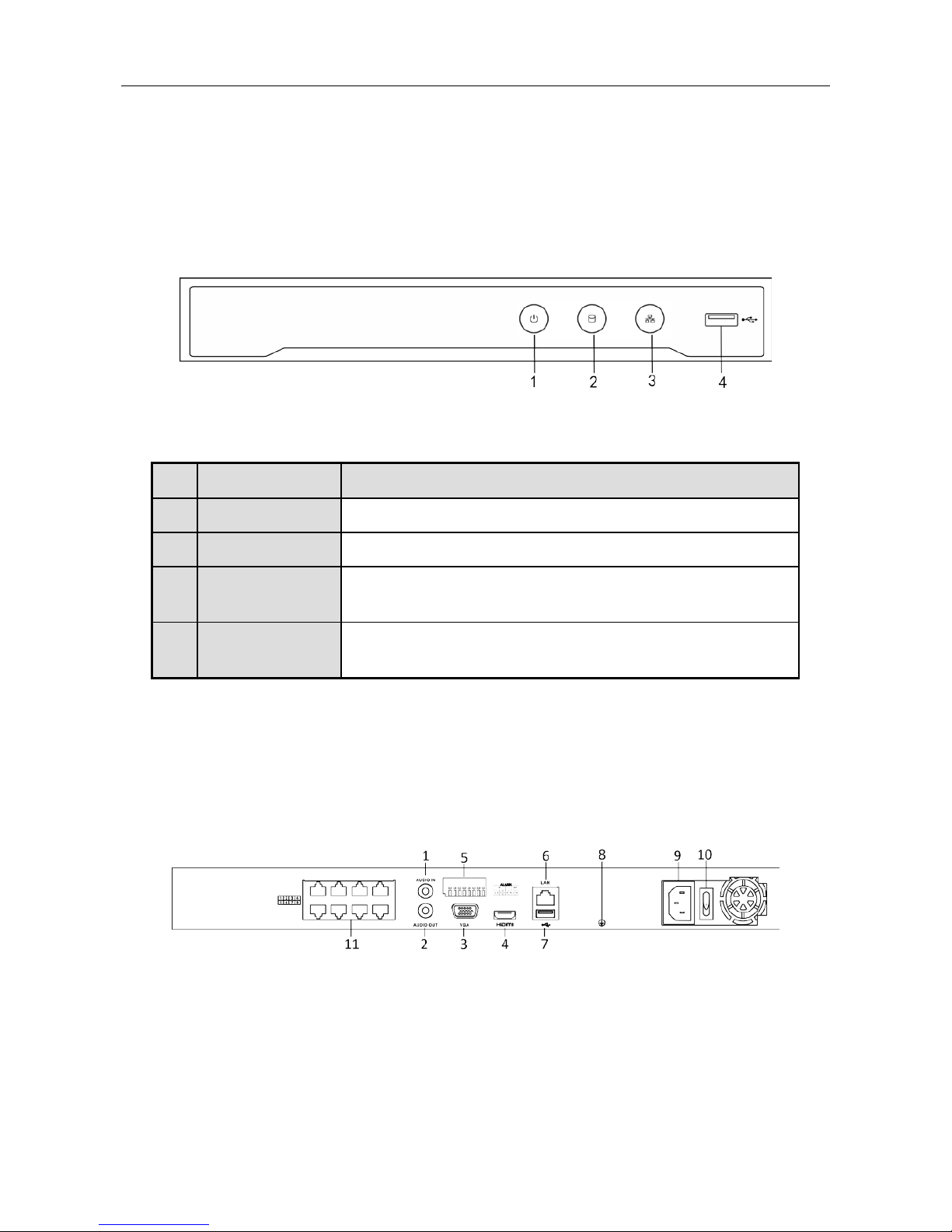
1.1.1 MVINVR-08POE04MP-E
Figure 1-1 MVINVR-08POE04MP-E
Table 1-1 Panel Description
1.2 Rear Panel
1.2.1 MVINVR-08POE04MP-E
MVINVR-08POE04MP-E
Figure 1-2 MVINVR-08POE04MP-E
No. Name Connections
1 POWER Turns green when NVR is powered up.
2 HDD Flickers red when data is being read from or written to HDD.
3 Tx/Rx
Flicker
s blue when network connection is functioning
properly.
4 USB Interface
Universal Serial Bus (USB) port for additional devices such as
USB mouse and USB Hard Disk Drive (HDD).

Network Video Recorder Quick Start Guide
7
Figure 1-3 Panel Description
No. Name Description
1 Audio In RCA connector for audio input.
2 Audio Out RCA connector for audio output.
3 VGA Interface DB9 connector for VGA output. Display local
video output and menu.
4 HDMI Interface HDMI video output connector.
5 ALARM IN Connector for alarm input.
ALARM OUT Connector for alarm output.
6 LAN Network Interface
1 10/100/1000 Mbps self-adaptive Ethernet
interface
7 USB Interface
Universal Serial Bus (USB 3.0
) ports for
additional devices su
ch as USB mouse and
USB Hard Disk Drive (HDD).
8 Ground
Ground (needs to be connected when NVR
starts up).
9 Power Supply
12 VDC power supply for
MVINVR-08POE04MP-E , and 100 to 240 VAC
10 Power Switch Switch for turning on/off the device.
11
Network Interfaces with PoE
function
(supported by
MVINVR-08POE04MP-E-I2/P)
Network interfaces
for the cameras and to
provide power over Ethernet.

Network Video Recorder Quick Start Guide
8
Chapter 2 Installation and Connections
2.1 Installation
During installation of the NVR:
Use brackets for rack mounting.
Ensure ample room for audio and video cables.
When routing cables, ensure that the bend radius of the cables are no less than five times than
its diameter.
Connect the alarm cable.
Allow at least 2cm (≈0.75-inch) of space between racks mounted devices.
Ensure the NVR is grounded.
Environmental temperature should be within the range of -10 to +55º C (+14 to +131º F).
Environmental humidity should be within the range of 10% to 90%.
2.2 Hard Disk Installation
Before you start:
Disconnect the power from the NVR before installing a hard disk drive (HDD). A factory
recommended HDD should be used for this installation.
Tools Required: Screwdriver.
2.2.1 MVINVR-08POE04MP-E
Purpose:
The following section introduces the HDD installation for the MVINVR-08POE04MP-E and
MVINVR-08POE04MP-E series NVR. Take the example of MVINVR-08POE04MP-E series to describe
installation steps.
Step 1 Fasten the hard disk mounting handle to the hard disk with screws.
Figure 2-1 Fasten Hard Disk
Step 2 Insert the key and turn in clockwise direction to open the panel lock.
 Loading...