

Page 1
1 00P5DG090DSEB1
ERIS3000 Series DVR
Setup Guide
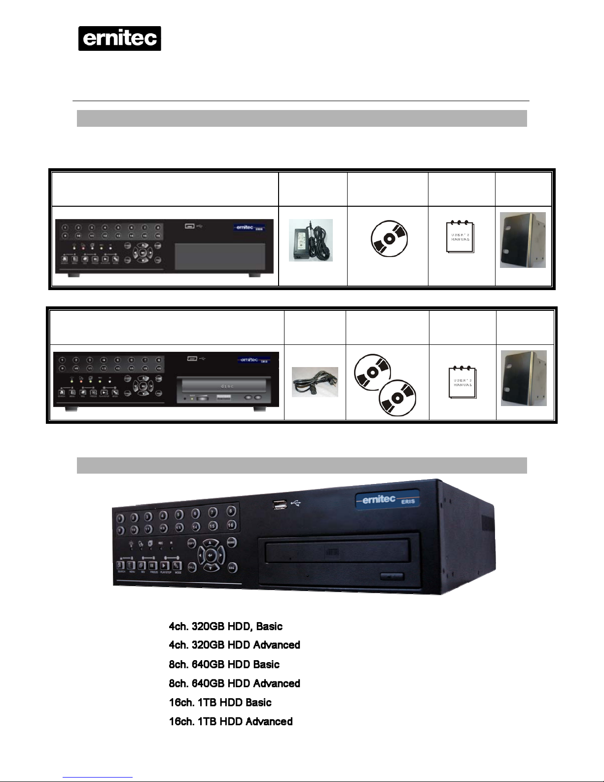
Package Content
Inspect the packaging carton. Make sure your ERIS 3000 Series DVR is properly delivered.
Remove all items from the box and make sure the box contains the following items.
ERIS 3000 BASIC
Power Adapter Software CD-CMS
User Guides PDF
User’s manual
Rack mount
ears
ERIS 3000 ADVANCED
Power Cord
Software CD-CMS
User Guides PDF
Blank CD-RW
User’s manual
Rack mount
ears
Different models
Page 2
ERIS3000
2
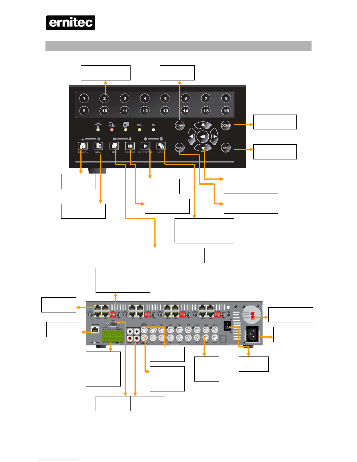
Function Keys on the Front Panel 16 Chanel
Numeric buttons
Dome Control
Escape
Direction keys and
zoom/Enter
Back-up
Call Monitor setup.
Split screen mode on
main monitor
Play/Stop
Pause/Freeze
Sequence setup
Menu/Setup
Search
Alarm In
Rs485
Alarm Out
VGA Out Audio Out
Main out
Composite
Call Mon
LAN
UTP
Select UTP (on) or
Video(off) Default
110/230 VAC
MAINS
On/Off
Video
input
Page 3

ERIS3000
3
Connector Description
LAN 10/100M
(RJ-45)
The DVR is capable of networking and it allows the videos to be viewed over the
LAN network or the Internet by using the Internet Explorer.
Audio In / Out
Audio In RCA connecto rs connect an audio source device to the unit.
Audio Out RCA connectors connect an audio output device to the unit.
Main Monitor
(BNC/VGA)
BNC and VGA output con nectors are to be connected to the main monitor.
Call Monitor
(BNC)
The call monitor is used to display full screen video of all installed cameras in
sequence. The BNC Call Monitor connector allows the user to connect the DVR
to a call monitor.
Video System
Switch
This switch is used to set the unit to PAL or NTSC.
Alarm I/O &
RS-485
The unit provides alarm I/O and RS-485 ports that offer users the flexibility
required to connect the unit to other devices.
BNC Video Input
A group of BNC connectors are provided for video input streams from installed
cameras.
Power Jack
ERIS BASIC Only
The DVR has an AC power connection jack. Please connect the power supply
cord and adapter that ships with the unit.
UTP Input
This offers additional connectivity using the Unshielded Twisted Pair wiring. UTP
cable is one of the most common medium in telecommunication industry.
Page 4
ERIS3000
4
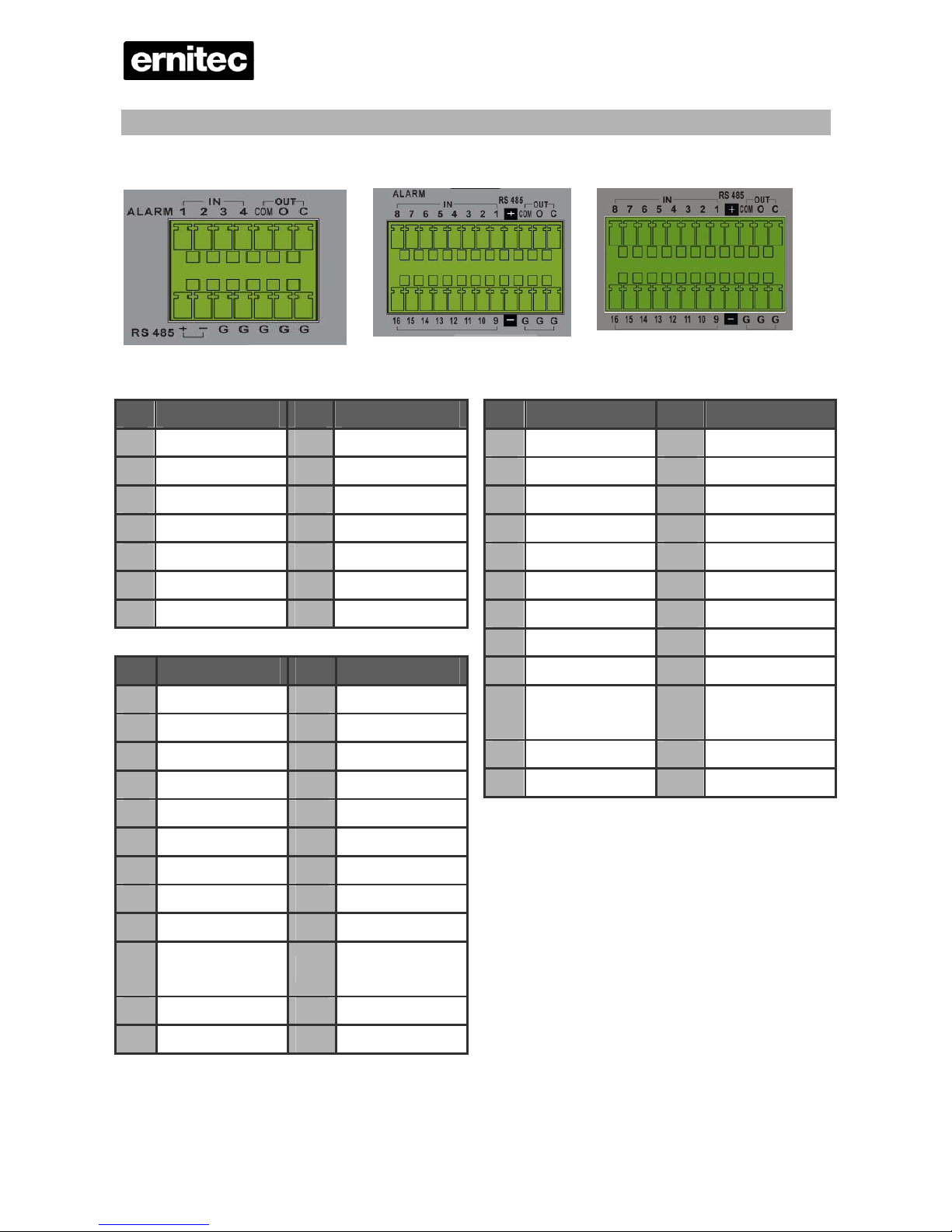
I/O connector Alarm, Rs485
4ch-Model 8 ch- model 16 ch- Model
4 Ch model 8 Ch model
Pin Definition Pin Definition
1 Alarm In 1 8 RS485 D+
2 Alarm In 2 9 RS485 D3 Alarm In 3 10 Ground
4 Alarm In 4 11 Ground
5 Common Node 12 Ground
6 Normal Open 13 Ground
7 Normal Close 14 Ground
Pin Definition Pin Definition
1 Alarm In 8 13 Alarm In 16
2 Alarm In 7 14 Alarm In 15
3 Alarm In 6 15 Alarm In 14
4 Alarm In 5 16 Alarm In 13
5 Alarm In 4 17 Alarm In 12
6 Alarm In 3 18 Alarm In 11
7 Alarm In 2 19 Alarm In 10
8 Alarm In 1 20 Alarm In 9
9 RS485 D+ 21 RS485 D-
10
Common
Node
22 Ground
11 Normal Open 23 Ground
12 Normal Close 24 Ground
16 Ch model
Pin Definition Pin Definition
1 Alarm In 8 13 Alarm In 16
2 Alarm In 7 14 Alarm In 15
3 Alarm In 6 15 Alarm In 14
4 Alarm In 5 16 Alarm In 13
5 Alarm In 4 17 Alarm In 12
6 Alarm In 3 18 Alarm In 11
7 Alarm In 2 19 Alarm In 10
8 Alarm In 1 20 Alarm In 9
9 RS485 D+ 21 RS485 D-
10
Common
Node
22 Ground
11 Normal Open 23 Ground
12 Normal Close 24 Ground
Page 5
ERIS3000
5
Basic Setup
Follow the description to set up the configuration of date/time, recording, and viewing mode of the
DVR. All configurations can be set via either the DVR or via web browser interface.
Enter OSD Setup menu:
• Press MENU to enter the OSD main menu.
• Enter password using Channel keys. The default passwords are as below.
Administrator Password User Password
1 2 3 4 4 3 2 1
• It is strongly suggested to change the passwords to prevent unauthorized access.
Date / Time Setting:
The user can choose to either enter the Date/Time manually or use the Time Sync function to sync
the time with the time server periodically.
To setup the Date/Time manually>>
• Select <Date/Time> in System Setup menu to enter the Date/Time menu.
• Select the date and time using LEFT/RIGHT keys; then adjust the value using UP/DOWN keys.
• The new date and time settings take effect after the changes are confirmed.
To setup the Date/Time using the Time Sync function>>
• Select <Date/Time> in System Setup menu to enter the Date/Time menu.
• Select <Time Zone> to enter the time zone. To find out your local time zone, please visit
wwp.greenwichmeantime.com
• After entering the time zone, the <Network Time Protocol Setup> option will appear. Select
the <Network Time Protocol Setup> to set the time server.
• The default time server is time.nist.gov
, but the user can change it to other time servers when
desired. A list of IP addresses of the time servers is listed below.
129.6.15.28 129.6.15.29 132.163.4.101
132.163.4.102 132.163.4.103 128.138.140.44
192.43.244.18 131.107.1.10 69.25.96.13
206.246.118.250 208.184.49.9 64.125.78.85
207.200.81.113 64.236.96.53 68.216.79.113
• After the time server is set, select <Manually Time Sync> to sync the time.
• The time sync can also be updated periodically. Select <Automatically Time Sync>, and the
time will be automatically synced once an hour.
NOTE: The <Time Zone> must be set to your local time zone or the <Network Time
Page 6

ERIS3000
6
Protocol Setup> will not be accessible.
Page 7

ERIS3000
7
To Define Recording Settings:
• Select <Record Setup> from the OSD main menu.
• Select <ezRecord> as Preset Configuration option, and select wanted number of recording
day; other setting will be automatic arranged by the unit.
• Consider your own needs and select a Preset Configuration setting from <Best Quality>,
<Standard>, and <Extended Record>. Detailed information refers to ERIS series DVR User’s
Manual, Preset Record Configuration.
• Adjust the Recording schedule, Pre-alarm, Circular and Audio parameters.
• When the settings are complete, press ENTER to confirm and save the settings; or ESC to
abort.
To Select Viewing Mode:
• Press MODE button repeatedly to select the desired display mode. The available viewing
modes are full-screen, 2×2, 3x3, and 4×4 split-window.
Network Setup
Using LAN / Cable Modem:
Configure the LAN setup when you plan to use a LAN, WAN, or Internet connection without a d ialup
modem. It requires an Ethernet connection to a network. The default ID of your ERIS DVR series
must be changed to avoid network conflicts.
• From Main menu, select <System Setup> Æ <Network Setup>, set the <LAN Select> item to
<LAN> or <PPPoE> according to your network application, and enter <LAN Setup>.
• For DHCP user, set the DHCP to <ON>. The IP address, Netmask, Gateway and DNS settings
are retrieved from network servers. DHCP is dynamic that the settings change from time to time.
• For Non-DHCP user, set the DHCP to <OFF>. You must enter an IP address, Netmask,
Gateway and DNS settings. Please obtain the information from your network service provider.
• To change the IP address, Netmask, Gateway and DNS value, press UP/DOWN keys to move
the cursor to the item. Use LEFT/RIGHT keys to access each section of the value and press
ENTER, then change the value using UP/DOWN keys.
• PPPoE users must set the <PPPoE Account>, <PPPoE Password> and <PPPoE Max Idle>
as well.
• When the settings are complete, press ENTER to confirm and save the settings; or ESC to
abort.
Page 8

ERIS3000
8
Dome Camera Connection
Dome Camera Connection & Settings:
• See section Connecting Your DVR
for RS-485 port pin definition.
• Refer to the following figure. Connect the R+, R- terminals on the dome camera to the D+, Dterminals on the RS-485 port by RS-485 cable respectively.
• To set up dome camera’s protocol and ID, press MENU to access the Main menu, and select
<Camera Setup>. The available protocols include <DynaColor>, <Pelco D>, <Pelco P>,
<AD422>, <Fastrax 2>, <JVC>, <Panasonic_C>, <Panasonic_N> and <None> (default).
Note that ID number must match the ID address defined by the dome camera.
• To configure the RS-485 parameters, select <System Setup> from OSD main menu, and then
select <RS485 Setup>. The default DynaGuard™ 090 series DVR RS-485 settings are 9600
Baud, 8 Data Bits, 1 Stop Bit and No Parity.
Dome Camera Control Button:
1. = Preset call and save
2. = Hint screen On/off
Focus/Iris
AUTO
SEARCH = Zoom Out, MENU = Zoom In
SEQ = Focus Near, FREEZE = Focus Far PLAY/STOP = Iris Close, MODE = Iris Open
Page 9

ERIS3000
9
Basic Playback Operation
Searching Recorded Video by Time:
• Press SEARCH button to enter the Search menu; the From Time and End Time of the available
video is listed on top of the screen. The value is unchangeable.
• Use Direction buttons to move the cursor for setting the Start Time; adjusting the date and time
values by UP/DOWN keys. Press ENTER to confirm or ESC to abort.
• Move the cursor to <Begin Playback> and press ENTER to start playing back the selected
video. Either press PLAY/STOP again or ESC to return to live video.
NOTE: If there is no available recorded video that matches your specified time and date, the
unit starts to playback from the next available video.
Searching Recorded Video by Event:
• Press SEARCH button to enter the Search menu.
• To search event video that was recorded on a specific camera, use LEFT/RIGHT keys to move
the cursor and press ENTER to select or de-select a channel.
• Move the cursor to <Event List> and press ENTER to list the event video of the selected
channels.
• The list displays each event by date, time, triggered camera and alarm type. The latest recorded
event video will be listed on the top. To exit the event list, press ESC.
• Use UP/DOWN keys to scroll through the Event List. Press ENTER to play back the selected
event record.
NOTE: The event list displays only the first 1024 events; as some events are deleted,
others are displayed.
Playback Controls:
Button Description
LEFT
The button is for rewinding the recorded video while playing back. Press the button
repeatedly to increase the speed of reverse playback by 1×, 2×, 4×, 8×, 16×, or
32×.
RIGHT
The button is used to play the recorded video fast forward. Press the button
repeatedly to increase the speed of forward playback by 1×, 2×, 4×, 8×, 16×, or
32×.
FREEZE
Press FREEZE to pause the playback video. When the recorded video is paused,
press LEFT / RIGHT to resume playback video single step reverse / forward
respectively. Press FREEZE again to continue playing back video.
Play/Stop
Press to stop playing back video and return to live mode.
Page 10

ERIS3000
10
Software upgrade
You can get the latest Software on our web support page.
http://support.ernitec.dk/customers
Login: ErnitecGuest
Password: 3333
Select DVR
Select ERIS
Select Software
Download ZIP file
In the Zip file there is a file Readme.TXT. Read this and follow the instructions given in it.
Be Very carefully if the file is not unzipped correct the ERIS can not find the update.
Software upgrade via USB:
• Press MENU button to enter the menu.
• Enter Admin Password, Default 1,2,3,4. Press ENTER
• Select SYSTEM SETUP and press ENTER
• Select VERSION and press ENTER
• Select SOFTWARE UPGRADE VIA LOCAL DEVICE Press ENTER
• Insert the USB Key with the upgrade on. Press ENTER to select UPGRADE or ESC to
CANCEL.
ERIS will now search for an update on the USB key,
Remove the USB Stick and Restart ERIS when the update is finished.
ERIS is now ready with the latest software.
Page 11

ERIS3000
11
Using Remote Software
Setup Requirements:
• Make sure the PC is connected to the Internet.
• Obtain IP address of your ERIS 3000 series DVR. To check the DVR’s IP address, press MENU
key on the unit and select <System Setup> Æ <Network Setup> Æ <LAN Setup> Æ <IP> to
check the IP.
Changing Internet Setting:
• Start the IE; select <Tools> from the main menu of the browser, then <Internet Options> and
then click the <Security> tab.
• Select <Trusted sites> and click <Sites> to specify its security setting.
• Uncheck “Require server verification (https:) for all sites in this zone”. Type the IP address of the
unit in field and click <Add> to add this website to the zone.
• In the Security Level area, click <Custom Level>. Under <All ActiveX controls and plug-ins>,
set all items to <Enable> or <Prompt>.
• Click <OK> to accept the settings and close the <Security Settings> screen.
Page 12

ERIS3000
12
Web interface
Open your Browser, type in the IP address of your ERIS.
The Login window opens. Default User name is <admin> Default Password is <1234>
Make sure you change it, and make sure you store the new password in a safe place!
The WEB interface of ERIS starts
Page 13

ERIS3000
13
On your left hand, you can
choose Camera.
There are different symbols
1. Camera.
2. Speed dome,
Select a Dome camera, then the
Dome control appears on the left
Hand
4, 9 and 16
video windows
Down load
player by
selecting this
symbol
To enter the menu in a Speed Dome PELCO protocol Call preset 95.
The menu appears on the screen.
Move around with the direction keys. To enter a menu pres FOCUS +
Dome ID can be change by selecting
Preset can be set by selecting The current position will be stored.
Call a preset by selecting
Adjust the speed of the dome
Page 14

ERIS3000
14
To Playback Remote Video:
• Click <Play> on the main window toolbar, and then <Remote Playback> tab.
• The <From> and <To> on top of the screen display the date and time from which recorded
video is available for playback.
• Choose <Playback> in <Select> field for playback recorded video.
• Select the date and time of the segment to play back from the <Start> field. You can change the
date and time either by typing desired numbers directly or using the arrow buttons.
• Click <OK> to start the playback, or click <Close> to abort.
To Playback Local *.drv File:
• Click <Play> on the main window toolbar, and then <Local Playback> tab.
• Click <Open> and the file selection screen is displayed. Select the *.drv video file to playback
and click <OK>.
• Click <OK> to start the playback, or click <Cancel> to abort.
• View the video playback using the Playback controls.
• To end the playback, click <Live> to return to live video.
Page 15

ERIS3000
15
Snapshot will be
saved on the desktop
Select 4:3 on the
video window
Check the size of
the hard drive.
In the menu you can
Remote Configure
ERIS
To Playback Event Video
• Click SEARCH on the main window toolbar. The Event List appears.
• Scroll through the Event List and highlight the interested events.
• Double-click on the desired event to view the event video.
• <M> Motion <A > Alarm
Page 16

ERIS3000
16
Remote Controller
A remote control is provided for the DVR unit. The function keys on the remote control are
listed as below figure:
Page 17

ERIS3000
17
Specifications 4ch Model 8ch Model 16ch Model
Video ERIS BASIC / ERIS ADVANCED
Input
BNCx4 / UTPx4,
1.0Vp-p, 75 ohm
BNCx8 / UTPx8,
1.0Vp-p, 75 ohm
BNCx16 / UTPx8,
1.0Vp-p, 75 ohm
Video St andard
NTSC/PAL switch selectable
Video Operation
Triplex (Live / Playback, Record, and Network)
Main Monitor
BNCx1, 1.0Vp-p, 75 ohm
Call Monitor
- BNCx1, 1.0Vp-p, 75 ohm
Outputs
VGA (Optional)
800x600, 1024x768, 1280x1024 pixels @ 60Hz
Picture Refresh Rate
NTSC: 120PPS; PAL: 100PPS (4, 8 and 16CH)
Digital Zoom
2x2
Camera Installation
Plug & Play
Audio
Input
RCAx1, Line-In
Output
RCAx1, Line-Out
Recording Mode
Always Real-time Record, Synchronized with Video
Compression Method
ADPCM, G.726
Data Rate
4 KB / s, per channel
Operation
VCR mode
Playback
Only for Video Original Speed
Recording
Compression Method
MPEG-4 Advanced Simple Profile
Recording Mode
Schedule, Alarm, Motion Detection
Pre-alarm
Yes
Recording Resolution &
Rate
NTSC: 30PPS@720x480 pixels; PAL: 25PPS@720x576 pixels
NTSC: 60PPS@720x240 pixels; PAL: 50PPS@720x288 pixels
NTSC: 120PPS@360x240 pixels; PAL: 100PPS@360x288 pixels
Recording Mode
Best Quality, Standard, easyRecord, Extended Record, DSL
Image Size
8K to 20K Byte/Picture
Storage Mode
Linear/Circular
Playback
Playback
Play, Stop, Pause, Rewind, Forward, Search
Playback Speed
Adjustment
Yes (1x, 2x, …32x)
Retrieve
Date / Time, Event
Page 18

ERIS3000
18
Storage
Built-in HDD
Up to 2 built-in SATA HDDs
Export
USB
USB 2.0 CD / RW (Optional)
USB Thumb Drive
Support
Alarm
Alarm Input
X4, Terminal X8, Terminal X16, Terminal
Alarm Detection
N.C./N.O., Programmable
Alarm output
N.C/N.O, programmable 3.0 A / 30 VDC or 3.0 A / 125 VAC
Auditory Alert
Built-in Buzzer
Motion Detection
16x12
Video Loss Detection
Programmable
External I/O Board
(Optional)
Terminal Block (2 x 6) T erminal Block (4 x 6)
Communication
Communication Protocol
RS-485 DSCP
Remote Control Software
CMS, Remote Software/Browser
Network Connectivity
Ethernet RJ-45 connector, 10/100Mb ps, supports DHCP
LAN Remote Control
IE Browser, Windows AP
Dome Camera Control
Protocol
DynaColor, Pelco P, Pelco D, AD422, Fatrax 2, Panasonic
Remote Operation
Monitor, Playback, Recording, System Setup, Dome Camera Control
On-Screen Display
Search
Based on Time or Event
Play/Pause/REW/FF
Control Playback Direction & Speed
Password Control
2 Level, Administrator / User
General
Unit Dimension (WxHxD)
440 x 55 x 413 mm (17.3 x 2.2 x 16.3 inches)
Unit Weight
4.9 kg (10.8 lbs)
Operation Temperature
0°C - 40°C (32°F - 104°F)
Relative Humidity
5% - 85% Non-condensing
Power Consumption &
Input
ERIS BASIC 4/8/16 19W/30W/34W Ext. Adapter, AC 100 ~ 240V to DC12V
ERIS ADVANCED 4/8/16 50W/61W/65W 110-230V select able
Page 19

ERIS3000
19
Brand Model Name Model Number Size
Seagate
SV35 Series™ 7200.1 ST3500641AV 500G
SV35 Series™ 7200.1 ST3250824AV 250G
SV35 Series™ 7200.1 ST3160812AV 160G
SV35 Series™ 7200.2 ST3320620AV 320G
DB35 Series™ 7200.3 ST3320820ACE 320G
Barracuda® 7200.8
ST3400832A 400G
Barracuda®7200.8
ST3250823A 250G
Barracuda® 7200.9
ST3500841A 500G
Barracuda® 7200.9
ST3400633A 400G
Barracuda® 7200.9
ST3300622A 300G
Barracuda® 7200.9
ST3250824A 250G
Barracuda® 7200.9
ST3160812A 160G
Barracuda® 7200.10
ST3750640A 750G
Barracuda® 7200.10
ST3320620A 320G
Barracuda® 7200.10
ST3250620A 250G
Western Digital
WD Caviar® SE
WD3200JB 320G
WD Caviar® SE
WD2500JB 250G
WD Caviar®
WD1600BB 160G
WD Caviar®
WD1200BB 120G
HITACHI
Deskstar® 7K400
HDS724040KLAT80 400G
Deskstar® 7K160
HDS721616PLAT80 160G
CinemaStar™ 7K500 HCS725032VLAT80 320G
CinemaStar™ 7K500 HCS725025VLAT80 250G
CinemaStar™ 7K160 HCS721616PLAT80 160G
 Loading...