

Page 1
Installation Manual
Ernitec Eagle PIR-045 & 045H
Medium-Range Curtain
Detectors for Perimeter Protection Outdoors
Version 2.0 and higher
Standard Models
• PIR-045 Standard
Nominal Range 50 m (165 feet)
• PIR-045H High Performance
Nominal Range 60 m (200 feet)
Highlights
• Gap-Free Coverage with Creep Zones
• 4 Meter (13 Feet) Mounting Height
• Advanced Tamper Detection
• Low Power Consumption – Ideal for Wireless and
Solar Applications
• Wide Power Supply Range
• Heater & Heavy Duty Front Window (H version only)
• Integrated Bracket for Wall Mounting
• Remote Configuration and Alarm Management
Page 2

www.ernitec.com
Page 3

Table of Contents
Page
Standard Models .......................................................................................................................................... 1
Highlights..................................................................................................................................................... 1
1 Introduction...........................................................................................................................................4
2 Mounting and Installation....................................................................................................................4
3 Connecting the PIR...............................................................................................................................4
4 Field of View..........................................................................................................................................5
5 Alignment ..............................................................................................................................................5
6 Sensitivity Settings ...............................................................................................................................6
7 Adaptive Threshold Discrimination (ATD) .........................................................................................6
8 Anti Vandal Function............................................................................................................................7
9 LED.........................................................................................................................................................7
10 Alarm Management ...............................................................................................................................7
11 Alarm Time ............................................................................................................................................7
12 Internal Temperature Compensation.................................................................................................7
13 Internal Heater ( H version only)..........................................................................................................8
14 External Sensitivity Adjustment via RS 485 Data Bus.....................................................................8
15 Signal Processing .................................................................................................................................8
16 Accessories...........................................................................................................................................9
16.1 Interface Module and Installation Software ...........................................................................................9
16.2 Pole Mount Hardware .........................................................................................................................9
19 Maintenance........................................................................................................................................10
20 General Comment on the PIR............................................................................................................10
21 Appendix Electronic Board and Terminal Block ............................................................................11
21.1 Terminal Block .................................................................................................................................11
21.2 Dip Switches....................................................................................................................................11
22 Appendix Two Way Communication RS 485...................................................................................12
22.1 Introduction .....................................................................................................................................12
23 Appendix Installation Software.........................................................................................................13
23.1 Introduction .....................................................................................................................................13
23.1.1 Application of the Installation Software...............................................................................................13
23.1.2 Software Installation .........................................................................................................................13
24 Appendix Specifications....................................................................................................................14
24.1 Mechanical Dimensions ....................................................................................................................15
Page 4

Installation and Maintenance
1 Introduction
The P IR is a highly sensitive Passive Infrared Detector designed for detection outdoors with a wide angle,
volumetric differential field of view. It incorporates microprocessor-controlled signal processing including signal
shape analysis, adaptive threshold level by feedback of environmental effects, temperature compensation and
rejection of disturbance signals.
Sensitivity adjustments are done with DIP -Switches for each individual unit in function of the required detection
range in order to adapt to the specific needs of an installation.
In addition to the hardware settings, adjustments can be made in a two way communication mode and signals
displayed on a PC screen by using the optional installation software and RS 485 communication interface module.
2 Mounting and Installation
The mounting structure should be stiff enough and resist to significant deflections in windy conditions. Movement of
the PIR caused by vibrations or other movements will result in swings of the field of view covered by the PIR and
could cause disturbance signals. These unwanted signals may lead to an increase of the alarm threshold level
which reduces the detection probability or in certain cases can lead to unwanted alarms.
The stainless steel bracket is ideally suited for wall mounting (using screws). For pole mounting the original
accessory is available (pole mounting bracket with two strap bands for poles up to 4 – 16 cm in diameter). For
further information please refer to 16.2.
• It is very important that the cover of the PIR is securely tightened. It must be tightened with the two screws to
the point where it cannot be closed further with reasonable force. There will then be hardly any gap between
the cover and the bottom part of the housing (considerably less than 1 mm).
The detectors are fitted with two cable entry assemblies of M16. The nut on the cable entry assembly should be
tightened to clamp the cable in place with reasonable force. If the cable diameter is too small to be held properly,
insulation tape should be wound around the cable to increase the outside diameter to a suitable size.
3 Connecting the PIR
For the definition of the electronic board and terminal block see appendix 19.1.
Alarm Signalling
There are three types of alarm signalling from the P IR:
• one SPST potential-free relay contact
• one open collector transistor output
• an RS 485 two way communication link (see appendix 20 for details)
With the detector in factory setting the relay contact opens and the transistor switches to low resistance on alarm.
Output logic and function can be changed using the installation software.
During turn-on time the relay output is in alarm state!
Cover Switch
To detect attempts to open the detector, a switch is fitted for the cover. Its contact opens when the cover is opened.
Page 5
4 Field of View
The P IR has a wide angle, volumetric field of view with differential detection areas. The nominal ranges refer to the
table below.
Definition PIR-018 PIR018H
Nominal Range 50 m (165 feet) 60 m (200 feet)
Width at Nom. Range 3.3 m (11 feet) 3.9 m (13 feet)
5 Alignment
The detection range of a PIR detector is not limited but a function of size, speed and temperature contrast of a
target against its background. The PIR should be aligned so that a natural or artificial background at the end of the
range terminates the field of view.
Vertical alignment is optimal when the upper edge of the field of view is at 1.5 to 2.5 m above ground at the end of
the required detection range provided that the field of view is properly terminated.
Alignment can be done visually by looking along the grove on the top of the detector. This line of sight cor responds
to the upper edge of the detection pattern.
Where the detection range has to be limited, a terminating screen can be used to avoid detection of targets beyond
the wanted range.
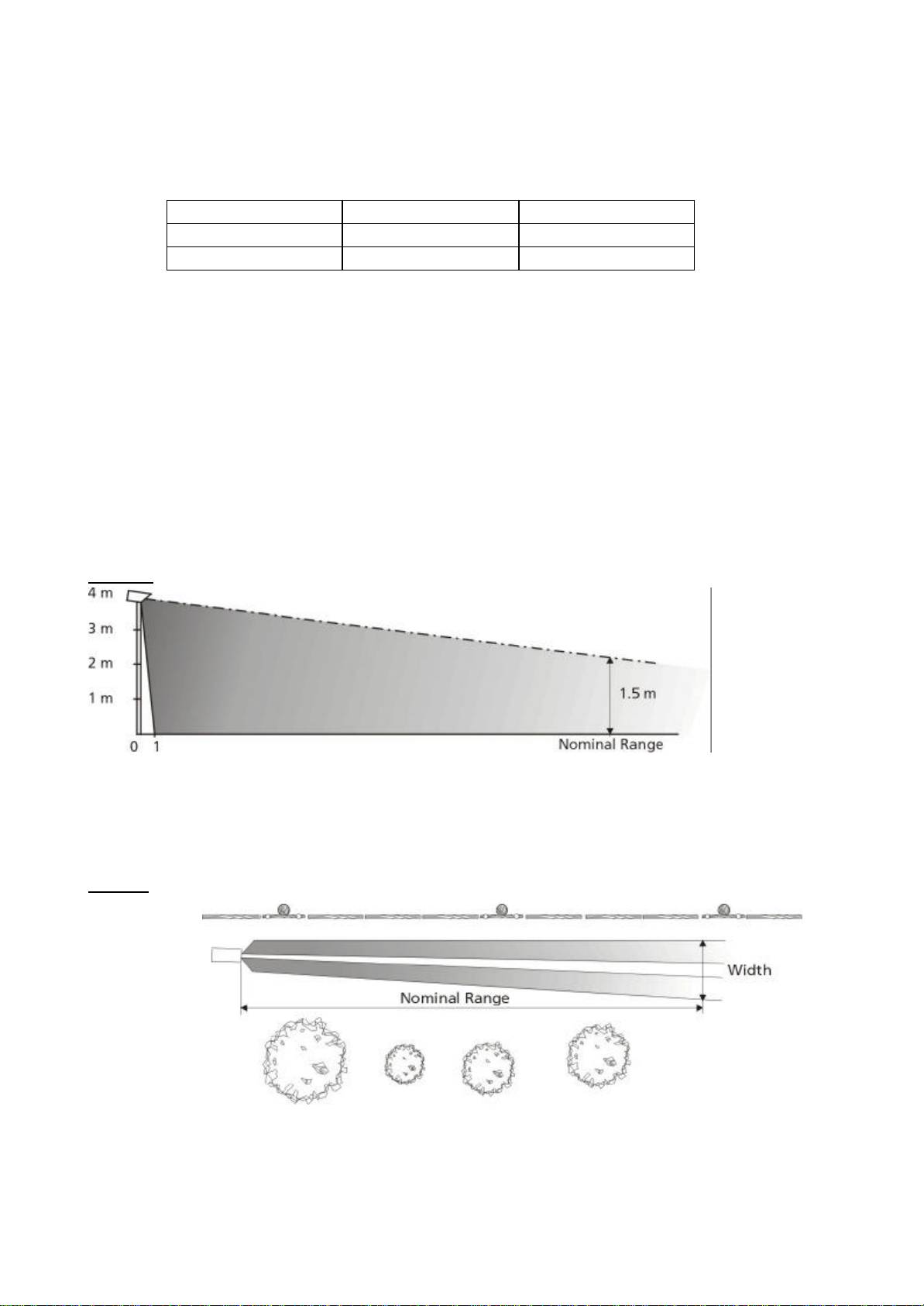
Typical vertical alignment for a required detection up to nominal range.
The PIR should be aligned vertically so that at least the lower half of a person standing upright at the maximum
required range will be within the field of view (see Fig. 1 below).
Side view
Fig. 1
Typical horizontal alignment
Horizontal alignment should be done in a way to avoid unwanted signals being generated by tar gets (branches,
bushes, fences) likely to be moved by wind (see Fig. 2 below). Movement within the field of view will reduce the
sensitivity of the PIR by increasing the alarm threshold level and may lead to un wanted alarms.
Top view
Fig. 2
Note: The width of the zone at ground level near the detector is in the order of 1.6 m (5.5 ft) edge to
edge when the detector is mounted in 4 m (13 ft) height. This means that special care has to be
taken when mounting a detector onto a wall and aiming along the wall in order not to pick up
disturbances caused by air turbulences along the wall.
Page 6

6 Sensitivity Settings
The various settings of the PIR are made by means of multiple DIP - Switches on the printed circuit board.
The DIP – Switches 1 and 2 are for sensitivity setting depending on the required detection performance. If the
maximum required range is less than the nominal range of the detector, it is recommended to reduce the overall
sensitivity to reduce nuisance alarms.
Switch
1 and 2
off – off 40 %
off – on 75 %
on – off 100 % Factory Setting
on – on Software Settings *) 20 … 140 %
*) With the DIP - Switches 1 and 2 both set to „on“, the overall sensitivity is 100% factory setting but can be
changed with the installation software.
If the sensitivity is adjusted with the installation software, the programmed value will remain active also following
a power off.
Operation of the PIR with overall sensitivity set to more than 100% is not recommended in outdoor applications
as the nuisance alarm rate could increase signi ficantly.
Overall
Sensitivity
7 Adaptive Threshold Discrimination (ATD)
The background noise is constantly averaged and used to adjust the threshold levels for the alarm. This special
feature is reducing the probability of nuisance alarms caused by wind, moving vegetation or objects that have a
thermal contrast although usually weaker than a person.
Each signal exceeding a certain minimum value will activate the ATD and increase the threshold levels de pending
on its strength. The time constants for increase and decrease are chosen in a way to adapt to gradual changes.
Signals generated by a person moving within the specified speed range, however, are strong enough for detection.
Repeated movement of any kind within the field of view is therefore activating the ATD, reducing the overall
sensitivity. This has to be noted particularly when walk testing the following installation.
The DIP – Switch 3 is used to activate or deactivate the ATD (Adaptive Threshold Discrimination).
Switch 3 ATD
off off *)
on on Factory Setting
*) Operation of the PIR in this mode is possible but not recommended in outdoor applications as the nuisance
alarm rate could increase significantly as a result of turbulences.
• When walk testing the unit, the threshold level will increase as a result of the signal generated by the target
and decrease exponentially in time after the event. To make sure that original sensitivity is reached, wait at
least for 3 minutes between each crossing or disable the ATD function by setting DIP - Switch 3 to „off“.
If the Installation software is used for monitored walk tests and the DIP – Switches 1 and 2 are set to software
settings (on – on), the threshold level can be kept to its nominal value by changing the configuration of the ATD to
„off“ for this test.
The DIP – Sw itch 4 & 5 has no function in these detector models.
Page 7

8 Anti Vandal Function
The PIR is equipped with a sophisticated protection against vandalism. These detectors can sense certain
changes of their alignment from the original position as set during the installation. A change of the detector’s
alignment generates a permanent alarm until the detector’s alignment is back in its original position or until the
position has purposely been reset.
When using the alarm management with RS 485 communication a vandal alarm will be identified separately.
After the turn-on time of typ. 60 seconds from power on, the detector determines and stores its alignment position
(only with detector cover closed).
After opening and closing the cover with the unit powered on, the det ector determines its alignment position and
stores the position value after 5 minutes again without having the detector in permanent alarm state. During this
time the anti vandal sensor can be reset with a power off-on only.
During normal operation resetting the anti vandal sensor after the detector’s position has been changed, can be
done either remotely with the setup program (takes app. 10 seconds) or a power off-on (60 seconds).
Hardware Mode:
When operating the detector in the HW mode, the anti vandal function is activated by setting DIP – Switch 6 to „on“.
Switch 6 Anti Vandal Function
off off
on on Factory Setting
Software Mode:
Operating the detector in the SW mode, the anti vandal function is activated by means of setting of the
corresponding parameter in the settings of the setup programs to „on“.
9 LED
The electronic board is fitted with a dual LED having a red and green colour side. This can be monitored during
installation while the cover is open.
§ The red LED indicates whether the detector is in alarm state or not
§ The green LED flashing at 2 Hz frequency indicates the detector ready state.
During the turn-on time the red LED is on.
10 Alarm Management
The PIR features an alarm management function over RS 485 communication. All the detectors connected to the
same data bus provide all the information relevant to an alarm in a defined protocol frame. For further information
please contact the manufacturer.
11 Alarm Time
Alarm time per event is determined by the duration of the detected event and depends on the shape and amplitude
of the alarm signal. Individual alarm pulses have a minimum time of app. 2.5 s.
12 Internal Temperature Compensation
The P IR is detecting radiation differences of a target against its background. In the course of the day and year the
contrast of a person will vary considerably and affect the signal strength. To compensate for this contrast variation,
the PIR has internal temperature compensation with maximum sensitivity at app. 30°C (where the contrast of a
human target is weakest) and gradual reduction at higher and lower temperatures.
• When installing a unit the internal temperature may take up to 30 minutes or more to stabilise to the actual
external temperature. Sufficient time should be given to the PIR to reach the correct internal temperature and
sensitivity before performing walk tests.
During the initial period of operation it is strongly recommended that walk tests are repeated and signals monitored
under various weather conditions such as high and low temperatures, wind fog, snow, rain etc. to obtain
comparative data and information on the effects of environmental conditions on detection and nuisance alarm
probabilities for this particular site. Fine-tuning of the detector based on this data by changing the sensitivity
settings may optimise the performance.
Page 8

13 Internal Heater (H version only)
A regulated heater connected to the electronic board and powered by the supply voltage of the PIR prevents the
optical surfaces from fogging or frosting and maintains the internal temperature at optimal levels.
14 External Sensitivity Adjustment via RS 485 Data Bus
If the DIP - Switches 1 and 2 are both set to „on“, the detection performance can be adjusted via the RS 485 two
way communication port. Overall sensitivity of the PIR can be set to any value between 20 and 140 %.
The external sensitivity adjustment may also be used if overall sensitivity has to be changed at certain periods of
the day or year depending on the prevailing thermal contrasts. Field tests in the actual environment will determine
the optimum settings.
15 Signal Processing
The sophisticated signal processing ensures an optimum performance and reliability of the detector.
The background noise is sampled and averaged over a large number of cycles giving a noise dependent valu e for
the alarm threshold and to start the adaptive signal shape analysis whenever a certain amplitude value is
exceeded.
If the threshold has temporarily been increased by high background noise or repeated movements in the field of
view, the exponential decay of the threshold level to its original value will take app. 1… 2 minutes from the end of
the event.
Once the threshold level value has been exceeded, the microprocessor starts its signal shape analysis routine
where a number of interdependent parameters are calculated and analysed.
Only if a signal meets all the predetermined criteria an alarm will be generated.
Page 9

16 Accessories
16.1 Interface Module PIRIF-485/2 and Installation Software
The Installation Software is very useful for alignment and signal check du ring setting up and routine maintenance. It
will indicate the amplitudes generated by wanted as well as unwanted targets and help setting the gain control
correctly during walk tests and also show the magnitude of disturbance signals. The installation soft ware is to be
installed on a PC; an interface module is required to convert RS 232 to RS 485. The information for installation and
signal monitoring is displayed on the screen of the PC.
If more than one detector is connected to the same RS 485 communicat ion bus, each detector needs to have a
different identification number.
Please see the PIRIF-485/2 Installation and Setup Manual, for further details.
16.2 Pole Mount Hardware
Pole mounting bracket with two strap bands for poles up to 4 – 16 cm in diameter
Page 10

17 Maintenance
The detector has been designed to be virtually maintenance free but the following precautions are recom mended:
1) Visual inspection of the front window for accumulation of dirt on the outer surface or damage at intervals of
app. 6 mont hs. Clean the surface with a paper tissue and avoid rubbing dirt into the surface. Use the same
precautions as for a camera lens.
2) Walk tests for checking the detector alignment and sensitivity settings to ensure optimal performance and
reliability.
3) Inspection is recommended following extreme conditions such as snow storms, sand storms, hail etc. to
make sure that nothing has been damaged and the sensitivity is not re duced by accumulation of snow, sand or
dirt on the front window. Snow or dust in front of the window should be removed by hand or by using of a soft
instrument (e.g. a wooden stick).
18 General Comment on the Eagle PIR
• Despite the advanced design and state-of-the-art features of the PIR it is in the nature of a Passive Infrared
Detector that an absolute detection probability and freedom from nuisance alarms cannot be achieved, masking
of the PIR cannot be excluded.
• Detection is a function of thermal contrast, speed and size of a target crossing the field of view. Contrast
conditions can vary significantly in the course of the day and year.
• Detection depends also on the sensitivity settings, the exact aiming and the prevailing weather conditions as
well as the nature of the target and background.
• The detection pattern and frequency response of the PIR has been optimised for the detec tion of human size
targets crossing the field of view in an upright position at speeds in the range of 0.2 … 5.0 m/s.
• Detection of slow moving targets at long range may become uncertain under weak contrast conditions. It is
strongly recommended to limit the zone length to less than the nominal range when human targets moving at
the minimum specified speed need to be detected with high probability.
• Animals or crawling people may or may not be detected depending on their size, speed, contrast and distance
from the detector.
• It is therefore strongly recommended to combine the PIR with alarm verification such as CCTV or a second
system using other physical means of detection (e.g. VMD or active IR beams).
• Any liability for direct or indirect damage resulting from the use of the PIR as a detection de vice is explicitly
disclaimed.
• The information in this product manual is based on testing of samples taken at random from pro duction and
believed to be representative , and is subject to changes without notice.
Page 11

Sensitivity
Function Switches
Cover switch
Output (Transistor OC)
Test
4.7 kO
19 Appendix Electronic Board and Terminal Block
Top View
19.1 Terminal Block
8
7
100 mA
*
+ 6 V
50 mA
* Relay shown in energised (non-alarm) condition
6
Common
5
Normally closed*
4
3
Not used
2
- GND Supply voltage
1
+ 10.5 ... 30 V DC / 24 V AC
B
RS 485
A
(RJ12)
19.2 Dip Switches
SW1 SW2 Function
ON ON SW settings
ON OFF HW setting 100%
OFF ON HW setting 75%
OFF OFF HW setting 40%
SW Function
3 ATD
4 Pulse count
5 Test
6 Anti-vandal function
Page 12

120R
A B
20 Appendix Two Way Communication RS 485
20.1 Introduction
The PIR is equipped with a RS 485 interface for two -way communication between the detector and a PC or other
control device. This communication link is used for detector set -up and remote adjustments as well as for signal
monitoring.
It can either be used temporarily for installation or permanently wired for remote access to the detector from the
control room. RS 485 can accommodate up to 32 detectors on the same data bus with a maximum bus length of
1000 m – provided the detectors have all different ID’s and the data link is properly termi nated at both ends. There
is no terminating resistor built into the detector. The last detector on the bus, on the opposite side of the interface
module, also needs a terminating resistor of 120 Ω. This can be accomplished by adding a resistor between the
wires RS 485 A and RS 485 B.
Please see the PIRIF-485/2 Installation and Setup Manual, for further details.
Page 13

21 Appendix Installation Software
21.1 Introduction
The installation software is available as ac cessory for alignment, setting up and fault finding. It can be used for
remote programming and verification of all detectors connected to the same RS 485 data bus and is recommended
for verification of all installa tions in order to optimise the performanc e of the detectors. If more than one detector is
operated over the same communication link it is necessary that the detectors have different addresses (ID’s).
For operation with a standard PC a converter to RS 485 is required. The interface box is available as accessory.
21.1.1 Application of the Installation Software
The installation software is a most useful tool for remote programming and for checking the alignment of the
detectors. It greatly facilitates the optimisation of an installation to suit a particular site.
Independently of the position of DIP-Switches 1 and 2 (hardware or software settings) the program is capable to
display the actual parameter settings as well as the analog signals of the selected detector.
For remote programming purposes the DIP-Switches 1 and 2 have to be switched to on-on position (software
settings). Now all parameter settings can be altered with the software.
The software is particularly helpful in situations where a detector is operated under conditions near the
recommended operating limits of height, detection range and target speeds. The information supplied by the PC
display should be used to monitor the detection performance of the detector and make adjustments if required.
Depending on the site’s animal activity, vegetation moving in the wind and/or other sources of disturbance it is
possible that unwanted alarms occur. Monitoring and interpreting the information supplied by the installation
software will help finding the best solution either by adjusting the alignment and/or settings of the detector or by
removing disturbance sources from within the field of view.
Please see the PIRIF-485/2 Installation and Setup Manual, for further details.
Page 14

22 Appendix Specifications
Model PIR-045 PIR-045H
Optical
Nominal Range 50 m (1 65 ft) 60 m (200 ft)
Width @ Nominal Range 3.3 m (11 ft) 3.9 m (13 ft)
Mounting Height 2.5 … 4.0 m (8 … 13 ft)
Detection Speed 0.2 to 5 m/s (0.7 to 17 feet/s)
Sensor Pyroelectric, differential single channel
Spectral Response 8 – 14 µm, double filtering
Optics Segmented precision mirror
Front Window Plastic, IR transmissive Silicon wafer
Sensitivity Adjustment DIP switches and RS 485
Mechanical
Case Material Heavy duty plastic
Colour white
Weight app. 900 g (2.0 lbs), incl. mounting bracket
Cable Feeds 2 x M 16 with cable clamp
Outer Cable Diameter 4.5 … 10 mm (0.18 … 0.40 inch)
Electrical
Supply Voltage
Current Consumption
Alarm Relay Output SPST rated 30 V DC, max. 100 mA
Transistor Output
Cover Switch 30 V DC, 100 mA
Turn-on Time typ. 60 seconds from power on
Communication Bi-directional RS 485 @ 9600 baud
Test Socket
Wiring Terminal Block 0.34 mm2 … 1.5 mm2 (AWG 28 … 16)
Environmental
Operating Temperature
Humidity 95 % RH max.
Sealing IP 64 splash proof
typ. 18 mA @ 12 V DC
typ. 10 mA @ 24 V DC
(–4ºF … +140ºF)
10.5 … 30 V DC / 24 V AC (± 15%)
PIR-045 specs. + Heating
Power @ –40°C (F) max. 2 W
Open collector NPN, 30 V DC, max. 50 mA
ü ü
–20°C … +60°C
–40°C … +60°C
(–40ºF … +140ºF)
Page 15

22.1 Mechanical Dimensions
 Loading...