

Page 1

Digital Video Recorder
Series EDNS3000
16 camera system
Installation,
Programming,
& User Manual
Page 2

DigiOpG2 Digital Video Recorder Page 1
3040-00052
Page 3

DigiOpG2 Digital Video Recorder Page 2
3040-00052
WARNING
TO REDUCE FIRE OR SHOCK HAZARD, DO NOT EXPOSE
THE UNIT TO RAIN OR MOISTURE.
This installation should be made by a qualified service person and should
conform to all local codes.
Page 4

DigiOpG2 Digital Video Recorder Page 3
3040-00052
Cautions
Read Before System Operation
Follow these details to prevent material damage or personal injury.
Signs of Caution and Warning
Warning: This sign indicates that the user could be seriously wounded or expect property damage if not
used or installed properly.
Important Safeguards
Warning
1. Use the power cord, which is supplied or recommended by the supplier.
2. Do not dismantle or assemble the product.
It may cause malfunction or fire.
3. Do not touch the product with wet hands.
It may cause malfunction or fire.
4. Matters must be ensured to a professional product installation.
Delinquent installation may be the reason for malfunction, electric shock or fire.
5. Ground connection must be done. If grounding is not done, it may cause malfunction or electric shock.
6. Ground connection must not touch gas pipe, water pipe or telephone line.
7. Prevent metallic foreign substance from going inside the product.
It may cause malfunction or electric shock.
8. Do not spray insecticide or flammable spray while equipment is switch on.
It may cause fire.
9. Prevent water from entering inside electrical parts.
10. Do not drop, give strong vibration, or shock to the product.
It may cause malfunction.
11. The air inhaler of the front panel and air outlet of the back panel must not be blocked during installation or
the internal temperature of the product could be greater than allowable and cause malfunction or
fire.
12. Do not touch the product or the power cord when there is thunder.
It may cause electric shock.
13. Do not install the product near or on top of heating source.
The internal temperature of the product could be greater than allowable and cause malfunction or
fire.
14. Do not install the product on inclined or unstable location or where vibration could be committed.
It may cause malfunction.
15. Do not touch the power cord with wet hands.
It may cause electric shock.
16. Hold the body of the plug while removing the power plug.
Do not pull the power cord. Damage to the power cord may generate heat or cause fire.
17. Remove power cord from outlet when product is not used for a long time.
It may cause a short-circuit or electric shock.
18. Do not turn off the power by removal of the power plug.
To turn off the power, click the power button from the front panel.
When the system stops abnormally, the power button might not work. Click power button for 5 full seconds to turn
power off.
19. Do not cut off the power artificially, or give shock or vibration to unit while the hard disk is activating.
It may cause hard disk failure or loss of data.
Page 5

DigiOpG2 Digital Video Recorder Page 4
3040-00052
CATEGORIES
CAUTIONS..............................................................................................................................................................................3
READ BEFORE SYSTEM OPERATION ....................................................................................................................................3
1. SYSTEM STRUCTURE AND INSTALLATION................................................................................................................5
1.1 Getting Started ........................................................................................................................................................... 5
2. EXPLANATIONS FOR EACH FUNCTION......................................................................................................................6
2.1 Front Panel ................................................................................................................................................................. 6
2.2 IR Remote Controller................................................................................................................................................... 9
2.3 Rear Panel................................................................................................................................................................. 10
3. INSTALLATION ..........................................................................................................................................................14
3.1 Connecting Peripheral Devices .................................................................................................................................. 14
3.2 System Startup and Shutdown .................................................................................................................................. 15
4. OPERATION...............................................................................................................................................................16
4.1 Log-in ....................................................................................................................................................................... 16
4.2 Real time Live Mode.................................................................................................................................................. 17
4.3 Recorded Image Playback Mode................................................................................................................................ 21
5. IMAGE BACKUP ........................................................................................................................................................23
5.1 CD Backup................................................................................................................................................................ 23
5.2 USB External Storage Device for Backup.................................................................................................................... 26
6. SETTINGS ..................................................................................................................................................................28
6.1 System-General......................................................................................................................................................... 29
6.2 System-Date and Time .............................................................................................................................................. 32
6.3 System-Network ....................................................................................................................................................... 34
6.4 System-Passwords..................................................................................................................................................... 35
6.5 Camera-Recording .................................................................................................................................................... 36
6.6 Camera-Title & Schedule........................................................................................................................................... 38
6.7 Camera-Color ........................................................................................................................................................... 39
6.8 Camera-Audio & P/T/Z .............................................................................................................................................. 40
6.9 Alarm-Input .............................................................................................................................................................. 41
6.10 Alarm-Output ........................................................................................................................................................... 43
6.11 Tools-System Information .......................................................................................................................................... 44
6.12 Tools-System Upgrade............................................................................................................................................... 45
6.13 Tools-System Default................................................................................................................................................. 46
6.14 Quit .......................................................................................................................................................................... 47
7. APPENDIX .................................................................................................................................................................48
7.1 Sensitivity Setting...................................................................................................................................................... 48
7.2 System Specifications ................................................................................................................................................ 50
Page 6
DigiOpG2 Digital Video Recorder Page 5
3040-00052
1. SYSTEM STRUCTURE AND INSTALLATION
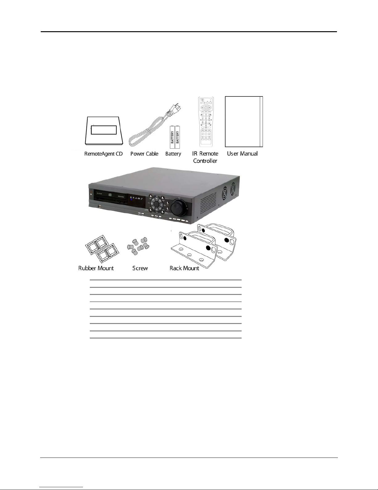
1.1 Getting Started
The following accessories are supplied with the EDNS-3000 series digital video recorder. If any of these items is missing or
damaged, notify your dealer immediately. Keep the packing utilities for moving or storage purposes afterwards.
Qty Accessories
1User Manual
1 IR Remote Controller
1 DigiOp RemoteAgent CD
1Power Cable
2 Power Battery (AAA Size)
1 Rubber Mount Set
1 Rack Mounts and Screws
EDNS-3000
Page 7
DigiOpG2 Digital Video Recorder Page 6
3040-00052
2. Explanations for each function
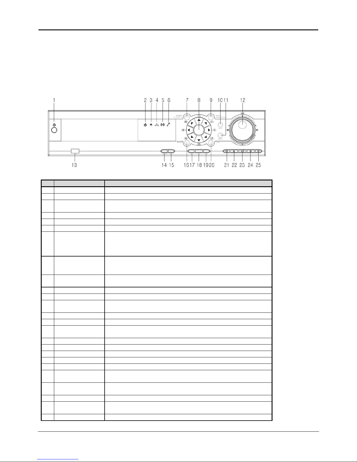
2.1 Front Panel
The buttons on both the front panel of the EDNS-3000 and IR Remote Controller have the same functions. Each button can
activate different functions. The buttons on the front panel of EDNS-3000 may be different in shape than the remote
controller buttons, but the IR Remote Controller can also control the functions controlled by the front panel of the EDNS-
3000.
No. Buttons Functions
1 Power Button Use to turn the Power On/Off.
2 Power LED Shows Power On/Off status of the system (GREEN: Working, RED: Stand-by).
3 HDD LED
Shows if the camera image is being stored into or retrieved from the HDD (Hard Disk
Drive).
4 Network LED LED is lit while the network client(s) (RemoteAgent) is connected to the system.
5 Sensor LED LED is lit when alarm sensor is activated.
6 Audio LED LED is lit while audio data from audio input device is being recorded.
7
SCR MODE
CH1-8/CH9-16
Button to select modes of the arrow buttons.
Whenever the button is pressed, the screen will change to
[1~8 channel mode], [9~16channel mode], or [multiple(split) screen mode].
The default mode is [multiple(split) screen mode].
8
Multiple Screen Mode
Buttons (Arrow
Buttons)
Buttons to select the multiple screen mode as printed, or for use as cursor keys.
9
PAN/TILT/
ZOOM/FOCUS/ IRIS
Button for Camera PAN/TILT/ZOOM/FOCUS/IRIS functions.
10 SETUP Menu to set user environment of the system.
11 SEARCH Search recorded image.
12 Jog/Shuttle
Jog (inner dial): playback frame by frame.
Shuttle (outer dial): Speed up the playback speed of the image (1~32X).
13 USB Port USB interface port to connect external storage equipment.
14 BACKUP Button Button to backup recorded image data.
15 EVENT Button
Shows system’s event information in order of time and brings up event viewer to
search image of the corresponding time.
16 RETURN Button Use to exit from the setting menu or to cancel setting value.
17 OSD Button Button to control the OSD (On-Screen Display).
18 P/T/Z Button For using P/T/Z functions of the camera.
19 SEQ Button Automatic time sequencing for monitor images.
20 ENTER Button Use to enter detail menu, go into the next stage, select or set value.
21
Fast Playback
Backwards
Fast playback the recorded images backwards in the playback mode.
22
Playback Backward
Frame by Frame
Playback the recorded images frame by frame backwards in the playback mode
(playback only I-Frame)
23 Playback Playback recorded images from playback menu.
24
Playback Forward
Frame by Frame
Playback the recorded images frame-by-frame forward in the playback mode.
25 Fast Playback Forward Fast playback the recorded images forward in the playback mode.
Page 8

DigiOpG2 Digital Video Recorder Page 7
3040-00052
2.1.1. Power Button
When the power cable of the product is connected, press this button to turn power on or off.
2.1.2. Power LED
LED to show the power input and status of the system. The LED is red when the system is in stand-by position, but is green
when the system is working and power is being supplied.
2.1.3. HDD LED
LED is blue when the camera image is being stored into or retrieved from the HDD. So, even though the system is continuously
recording, the HDD LED is only lit when actual data is recorded in the HDD. Usually, the LED will be flickering, and this is normal.
2.1.4. Network LED
LED is blue when the system is connected to any network client (RemoteAgent). Light is automatically out when all clients are
disconnected.
2.1.5. Sensor LED
LED is lit when the system has any activated sensor input.
2.1.6. Audio LED
LED is lit when audio data from audio input device is being recorded. Even though the audio input device is properly connected, it
will not light up when audio is not recorded.
2.1.7. SCR MODE or CH1-8 / CH9-16
Use to see the images on the monitor as multiple screens. Whenever this button is pressed, [1-8] (
) group icon, [9-16]
group icon (
), or no icon will be seen on the lower right end of the monitor. When ( ) is indicated on the screen, the
arrow button will be used to select no. 1~8 images. Thus, when icon (
) appears on the screen, the arrow button will be
used to select images from no. 9~16. If the icon is not indicated, the arrow button will be use to select multiple screens (
).
As a default mode, arrow button will be used to select multiple screens.
Note
In case of IR Remote Controller, direction (number) key will be used to input channel no. 1~16. If necessary, select
split screen mode by pressing [SCR MODE] button on the IR Remote Controller.
2.1.8. Select Multiple Screen (Arrow Button)
Select each arrow button and the corresponding multiple screens will appear. Up, down, left, right arrow buttons are used to
move the cursor to “Setting” mode and are also used to increase/decrease the setting value. Furthermore, they are used to
operate camera PAN/TILT Movement, ZOOM IN/OUT, FOCUS FAR/NEAR.
Page 9

DigiOpG2 Digital Video Recorder Page 8
3040-00052
2.1.9. PAN/TILT/ZOOM/ FOCUS/IRIS
Press this button to control PAN/TILT/ZOOM/FOCUS/IRIS value in sequence. This is when PTZ driver has been installed in the
camera.
2.1.10. SETUP
Set the environment of the EDNS-3000 series according to the user requirement.
2.1.11. SEARCH
Search the recorded image by date and time. Refer to “Recording Image Playback Mode” for detail image searching method.
2.1.12. Jog / Shuttle
Jog / Shuttle dial is used to playback recording images. The inner dial is called Jog and the outer dial is called Shuttle. The
Jog/Shuttle dial has two kinds of functions. The Jog is used to find the recording image frame by frame. Turn the Jog dial
clockwise or anti-clockwise (only I-Frame is playback during anti-clockwise) to see the image frame by frame during pause
state. The Shuttle is used to speed up the playback speed of images by clockwise or anti-clockwise. Playback speed is
indicated as x2, x4, x8, x16, x32 on the lower end of the screen.
2.1.13. USB Port
Use to backup recorded images of the EDNS-3000 series by using USB storage device. System software upgrade is possible
with USB storage device.
Note
Refer to “Image Backup” for detailed explanation of USB storage devices supported by EDNS-3000 series.
2.1.14. BACKUP Button
Use to back up images recorded in the HDD to a supported storage device. When this button is pressed, the information from
the backup device connected to EDNS-3000 series (ex. CD-RW drive) will be indicated on the screen.
Refer to “Image Backup” for detailed information about backup.
2.1.15. EVENT Button
Shows system setting changes, alarms, etc., by the order of time and brings up event viewer to search image of the
corresponding time. Refer to “Event Search” for further details.
.
2.1.16. RETURN Button
Use to cancel the password just typed at the setting menu or to return to previous menu.
2.1.17. OSD Button
OSD will initially be displayed on the screen. When the [OSD] button is clicked once, the OSD will disappear. Click [OSD] button
again and the text will reappear.
2.1.18. P/T/Z Button
Click [P/T/Z] button and an icon will appear on the lower right end of the screen image to show P/T/Z status. This is when
P/T/Z driver has been installed.
2.1.19. SEQ Button
Press [SEQ] button and screen will automatically change. Refer to “Settings” for automatic sequencing interval (does not work on 16
split screen mode).
2.1.20. ENTER Button
The [Enter] button is used to go into the next stage, select value, or setting.
Page 10
DigiOpG2 Digital Video Recorder Page 9
3040-00052
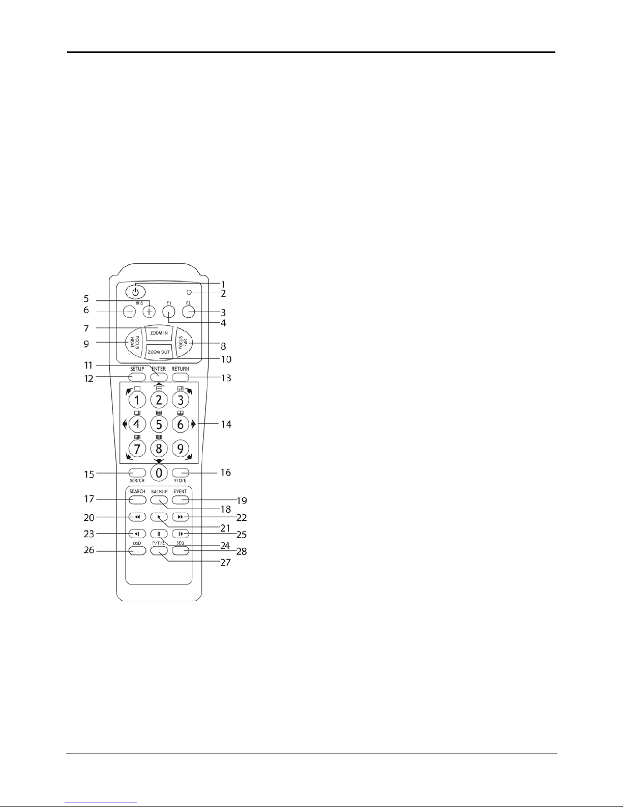
2.2 IR Remote Controller
The function buttons of the IR Remote Controller are the same as function buttons on the front panel as shown below.
No.
Functions
Power Button 1
Activating LED 2
F2 (Reserve Button) 3
F1 (Reserve Button) 4
IRIS+ (Open Iris) 5
IRIS– (Close Iris) 6
ZOOM IN (Narrow) 7
FOCUS FAR 8
FOCUS NEAR 9
ZOOM OUT (wide) 10
ENTER 11
SETUP 12
RETURN 13
Select Number Button /
Multiple Screen 14
SCR / CH Button 15
F/O/E Button 16
SEARCH Button 17
BACKUP Button 18
EVENT Button 19
Page 11
DigiOpG2 Digital Video Recorder Page 10
3040-00052
Fast Playback Backwards Button 20
Playback Button 21
Fast Playback Forward Button 22
Playback Backward Frame by
Frame 23
Pause Button 24
Playback Forward Frame by Frame 25
OSD Button 26
P/T/Z Button 27
SEQ Button 28
Note Button #16: F/O/E Button (use only on remote controller)
The object in the recorded image might show the feathering effect during frame playback because images at
720x480(PAL:720×576) resolution have higher vertical resolution than 640x240(PAL:640×288) or 352×240
(PAL:352×288). The feathering of the image can be solved when only one of two Fields (Odd, Even Field) is
selected. Default is frame playback. When the button is pressed, it will change to Odd Field Playback-> Even Field
Playback-> Frame Playback order.
Note
To use the IR Remote Controller, synchronize front panel button and IR remote controller by inputting the initial ID.
The user requires setting the ID only once. Refer to “Settings” for detailed information about ID input.
Note
When the IR Remote Controller is used to change the channel, no. 1 button is also used to select channels after
number 10. Press no. 1 button and it will be ready to add another extra number. Example, press no. 1 and once it is
ready to add another no., press 2. Then, channel will change to channel no. 12. But press no. 1 button for few
seconds and the channel will go to no. 1 channel.
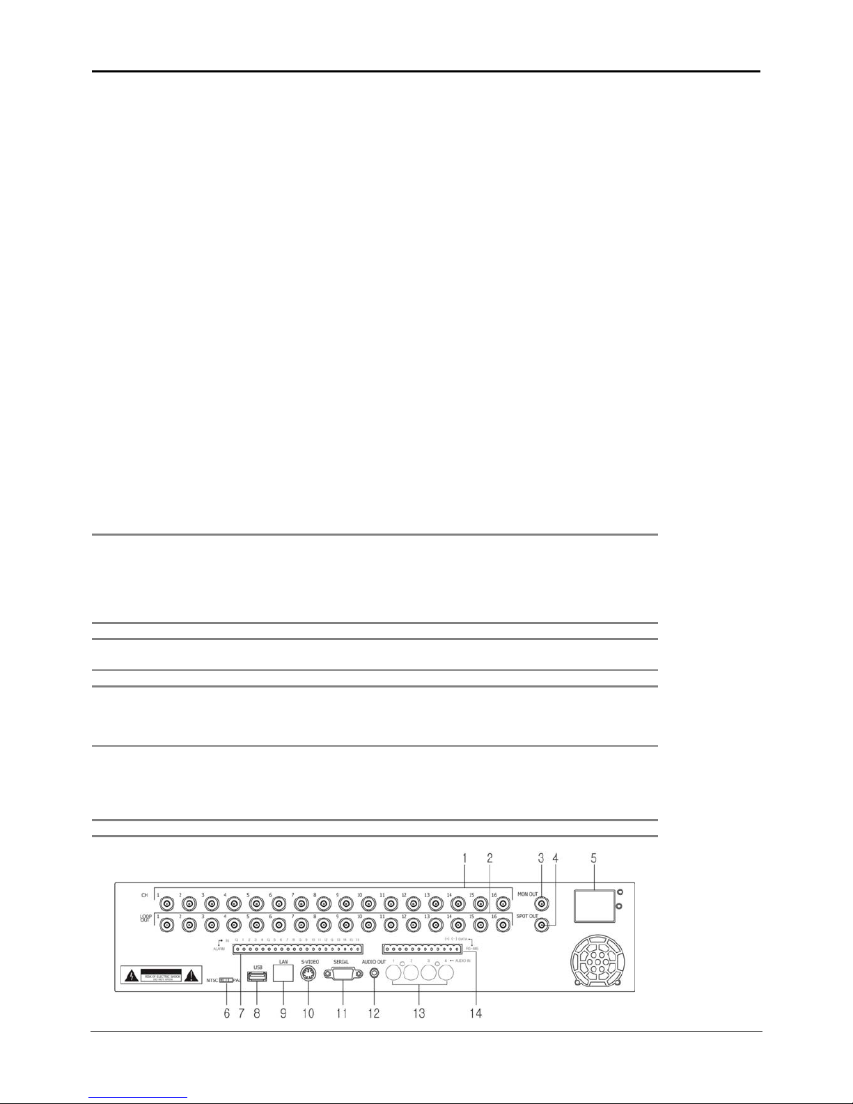
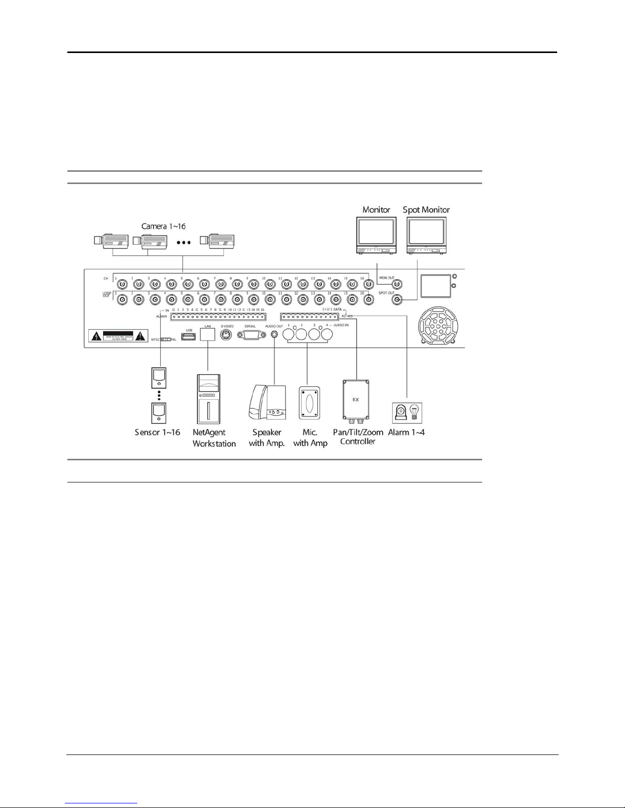
2.3 Rear Panel
The following is the rear panel of the EDNS-3000 series system. The picture below is EDNS3000-16EP model.
Note
The configuration differs according to the model.
Page 12

DigiOpG2 Digital Video Recorder Page 11
3040-00052
No. Name Functions
1 Camera Input (BNC) Connect to Camera (supports NTSC/PAL)
2 LOOP OUT
Camera images of each channel will be outputted as is (also used when the
corresponding image is required for other product)
3 MON OUT
Connect to the main monitor for camera image
surveillance/management/playback
4 SPOT OUT Use to output the entire surveillance screen one by one, in an interval
5 Power Input Connect main power cable
6 Select NTSC / PAL Select the signal system (NTSC/PAL)
7 SENSOR Input Connect 16 external input sensors (supports N/O or N/C)
8 USB Port Connect USB device
9 LAN Port RJ-45 socket for 10/100 Ethernet connection
10 S-Video Output Secondary main monitor output
11 Serial Port RS-232C port
12 Audio Out Connect Audio Output Device (with Amp.)
13 Audio In Connect Audio Input Device (with Amp.)
14 Alarm Out / P/T/Z Connect P/T/Z receiver(RS-485) and/or relays
Note
Ensure that the specification for the EDNS-3000 agrees with the specification for the peripheral devices. For details
about adding additional peripheral devices, consult your dealer.
Page 13

DigiOpG2 Digital Video Recorder Page 12
3040-00052
2.3.1. Camera
Connect BNC plug of camera video cable into the desired BNC input.
Note
Camera input voltage level is 1Vp-p±10%.
2.3.2. LOOP OUT
Use to apply the video of camera input to other device. Without using a video distributor, the same image can be connected
to the camera input of other product.
2.3.3. MON OUT
Connect the BNC cable of the monitor to MON OUT BNC cable of the rear panel.
2.3.4. SPOT OUT
The spot monitor can only be used to display input images in automatic interval mode. Refer to “Settings” for automatic
interval time setting of spot monitor.
2.3.5. Power Input
Connect to main power cord of the system.
Caution
Before plugging-in the power cord to the system, check if the power is in accordance with the system
specification (Single Phase AC 115~230V)
2.3.6. Select NTSC / PAL
Turn off the power of the EDNS-3000 series and select the NTSC/PAL switch correctly. Then turn on the power again.
2.3.7. SENSOR Input
Connect sensor (dry contact type). Separate the terminal block and wire all devices to desired pins, before connecting the terminal
block again. Connect each ground (GND) line to “G” pins.
Note
Support both N/O (Normal Open) and N/C (Normal Close). If connected sensor is not functioning, ensure wiring is
correct.
2.3.8. USB Port
Connect USB storage device.
Note
Refer to “Image Backup” for details on the supported USB storage device of EDNS-3000.
2.3.9. LAN Port
Connect RJ-45 jack of LAN cable to LAN port. Network has to be TCP/IP base 10/100BASE-TX Ethernet LAN (Local Area
Network), Internet or exclusive line, and IP address should be fixed one. Consult network administrator for proper network
configuration.
2.3.10. S-Video Output
One additional main monitor can be installed by using the S-Video output. Use the S-Video cable to connect the EDNS-3000
with the monitor, which has S-Video Input.
2.3.11. Serial Port
Port for RS-232 signal output.
2.3.12. Audio Out
Connect audio output equipment.
Note
Use of audio output device with an amplifier is recommended
2.3.13. Audio In
Connect Audio Input device.
Note
Input voltage of audio input device is line level.
Use of audio output device with amplifier is recommended.
2.3.14. Alarm Out / P/T/Z
Connect various alarm devices controlled by relay output. EDNS-3000 series supports RS-485 for P/T/Z control.
Page 14

DigiOpG2 Digital Video Recorder Page 13
3040-00052
Note
Refer to the following picture to control P/T/Z controller. General wiring of P/T/Z controllers is as follows. However,
the wiring of different P/T/Z controller may differ. Be cautious that the P/T/Z controller will not function properly
when wiring is incorrect.
Consult your dealer to use other than RS-485.
EDNS-3000
Page 15
DigiOpG2 Digital Video Recorder Page 14
3040-00052
3. Installation
3.1 Connecting Peripheral Devices
This section describes how to efficiently hook up peripheral devices for usage with the EDNS-3000 series.
Install the EDNS-3000 series on flat surface. If required, attach the rubber mount for installation. If 19-inch rack is used, it is
recommend to install the system on shelve and use 2.5~3U (1U=1.75 inch or 4.45cm) space for proper ventilation.
Note
Install system in location with good ventilation to prevent overheating.
Caution
Depending on the grounding, the coaxial cable connecting to the camera has danger of electric shock. Shut
down power of the system completely (unplug the power cable) before connecting video cable to BNC port.
Page 16

DigiOpG2 Digital Video Recorder Page 15
3040-00052
3.2 System Startup and Shutdown
3.2.1. System Startup
After connecting all peripheral devices, connect power cord to EDNS-3000 series for system startup. The power
will be turned on automatically within 5 seconds of power cord being connected. However, power will not be turned on
automatically, if power button was previously turned off by user. In that case, the power button must be pressed again
to restore power.
3.2.2. System Shutdown
To turn off the power, press the power button for proper shutdown of the system. Do not turn off the power by pulling the
power plug.
CAUTION
In case the power plug is pulled off while the system is operating, the currently recording file may not be
closed properly. In addition, even though Journaling File System is not damaged, index information required
for quick file search may not be saved. Of course, Auto Recovery System will recover these files during the
next booting. This process might take between a few seconds to a few minutes. Therefore, turn off system
power by pressing the power button to prevent malfunction.
3.2.3. Countermeasures after abnormal shutdown
EDNS-3000 series has been designed to operate for long periods without a problem.
The operation of the system can be locked, when major parts (such as hard disk) function abnormally due to external electric
shock, physical damage, or other various reasons.
The system stops operating during abnormal situations, and the internal watchdog circuit is activated in order to reset the
system for rebooting within 2 minutes. The system will then recover normally. It will also automatically reboot even when
there is power failure. However, if major parts (such as hard disk) are physically damaged, it is impossible to recover normally.
This will cause continuous rebooting by watchdog or deadlock without reset.
Countermeasures for abnormal discontinuation are as follows.
1. In case the power cannot be turned off, turn off by pulling the power cord.
2. Wait for about 10 seconds and reconnect the power. Ensure the system is functioning properly.
3. Consult your dealer if system is not functioning properly after reconnecting power.
3.2.4. Automatic file testing and recovery
By using Auto-Scan and Auto-Recovery, the files damaged due to abnormal shutdown will be recovered automatically.
Note
Generally, when all files in the hard disk have been closed properly during normal shutdown, it will take only a few
seconds to examine the files after rebooting. It will take few minutes or more to recover the files if recovery is
required, however.
Page 17

DigiOpG2 Digital Video Recorder Page 16
3040-00052
4. Operation
4.1 Log-in
Check the power connection. The system can be used after power-on.
EDNS-3000 series has various setting categories. The administrator can set the system password and <User> to prevent
unauthorized changes to setting values and alteration to recorded file.
Below is first login box indicated on the screen after electric power is on. Refer to “System-Password” for how to set and
change <User> password.
Only <Administrator> can enter the setting menu (<User> cannot).
Before entering the setting menu, <Administrator> password must be entered in the box as displayed below. Refer to
“System-Password” for how to set and change <Administrator> password.
Note
Be cautious not to forget the Administrator password. If it is forgotten, consult your dealer.
Page 18

DigiOpG2 Digital Video Recorder Page 17
3040-00052
4.2 Real time Live Mode
Real time live image can be seen after power up.
Note
Both the IR Remote Controller and the front panel button can be used in EDNS-3000 series.
4.2.1. Screen configuration
1
2
Above is the typical real time mode screen. Press [OSD] button on the front panel or IR Remote Controller to control the
display of OSD. Whenever the button is pressed, the display of OSD will toggle between appearance and disappearance.
The following is the explanation of each item displayed on the screen from single screen to 16 split screen.
1. Channel Name: Shows camera title of the channel. Refer to “Setting-> Camera -Title” for how to set and change
camera title.
2. Date and Time: Indicates present date and time of the system. When the recorded data is playback, indicated date
and time will be those of the recorded image currently displayed.
Page 19

DigiOpG2 Digital Video Recorder Page 18
3040-00052
4.2.2. Single screen mode
To see an individual screen, press the [SCR MODE] button on the front panel or IR Remote Controller. Single screen mode
must be selected to hear sound from the audio device that is connected to the system, or to see the recorded image.
Press the arrow button on the front panel to change channels.
Note
If split screen mode is selected when an arrow key is pressed, press the [SCR MODE] button.
Press the number button in the IR Remote Controller and the corresponding channel image can be seen. For example, the
following image is seen when number 2 is pressed.
Note
Check connection status of the camera BNC cable or monitor output cable on the rear panel when image of the
monitor cannot be seen.
Page 20

DigiOpG2 Digital Video Recorder Page 19
3040-00052
4.2.3. Split Screen Mode
In the EDNS-3000 series, the user can see several camera images in various multiple screen formats. Press each button and the
corresponding images will be seen in split screen mode.
Note
To see split screens, press the [SCR Mode] on the front panel or IR Remote Controller.
To see the camera image in various split modes, press corresponding arrow buttons. The pictures below correspond to the
buttons on the front panel and IR Remote Controller.
Front Panel Arrow Button
IR Remote Controller Number Button
Button Multiple Screen Button Multiple Screen
1 Screen
4 Screens
6 Screens
8 Screens
9 Screens
10
Screens
13
Screens
16
Screens
Page 21

DigiOpG2 Digital Video Recorder Page 20
3040-00052
4.2.4. See Operating Status
In real time live mode, icons or messages will be indicated on the screen to notify the system mode or status.
Below are the icon categories, which are indicated on the monitor.
Fast Backward Playback Alarm Zoom (In/Out)
Playback Backward Frame by
Frame
Direction Key Focus
Pause
Select Images from No. 1~8
Channels
Iris
Playback
Select Images from No. 9~16
Channels.
Automatic Screen
Sequence
Fast Forward Playback Split screens P/T/Z Controller Activates
Playback Forward Frame by
Frame
Note
When an alarm occurs in the connected channel, the [Alarm] icon will appear on the right bottom side of the
screen and “Channel Name” will be indicated in red. The alarm icon will disappear, but the channel number will
remain in red for a while when the user enters setup menu, or tries to backup during alarm.
The number buttons on the IR Remote Controller can be used as direction keys.
While [Direction Key] icon is being displayed, the number keys on IR Remote Controller can be used as arrow keys.
When IR Remote Controller is used for P/T/Z control, press [P/T/Z] button to display [P/T/Z] icon and, then, press
[SCR/CH] button to display [Direction Key] icon.
Page 22

DigiOpG2 Digital Video Recorder Page 21
3040-00052
4.3 Recorded Image Playback Mode
The user can select date and time to search for a certain file within the recorded image of the EDNS-3000 series.
4.3.1. Recording Image Playback
To playback recorded image, press (@) button on the front panel or IR Remote Controller. Press the playback button and the
latest recorded image will be playback.
Use the Jog /Shuttle on the front panel to playback recorded file easily.
Turn the Jog and the recorded file can be playback frame by frame backward and forward.
Turn the Shuttle and recorded image speed can be increased by 2, 4, 8, 16 or 32 times backward and forward.
4.3.2. Search Date/Time
The User can search date and time to playback recorded image.
Press [Search] button on the front panel or IR Remote Controller and the following screen, showing calendar and time graph,
will appear.
Following the sequence below to search date and time:
1. Select the date with recorded image by clicking the calendar with the arrow button. The date with recorded image
will be indicated in white.
2. Move the green arrow to date required before pressing the [Enter] button on the front panel or IR Remote
Controller.
3. Next, move the green arrow (located on the time graph below the calendar) to the desired time.
4. One hour is divided into 15 minutes increments. Move the green arrow to the desired time.
5. Upon moving the green arrow, click the [Enter] button. The image for the corresponding time will be shown in
pause state.
6. Press the [Play] button to playback the recording image or use the Jog/ Shuttle to search the exact time.
Page 23

DigiOpG2 Digital Video Recorder Page 22
3040-00052
4.3.3. Event Search
EDNS-3000 series uses the Event Log to document important events such as sensor activity, system On/Off, changes in
settings. The Event search function is used conveniently to find an image corresponding to a particular event.
Note
In order to leave and search alarm history on the Event Log, turn on the [Alarm In] function on the setting menu.
Refer to “Setting->Alarm Input” for detailed instructions.
To check the event history, press the [Event] button on the front panel or IR Remote Controller. Press the button and the
following Event Viewer will appear.
Occurred date, time (hr: min: sec), (S: Standard D: DST) and signaled alarm will be indicated on the Event Viewer screen. Use
the arrow button on the front panel or the IR Remote Controller to move to the recorded image corresponding with a
particular event. The up and down arrow buttons are used to move the selection bar up and down. The left and right buttons
are used to move page by page.
The following is the category as indicated on the Event Viewer.
1. Alarm in Signal (for each channel) - Alarm is signaled on sensor [1] (Alarm (Sensor) Number)
2. Enter P/T/Z Mode (for each channel) -Start P/T/Z on CH2 (Channel Number)
3. Setup Menu Setting - Changed system settings
4. System Start (Power on), Shutdown (Power off) - Starting system, Shutdown system
5. System Upgrade - Upgraded to 1.0.4 (version)
6. Change Resolution (Recording Image Size) - Image Size is changed to 640x288 (Resolution)
7. Change Date and Time - Date or time is changed
8. Log on Information or Authority (Connect by User or Admin) - Logged on with <User (or Admin)> privilege
9. Change Network address - Network address is changed
10. Go to Factory Default - Reset System Settings
11. Log off Information - <User> had been logged off
Press [Enter] or [Play] button on the front panel or IR Remote Controller after selecting date and time to see recorded image
for the time chosen. If there is no recorded image for the corresponding time, the image of the closest time will be playback.
Note
When the alarm does not activate and the alarm input is set properly, check the alarm wiring on the rear panel.
Then, check whether the sensor input status is functioning properly.
Page 24

DigiOpG2 Digital Video Recorder Page 23
3040-00052
5. Image Backup
There are two ways to backup the recorded images of EDNS-3000 series. The first is by using internal CD-RW drive (option).
The second is by using USB external storage device.
5.1 CD Backup
Use the CD-RW attached to the EDNS-3000 series to backup the recorded images.
Press the [Backup] button on the front panel or IR Remote Controller and the following screen will appear.
Note
The specifications will show differently, depending on the model of CD-RW drive. Refer to the CD-RW drive manual
for a detailed explanation.
When the CD-RW drive is not installed or not properly connected, the following error message will appear. The following error
message will also appear if CD-R media (Blank CD) for storage is not on the CD tray.
Note
Consult your vendor if you require detailed information on the CD-RW.
Page 25

DigiOpG2 Digital Video Recorder Page 24
3040-00052
Enter each item on the screen below to backup recorded images.
1. Select the recording start time for backup.
2. Also, select the recording end time for backup.
3. Select channels to backup. The user can select several channels together, but if the backup data capacity is more
than the storage capacity, backup will not proceed. Select the channel by using the cursor and pressing [Enter]
button.
4. After selecting all the items, press [Next] button to proceed to the next screen.
Note
Input the time by pressing the arrow (up, down, left, right) button of the front panel on the IR Remote Controller.
When the channels are not selected, error message will appear as shown below.
Page 26

DigiOpG2 Digital Video Recorder Page 25
3040-00052
Press [Enter] after correctly selecting all the items correctly for backup. Proceed as indicated below.
The following is the list of media supported in the internal CD-RW of EDNS-3000 series.
CD-R :
Acer, AMT, CMC, Kodak, LeadData, Maxell, Mitsubishi Chemical, Mitsui, Nan Ya, Philips, Princo, Prodisc, Ricoh,
Ritek, Sony, Taiyo Yuden, TDK, Verbatim, Yamaha
CD-RW :
Acer, AMT, CMC, Digimaster, Maxell, MaxMax, Melody, Mitsubishi Chemical, Philips, Plextor, Prodisc, Ricoh, Ritek,
Sony, TDK, Traxdata, Verbatim, Yamaha
When the backup is completed, the following message will appear.
Page 27

DigiOpG2 Digital Video Recorder Page 26
3040-00052
5.2 USB External Storage Device for Backup
EDNS-3000 series supports USB. Connect external storage device to the USB port on the front or back panel.
Click [BACKUP] button on the front panel and the screen below will appear.
Note
Below is a lists of USB external storage devices supported by the EDNS-3000 series. Consult your vendor if the
devices do not operate properly.
1. AOpen CRW5224 External CD-RW Drive
2. AOpen EHW-4048U External CD-RW Drive
3. SONY CRX2100U External CD-RW Drive
4. Plextor PX-W4012TU External CD-RW Drive
5. DVICO MOMOBAY CX-2 2.5" External HDD
6. UNiCORN Portable HDD HD-250 External HDD
7. OTI FELLOW Flash Disk Drive
8. Hanbit STORiUM N Flash Disk Drive
EDNS-3000 series does not support DVD±RW drive. Should use of DVD±RW drive be required, use CD-R media
versus DVD+RW or DVD-RW.
The following error message will appear if the USB storage fails to backup.
Page 28

DigiOpG2 Digital Video Recorder Page 27
3040-00052
When the USB storage device is connected incorrectly, the following message will appear.
If there is not enough free disk space in the USB storage device, the following error message will appear.
The following message will appear when the image backup of the USB storage device has been completed.
Note
To use USB storage for backup, use FAT file system. If the storage device is set to NTFS file system, backup will fail.
Note
DO NOT connect two or more external USB storage devices to the system. If not, the system may not recognize
those devices correctly. In addition, some USB hubs cannot be recognized correctly.
Page 29

DigiOpG2 Digital Video Recorder Page 28
3040-00052
6. Settings
To operate EDNS-3000 series, appropriate setting values in the setting menu are necessary. Users can either input or change
the setting values listed in the table below.
Main
Classification
Sub Classification Setting Category Default
Image Size PAL:640x240 (NTSC:640x288)
Page Sequence 3
IR Remote ID 10
P/T/Z Protocol None
General
Spot-Out Dwell 1
Date and Time
Date Format Year, Month, Day
Time Format 24 Hours
Date and Time
Daylight Saving None
LAN
Networks
Modem
Admin
User
System
Passwords
Network 1234
Record On
Frame PAL:6
Quality 70
Recording
Sensitive 70
Title CH#
Start 0Title & Schedule
End 24
Bright 50
Contrast 50
Color 50
Color
Tint 50
Audio Off
Aud-CH 1
Camera
Audio & P/T/Z
P/T/Z Address 0
Camera# Off
Start 0
End 24
Alarm Input
Ty pe N / C
Relay# Off
Alarm Mode Duration
Alarm
Alarm Output
Dwell N/A
System Information
LAN
TFTPSystem Upgrade
CD-ROM
Tools
System Default
Log Off
Quit
Close Menu
Page 30

DigiOpG2 Digital Video Recorder Page 29
3040-00052
6.1 System-General
Set general environment of the system.
6.1.1. Image Size
Select the recording resolution. Resolution is the number of pixels for length and width, which are used to display one image.
Resolution displays the pixel number in (width)×(length), and the user can select one resolution among 352×240, 640×240,
and 720×480. Default is 640×240.
The bigger the resolution number, the better the quality that is displayed. Resolution of 352×240 is VHS quality, and 720×480
with a high-resolution camera is DVD quality. Selecting appropriate resolution is important since higher quality images require
more storage space, and shortens the recording period.
Note
Since the required storage space is proportional to the area of the image (width×length), 640×240 takes up
approximately 1.8 times bigger space than 352×240, and 2.5~3 times bigger for 720×480. Therefore, the recording
period decreases when selecting the high resolution.
Note
Even with the same resolution, total recording period can vary depending on characteristics such as recording
quality, motion detection threshold and average motion of objects in the image, complexity of image, and video
noise of the images. However, EDNS-3000 series controls the average size of images not to exceed the following
maximum limit for each resolution in every occasion.
352×240 : Normally 3~5KB, Max. Average 8KByte/image
640×240 : Normally 5~10KB, Max. Average 13KByte/image
720×480 : Normally 6~16KB, Max. Average 15KByte/image
If the average size exceeds the maximum, the system automatically reduces the recording quality to maintain below
maximum. The issue of reduced total recording time due to increased size caused by nighttime camera noise, is
therefore eliminated.
Page 31

DigiOpG2 Digital Video Recorder Page 30
3040-00052
6.1.2. Page Sequence
Set sequencing period when automatic screen sequencing mode is selected in real time live mode. Page Sequence indicates
switching over from selected screen to the next screen in fixed period of time. For example, Page Sequence is operated in 4split screen, the next screen (5-8 channel, 9-12 channel, 13-16 channel) is displayed after certain fixed period of time. This
status can be on/off by pressing the [SEQ] button on the system front panel or IR remote controller. Possible setting range is
1~60 seconds, and the default is 3 seconds.
6.1.3. IR Remote ID
Set IR remote controller ID. To operate the system easily using IR remote controller, IR remote controller ID should be set first.
The setting procedure of IR remote controller ID is shown below.
1. Insert battery in IR remote controller. (AAA Size ×2)
2. Press [SCR / CH] and [F/O/E] button on the IR remote controller at the same time.
3. Check if the LED on IR remote controller is lighted.
4. Press two-digit number (01~99) to set IR remote controller ID.
5. Assign the identical ID number using front panel arrow keys on the system.
6. Save the ID by pressing [Save] button on the screen.
Note
Setting the IR remote controller ID is necessary only once after purchasing the system.
Note
All systems manufactured in the factory have identical ID as initial value. Therefore, one IR remote controller can
control several systems when using the initial value. To protect such circumstances, it is recommended to set
different ID for each system. Since ID change on the IR remote controller is easy, it is convenient to operate several
systems separately by changing the ID using one remote controller.
6.1.4. P/T/Z Protocol
Set the protocol to control the P/T/Z controller connected to P/T/Z port on the back panel. P/T/Z controller is also called receiver
or RX if it becomes separated from camera. Default is NONE, which indicates that the P/T/Z controller protocol is not set.
Protocol currently supported is shown below.
1 ERNITEC 2400 baud rate no parity 8bit 1 stop bit
2 Panasonic 19200 baud rate no parity 8bit 1 stop bit
3 Pelco P 4800 baud rate no parity 8bit 1 stop bit
4 Pelco D 2400 baud rate no parity 8bit 1 stop bit
5 Sensormatic 2400 baud rate no parity 8bit 1 stop bit
6 Smart Scan 9600 baud rate even parity 8bit 1 stop bit
7 VC_C4 9600 baud rate no parity 8bit 1 stop bit
8 Vicon 4800 baud rate no parity 8bit 1 stop bit
Set the controller address correctly for each channel after setting the protocol.
6.1.5. Spot-Out Dwell
Set the switchover period of the Spot-Out channel to 1~60 seconds.
Page 32

DigiOpG2 Digital Video Recorder Page 31
3040-00052
6.1.6. Save
Press the [Save] button when saving the setting value for each menu screen. Setting values won’t be saved when exiting the
menu without pressing the [Save] button. Functions of [Save] buttons in each menu screen are identical.
6.1.7. Restore
Previous values are restored to the values before the [Save] button is pressed. Press the [Restore] button to cancel the current
setting values and to return to previous values. Functions of [Restore] buttons in each menu screen are identical.
6.1.8. Cancel
Cancel the setting values in each menu screen. Functions of [Cancel] button in each menu screen are identical.
6.1.9. Clear
Deletes the setting values inputted in each menu screen. It is used to delete the incorrectly typed password.
Functions of [Clear] buttons in each menu screen are identical.
6.1.10. Default
Return to the initial value. Be cautious when pressing the [Default] button since all the setting values will be set to the initial
value. Functions of [Default] button in each menu screen are identical.
Page 33

DigiOpG2 Digital Video Recorder Page 32
3040-00052
6.2 System-Date and Time
Set time and date of the system. Press arrow button to move the cursor to the desired position and to set correct and accurate
value. Press [Save] button at the bottom of the screen to save the setting contents.
6.2.1. Date and Time
Input the current time and date accurately since the time and date of the system plays an important role in solving any
problem with recorded image or event log.
The current time and date is stored in each recorded images with precision, and they are displayed during playback. Be
cautious: Although the time and date stored in recorded images are wrong, they cannot be altered afterwards due to
encryption.
Note
Users can change the time and date to the future without any problem. However, difficulty arises when changing it
to the past (the same files might exist in the hard disk). Therefore, under complex recording setting, unexpected
problems might arise in the system.
To solve such problems, EDNS-3000 series automatically deletes all the future files from the modified time and
date. Consequently, be cautious when changing the date and time to the past. In addition, every function in the
system operates normally since this procedure is handled in the background.
Note
When a long time has elapsed after a correct setting of the system time and date, the system time can go fast or
slow. According to the specification of the RTC (Real Time Clock) used in EDNS-3000 series, the time difference can
be 113 seconds per month in maximum. Therefore, the periodic (more than once per month) correction of the
system time and date is required for the maintenance of accurate system time.
6.2.2. Date Format
Set the date display format. Select the desired format in the date display format after pressing arrow button.
6.2.3. Time Format
Set the time display format. Time format can be selected either by 24-hour or 12-hour base (AM or PM).
Page 34

DigiOpG2 Digital Video Recorder Page 33
3040-00052
6.2.4. Daylight Saving
Select the daylight saving time for each country. Daylight saving time setting is automatically processed when country is
selected. Supported countries are displayed in the table below.
No. Country Representative Region No. Country Representative Region
1 None GMT 2 Australia Australia/Melbourne
3 Austria Europe/Vienna 4 Belgium Europe/Brussels
5 Brazil Brazil/East 6 Canada Canada/Eastern
7 Denmark Europe/Copenhagen 8 Egypt Egypt
9 Finland Europe/Helsinki 10 France Europe/Paris
11 Germany Europe/Berlin 12 Greece Europe/Athens
13 Israel Israel 14 Italy Europe/Rome
15 Mexico Mexico/General 16 Holland Europe/Amsterdam
17 Norway Europe/Oslo 18 Poland Europe/Warsaw
19 Portugal Portugal 20 Russia Moscow
21 Spain Europe/Madrid 22 Sweden Europe/Stockholm
23 Switzerland Europe/Zurich 24 UK Europe/London
25 US US/Eastern
Page 35

DigiOpG2 Digital Video Recorder Page 34
3040-00052
6.3 System-Network
Set the network environment of the system. An example of a LAN is shown below.
Note
Consult your vendor if user wants to use a modem.
6.3.1. Connection Type
Select either LAN or Modem by pressing the arrow button. Move to next item by pressing [Enter] button after selection.
6.3.2. Host Address
Input the IP address assigned to EDNS-3000 series system.
Note
Use fixed IP for system IP.
For system IP, use the IP that is not used by other PC or DVR.
6.3.3. Subnet Mask
Subnet Mask address recognizes the subnet to which the system belongs. Default is 255.255.255.0. Consult network
administrator for accurate information.
6.3.4. Default Gateway
This is the IP address of the network router or gateway. It is required when the user wants to connect through the external
router from the remote. Default is 192.168.0.1.
Note
Consult your vendor if network connection configuration is required.
Page 36

DigiOpG2 Digital Video Recorder Page 35
3040-00052
6.4 System-Passwords
Set passwords for <Admin> and <User>, and also set <Network> password to allow connections from RemoteAgent.
Set the password after selecting [Admin], [User], and [Network] by pressing arrow button.
6.4.1. Select
Select password to be set. Admin and user can have only one account for each.
6.4.2. Old Password
Input the old password.
6.4.3. New Password
Input the new password. Up to 8 digits can be inputted.
6.4.4. Confirm
Input the new password once more for confirmation.
Note
Press [SCR MODE] button on the front panel (or [SCR/CH] button on IR remote controller), then press arrow
(up, down, left, right) button (or number buttons in IR remote controller) to input the password.
Page 37

DigiOpG2 Digital Video Recorder Page 36
3040-00052
6.5 Camera-Recording
Set the general environment related to camera usage. The screen below shows the setting related to recording.
720×480 640×240 352×240
Model
Max FPG Max FPG Max FPG
3120-16EP 60 15 120 30 240 60
3120-16EPC 60 15 120 30 120 30
3240-16EP 30 8/7 60 15 120 30
3240-16EPC 30 8/7 60 15 120 30
* FPG : Frame per Group
6.5.1. Record
Controls whether recording of the channel will be done or not. [ON] is to record and [OFF] is not to record. If recording is not
required, even when the video of the channel is feeding, set [OFF] for the channel. Then, recording of the channel stops
without pulling camera BNC cable off. [ON] or [OFF] can be selected. The default is [ON].
Page 38

DigiOpG2 Digital Video Recorder Page 37
3040-00052
6.5.2. Frames
Set the desired number of recorded images per second for the connected camera. The total number of recorded images per
second, per group, has an upper bound (NTSC: 30fps, PAL: 25fps), which cannot be exceeded. Remaining frame number of
the group is displayed at the left bottom of the screen whenever the frame number of each camera is modified.
Note
Each camera belongs to one and only one group and can share the total frame per second of the group up to
25/PAL or (30/NTSC). In case of alarm recording the recording speed of alarmed camera is automatically increased
to a possible maximum value. The value can be calculated as follows: If the number of alarmed cameras is
n
and
the signal system is PAL, then the recording speed of alarmed camera is
[
]
nn /1)4(25
×−−
. For example, if
there is one alarmed camera, the channel will be recorded at the speed of 22 fps while other 3 channels will be
recorded at the speed of 1 fps. Likewise, if there are two alarmed cameras, those channels will be recorded at the
speed of 11 fps each while other two channels will be recorded at the speed of 1 fps.
The connecting channels of each group are shown below.
Group 1=Channel number 1,5,9,13 / Group 2= Channel number 2,6,10,14
Group 3=Channel number 3,7,11,15 / Group 4= Channel number 4,8,12,16
Setting value will not be saved if the frame number setting exceeds 25 fps. The remaining frame number at the left
bottom of the screen is displayed as [-] if the frame number setting exceeds 25 fps. In this case, error message
appears, and frame number will not be saved even though [Save] button is pressed. Set the frame number so that
the total frame number does not exceed 25 fps.
To set frame number by each group, check the remaining frame number after setting the frame number for each
group, then press the [Save] button. The setting value will not be saved if there is wrong setting for any group.
6.5.3. Quality
Set the recording quality for the corresponding channel according to resolution setting by tenth (10-unit) between 10~100. In
general, 60~90 is the average extent for setting, where 10 is the lowest quality, and 100 is the highest quality.
The setting value directly influences the byte size per image. For example, the byte size decreases as quality goes lower. In this
case, blocking (mosaic) phenomena tends to appear, which is the artifact caused by high compression. In contrast, blocking
phenomena disappears as quality goes higher. In this case, the required storage space per image increases, which leads to
shortening of total recording period. Therefore, give consideration to the necessary recording period, importance of each
camera image, and quality of analog signal when setting the recording quality. If extending the recording period in high
quality, refer to 6.5.4. The byte size decreases when the sensitivity setting decreases.
When the quality increases over 80, picture quality increases in small degree, but the byte size increases to great extent.
Be cautious while using low performance camera, since it tends to be much noisier at nighttime and might cause the increase
of byte size when high quality value is set for the camera.
6.5.4. Sensitivity
Set the motion sensitivity value based on motion detection between 10~100. Higher value saves any movement without
skipping, and lower value skips small movements to extend the recording period.
The default is 70, and it is recommended not to change, with the exception of special cases. To change this value, refer to the
“Sensitivity Setting” in the appendix to get full understanding, and try different values to find the most suitable value
corresponding to the circumstances.
Page 39

DigiOpG2 Digital Video Recorder Page 38
3040-00052
6.6 Camera-Title & Schedule
Set the title of the connected camera and recording schedule.
6.6.1. Title
Input the camera title of selected camera. Inputted camera title is displayed as OSD (On-Screen Display) and is also stored in
the recorded files afterwards. Therefore, when the file is played in the system or remote site, the camera title will be indicated
as that stored in the file during recording.
Default camera title is “CHn” where n is the channel number. It can be up to 16 characters maximum including letters, capital
letters, numbers, or spaces. The screen below indicates a keyboard in which to input letters for Title.
6.6.2. Start & End
Set recording start and end time for the camera. Start time indicates that the recording is started on exact time (0 minutes 0
seconds), and end time indicates the images are recorded until the assigned time (59 minutes 59 seconds). Hour is displayed
in 24-hour unit, default is “0~24”. That is, if it is recorded 24 hours every day.
It will record normally even if the start and end time is reversed. For example, if the schedule is set as “18~9”, it records from
18.00 to 09.00 the next day for every day.
Note
Even if a camera is not set to record according to a schedule, it can record by means of sensor-activated recording.
Select the Record ‘Off’ in the “Camera-Record” when you want sensor-activated recording only.
Page 40

DigiOpG2 Digital Video Recorder Page 39
3040-00052
6.7 Camera-Color
Set the brightness, contrast, color and tint of the connected camera.
6.7.1. Bright
Adjust the brightness (shades) of the channel. If the entire image is dark or bright to a great extent, adjust to the adequate
value. Setting values are 1~100.
6.7.2. Contrast
Adjust the contrast, which is the ratio of brightness to darkness of the image. Greater the value, bright side becomes brighter,
and dark side becomes darker. In case the value is increased to the extent where too much saturation is not observed in the
image, higher contrast can be helpful to display the image vividly. Setting values are 1~100.
6.7.3. Color
Adjust the color density. In most cases except for the deterioration of cameras or very low quality cameras, the adjustment of
this value is not required. Setting values are 1~100.
6.7.4. Tint
Set the color hue of connected cameras. In most cases except for the deterioration of cameras or very low quality camera, the
adjustment of this value is not required. Setting values are 1~100.
Page 41

DigiOpG2 Digital Video Recorder Page 40
3040-00052
6.8 Camera-Audio & P/T/Z
Set the camera audio and P/T/Z environment.
6.8.1. Audio
Select whether to use audio recording. Select On/Off in the audio tap for each camera.
Note
Use amplifier-equipped devices when connecting to the audio input/output device.
6.8.2. Audio-CH
Select the audio channel to use among the 4 audio input channels.
6.8.3. P/T/Z Address
Set the P/T/Z driver address of the connected camera.
Check the below items for proper P/T/Z operation.
1. Check if the protocol of all P/T/Z controllers connected to the system is in accordance.
2. Check if the communication setting including baud rate of all P/T/Z controllers is in accordance with the assigned value for
that P/T/Z protocol.
3. Check if the address of all controllers is in accordance with the controller address assigned in the setting menu for that
channel.
4. Check if the power of the P/T/Z controller is turned on.
5. Check if wiring to P/T/Z controllers is correct.
Page 42

DigiOpG2 Digital Video Recorder Page 41
3040-00052
6.9 Alarm-Input
This is the setting menu screen for alarm-activated recording.
6.9.1. Camera
Select an alarmed camera for the alarm.
Alarmed camera will be recorded when corresponding sensor is activated.
Note
Even if a camera is not set to record according to the schedule, it can be recorded by means of sensor-activated
recording.
Note
Each camera belongs to one and only one group and can share the total frame per second of the group up to
25/PAL (or 30/NTSC). In case of alarm recording, the recording speed of alarmed camera is automatically increased
to a possible maximum value. The value can be calculated as follows: If the number of alarmed cameras is
n
and
the signal system is PAL, then the recording speed of alarmed camera is
[
]
nn /1)4(25
×−−
. For example, if
there is one alarmed camera, the channel will be recorded at the speed of 22 fps while other 3 channels will be
recorded at the speed of 1 fps. Likewise, if there are two alarmed cameras, those channels will be recorded at the
speed of 11 fps each while other two channels will be recorded at the speed of 1 fps.
The connecting channels of each group are as shown below.
Group 1=Channel number 1,5,9,13 / Group 2= Channel number 2,6,10,14
Group 3=Channel number 3,7,11,15 / Group 4= Channel number 4,8,12,16
Setting value will not be saved if the frame number setting exceeds 25 fps. The remaining frame number at the left
bottom of the screen is displayed as [-] if the frame number setting exceeds 25 fps. In this case, error message
appears, and frame number will not be saved even though [Save] button is pressed. Set the frame number so that
the total frame number does not exceed 25 fps.
To set frame number by each group, check the remaining frame number after setting the frame number for each
group, then press the [Save] button. The setting value will not be saved if there is wrong setting for any group.
Page 43

DigiOpG2 Digital Video Recorder Page 42
3040-00052
6.9.2. Start & End
Select the sensor start and end time to set the sensor-operating schedule. Ranges for start and end time is identical to
recording schedule for the camera. Hour display format is 24-hour basis, and default is “0~24”. For example, if setting
schedule is 6~18, then sensor input operates from 6:00:00 to 17:59:59.
Note
Be cautious when setting the alarm schedule. If the sensor is inputted outside of time of the schedule, the system
will ignore the activation of the sensor and take no action.
6.9.3. Type
Select the sensor type between N/O(Normal Open) and N/C(Normal Close). Circuit of N/O type is usually open, and the
activation of the sensor occurs at the time of close, and N/C type works the reverse way.
Note
Check the setting of the sensor type (N/O or N/C), if the sensor does not operate properly.
The alarm might not function if the actual connecting sensor type and the sensor type in the system setting are
inconsistent.
Page 44

DigiOpG2 Digital Video Recorder Page 43
3040-00052
6.10 Alarm-Output
This is to set alarm actions regarding recording and relay output.
6.10.1. Relay
Select the relay number to operate.
6.10.2. Alarm Mode
Select either Set or Duration depending on the desired alarm action.
Set:
In this mode, the alarmed camera will be recorded (at the recording speed described in 6.9.1) during the setting time in Dwell
tab from the moment sensor is activated. i.e. Sensor activation triggers alarm-activated recording, regardless of the
deactivation of the sensor during alarm action.
Duration:
In this mode, the alarmed camera will be recorded (at the recording speed described in 6.9.1) upon sensor activation. i.e. The
deactivation of the sensor stops the alarm-activated recording.
The corresponding relay will function in accordance with recording if the relay output is selected in the sensor, i.e. the relay
starts when alarm-activated recording starts and ends when alarm-activated recording stops.
6.10.3. Dwell
Set the period for which the alarmed camera will be recorded and the relay output is turned on. The recording stops and
alarm output is turned off when the setting period is elapsed. Set the alarm-operating period (5~99 seconds).
Page 45

DigiOpG2 Digital Video Recorder Page 44
3040-00052
6.11 Tools-System Information
This is the system information screen of EDNS-3000 series.
Note
The details in the information screen can be different based on the model number and system environment.
6.11.1. Signal System
The type of video signal is displayed: NTSC or PAL.
6.11.2. Software Version
Software version installed in the system is displayed.
6.11.3. Hardware Version
Hardware version of the system is displayed.
6.11.4. HDD Usage
Hard disk usage is displayed. (Used/Total HDD space (Remaining space%))
6.11.5. IP Address
IP address of the system is displayed.
6.11.6. MAC Address
MAC address of the system is displayed.
6.11.7. Daylight Saving
Country of the daylight saving time is displayed.
6.11.8. Network Connection
The number of clients (channel basis) currently connected to the system using RemoteAgent is displayed.
Page 46

DigiOpG2 Digital Video Recorder Page 45
3040-00052
6.12 Tools-System Upgrade
This screen appears during system upgrade. Enter the host address if upgrading through LAN or TFTP.
6.12.1. Select
Select the method to upgrade the system.
1. LAN: will be supported in the future
2. TFTP: to upgrade via TFTP protocol. The IP address of the host TFTP server is required.
3. CD-ROM: to upgrade with the internal CD-RW (option)
Note
The following sequence is how to upgrade using the internal CD-RW.
1. Prepare upgrade image CD.
2. Put the prepared CD inside the CD-RW of the system.
3. Select CD-ROM from Select category of the upgrade menu. Then, select the [Start] button.
4. When the upgrade is completed without any error, no error message will be displayed and the system
will automatically reboot after upgrade.
5. The upgrade image CD must read the “hdvr.bin” image file at the root folder. Be cautious that the
image file name must be in small letters, “hdvr.bin”.
6.12.2. Host Address
Input the host server address of LAN connection.
6.12.3. Version
Displays the version of the software that is being downloaded.
6.12.4. Progress
Displays the progress while upgrading.
6.12.5. Start
Starts the upgrade when pressed.
Page 47

DigiOpG2 Digital Video Recorder Page 46
3040-00052
6.13 Tools-System Default
This screen allows the users to return to the default factory setting. In this case current setting values will be ignored.
All setting values, except for the network setting and passwords, return to default value when [Yes] button is pressed.
Note
In the System Default setting, the entire values will be returned to the default setting, thus desired setting values
should be kept separate for future use.
Page 48

DigiOpG2 Digital Video Recorder Page 47
3040-00052
6.14 Quit
This screen exits the setting menu of the system.
6.14.1. Log Off
Log off the currently logged-on user. In order to return to the setting menu or to manage the system, login by inputting
<User> or <Admin> password, respectively. Be sure to log-off, or unauthorized persons can alter your settings and use the
system in a bad way.
6.14.2. Close Menu
Return to the previous status by closing the setup menu.
Page 49

DigiOpG2 Digital Video Recorder Page 48
3040-00052
7. Appendix
7.1 Sensitivity Setting
Motion Detection and Motion Detection Recording
Motion detection is to quantitatively calculate the movement of objects in a series of video images from camera and to
determine if it is over user-defined threshold (motion sensitivity). In motion detection recording, an image with small
movement will be skipped and not be recorded while an image with big movement will be recorded without skip. If motion
sensitivity is set to a value below 100, then recording mode will be changed into ‘Motion Detection Recording’ to activate this
feature.
Continuous Recording
When motion sensitivity is set to 100, the recording mode is changed from motion detection recording to continuous
recording. In this mode, every motion and camera noise will be saved regardless of the quantity of the motion.
Conversely, the required storage space per hour increases at least 2~3 times, compared with motion detection recording, and
the total recording period is decreased to that extent. Therefore, be cautious with settings for important camera channels so
that no motion is skipped.
Noise Detection
AGC (Auto Gain Control) circuit amplifies the output signal of CCD in dark light when the AGC feature of the camera is
turned on (normally selected as ‘on’). At this time, the thermal noise of CCD is amplified as well, displaying numerous small,
insignificant red and blue spots.
Due to the high frequency nature, such CCD noise decreases the compression efficiency and, consequently, leads to increased
byte size per image. The size is almost 2~3 times bigger than that with high motion image at daytime. Besides, since the
distinction between real motion and noise is practically impossible, motion detection algorithm can save unnecessary images
of no real motion, but noise, resulting in continuous recording. As a result, hard disk will be filled with unnecessary images
with noise.
To decrease such unnecessary fill-up of storage with noisy images at night, noise detection feature is included in the motion
detection feature. It makes it possible to skip the images of no motion but noise.
The lower the motion sensitivity setting is, the higher the efficiency of the noise detection is. In order to set the motion
sensitivity to 90, the use of cameras with high CCD sensitivity is recommended.
Page 50

DigiOpG2 Digital Video Recorder Page 49
3040-00052
The table below indicates recording-related trend of each item according to the motion sensitivity setting.
Setting
Value
Recording
Method
Motion
Sensitiveness
Daytime Storage
Space
Effects of Night
Noise
Nighttime Storage
Space
100
Continuous
recording
Saves all
Much storage space is
required due to
continuous recording
Saves all
Reaches the maximum
of byte size if noise is
high
90
Saves images of
small motion
Less than half of
continuous recording,
but still high storage
space is required
Saves almost all due
to high setting
Required storage
space decreases if skip
happens. If not, saves
as continuous
recording
70~80
Saves if there is
motion
Normal storage
space is required
Frequently skips
due to low setting
Considerably small
storage space is
required due to
frequent skipping
10~60
Motion
detection
recording
If the setting is
too low, even big
motion will be
skipped
Required storage
space decreases as the
value decreases
Skips due to low
setting
Required storage
space decreases as the
value decreases
Page 51

DigiOpG2 Digital Video Recorder Page 50
3040-00052
7.2 System Specifications
*The system specification can be modified without notification. Standard spec. based on JAN, 1st. 2004
3120-16EP 3120-16EPC 3240-16EP 3240-16EPC
CPU
32bit RISC
RAM
64MB
Hardware
HDD
120GB 240GB
OS
Embedded Linux
Video Input
16Ch, NTSC/PAL Selectable
Display Speed
400 PAL:400fps (NTSC:480fps, Real time Display)
Screen Modes for Live
Display
1/4/6/8/9/10/13/16 Channel Mode
352x240
200fps (NTSC 240fps)
640x240
100fps (NTSC 120fps)
Recording Speed
720x480
50fps (NTSC 60fps)
Monitor Output
Analog (BNC) / S-Video / Supports 1 Spot Output (BNC) / Loop-Out
Recording Resolution
NTSC: 352x240, 640x240, 720x480
PAL : 352x288, 640x288, 720x576
Compression Method
Enhanced MPEG-2 (H/W Compression)
Byte Size per Image
3~5Kbyte @352x240 (PAL: 352x288)
5~10Kbyte @640x240 (PAL: 640x288)
6~16Kbyte @720x480 (PAL: 720x576)
Recording Modes
Continuous, Motion Detection and Sensor Activated
Recording Schedule
Setting Recording Schedule per camera
Motion Detection
Supports the Setting of Motion Sensitivity per Camera
Sensor / Camera / Alarm I/O
M : N Mapping
Audio Input / Output
4 Input / 1 Output (ADPCM)
Sensor / Alarm
16 Input / 4 Output
P/T/Z Control & Port
RS-485
LAN
10/100BASE-TX Ethernet
Transmission Speed
and No. of Connections
Same as Recording Speed for each Channel
Max 16ch Connection (16 Video Transmission at the same time)
Multi-to-Multi Connection, Multi-channel Transmission
Remote Live Viewing, Remote Playback and Remote File copy
Remote Transmission
Playback, Network Transmission, Recording (Triplex operation)
Remote Control
Remote Pan/Tilt/Zoom/Focus/Iris
CD-RW INTERNAL
NO YES NO YES
System Recovery
after Power Failure
Auto-Rebooting and Journaling File System
Auto-Scan and Recovery for Data
System Operation
Button on Front Panel and IR Remote Controller
Advanced Functions
Auto Page Sequencing, Event Log Viewer, Access Control by Password,
LED Indicator for Various status
Storage Temperature and Humidity
-20~65@ / 20~95%RH
Operating Temperature and
Humidity
5~40@ / 20~80%RH
Power
AC115~230V, 50/60Hz (Free voltage)
Dimension
420(W) x 88(H) x 440(D) mm
Weight
11Kg (Approximate) / 13Kg (including the packing, Approximate)
Remote S/W
DigiOp RemoteAgent S/W (16ch)
 Loading...