

Page 1

Installation Instructions
BED-108/2
Simplex RS485 Distribution Amplifier
3020-00041
Page 2
Introduction
The BED-108/2 is a distribution unit made for use
with simplex RS485 or RS422 signals.
The BED-108/2 can be used in connection with all
Ernitec Telemetry Receivers series BDR-5XX and
BDR-9XX.
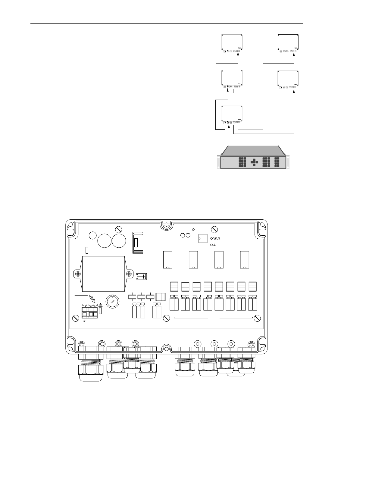
Using the BED-108/2 it is possible to change a
Daisy chain configuration to a Star configuration
or a combination of both.
BED-108/2 can also be used as a repeater or as a
booster for the Telemetry Receivers BDR-51X or
BDR-91X which are normally working up to 1200
m. Using the BED-108/2 transmission distance up
to 5000 m can be achieved.
Installation
Box Installation
The BED-108/2 should be mounted at a suitable location where mains is available.
The box should be mounted on a plane surface to avoid twisting of the box, resulting in
possible leakage.
PWR
X1X3
MAINS IN
X2
NL
MAINS
SELECT
F5
CC NC NO
Power Fail
Detect
ERNA
IN
- +
- +
1
Ih 140
265VAC
DANGER
ACHTUNG
230
1
1
5
S1
Ih 1100
F6
XA1 XB1
- +
ERNA OUT
- +- +
234
- +5- +6- +7- +
8
+10V
ON
0498-00053 V. 0.1
XG1XC1 XD1 XE1 XF1
H1H2
TP1
TP2
XH1
DATA
TP3
ERNITEC
BED-108/2 RS-485 Distribution
If the box is mounted on a concrete or similar surface, use rawlplugs and galvanised
roundhead 1" screws such as no. 8 (ø4.1 x 25 mm).
If the box is mounted on a wooden surface, use galvanised roundhead 3/4" screws no. 8
(ø4.1 x 19mm) or similar.
When mounted outside, the box should be fixed with the cable glands pointing down.
Installation Instructions BED-108/2
Page 2 3020-00041
POWER
500 series
500 series
500 series
500 series
BED-108
1200 m
5000 m
BDR-51X = 1200 m
BDR-55X = 5000 m
5000 m
5000 m
Page 3
Mains Installation
The BED-108/2 must be used with a 3-wire mains connection (2W+PE @ min. 0,75mm2).
Terminals marked with hazardous live symbol requires installation by an instructed person.
Details on the mains supply can also be found on a label fitted inside the lid of the
BED-108/2.
If permanently connected to mains, a readily accessible disconnect device shall be incorporated in the building installation wiring.
If pluggable connection to mains, the socket-outlet shall be installed near the equipment and
shall be easily accessible.
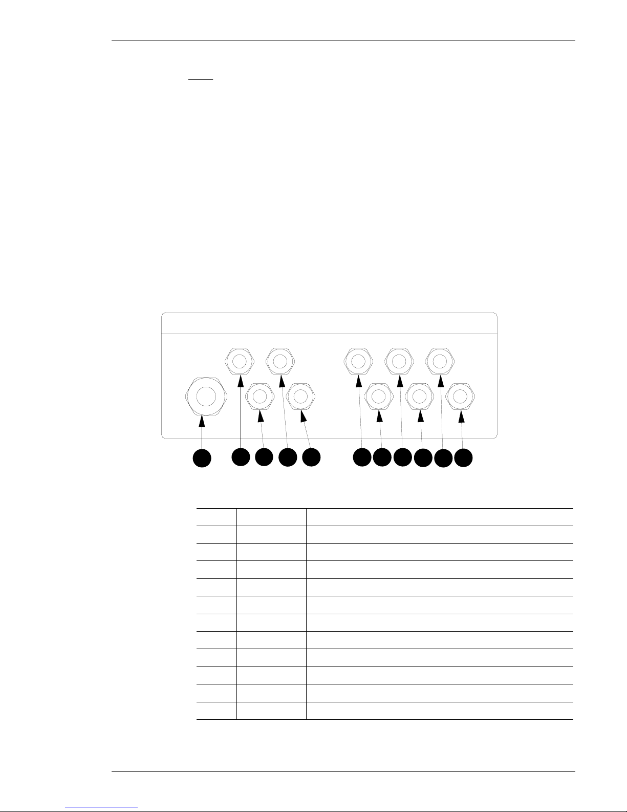
Cable connections
It is of utmost importance that all cable connections are carried out, exactly as described in
order to avoid malfunction or damage to the BED-108/2, or the connected equipment.
All cables to and from the BED-108/2 are fed through the cable glands. Choose an
appropriate size gland for the actual cable and tighten the glands when all cables are
connected.
The choice of cable is important to the optimal function of the BED-108/2.
01
02 03
04
06
07
08
09
10 11
05
Cable glands layout
The following table shows how the cable glands are intended to be used:
RS485 output cable 8PG 911
RS485 output cable 7PG 910
RS485 output cable 6PG 99
RS485 output cable 5PG 98
RS485 output cable 4PG 97
RS485 output cable 3PG 96
RS485 output cable 2PG 95
RS485 output cable 1PG 94
RS485 input cablePG 93
Power failure cablePG 92
Mains input cablePG 161
DescriptionSizeNo.
Installation Instructions BED-108/2
3020-00041 Page 3
Page 4

CE/Safety
All electronic equipment can emit or be sensitive to induced electromagnetic noise, which can
be conducted by the connected wires or transmitted as electromagnetic fields.
Electromagnetic noise can cause malfunction or damage to the equipment.
The BED-108/2 are tested to, and fulfils, the following EMC standards:
EN 50081-1 (Emission)
EN 50130-4 (Immunity)
These standards covers equipment installed in an industrial environment.
The BED-108/2 fulfil the following safety standard:
IEC 60950
BED-108/2 Layout
The BED-108/2 has been designed for easy installation and set-up. The below figure shows
the layout of the Simplex RS485 Distribution Unit.
PWR
X1X3
MAINS IN
X2
NL
MAINS
SELECT
F5
CC NC NO
Power Fail
Detect
ERNA
IN
- +
- +
1
Ih 140
265VAC
DANGER
ACHTUNG
230
1
1
5
S1
Ih 1100
F6
XA1 XB1
- +
ERNA OUT
- +- +
234
- +5- +6- +7- +
8
+10V
ON
0498-00053 V.0.1
XG1XC1 XD1 XE1 XF1
H1H2
TP1
TP2
XH1
DATA
TP3
ERNITEC
5 61
2
43
BED-108/2 Layout
8x RS485 outputs
6
RS485 input5
Mains failure connection4
Mains selection switch 115/230VAC3
Mains terminal block2
Safety Earth connection1
BED-108/2No.
Description
Installation Instructions BED-108/2
Page 4 3020-00041
Page 5

Mains connection
In order to fulfil the safety standard (IEC 60950), the mains cable must be routed via the
provided cable clip inside the BDR-510/2 box.
Mains terminal block
Cable clip
Mains cable
Mains cable
Mains cable clip
Connect the mains lead to the terminal block X2.
Make sure that the Mains Selection switch (S1) is set to match the local mains supply
(115VAC or 230VAC).
X1X3
MAINS IN
X2
NL
MAINS
SELECT
F5
CC NC NO
Power Fail
Detect
ERNA
IN
- +
- +
1
Ih 140
265VAC
DANGER
ACHTUNG
230
1
1
5
S1
XA1 XB1
- +
ERNA OUT
- +- +
234
- +5- +6- +7- +
8
XG1XC1 XD1 XE1 XF1 XH1
Mains - Live
Mains - Neutral (Blue)
Mains - Earth (Yellow/Green)
Mains selection switch
Mains connection
Make sure that each terminal is connected to the corresponding terminal of the mains outlet
(i.e. Phase to Phase, Neutral to Neutral and Earth to Earth). Otherwise malfunction or even
damage to the BED-108/2 will occur.
For specification of mains, refer to Specifications, at the end of these instructions.
RS485 (ERNA Camera control) input connection
The RS485 signal is connected to terminal X1.
It is important that the polarity of the connection is correct, otherwise it will not be possible
to obtain control.
Note, the RS485 input is galvanic separated from the rest of the circuit in order to avoid
ground loop problems, therefore:
DO NOT CONNECT THE SCREEN OF THE CABLE TO GROUND/EARTH!.
RS485 (ERNA Camera control) output connection
The RS485 output signal is connected to the terminals XA1 to XH1.
Power failure connection
If an alarm in connection with mains failure is necessary, the connection can be made to
terminal X3. Potential free contacts are provided for a normally open or normally closed
output.
Installation Instructions BED-108/2
3020-00041 Page 5
Page 6

Specifications
Kg1,2Weight
mm240 x 160 x 90Dimensions
ABS boxIP 65Enclosure
IEC 60950Safety
EN 50081-1
EN 50130-4
EMC/EMI
Non-condensing%95Relative humidity
ºC55-20Operating temperature range
mA30Current consumption (230VAC)
mA60Current consumption (115VAC)
Hz6045Mains frequency
115/230VAC
selectable
VAC253230207Mains input 230VAC
115/230VAC
selectable
VAC126115104Mains input 115VAC
General
using 0.6 mm solid
copper twisted
pair standard
telephone cable @
25 ºC
km5Transmission distance
Potential free
contacts
RelayPower failure
Ohm120Load impedance
V
pp
10ERNA, RS-422 or simplex RS-485 (8x)
Outputs
mA8Current consumption
Ohm132120108Impedance
V
pp
102ERNA, RS422 or simplex RS485
Inputs
NoteUnitMax.TypMin.ParameterDescription
Specifications
Installation Instructions BED-108/2
Page 6 3020-00041
Page 7

Drilling pattern for box (not to scale)
130,0 mm
228,0 mm
Installation Instructions BED-108/2
3020-00041 Page 7
HEAD OFFICE: ERNITEC A/S, HØRKÆR 24, P.O. BOX 720, DK-2730 HERLEV, DENMARK
TELEPHONE: +45 44 50 33 00, TELEFAX: +45 44 50 33 33
HOMEPAGE: http://www.ernitec.dk, E-MAIL: ernitec@ernitec.dk
UK OFFICE: ERNITEC UK, GERRARD HOUSE, WORTHING ROAD, EAST PRESTON, WEST SUSSEX BN16 1AW, ENGLAND
TELEPHONE: 01903 77 27 27, TELEFAX: 01903 77 27 07
E-MAIL: sally@ernitec-uk.co.uk
GERMAN OFFICE: ERNITEC GmbH., STORMARNRING 28, 22145 STAPELFELD, GERMANY
TELEPHONE: (040) 6756 25 0, TELEFAX: (040) 67 56 25 25
E-MAIL: ernitec@aol.com
FRENCH OFFICE: ERNITEC FRANCE, N° 29 PARC CLUB DU MILLENAIRE, 1025 RUE HENRI BECQUEREL, 34036 MONTPELLIER CEDEX 1, FRANCE
TELEPHONE: (4) 67 15 10 15, TELEFAX: (4) 67 64 01 81
E-MAIL: ernitec@ernitec.fr
MIDDLE EAST OFFICE: ERNITEC ME, HAMRA-MAKDESI STR., YOUNIS CENTER-5th FLOOR, OFFICE NO. 503
P.O. BOX 113/5721, BEIRUT, LEBANON TELEPHONE: +961 1 751 796, TELEFAX: +961 1 751 795
HOMEPAGE: http://www.ernitecme.com, E-MAIL: malek_kabrit@ernitecme.com
 Loading...