

Page 1
Twisted Pair Video Transmission
Series 230/3
Boxed versions
PWR
BVR 230-G
DANGER
MAINS IN
N L
ernitec
0498-00083 V.0.1
VIDEO IN
VIDEO OUT
SYNC
GND
BAS-
BAS+
MF-HF LF GAIN
J3
+
J1
1 3
+
~~
1 31 3
J2
ERNITEC DENMARK, HØRKÆR 24, DK-2730 HERLEV, DENMARK
PHONE. + 45 44 50 33 00, FAX: + 45 44 50 33 33, E-MAIL: info@ernitec.dk
ERNITEC UK, PHONE: + 44 (0) 1903 77 27 27, FAX: + 44 (0) 1903 77 27 07, E-MAIL: info@ernitec.co.uk
ERNITEC GERMANY, PHONE: + 49 (0) (40) 6756 25 0, FAX: + 49 (0) (40) 67 56 25 25, E-MAIL: info@ernitec.de
ERNITEC FRANCE, PHONE: + 33 (4) 67 15 10 15, FAX: + 33 (4) 67 64 01 81, E-MAIL: info@ernitec.fr
www.ernitec.com
2800-00087
Page 2

Introduction
The following units are covered in this manual:
Boxed video transmitter BVT-230.
Boxed video receiver BVR-230-1GV/3.
Boxed video repeater BVX-230-1GV/3.
All three units are fully compatible with other Ernitec twisted pair video equipment.
However, the specified transmission distance, and adjustments, assumes the use of
Series 230 equipment only.
Throughout theses instructions, reference is made to the drawings which can be found in
the back of these instructions.
General
The Series 230 Twisted Pair Video Transmission equipment, is designed for use with
standard CAT5e twisted pair cable. It can also be used with standard 120 ohm twisted pair
cable, suited for video transmission. Types like the Belden 1872A or 1700A, can also be
used.
On the receivers, and repeater, the twisted pair input is galvanically separated to avoid
earth loop problems (hum bars).
All boxed types are housed in an IP65 rated enclosure.
The Boxed Series 230 types are mains supplied - 230VAC, but can also be ordered in
115VAC versions.
Coax and twisted pair cables, can be connected/disconnected with power on.
Box Installation
Choose a plane surface to prevent the box from being twisted and thereby becoming
leaky when mounted. When mounted outdoor the box should be installed with the cable
glands downwards.
Screws and wall plugs are supplied in the mounting kit. Drilling dimensions are shown in
the back of this manual.
2800-00087
Page 3
Mains Installation
Terminals marked with hazardous live symbol requires installation by an instructed
person.
The BVT/R/X-230 must be used with a 3-wire mains connection (2W+PE @ min.
0,75mm2).
If permanently connected to mains, a readily accessible disconnect device shall be
incorporated in the building installation wiring.
If pluggable connection to mains, the socket-outlet shall be installed near the equipment
and shall be easily accessible.
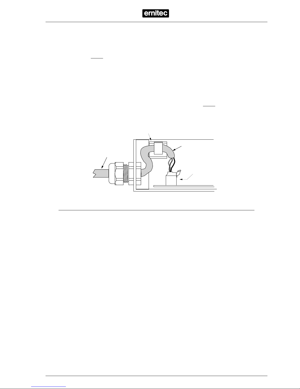
In order to fulfil the safety standard (EN60950), the mains cable must be routed via the
provided cable clip inside the Series 230 box. The figure below shows how the mains
cable should be routed.
Mains terminal block
Cable clip
Mains cable
Mains cable
WARNING: Make sure the equipment is earthed; otherwise the over
voltage protection will not work! Although both the transmitter and the
receiver are earthed no hum bar problems will occur due to the galvanic
separation of the video signal in the receiver.
Cable Connections
Please refer to the drawings in the back, for details on cable connections.
At the receiver end, do not in any way connect the twisted pair shield. If the shield is
connected to the receiver, the galvanic separation will not work!
The shield should be connected at the transmitter end only.
2800-00087
Page 4

Adjustment
For optimum performance, under all lighting conditions, it is highly recommended to use a
Grey scale/Multiburst Video Generator, and an Oscilloscope for the adjustment.
Especially when using digital video equipment - like DVR’s - it is important to adjust for
best possible video performance.
1. Connect the Video Generator to the camera input of the BVT-230, and select the
Grey scale/Multiburst signal. Output must be 1Vpp. It is not mandatory to have a
colour signal.
2. Set the links on the BVT-230, according to cable length and type.
3. Connect an Oscilloscope and monitor, to the video output of the BVR-230-1GV (or
local monitor output on the BVX-230-1GV/3). To connect both Oscilloscope and
monitor to the receiver, use a BNC T-connector, or the loop output of the monitor.
Remember to set the monitor termination to 75 ohm.
4. If a negative, or turned over, picture is displayed, swap the +/- twisted pair input on
the receiver.
5. Check that the green SYNC LED on the receiver is flashing, indicating that a valid
video signal is received.
6. On the receiver, turn pots RV1, RV2 and RV3 fully counter clockwise.
7. Adjust RV1 (Gain) to an output of 1Vpp.
8. Adjust RV3 (LF) to get the sync pulse as well defined as possible.
9. Adjust RV2 (MF/HF) to get as much MF/HF signal (max. 0,7Vpp) as possible.
10. Readjust RV3 and RV2 to get the signal as identical as possible to the original
signal, see drawing below.
11. Readjust RV1 to exactly 1Vpp.
12. Check that the picture looks OK on the monitor.
Please note that adjustments RV2 and RV3 has a certain overlap, and will influence on
each other. The trick is to fine tune both for optimum signal.
Grey Scale/Multiburst Signal
Sync pulse (RV3)
Gray Scale (RV3)
Multiburst (RV2)
1 Vpp (RV1)
0,7 Vpp (RV2/RV1)
2800-00087
Page 5

Twisted Pair Cable Specifications
The cables are the most important part of a Twisted Pair Video installation, and the overall
performance and transmission distance, depends on the selected twisted pair cable.
Please note, that twisted pair cables with stranded conductors are NOT suitable the conductors must be solid.
When shielded cables are used the transmission distance might be considerably lowered,
due to the higher capacitance introduced by the shield - carefully study the specification
on the actual cable and compare them with the table below. The choice between shielded
and unshielded cable will always be a compromise between transmission distance and
immunity towards noise and crosstalk.
pcs./m5Twists
dB/km30-36Attenuation @ approx. 5 MHz
nF/km90Capacitance
Ω
130120100Characteristic impedance @ <1 MHz
mm10,6-0,80,5Solid conductors, diameter (ø)
UnitMax.Typ.Min.Description
Suitable cable types:
Standard Category 5e.
Belden 1700A.
Belden 1872A.
Mödinger A-2Y(L)2Y / 2x2x0,6 (2 pairs).
Note: When using cables including several not individually screened pairs, it is, as a
general rule, not recommended to use more than one pair per cable, in order to avoid
possible crosstalk.
Note: When using cables including several not individually screened pairs, do not mix long
and short cable distances, in order to avoid possible crosstalk.
Note: Avoid locating unscreened twisted pair cables parallel to high speed data cables,
mains cables, or other cables with high energy and/or high frequency signals.
EMC/EMI
All electronic equipment can emit, or be sensitive to, induced electromagnetic noise which
can be conducted by the connected wires, or transmitted as electromagnetic fields.
Electromagnetic noise can cause malfunction or damage to the equipment.
The Series 230 fulfils the relevant EMC standard (refer to specifications) and is therefore
CE labelled.
WARNING: The stated approvals, and other specifications are valid only if
the equipment is installed according to the instructions in this manual.
2800-00087
Page 6

Specifications
EN60950Safety
Immunity: EN50130-4, Emission: EN6000-6-3EMC/EMI
Approvals
IP 65Protection
kg0,8Weight
excl. cable glandsmm60145220Dimensions, L x W x
H
Enclosure
@ 86-106 KPa%85Humidity
o
C50- 25Temperature
Environment
@ 115VACmA
BVX
Max. 90
BVR
Max. 60
BVT
Max. 50
@ 230VACmA
BVX
Max. 45
BVR
Max. 30
BVT
Max. 25
Power consumption
45-60HzVAC126115104115VAC (optional)
45-60 HzVAC253230207230VAC
Power supply
Common Specifications
dB50CMMR
WeighteddB66Signal/noise ratio
+/- 2dBHz10 M25Frequency response
Unbalanced 75 Ω
Vpp1,210,8Voltage, adjustable
Unbalanced video
outputs
@ 5MHzdB70Equalisation
Balanced 110
Ω
Vpp2 Voltage
Video Input
BVR-230-1GV/3 & BVX-230-1GV/3 (receiver part)
dB36CMMR
WeighteddB66Signal/noise ratio
@ 5 MHzdB630Equalisation
+/-
2dB
Hz10 M25Frequency response
Balanced 110
Ω
Vpp42Voltage
Video Output
@1Vpp in
BVT-230 & BVX-230-1GV/3 (transmitter part)
Unbalanced 75 Ω
Vpp1,51Voltage
Video Input
CommentsUnitMax.Typ.Min.
BVT-230
Transmission distances
CAT5E 0.5mm: 1700 m.
Mödinger A-2Y(L)2Y 0,6mm: 2200 m.
To obtain the above distances, it is important that the correct type of cable is used, and
that the cable is an uninterrupted run, without the use of junctions and cross-fields.
It is also required to use a Video Pattern Generator and Oscilloscope for the adjustment.
When using BVX-230-1GV to extend the distance, it is not recommended to use more
than two BVX-230-1GV, giving a total distance of 5100/6600 m. At these distance, a
certian decrease in performance, must be expected.
2800-00087
Page 7

Up to 2200 meters twisted pair cable
Local monitor(s)
(optional)
Shield:
DO NOT
CONNECT!
BVX-230-1GV/3
188,3 mmDrilling dimensions:
Up to 2200 meters twisted pair cable
BVT-230
BVR-230
2 Vpp
3 Vpp
+3 dB @5MHz
4 Vpp
+6 dB @5MHz
<600 m
<900 m >900 m
P1: Bal. output voltage
CAT5E 24AWG (0.5mm)
2 Vpp
3 Vpp
+3 dB @5MHz
4 Vpp
+6 dB @5MHz
<1000 m <1500 m
>1500 m
P1: Bal. output voltage
TWP 120 ohm (0.6mm)
90 mm
-
+
-
+
Shield
J5
J4
230VAC
max. 45mA
45-60Hz
J3 J2
J2
VIDEO OUT
VIDEO INVIDEO OUT
MAINS IN
J6: Remove if used with
PVT-100 Transmitter
J6
Page 8

Neutral
(blue)
Earth
(yellow/green)
230VAC
max. 30mA
45-60Hz
Shield
RV2
(MF/HF)
RV3
(LF)
1 Vpp
RV1
(gain)
BVR-230-1GV/3
Up to 2200 meters twisted pair cable
90 mm
188,3 mm
BVT-230
Drilling dimensions:
Shield:
DO NOT CONNECT!
-
+
MAINS
N
IN
L
DANGER
0498-00082 V0,10498-00082 V0,1
BVT230BVT230
ernitecernitec
PWR
OUT
VIDEO
VIDEO
IN
J3
+
+
J1
J2
- +BAS
POS 2-3 -> 4Vpp
POS 1-2 -> 3Vpp
OPEN 2Vpp
P1
230VAC
max. 25mA
45-60Hz
2 Vpp
3 Vpp
+3 dB @5MHz
4 Vpp
+6 dB @5MHz
<600 m <900 m
>900 m
P1: Bal. output voltage
CAT5E 24AWG (0.5mm)
2 Vpp
3 Vpp
+3 dB @5MHz
4 Vpp
+6 dB @5MHz
<1000 m
<1500 m >1500 m
P1: Bal. output voltage
TWP 120 ohm (0.6mm)
Live (black,
brown, red)
- +
J3
J2
J1
J4
J4: Remove if used with
PVT-100 Transmitter
 Loading...