

Page 1

3www.ERNI.com/contact/
catalog E 074484 05/02 Edition 4
General information
The DIN 41612/IEC 60603-2 connector family consists of 13
basic sizes and many complementary versions.
It was developed for use in 19" rack systems in accordance
with DIN 41494. The large number of different sizes and the
efficient connection techniques have made it possible to install
these connectors for an extremely wide range of applications.
Typical areas of application:
• Connection between plug-in card and back-panel wiring
• Connection between two PCB’s arranged one above the
other
• Connection to peripheral equipment with connector
housings as accessories
• As periphery connectors for external interfaces from the
wiring side
Main features
• Two piece printed circuit board connectors
• International approvals, such as UL or CSA
• 13 connector sizes with the same plugin and mounting
conditions
• Additional connector sizes complementing the
DIN 41612/IEC 60603-2
• Different coding available
• Up to 160 pins/contacts
• Two to five row connectors possible
• Various termination types available
• 2.54 mm (1/10") basic pitch
• Early make/last break contacts available on request
• Wide range of accessories
• Complete interface system available
• All female connectors montioned in this data sheet have
dual sided female contact spring.
This contact principle even offers a max. security in contacting
and remaining contact resistence in extreme situations.
Early make/last break
For the connectors size B, C, Q, R, D, E and F 0,8 mm early
make/last break male contacts can be loaded in any position
in rows a, b, c, d, e and z.
The early make/last break of the high current connectors size
H11 and H15 have a length of 3,5 mm (1,5 mm on request).
Other lengths of early make/last break contacts on request.
Approval certificates
UL All male and female connectors of this data sheet
are approved by the American approvals authority
„Underwriters Laboratories Inc.“ File Nr. E 84703.
CSA For all our male and female connectors we have the
recognition of the „Canadian Standard Association“
under the File Nr. LR 62504.
Pre-centering
For applications with early make/last break contacts the male
connector insulators with pre-centering ensures even more
reliable mating.
The insulators of the female connectors have a recess at an
appropriate point. The dimensions of these versions do not
conform to the specifications of DIN 41612/IEC 60603-2. The
ordering details are not listed in this data sheet but they can
be supplied on request.
Male connectors with pre-centering do not fit female
connectors without a pre-centering recess.
Connectors DIN 41612/IEC 60603-2
and completions
Page 2

5www.ERNI.com/contact/
catalog E 074484 05/02 Edition 4
Type BCDEF H
Reversed Type QR
Max. number of contacts 64 96 32 48 48 11 15
Contract row designation of
male and female connectors ab abc ac ace zbd b zd
Temperature range - 65° . . . + 125°C
Permissible humidity Annual average ≤ 80%, max. 100%
Cr 1.8 1.8 6.0 8.0
Cl 1.6 1.6 3.5 4.5
Cr 1.2 3.0 3.0 8.0
Cl 1.2 3.0 1.6 4.5
Cr 1.2 3.0 3.0 8.0
Cl 1.2 3.0 3.0 (1.6)* 1.6 4.5
Current A
rating at +20°C (293K) 4.0 5.5 20.0
ambient +70°C (343K) 2.0 4.0 15.0
temperature +100°C (373K) 1.0 2.5 10.0
Test voltage, 50Hz, 1min
Contact/contact Vrms 1000 1550 1550 3100
Contact/ground Vrms 1550 1550 2500 3100
Contact resistance mΩ≤20 ≤ 15 ≤ 8
Insulation resistance Ω≥10
12
at 100 VDC
Shock and vibration no contact breakdown
proofness at 20g and 10...2000Hz
Housing material of male PBT 30 % GV
and female connectors PC 30 % GV
Comparative
creepagefigure PBT CTI 275 / CTI 175 M
to DIN IEC 112 PC CTI 150-175 / CTI 100 M
Service life to Performance level 1 ≥ 500 Mating-cycles
DIN 41 612, Part 5 Performance level 2 ≥ 400 Mating-cycles
Mating and withdrawal 64pin.60 96pin.90 32pin.40 48pin.60 48pin.75 15pin.90
force for the assembled 64pin.60 32pin.40 32pin.50 11pin.80
connectors N 32pin.30
Withdrawal force per contact ≥ 0.15 ≥ 0.2
(test blade) N
Inflammability PBT Polybutylenterephthalat non flammable as per UL 94 V-0
of the plastic PC Polycarbonat non flammable as per UL 94 V-1
* The type E male connector terminations are either available with a 5.08 mm or a 2.54 mm grid.
The technical data for the 7 high-voltage contacts correspond to size H15, where as the 24 signal contacts are identical to type F.
Contact
to
ground
Contact to
contact
within a row
between
a row
Creepage
(Cr)
and
clearance
(Cl)
in mm
Page 3

6 www.ERNI.com/contact/
catalog E 074484 05/02 Edition 4
Terminatinon technics
Connectors with termination techniques ERNIPRESS and IDC can be found in the corresponding data sheets.
Performance level
107 Conforms to the requirements as per
DIN 41612/IEC 60603-2
performance level 1
500 mating cyles
Contact zone gold-plated
Terminal zone tin-plated
101 Same as for version 107 but terminal zone gold-plated
207 Conforms to the requirements as per
DIN 41612/IEC 60603-2
performance level 2
400 mating cyles
Contact zone gold-plated
Terminal zone tin-plated
201 Same as for version 207 but terminal zone gold-plated
Example of how to order
Page 4

19www.ERNI.com/contact/
catalog E 074484 05/02 Edition 4
inverse size as per DIN 41612/IEC 60603-2
Size R
Dimensional drawings
Male connector
Female connector
Page 5

20 www.ERNI.com/contact/
catalog E 074484 05/02 Edition 4
Orderings details
Male connector size R
as per DIN 41612/IEC 60603-2, maximum three rows loaded, maximum 96 contacts
304 221 304 421
334 211 334 411
304 225 304 425
334 215 334 415
334 210 334 410
334 214 334 414
043 331
033 592
The connectors of the size R can be coded also with coding
wedges. The coding positions on the male connectors are
removed with a special pair of pliers. On the pertirent positions
on the female connectors coding wedges are inserted.
Further versions on request.
Male connectors with early make/last break contacts can be
loaded in any position.
Page 6

21www.ERNI.com/contact/
catalog E 074484 05/02 Edition 4
Orderings details
Female connector size R
as per DIN 41612/IEC 60603-2, maximum three rows loaded, maximum 96 contacts
023 039
004 519
023 503
004 516
023 784
For applications with size R female and size C male
connectors we provide the reverse female connector with
mirror-inverted printing. Please contact the ERNI sales office
for further information.
Further versions on request.
Page 7

39www.ERNI.com/contact/
catalog E 074484 05/02 Edition 4
Mounting hole pattern, PCB
Male – and female connectors
as per DIN 41612/IEC 60603-2, right angle terminations, view of equipment side
1) Hole pattern for right angled male and reverse
female connectors as per DIN 41612/IEC 60603-2
2) Hole pattern for right angled female connectors
(adapter connector) modified as per DIN 41612/IEC 60603-2
Page 8

40 www.ERNI.com/contact/
catalog E 074484 05/02 Edition 4
Mounting hole pattern, PCB
Male – and female connectors
as per DIN 41612/IEC 60603-2, right angle terminations, view of equipment side
Female size B
Female size C
Male size Q
Male size R
Female size D Female size E Female size F
For the sizes B and Q the rows a and b are required only.
remaining dimensions
as per hole pattern 1
remaining dimensions
as per hole pattern 1
remaining dimensions
as per hole pattern 1
Hole pattern 1
Page 9

42 www.ERNI.com/contact/
catalog E 074484 05/02 Edition 4
Common dimensions for all sizes of the connector family
as per DIN 41612/IEC 60603-2
Important dimensions
Page 10
43www.ERNI.com/contact/
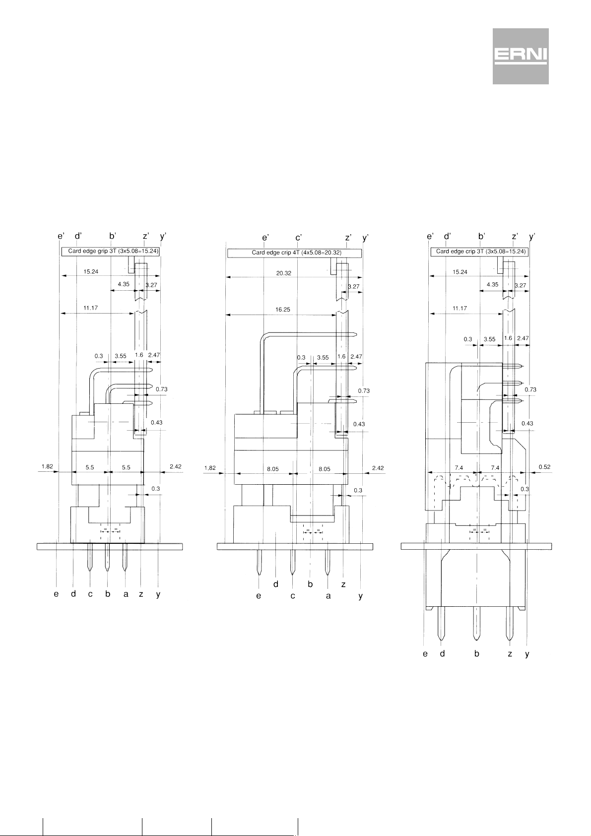
catalog E 074484 05/02 Edition 4
Mounting dimensions of the connectors
in the module spacing of the 19" rack system
Exact position of the connectors
in the size C module spacing
Exact position of the connectors
in the size E module spacing
Exact position of the connectors
in the size F module spacing
These drawings contain important dimensions for the use of
DIN 41612/IEC 60603-2 connectors in 19" rack systems.
The mounting dimensions shown for size F connectors
illustrates how the width of 3 x 5.08 mm is maintained by
means of the pitch offset between mating side and soldering
side. Thus size F connectors can still be mounted in the
3 x 5.08 mm module.
 Loading...