

Page 1

ERMO 482-200 Microwave Sensor
Description of Operation
Introduction
The ERMO 482-200 microwave sensor is a field disturbance sensor “that establishes a
RF field in its vicinity and detects changes in that field from the movement of persons or
objects within its range” (47 CFR Part 15 §15.3(l)). The sensor is comprised of two
separate components: a transmitter and a receiver each housed in their respective, yet
visually identical, radomes.
Functionality
When properly installed, according to the Installation Guide, the sensor can cover
distances from between 50 and 200 meters (165 – 655 feet) in length. When a person or
an object with sufficient cross section passes between the transmitter and receiver, the
receiver alarm relay contacts are activated. Tamper contacts in the transmitter and
receiver are activated with the removal of the antenna radomes.
Transmitter Description
The transmitter is powered by 19 Vac which is rectified and regulated to simultaneously
charge a 12 Vdc sealed lead acid battery and power the remaining transmitter circuitry.
A further 9 Vdc linear regulator is employed to isolate the transmitter operation from
variations in supply voltage levels. A LM555 timer is configured as an astable
multivibrator with four user selectable operating frequencies (3, 5, 7 & 11 kHz with 50%
duty cycles) to permit the operation of multiple co-located units by digitally modulating
the carrier frequency of 10.525 GHz.
There are no user controls that vary the output level or carrier frequency.
Receiver Description
The receiver is powered by 19 Vac which is rectified and regulated to simultaneously
charge a 12 Vdc sealed lead acid battery and power the remaining receiver circuitry. A
further 5 Vdc linear regulator is employed to isolate the receiver operation from
variations in supply voltage levels. The received signal is amplified, filtered and the
modulation frequency recovered through the use of a LM567 Tone Decoder, which is
configured by the user to the same modulation as set on the corresponding transmitter (3,
5, 7, & 11 kHz). The user also adjusts the integration time and sensitivity (threshold) for
the desired level of operation.
Page 2
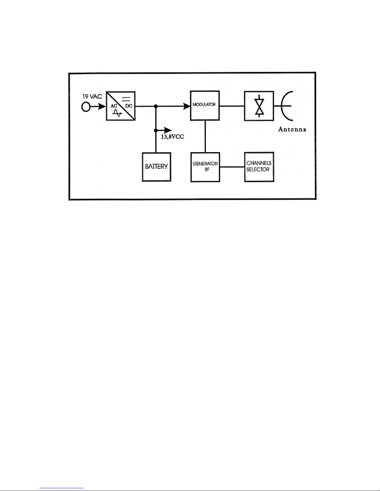
Microwave Transmitter Block Diagram: Transmitter Carrier Frequency 10.525 GHz
Modulation Frequencies 3, 5, 7, & 11 kHz
Page 3
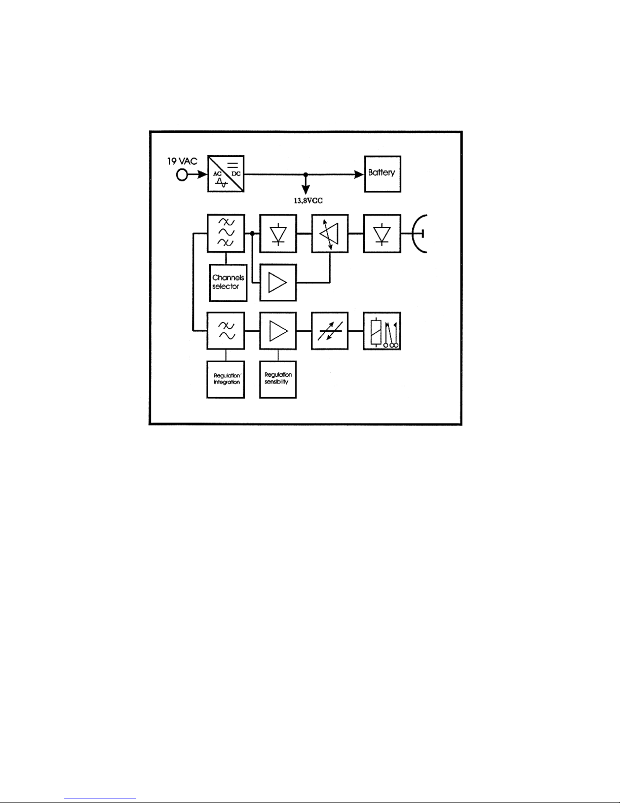
Microwave Receiver Block Diagram: Tone Decoder Frequencies 3, 5, 7 & 11 kHz
 Loading...