

erlab Captair Smart 321, Captair Smart 391, Captair Smart 483, Captair Smart 392, Captair Smart 481 User Manual
...Page 1
Safer
Simpler
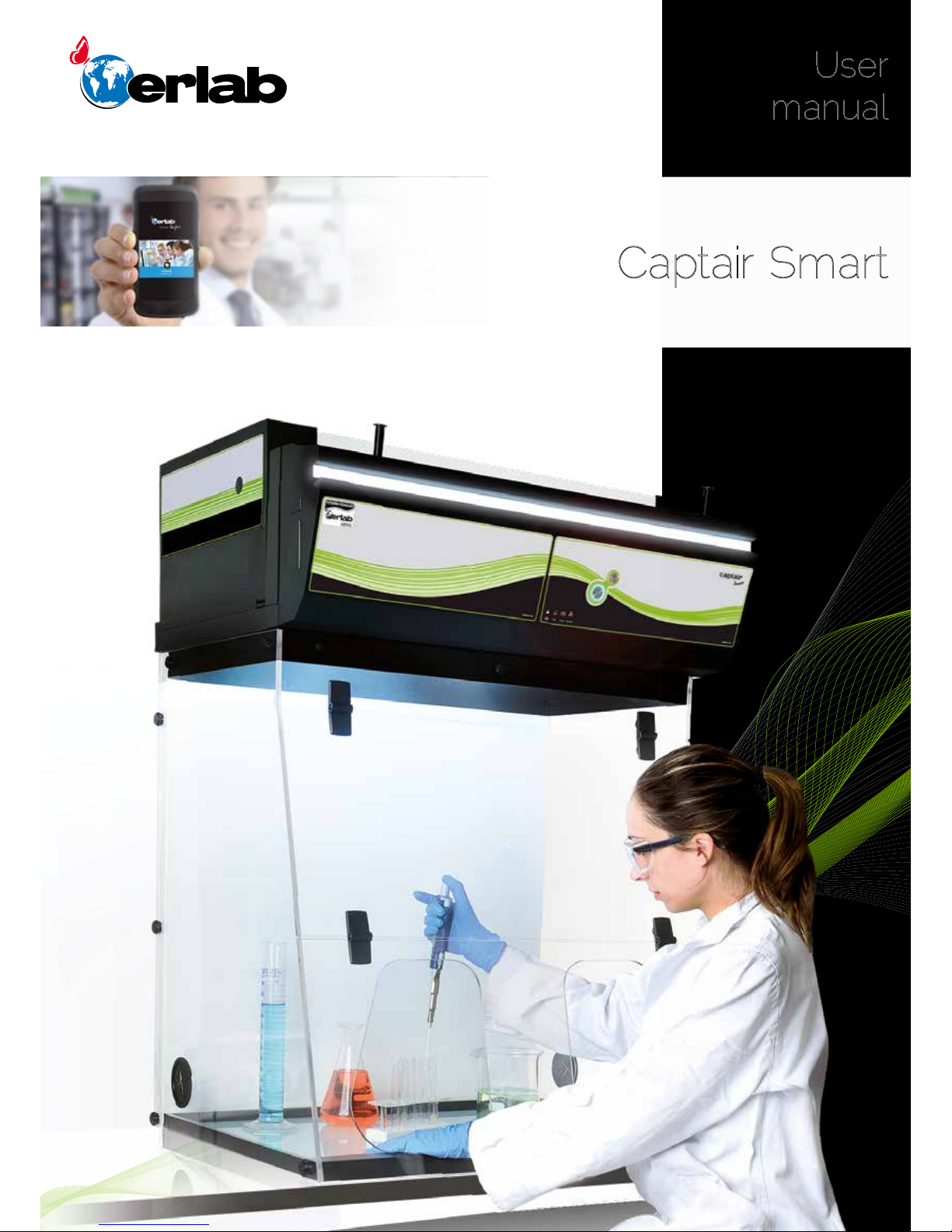
Captair Smart
Ductless filtering fume hoods
User
manual
Page 2

2
Captair Smart
General ....................................................................................................................................3
Safety notices ................................................................................................................. 3
Product registration ..............................................................................................4
Start-up ...................................................................................................................................5
- Calibrating the electronic anemometer
- Default settings
- Description of the control module
- Description of the alarms
e-Guard App.....................................................................................................................9
- Connectivity principle
- Options of connection
- Accessing the Administrator interface
- Administrator interface description
Fan setpoints ....................................................................................................................20
Procedure for automatic detection for the saturation
of a molecular filter using acetone ......................................................21
- Saturation detection using colorimetric tubes ...................................................21
- Saturation detection using PID Device ..................................................................23
- Saturation detection using Molecode S sensor .................................................25
Replacing the filters .................................................................................................27
Recommendations for storing
and using the filters .................................................................................................. 36
Replacement frequency for filtration breakthrough
sensor (Molecode option) ................................................................................. 37
Admissible weighs on working surfaces ........................................37
Cleaning and maintenance .............................................................................38
Contents
Page 3

3
User Manual
General
By choosing Captair Smart ductless ltration fume hoods, you have chosen an efcient and responsible way to
ensure safety.
Erlab’s 45 years of expertise in the eld of laboratory fume hoods provide unparalleled ltration quality to ensure your
users are properly protected when handling chemicals in the laboratory. The new Captair Smart range uses an innovative
and straightforward mode of communication called Smart technology. This powerful interface uses light to intuitively and
effortlessly communicate with users and leave them free to focus all their attention on the main task: handling the chemicals.
Your ductless Captair Smart ltration fume hood guarantees that you are protected when working with chemicals that pose
an inhalation risk. The Erlab ltration technology it employs traps hazardous particles and molecules and returns clean air
back into the laboratory.
The system’s connectivity allows for real-time safety alerts and individual device usage reports to be sent via the e-Guard
App.
Safety notices
The effectiveness of your device is directly dependent upon it being used correctly and monitored by its users. Your
laboratory may also benet from ergonomic, economic and ecological advantages provided by the Captair Smart fume hood
throughout its life cycle.
The E.S.P. program (Erlab Safety Program) was set up to guarantee your safety. We would remind you that it is important
to have the safety parameters validated before using the device for the rst time and whenever it is used for a different
application.
The handling of substances that are carcinogenic, mutagenic or toxic for reproduction (CMRs) underneath a fume hood is
covered by the French Labour Code. The code notably species that an in-depth risk analysis must be carried out prior to
any CMRs being handled under a recirculating fume hood.
The equipment provided is not intended to be used in an explosive atmosphere.
The lters delivered with this device must be removed from their packaging and positioned correctly; they must also be
suitable for the type of chemicals being handled in order to guarantee user safety.
Erlab recommends that lter breakthrough tests are regularly carried out.
Erlab recommends that the electronic anemometer is calibrated at least once a year.
The quantities of the chemicals handled in the enclosure should not be greater than those listed in the guide to approved
chemicals (the Chemical Listing).
AFNOR standard NF X 15-211: 2009 only applies to chemicals subject to an OEL.
Pursuant to the NF X 15-211 standard, only operations that can immediately be stopped are allowed to be carried out in a
Class 2 enclosure. Moreover, the fume hood’s lter must be replaced if any chemicals are detected downstream of the lter.
New lters must be stored in their packaging, kept in a dry location and laid at. (see recommendations for storing and using
the lters).
Erlab recommends keeping a logbook which is specic to the device and shows the chemical agents handled, how often
they are used and the maintenance operations carried out on it.
Page 4

4
Captair Smart
Product registration
Take full advantage of the device’s connectivity to enhance your safety
Get up to 10 years warranty on your connected Erlab unit
Register your product online: the registration of the product will automatically give you one extra year of warranty (in addition
to the warranty mentioned in the Erlab’ general terms and conditions of sale).
Connect your unit: Once the device is connected to the Internet and congured to exchange usage data, the warranty is
extended for up to 10 years. Warranty will be successively renewed at each lters replacement and for the life time indicated
on the Valipass® and/or or at the end of lter usage time.
In order to benet from Erlab extension of warranty offer, the following conditions shall be respected:
Warranty applicability is subject to the respect of the Erlab’ general terms and conditions of sale and following requirements:
• The registration and/or the connection of the product shall be performed within the twelve months from the purchase date ;
• Filters replacement must be performed following Valiquest® service recommendations or at the end of lter usage time ;
The lter’s serial number, used as an identication key, validates this condition, regardless of your device’s supplier
(and/or the replacement lter’s supplier for the following years);
• The device’s replacement lters must be manufactured by Erlab, as must all other spare parts.
Consumables such as lters and saturation sensors are not covered under warranty.
Page 5
5
User Manual
Start up
Calibrating the electronic anemometer
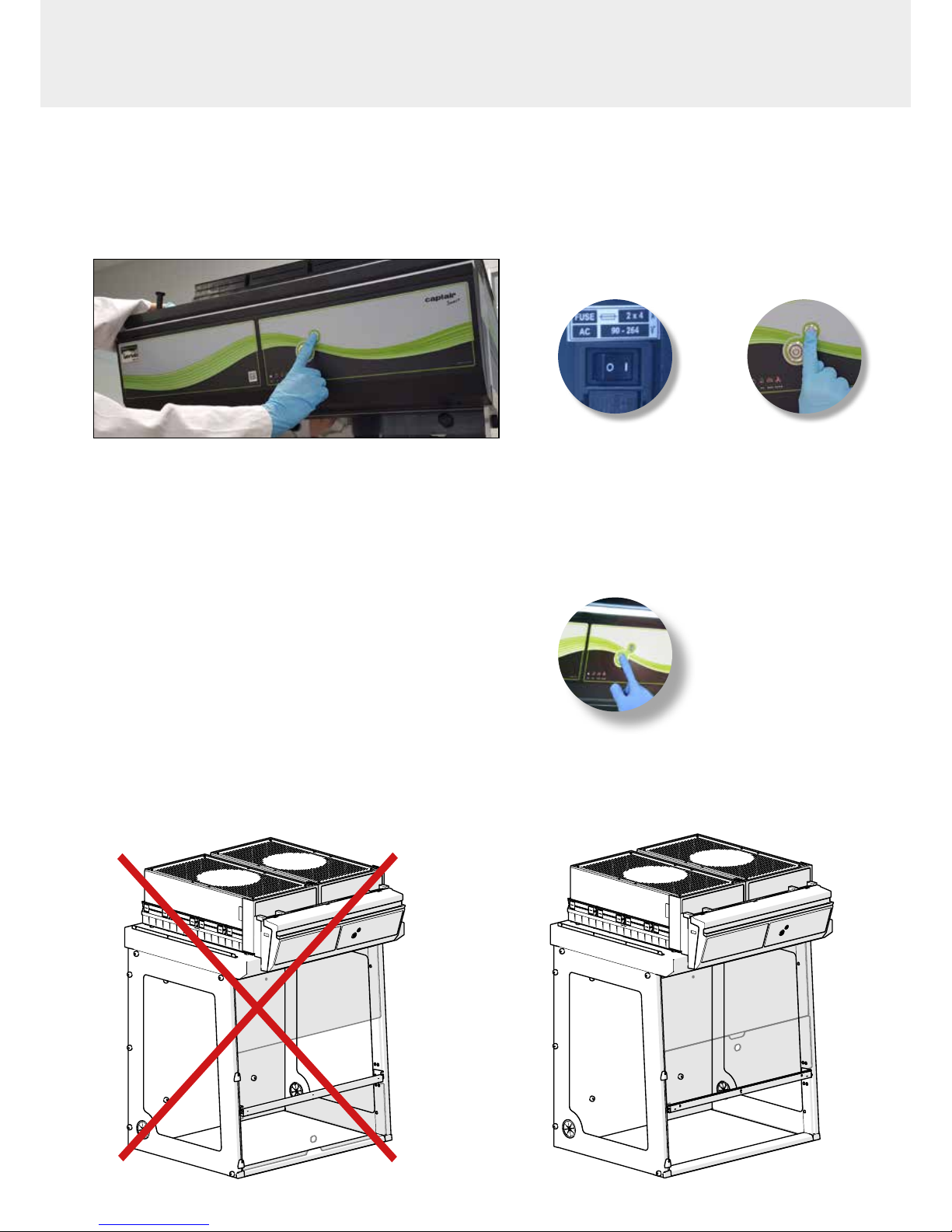
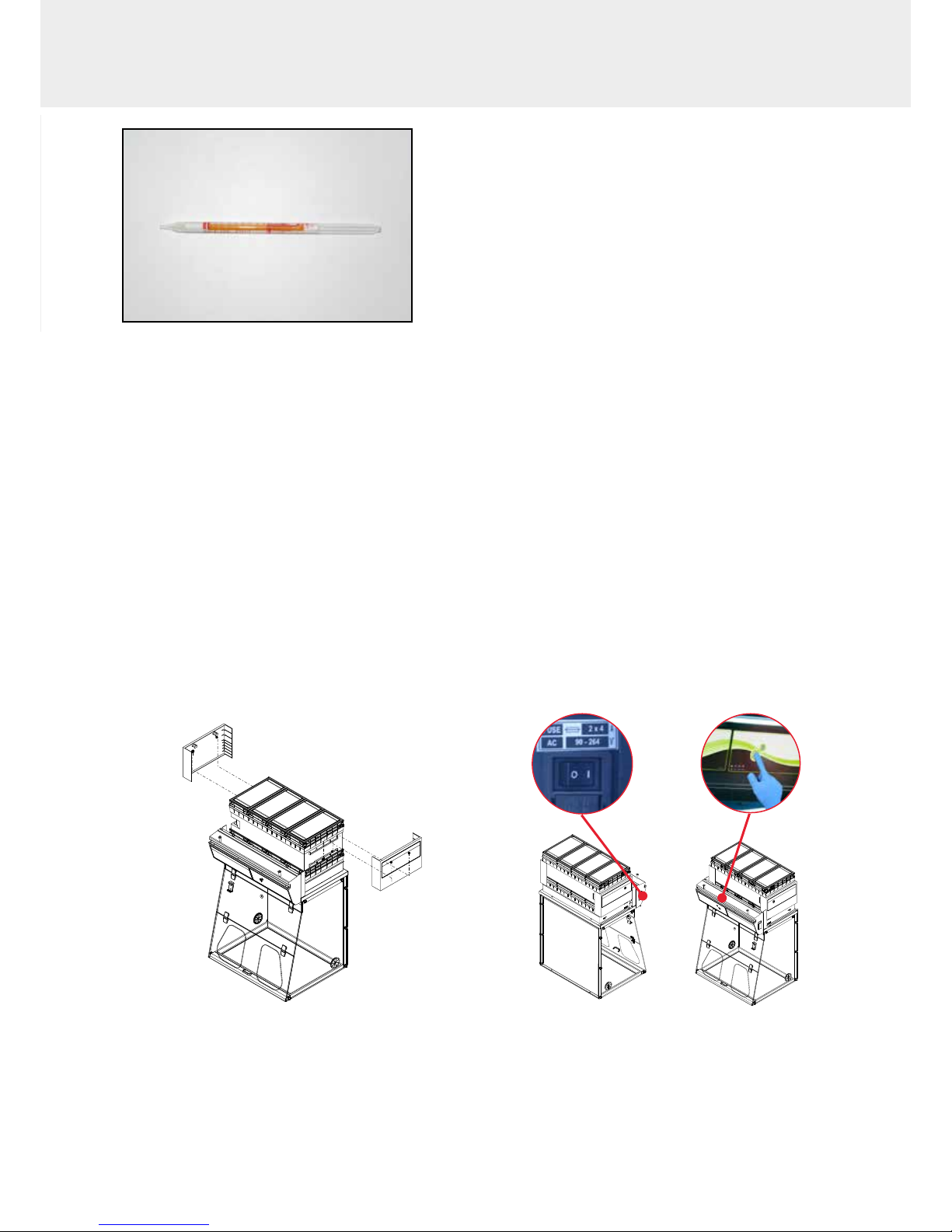
1- Press silmutaneously the main switch while switching on the main swith on the back of the control panel (off:O, ON:I)
2- Release immediately the mute button. A beep will proove the unit has started the calibration mode. LEDS lights will blink
fastly without any sound during 5min. 30 sec. LEDs lights blinking is different when an alarm is triggered.
3- Light blinking stops. The anemometer is calibrated and the unit is operational.
4- Turn on fan of the unit on the control panel.
5- Green light and LEDs lights are lighting.
Good practices :
- If you are using prelters, please be sure they are correctly located
- If you are using Reverso sash (Captair Smart 392 or 483 or 633 or 714 ductless fume hoods), please do the calibration as
indicated.
Main general switch Mute button
Press it silmutaneously
Page 6

6
Captair Smart
Having carefully followed the steps described in the installation guide, your Captair Smart
fume hood is now ready to use.
The power switch is located at the back of the control panel
Note: we recommend never turning off the main device power switch after the machine as
been started for the rst time.
The button on the control panel turns on the fan and the lights.
The green indicator light and LED light system should come on.
We also recommend verifying the operating parameters before each new use.
Filter breakthrough sensor (Molecode option) :
Default settings when the sensor has not been set in our factory:
- Solvents (S type): medium
- Acids (A type): medium
- Formaldehyde (F type): medium
To modify settings, please access the administrator interface.
Page 7
7
User Manual
Description of the control module
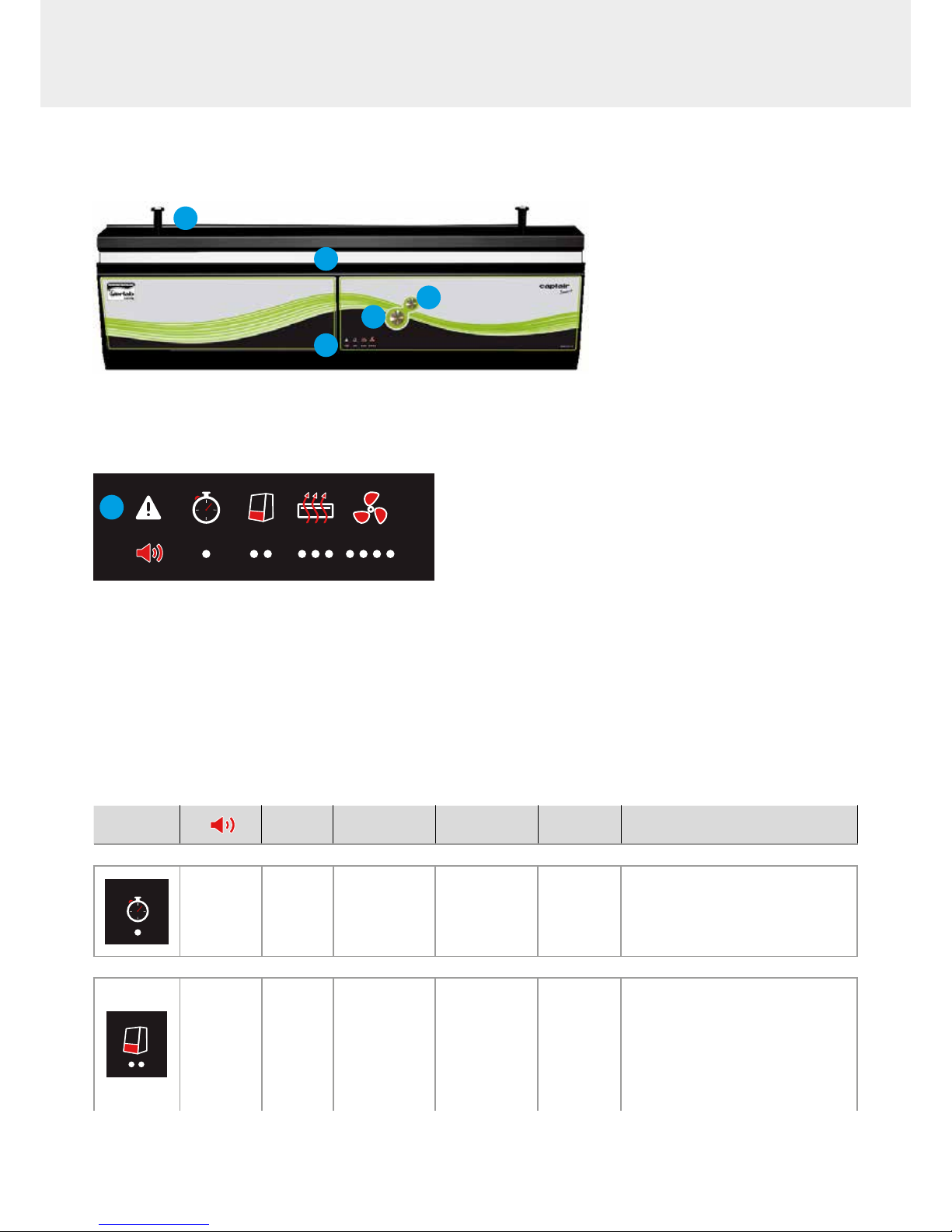
2
3
4
5
1
1 - Switch on fan and lights in hood
2 - Silence the alarm (Mute key)
3 - Keycode to indicate which alarm is active
4 - Smart-Light that pulses when in alarm
5 - Pegs to hold the sash fully open
Smart Technology gives you an easily identiable method of
communication about the containment, performance, and lter
efciency of your product via a soft, LED band of light called SmartLight - a light signature across the fascia which casts a stable LED
glow ensuring proper operation. If normal operation is disrupted,
the reassuring LED signature simply pulses, drawing the attention
of the operator only when necessary.
3
Description of the alarms
Note:
When using the Mute key to silence the alarm, please note the alarm can be triggered again if the event condition has not been xed.
Resetting alarms via the Mute key will consequently modify usage settings.
Please access the administrator interface to precisely check user settings.
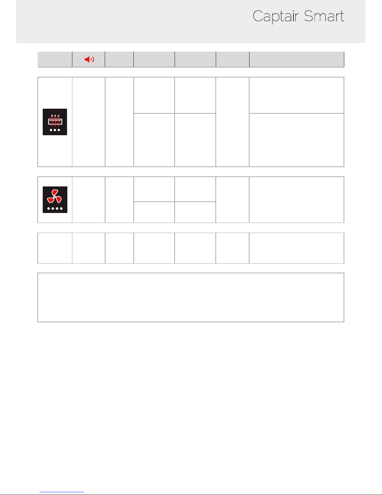
Alarm type
Light
signal
Events Details
Silence
the alarm
Reset the alarm
Timer
1 beep
5 seconds
apart
Pulses
Operating time
elapsed
timer (60 hours
according to the
NFX 15-211
standard)
The operating
time specied
in the timer
settings has run
out.
Press Mute
key
Pressing the Mute key will reset the Timer.
Note: the Timer can be set by accessing
the administrator interface.
Air speed
2 beeps
5 seconds
apart
Pulses Low air speed
The air speed
value is <0.4 m/s
Press Mute
key
Anemometer settings:
When the alarm is triggered:
- please check the fan(s) is (are) turned
ON and the front sash is correctly closed,
- Press the Mute Key to silence the alarm,
- See Calibrating electronic anemometer
Note: the anemometer calibration can be
also done by accessing the administrator
interface.
Page 8
8
Captair Smart
Alarm type
Light
signal
Events Details
Silence
the alarm
Reset the alarm
Filtration
3 beeps
5 seconds
apart
Pulses
Filter
breakthrough
(Molecode S/A/F
option)
The Molecode
detection value
is > the sensi-
tivity
setting for a
period of 40s.
Press Mute
key
Note: lter has to be replaced.
Replace lter
The lter(s) has/
have reached
the end of their
service life/lives.
Please get in touch with Erlab or your
usual maintenance contact.
Fan
4 beeps
5 seconds
apart
Pulses
Fan fault
The rotation speed
(RPM) is +/- 10% of
the fan setpoint.
Press Mute
key
Fan Unservi-
ceable
The rotation
speed (RPM) is
< 700 RPM
Filter breakthrough sensor replacement (Molecode)
5 beeps
5 seconds
apart
Pulses
Filter
breakthrough
sensor replace-
ment (Molecode
S/A/F option)
The sensor has
reached the end
of its service life.
Please get in touch with Erlab or your
usual maintenance contact.
Reset network settings
Forgot network settings?
- Please check the general switch of the unit is turned ON,
- Switch OFF the key 1,
- Press the Mute key for 10 seconds,
- After 3 beeps, network settings are reset,
- Reboot the unit: turn OFF/ON the general switch of the unit on the back of the control panel,
- The network default IP adress is : 192.168.0.200
Page 9
9
User Manual
eGuard App
Welcome to a safer connected world
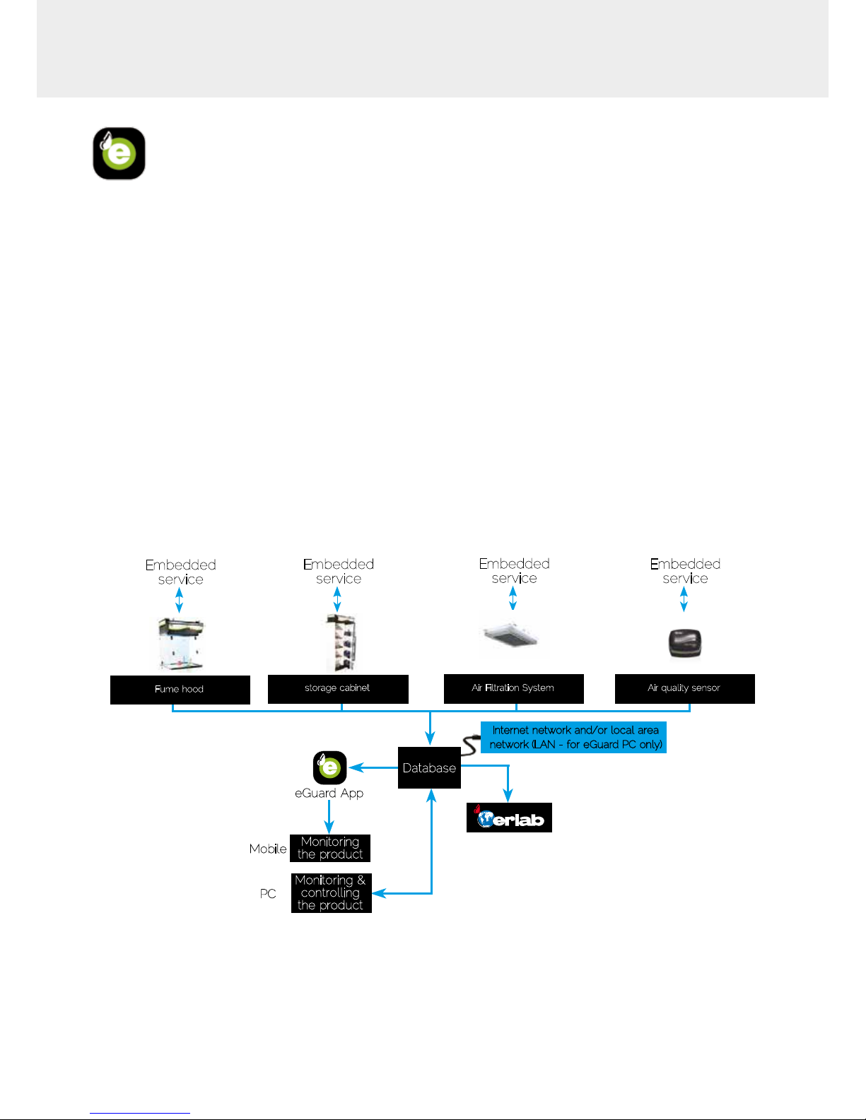
The connectivity of Captair Smart fume hoods allows you to monitor all your safety settings remotely.
After registering your product on line, download eGuard App and:
- Stay in touch wherever you are
- Receive safety alerts
- Access your statistics usage
- Make the most of an exclusive warranty program
Connectivity principle
Ecosystem designed for simpler use and safer protection
Ethernet-TCP-IP
Embedded
service
Fume hood
Internet network and/or local area
network (LAN - for eGuard PC only)
Database
Monitoring
the product
Monitoring &
controlling
the product
eGuard App
Mobile
PC
Embedded
service
storage cabinet
Embedded
service
Air Filtration System
Embedded
service
Air quality sensor
Page 10
10
Captair Smart
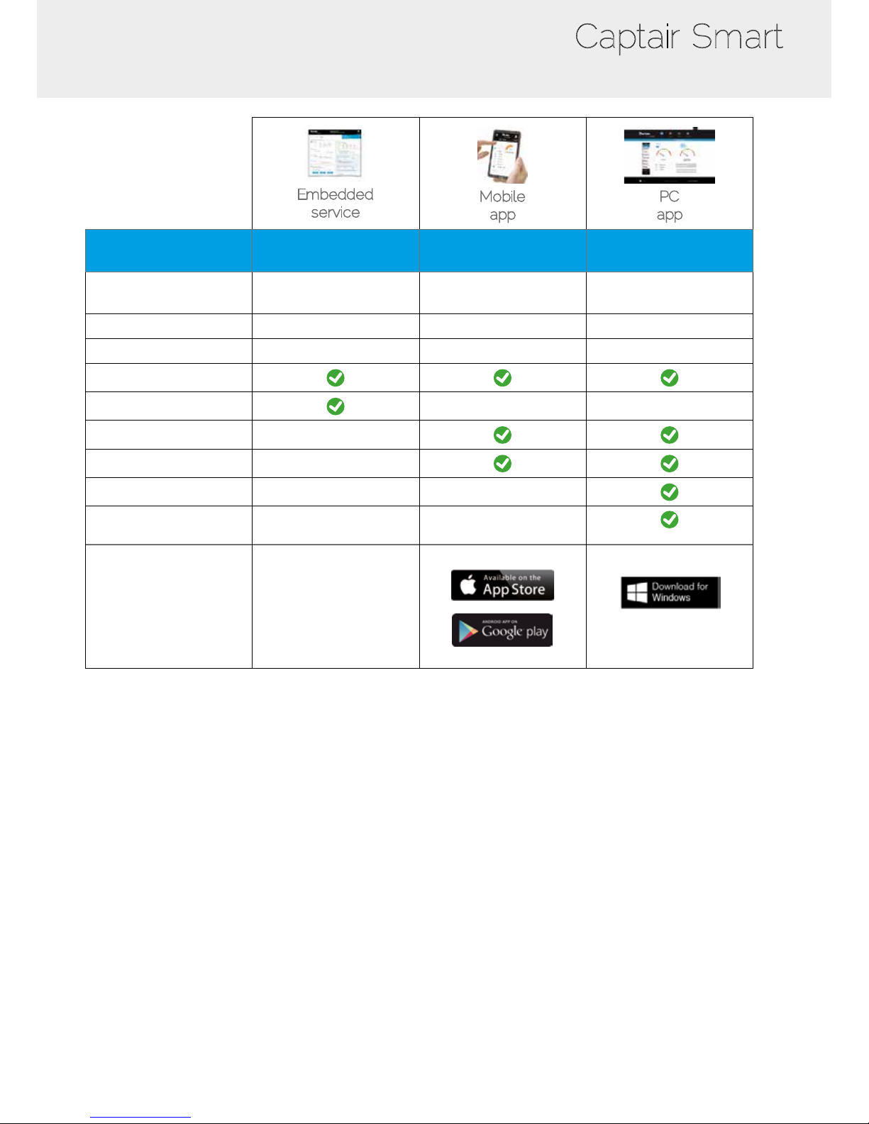
3 Versions
Embedded
service
Mobile
app
PC
app
Conditions
of use
Direct connection on PC
with data cable (RJ45)
Web connection
(via 3G/4G)
Web and/or local
connection
Hardware requirements 1 PC + 1 cable
1 Apple or Android
Smartphone
1 PC connected to
Internet or local network
Parameters Monitoring + Controlling Monitoring Monitoring + Controlling
Data access One unit Multiple units Multiple units
Historical data access
Historical data download
Alerts
Multiple units monitoring
Multiple user accounts
Automatized status report
(except if local connection)
Download
available on
www.erlab.com
Page 11
11
User Manual
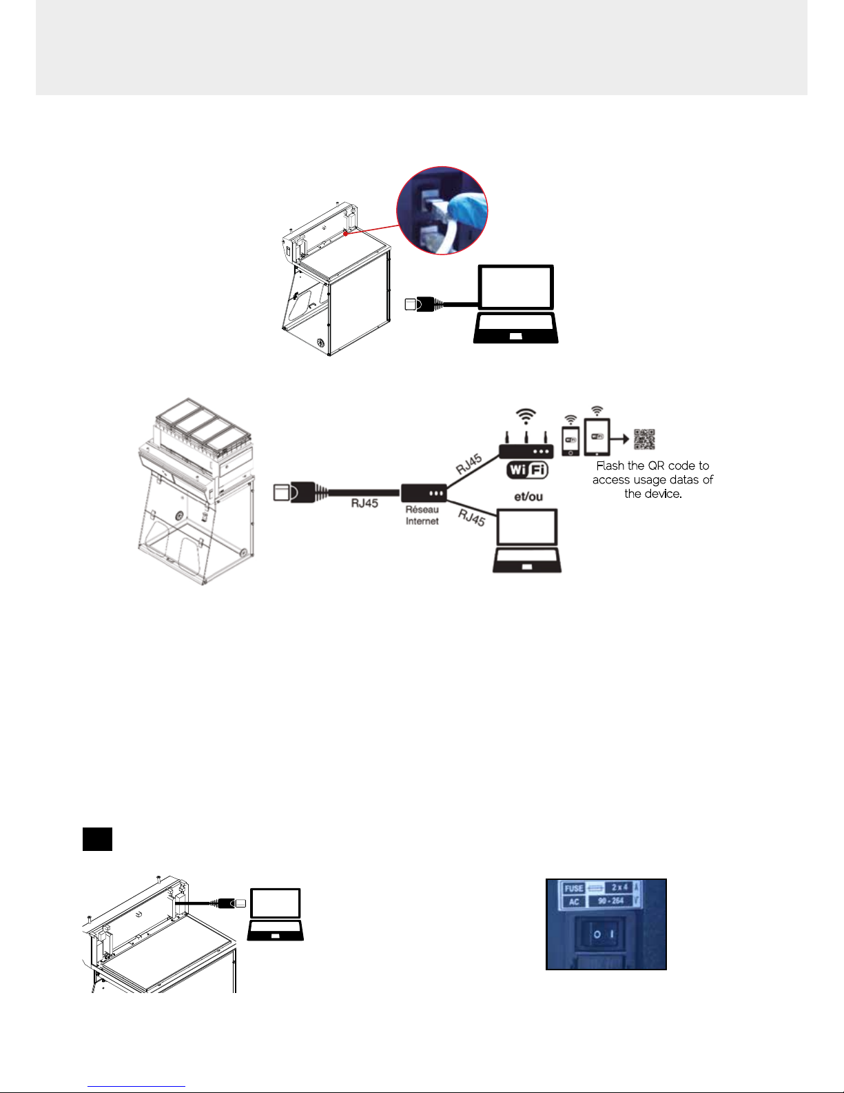
Options of connection
Embedded service
RJ45
Mobile or computer app
Flash the QR code to
access usage datas of
the device.
Accessing the Administrator interface
To monitor the parameters and modify the settings of the unit
In order to connect:
• Use a computer equipped with a Ethernet port (to plug the RJ45 cable)
• WIFI of the computer must be switched off
• Web browser (Internet Explorer, Edge, Chrome, Mozilla Firefox, Safari, …) must be installed on the computer
N.B: RJ45 cable used to plug the unit to the computer is provided.
1
Direct connection on computer
• Check that main switch (at the back of the
control panel on fume hoods and storage
cabinets) of the device is ON
• Take RJ45 cable (black) already connected
on the unit and rolled at the back of the control
panel.
Page 12
12
Captair Smart
2
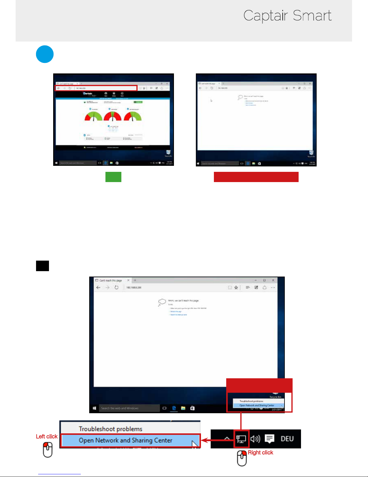
Open your web browser, type the following IP address 192.168.0.200 into the address bar and validate
OK
You are connected to the embedded software
You enter the « Status » page and you can have
access to the « Settings » using the following
credentials:
Login : erlab / Password : smart
Please go to page 16
Page is not accessible
Computer network parameters are not allowing
the access to the embedded software.
Apply the following procedure
Page is not accessible
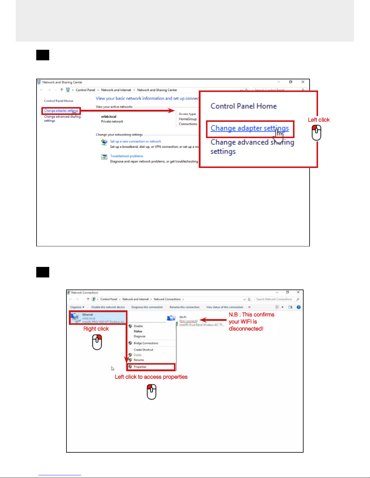
1
Modify computer network parameters
Right click
Left click
Network
parameters
Page 13
13
User Manual
2
Access to the Network and sharing center
Left click
3
Access to the network connection
Right click
Left click to access properties
N.B : This conrms
your WIFI is
disconnected!
Page 14
14
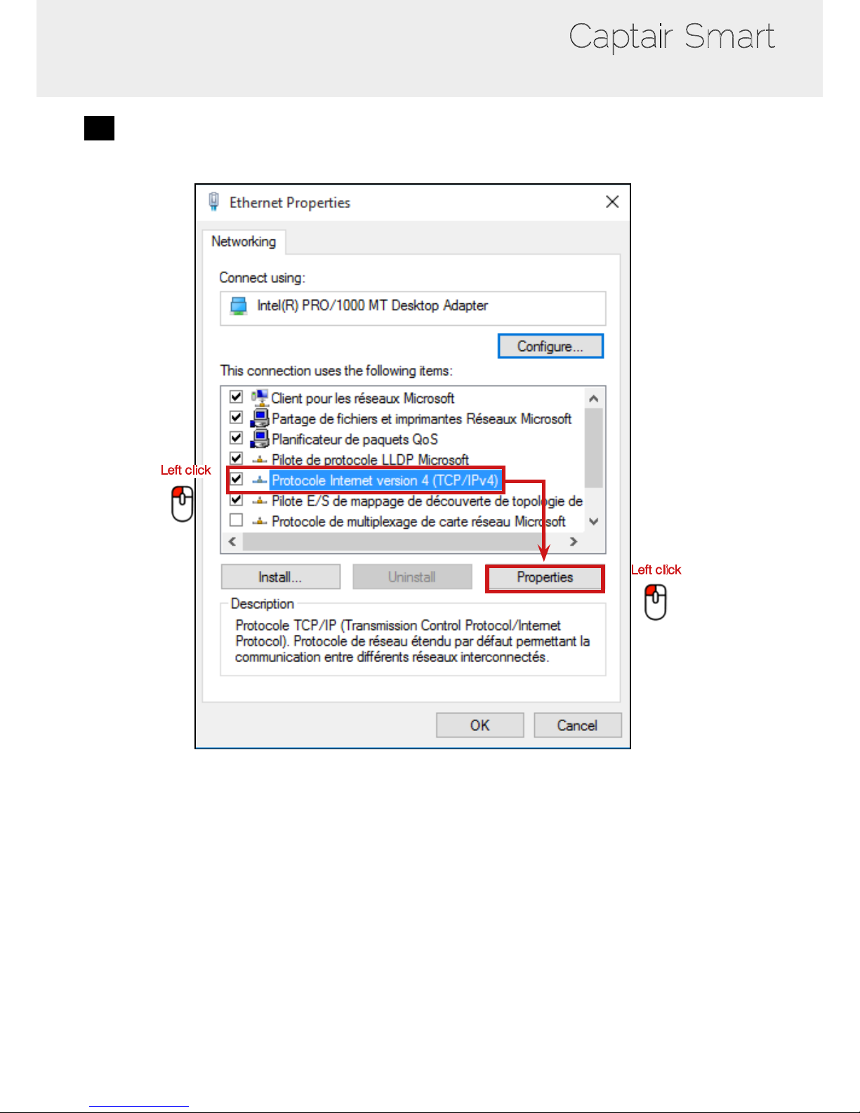
Captair Smart
4
Enter compatible network parameters as indicated below
Left click
Left click
Page 15
15
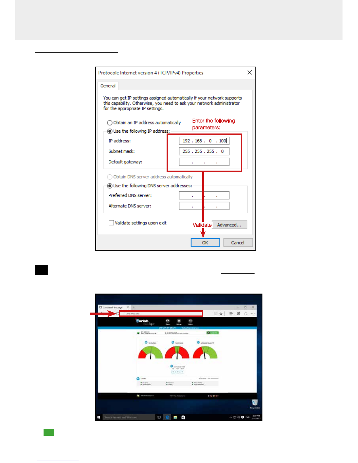
User Manual
Write down your existing parameters before changing them in order to be able to set your initial parameters after the operation!
Enter the following
parameters:
Validate
5
Open your web browser again, type again the following IP address 192.168.0.200 and validate
• OK : You are connected to the embedded software
You enter the « Status » page and you can have access to the « Settings » using the following credentials: :
Login : erlab / Password : smart
Page 16
16
Captair Smart
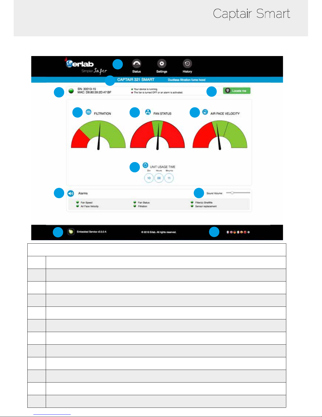
Administrator interface description
1
6
7
2
3
4
5
8
9
10
11
12
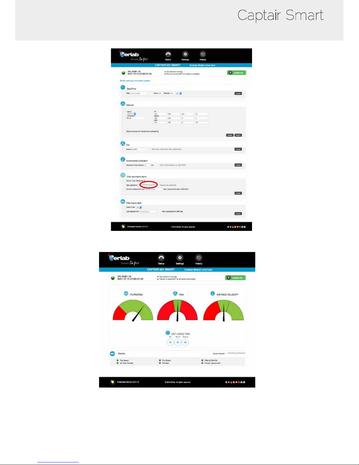
Status page details
1 Choose active interface page
2 Device ID: Model
3 Device ID: serial number, MAC address, device status
4 Unit location
5 Molecode Option Gauge: indicates the saturation level of the main carbon lter(s)
6 Fan Gauge: indicates the fan status
7 Air Face Velocity: indicates the air face velocity
8 Device use time since fan was last started
9 Device alarm statuses (see alarm triggering conditions)
10 Volume setting
11 Embedded service version
12 Choose language
Page 17
17
User Manual
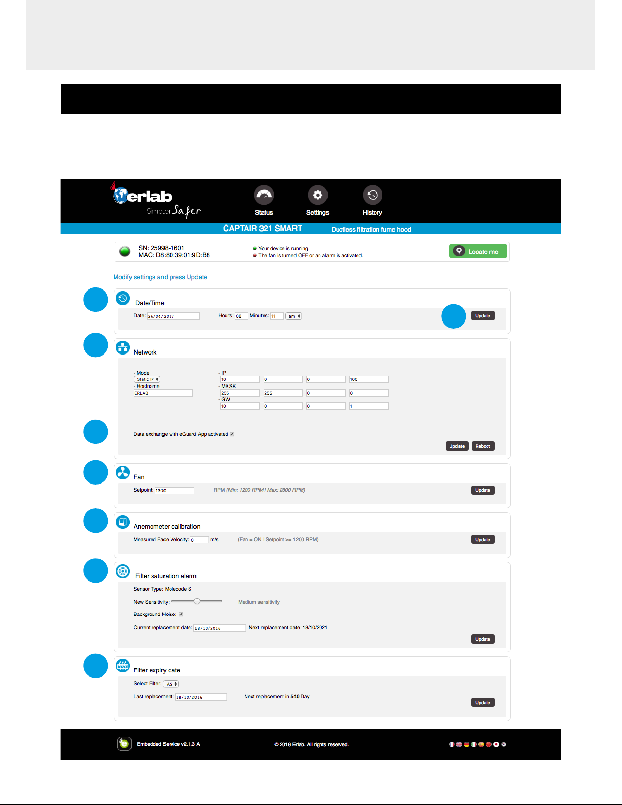
Access to the settings is protected by the following credentials:
User name: erlab
Password: smart
1
5
2
3
4
6
7
8
Page 18

18
Captair Smart
Settings page details
1 Device time and date settings
2
Device network settings
Mode: Selected IP protocol
Hostname: Device name on network
IP: IP address of the device
MASK: network mask
GW: Network gateway
Modify network settings :
Default mode : DHCP
Each unit is identied with its hostname : ER-UNIT-S/N
Hostname example for a Captair 321 Smart, S/N: 25698
Hosname will be: ER-321-25698
This hostname is displayed on the IP Adress label located on the back of the control panel
If the unit is not connected to a DHCP servor, the unit will automatically switch to its defaut IP address:
192.168.0.200
3
Activate/Deactivate the exchange of information
This allows the transmission of information from the device to the eGuard server for:
- remote monitoring via eGuard App (mobile &PC)
- receiving usage reports
4 Device fan setpoint settings
5
Anemometer settings :
Please check the anemometer settings procedure
6
Alarm saturation lter (Molecode option)
Sensor type indication (VOCs: volatile organic compounds/ A: Acids / F: Formaldehyde)
Sensor sensitivity settings:
VOCs sensor (5 settings) : High sensitivity, Medium/High Sensitivity, Medium Sensitivity, Medium/Low Sensitivity,
Low Sensitivity
A and F sensors (3 settings) : High sensitivity, Medium Sensitivity, Low Sensitivity
Sensor replacement
Enter replacement sensor date, display the next sensor replacement date
7
Filter replacement date:
Indicates the lter type (AS: organics vapors / BE+:Acids, inorganics, organics, and solvents vapors /
K : Ammonia vapors / F : Formaldehyde vapors / HP: powders)
For units equipped with carbon and HEPA lters, please use the carbon lter indication
Last replacement:
Counter showing the number of days the lter(s) can be used relative to its/their service life expiry date
8 Conrm settings key (please validate each setting )
Page 19
19
User Manual
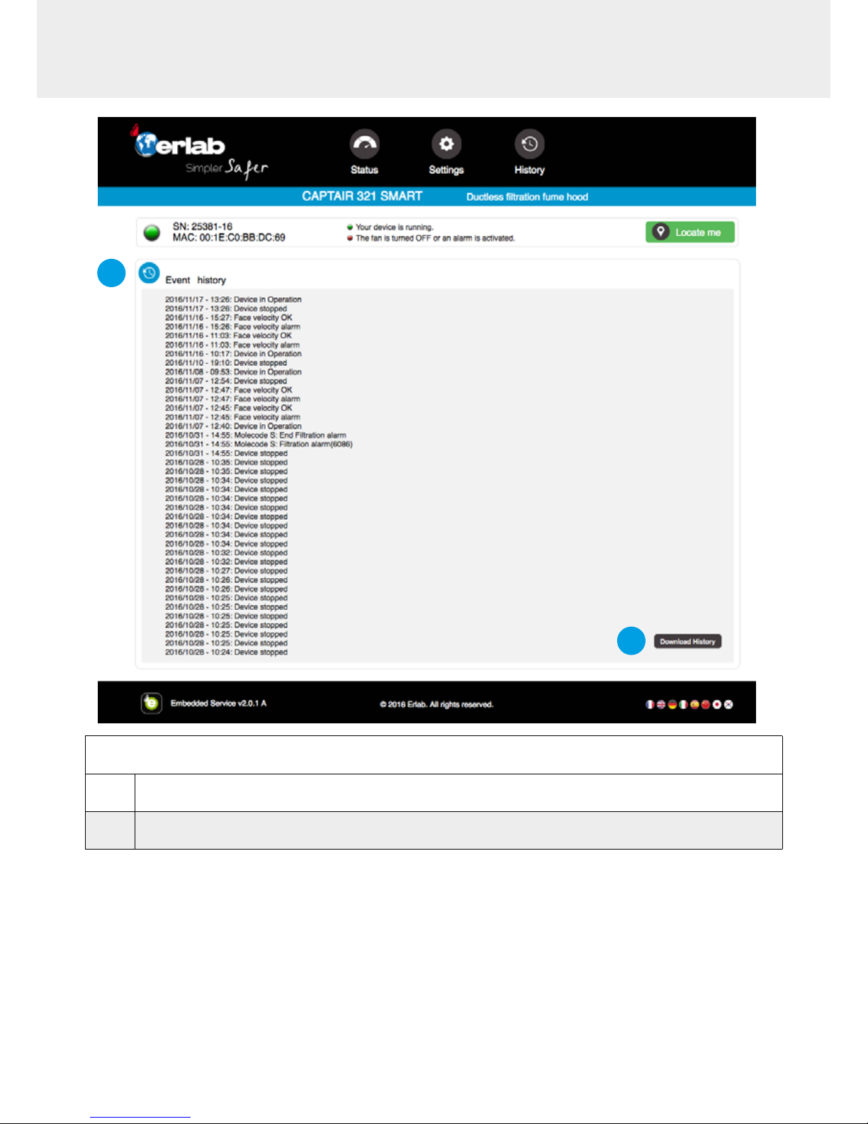
Log page details
1 Displays the device’s event log
2 Used for downloading the log in .csv format
1
2
Page 20
20
Captair Smart
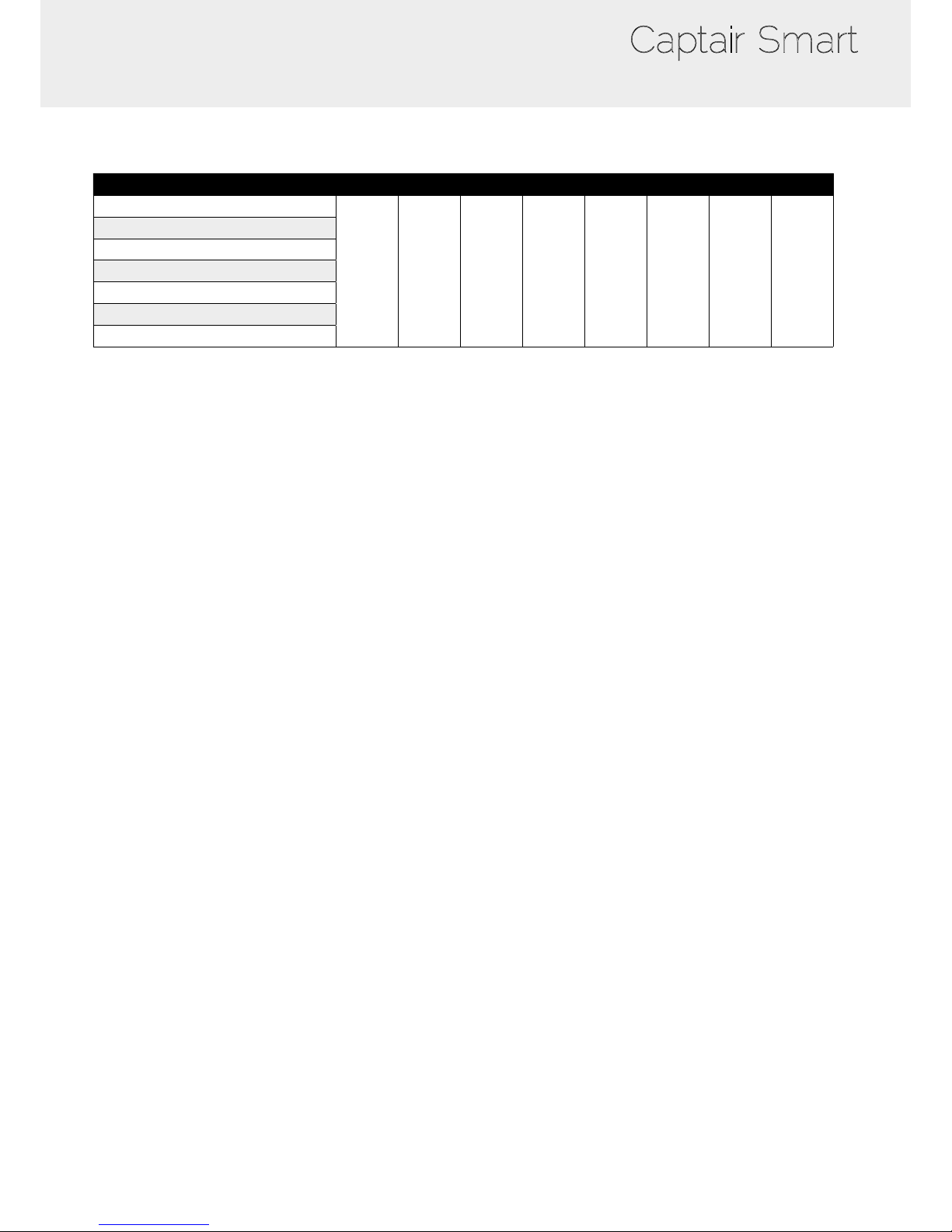
Fan setpoints per filtration column type
Unit / Type of ltration column 1P 1C 1C1P 1P1C 1P1C1P 1P2C 2C1P 2C
321
1800
RPM
2200
RPM
2500
RPM
2550
RPM
2800
RPM
2800
RPM
2800
RPM
2600
RPM
391
481
392
483
633
714
Page 21
21
User Manual
Procedure for automatic detection for the saturation of a
molecular filter using acetone
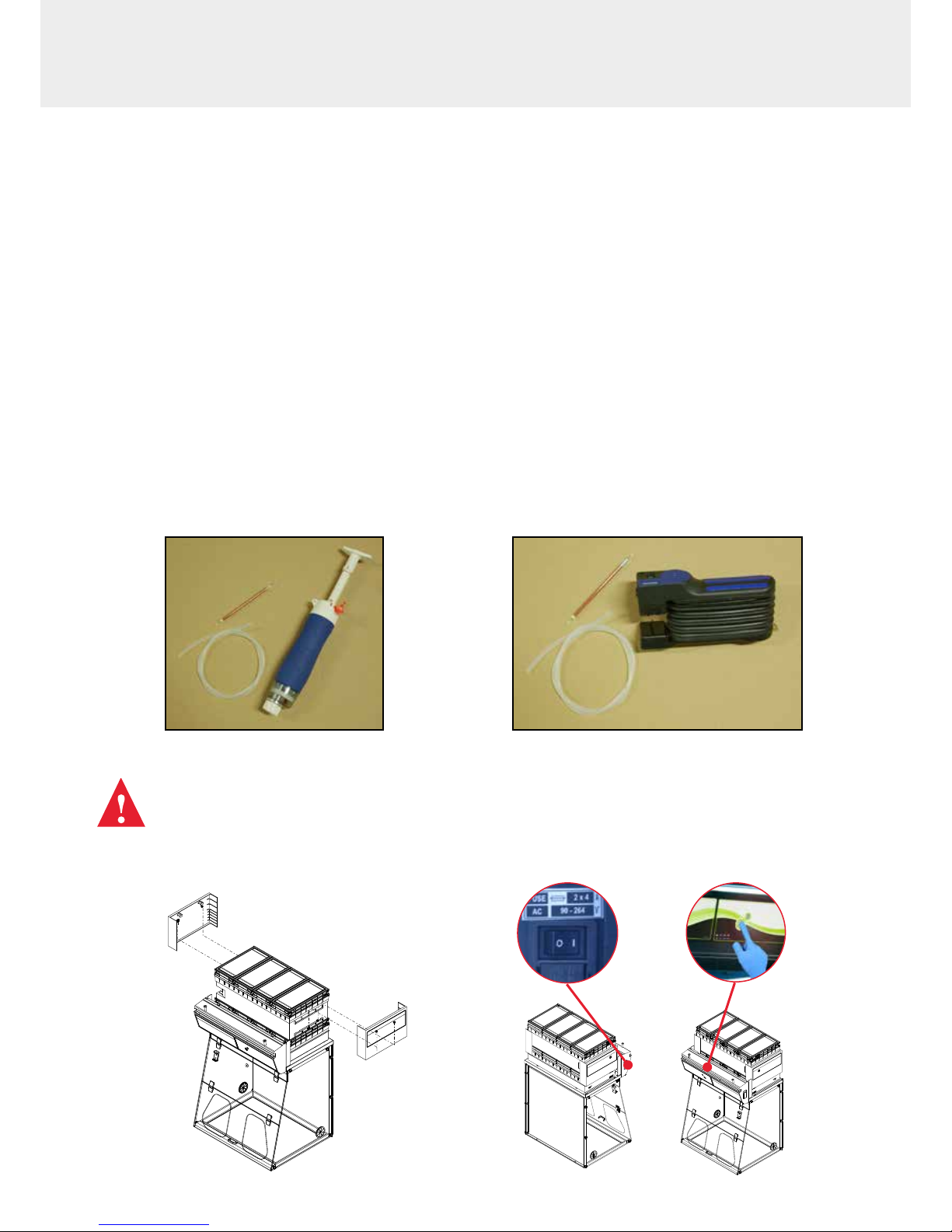
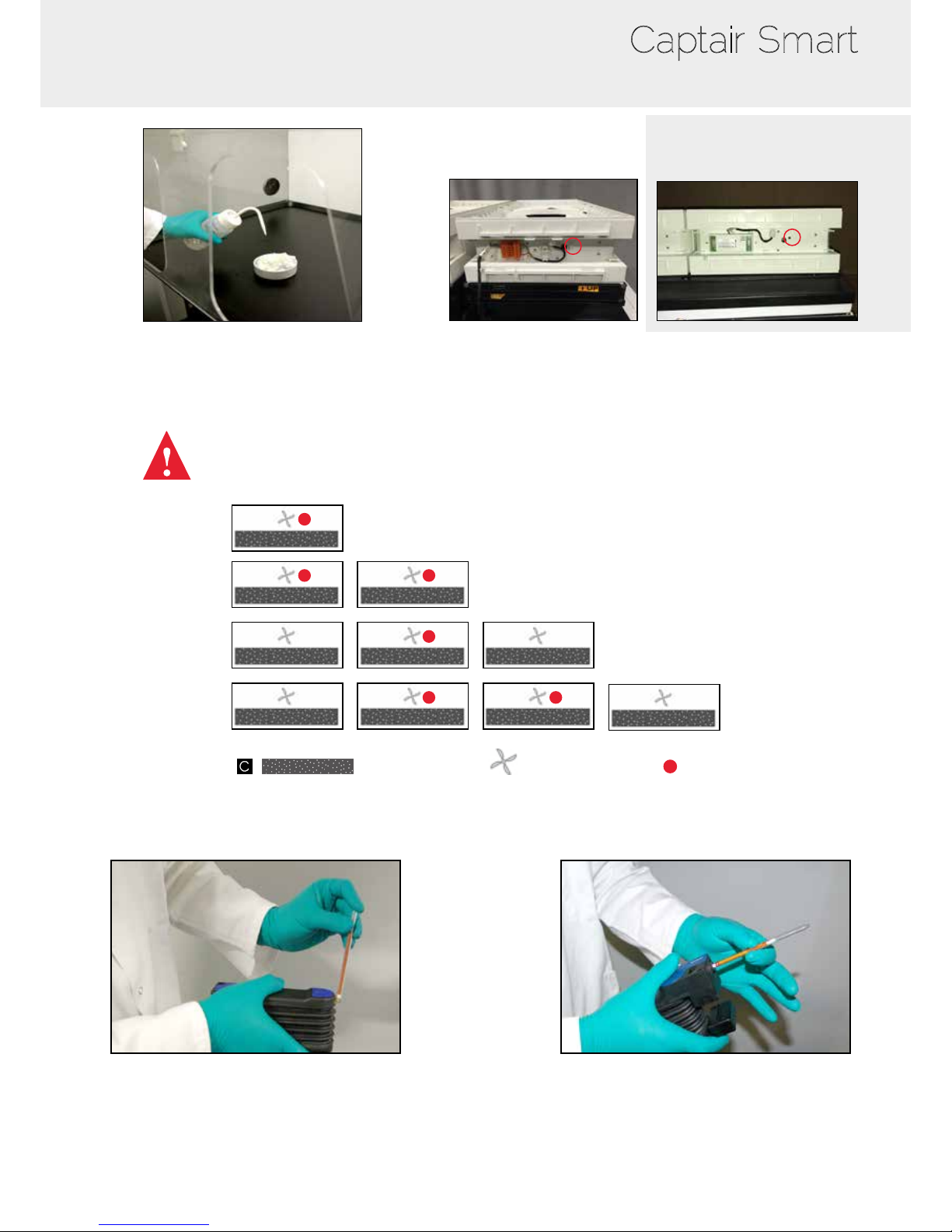
Acetone evaporates easily and quickly at room temperature and can be used as a tracer to check mocular lters saturation.
Following procedure provides three methods to determine activated carbon lters saturation, evaporating a small amount of
acetone withing the Captair Smart fume hood and using either a colorimetric tube for acetone, Molecode S saturation sensor
or a PID device. The result of the test will indicate weither it is necessary to replace lter or not.
Required material:
• 5 mL of acetone (not provided)
• Absorbing cloth (not provided)
• Cup or crucible (not provided)
• Hose (provided)
• Sampling pump (not provided)
• Colorimetric tube (not provided)
Remove protection covers
Turn on the unit and start the air ow
Not provided materials can be sourced from various manufacturers, such as Gastec, Draeger,
RAE System or authorised distributors.
Always use gas sampling pump together with detector tube from the same brand
Ref. Gastec tube: 151 L (pump 2 times)
Ref. Draeger tube: 81 03 381 (pump 1 time)
Ref. RAE tube: 10-111-40 (sample 100cc)
Saturation detection using colorimetric tubes
Page 22
22
Captair Smart
Turn on the unit and start ventilation
Pour 5 mL of acetone on an absorbing cloth placed
within the fume hood
Connect to the appropriate fan box depending on your unit model:
Carbon lter
Fan Box
Hose connection
321
392
483 / 633
714
Remove sample port cork and connect hose
to the fan box
Break tip off a fresh detector tube.
Sampling pumps are usually equipped
with tube tip breaker.
Insert the tube into the pump inlet, in
the correct direction. Tubes are usually
marked to indicate direction.
-European
fan connection:
- North American
fan connection:
Page 23
23
User Manual
Proceed with air sampling following manufacturer’s recommendation
If test result is positive to acetone, change lter(s)
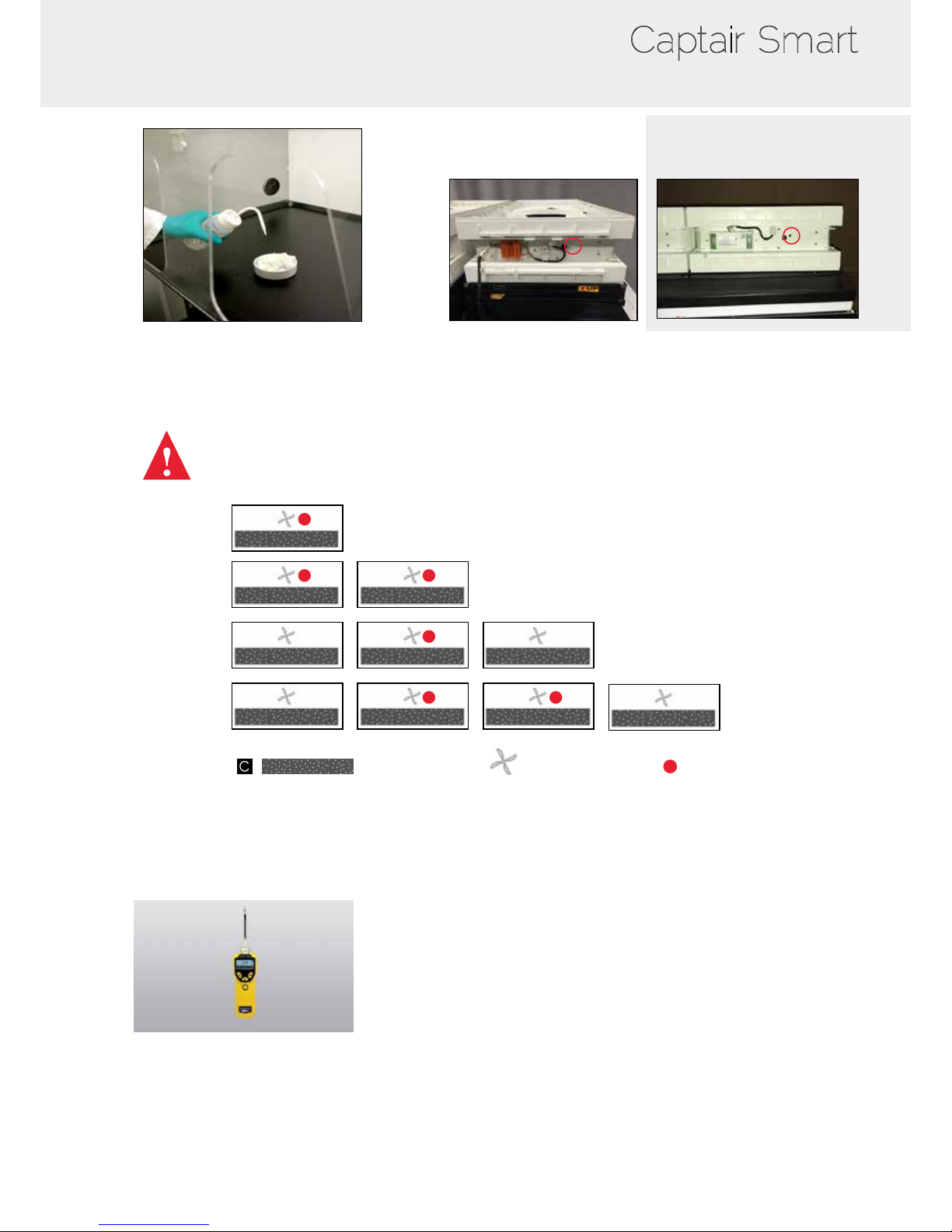
Saturation detection using PID Device:
Required material :
• 5 mL of acetone (not provided)
• Absorbing cloth (not provided)
• Cup or crucible (not provided)
• Hose (provided)
• PID device (not provided)
Materials not provided can be sourced from various RAE System manufacturer or authorised distributors.
Remove protection covers
Turn on the unit and start air ow
Page 24
24
Captair Smart
Pour 5 mL of acetone on an absorbing cloth placed
within the fume hood
Connect to the appropriate fan box depending on your unit model:
Carbon lter
fan box
Hose connection
Remove sample port cork and connect hose
to the fan box
321
392
483 / 633
714
Connect hose to the PID sampling probe
Select ‘acetone’ to be detected in PID menu (see user manual
if necessary).
If acetone concentration is more than to 5 ppm, change lter(s)
-European
fan connection:
- North American
fan connection:
Page 25
25
User Manual
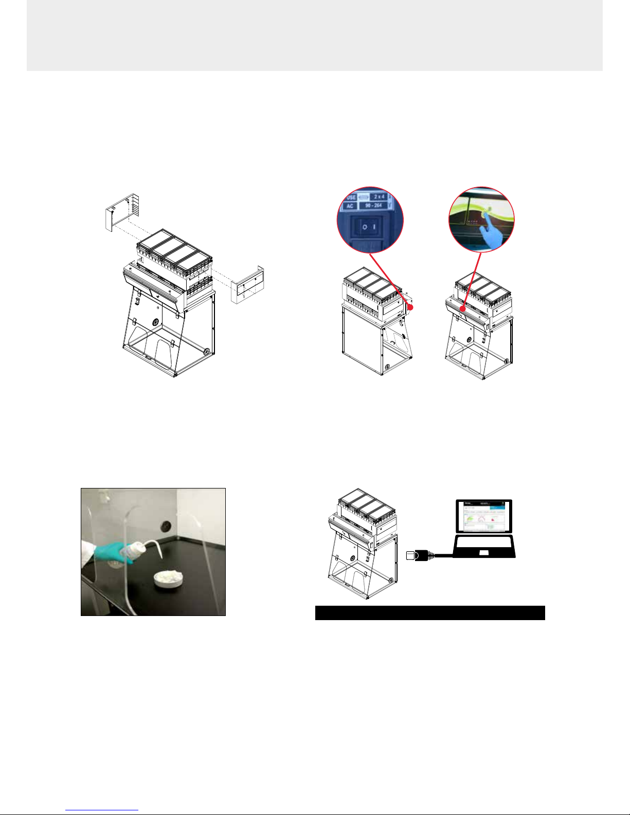
Default IP : 192.168.0.200
RJ45
Connect to unit embedded service
Saturation detection using Molecode S sensor
Required material:
• 5 mL of acetone (not provided)
• Absorbing cloth (not provided)
• Cup or crucible (not provided)
Remove protection cover
Turn on the unit and start air ow
Pour 5 mL of acetone on an absorbing cloth placed
within the fume hood
Page 26
26
Captair Smart
Set Molecode sensitivity on ‘high’
Open ‘Status’ page
Check ltration efciency
If needle is in red area, change lter(s)
Page 27
27
User Manual
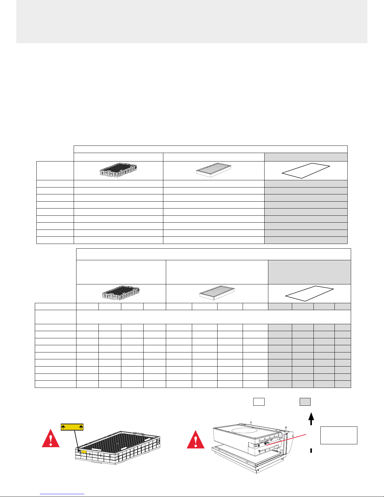
Replacing the filters
Your device is equipped with FLEX™ lter technology that was congured to the user’s protection needs when the device
was purchased. The conguration of the lter column is dependent on the applications carried out in the enclosure. These
applications may change over time. Your FLEX™ lter technology can therefore be recongured if your fume hood is used
for applications other than those anticipated when the device is rst set up. If so, please contact us so that we can verify that
the current conguration is safe or it needs to be congured.
The table below summarises all possible Flex™ lter technology congurations for your device
Captair 321 - 391 - 481 Smart models
Molecular lter HEPA lter H14 / ULPA Pre-lter
Column
Conguration
1C x1 x1
2C x2 x1
1 P x1 x1
2 P x2 x1
1P 1C x1 x1 x1
1P 2C x2 x1 x1
1C 1P x1 x1 x1
2C 1P x2 x1 x1
1P 1C 1P x1 x2 x1
OptionalStandard
Captair 392 - 483 - 633 - 714 Smart models
Molecular lter
HEPA lter H14 / ULPA Pre-ltre
Models 392 483 633 714 392 483 633 714 392 483 633 714
Column
Conguration
1C x2 x3 x3 x4 x2 x3 x3 x4
2C x4 x6 x6 x8 x2 x3 x3 x4
1 P x2 x3 x3 x4 x2 x3 x3 x4
2 P x4 x6 x6 x8 x2 x3 x3 x4
1P 1C x2 x3 x3 x4 x2 x3 x3 x4 x2 x3 x3 x4
1P 2C x4 x6 x6 x8 x2 x3 x3 x4 x2 x3 x3 x4
1C 1P x2 x3 x3 x4 x2 x3 x3 x4 x2 x3 x3 x4
2C 1P x4 x6 x6 x8 x2 x3 x3 x4 x2 x3 x3 x4
1P 1C 1P x2 x3 x3 x4 x4 x6 x6 x8 x2 x3 x3 x4
UP
Air Flow
Fan module
#1
Page 28
28
Captair Smart
Replacing the HEPA H14 / ULPA lters
Pre-requisites
• The operative responsible for replacing the lter is kept up-to-date with the exhaustive list of products handled in
the fume hood by the user so that the correct EPI can be used
• The laboratory is empty when the operation is carried out
• The laboratory is ventilated by mechanical or natural means while the operation is carried out
Minimum protective equipment
• One-piece overall + overshoes + bouffant cap
• Laboratory gloves (latex or nitrile)
• Protective glasses
• Breathing mask with particle lter (P3)
Notice: additional equipment could be required.
This procedure is applicable to HEPA/ULPA lters located at the bottom of the ltration columns and designed to trap
powders handled inside the device enclosure.
Strict chronological order to follow:
1- Switch on the device fan
2- Carefully spray the bottom surface of the HEPA/ULPA lter
(paint with NON FLAMMABLE propellent), to be done inside the enclosure
3- Allow at least 5 minutes with the fan running for the spray to dry
4- Shut down and unplug the device and disconnect the fan module power supply cable and the sampling tubes from the
sampling area (if installed)
5- Carefully remove the molecular lter(s) (if present) and the fan module
6- Carefully unwrap the new HEPA/ULPA lter
Keep the plastic lm and cardboard box so that you can use it later to pack up the used lter
Lay out the lm on a at surface in the immediate vicinity of the operation so that it is at the ready
7- Carefully remove the used HEPA/ULPA lter and immediately place it contaminated-side down onto the plastic lm
8- Clean the lter housing and the enclosure (using water + surfactant)
9- Package up the used lter + contaminated equipment
Seal the plastic lm tightly
10- Place the sealed package in the box the new carbon lter came in, then seal it using adhesive tape, clearly write «used
lter» on the packaging.
Have the lter disposed of via a suitable disposal process in accordance with the applicable regulations.
To nd out more, please contact your usual advisor.
11- Fit the new HEPA/ULPA lter, main molecular lter (if present) and the fan module, followed by the backup molecular
lter (if present). Make sure that all the column components
12- Reconnect the device’s various cables and hoses, switc h the device back on and check the air speed using the
anemometer calibration procedure via the administrator interface
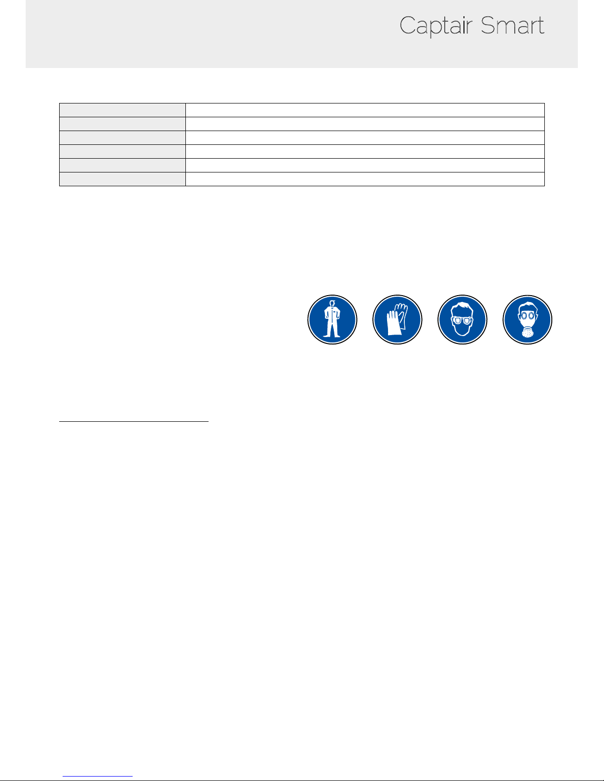
Type AS
For organic vapors
Type BE +
Multi-application for acid and organic vapors
Type K
For ammonia vapors
Type F
For formaldehyde vapors
HEPA H14
For powders
ULPA
For powders
The table below summarises the different types of carbon lters that Erlab® offers along with their elds of application.
Page 29
29
User Manual
The «Revolving» System
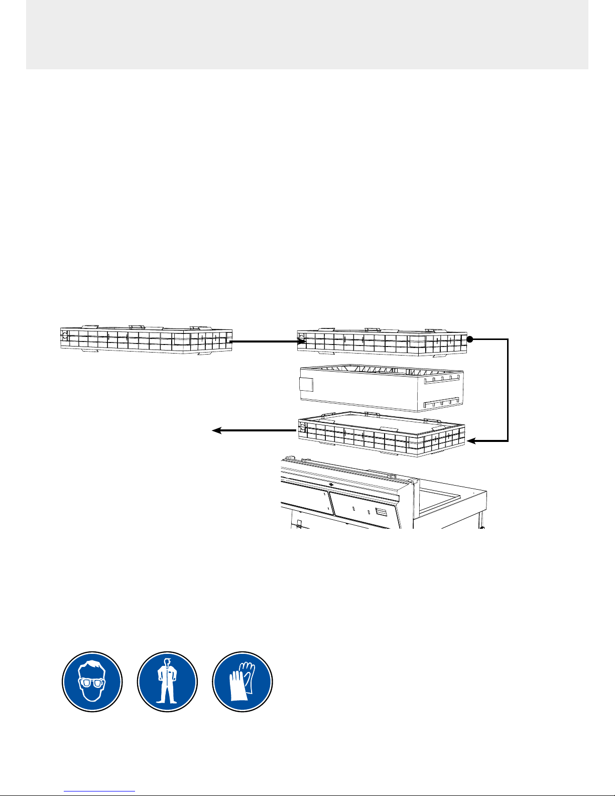
Molecular lter replacement ( The “revolving system” may be used with following Flex™ technology types 2C / 1P2C
/ 2C1P)
This simple concept involves placing one chamber equipped with a molecular detection system between two lters having
the same capacity. When the main lter is saturated, the molecules are directed to an identical back-up lter that is placed
just above the detection chamber.
This system prevents all molecules from being released into the environment since they are automatically absorbed by the
back-up lter. The back-up lter replaces the main lter when the main lter has reached its maximum saturation point. A new
lter is then installed in place of the back-up lter. This cycle may be repeated indenitely.
Compared to traditional ltration systems, the “revolving lter” concept increases the retention capacity of the lter by 25%
and decreases replacement costs by 25%.
New lter
Main lter
back-up lter
Energy recycling system
Filter Replacement Procedure
For these operations, we strongly recommended that the user or maintenance technician wear the necessary safety equipment,
including: safety glasses, lab coat and gloves
Page 30
30
Captair Smart
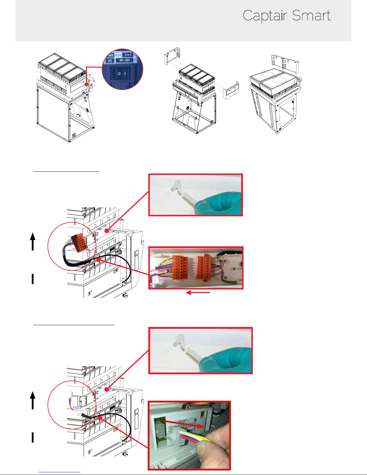
Switch off the fume hood
Remove the protective shields on either side of the hood
Example: 321 Smart
Example: 392 Smart
- European fan connection:
Disconnect the power supply to the fan hood
followed by the fan module hose (if the device is tted with a type A or F
Molecode)
Air Flow
- North American fan connection:
Disconnect the power supply to the fan hood
followed by the fan module hose (if the device is tted with a type A or F
Molecode)
Air Flow
Page 31
31
User Manual
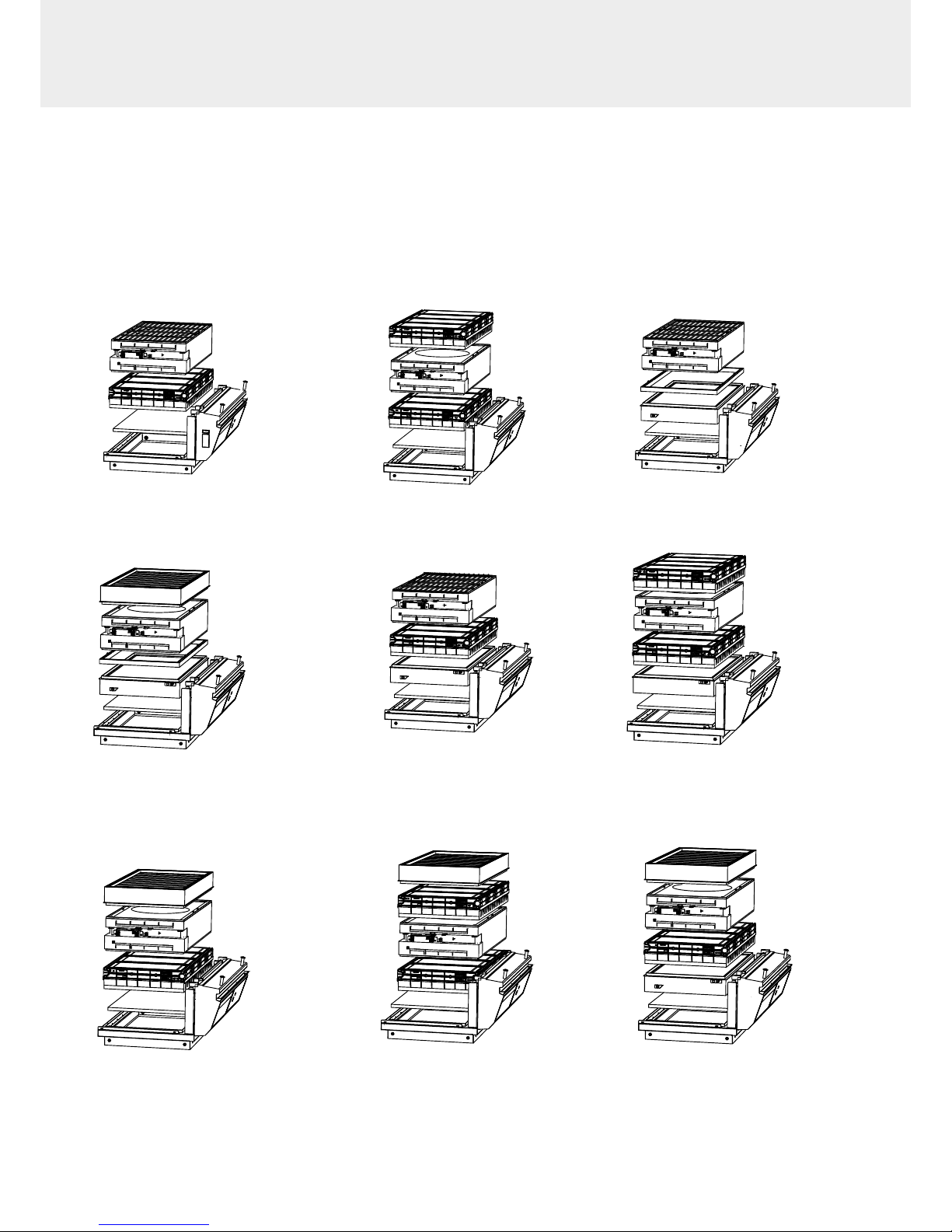
1C 2C
1P 2P
1P1C
1P2C
1P2C
1C
2C
1C 2C
1P
2P
2C
2P
Models Captair 321 - 391 - 481 Smart
1. Identify wich column conguration below applies to your hood. (See your Valipass label)
2. Unstack the ltration column(s) above the fume hood.
3. After carrefuly removing the lters from their packaging, assemble the column per the conguration below.
4. If your column conguration changed, Apply the correct fan setpoint for the ltration column conguration
(see fan setpoints)
1C 2C
1P 2P
1P1C 1P2C
1C1P
2C1P
2C1P
1C 2C
1P 2P
1P1C 1P2C
1C1P
2C1P
1P1C1P
Page 32
32
Captair Smart
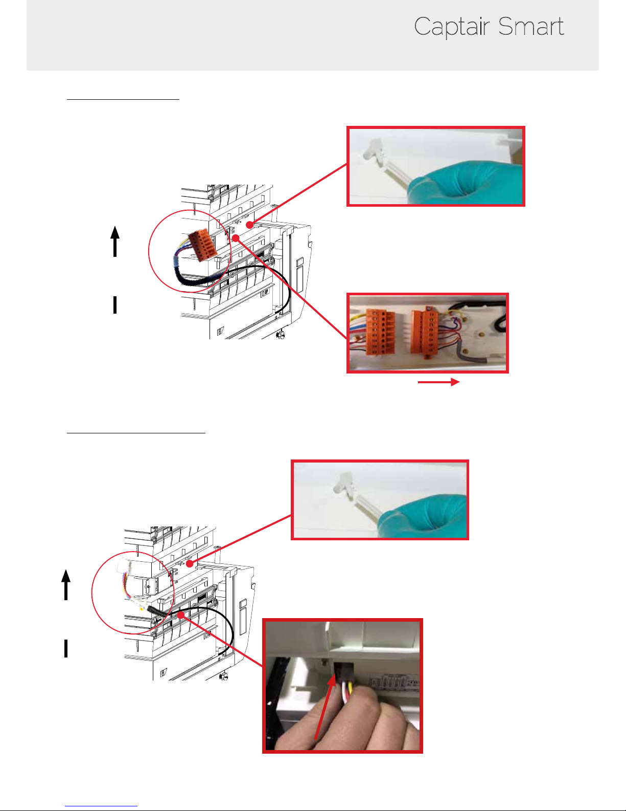
- European fan connection:
Reconnect the power supply to the fan hood
and the hose to the sampling port.
(If the device is tted with a type A or F Molecode)
When reassembling the ltration column, be
sure that the fan module is positioned correctly
to access your connection points.
Air Flow
- North American fan connection:
Reconnect the power supply to the fan hood
and the hose to the sampling port.
(If the device is tted with a type A or F Molecode)
Air Flow
When reassembling the ltration column, be
sure that the fan module is positioned correctly
to access your connection points.
Page 33
33
User Manual
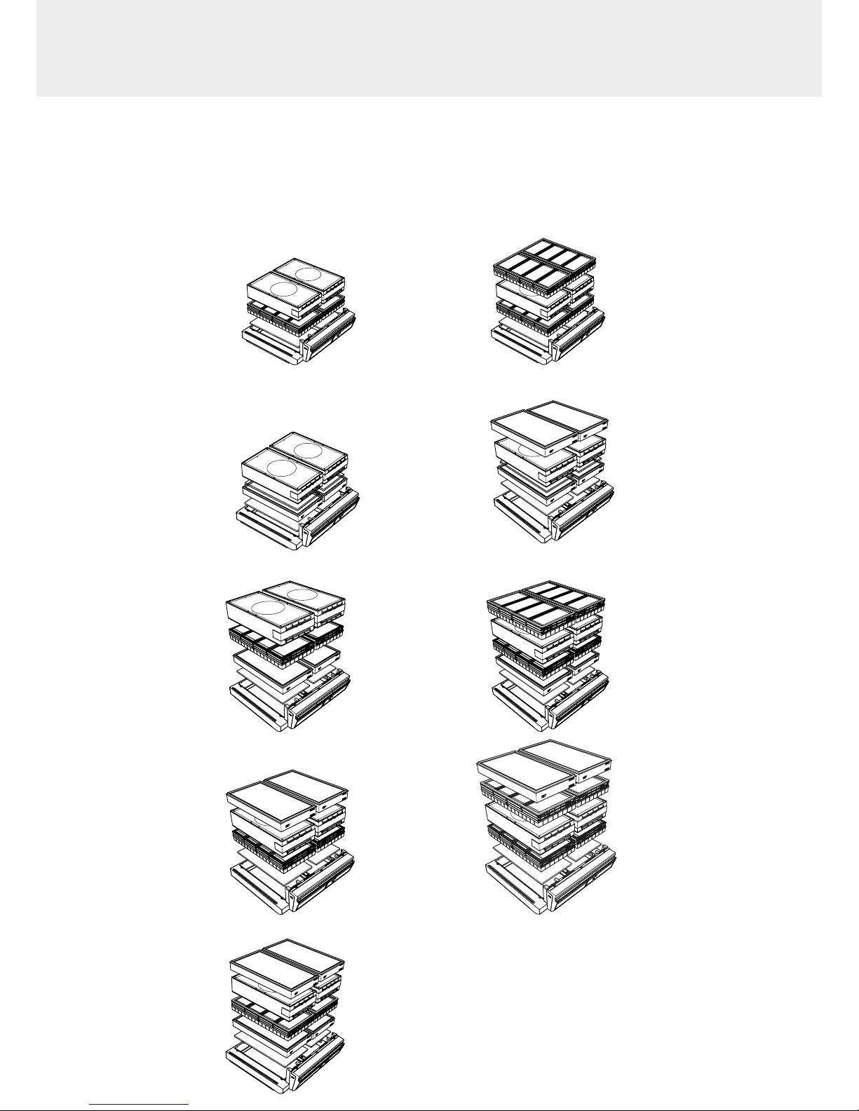
1C 2C
1P 2P
1P1C 1P2C
1C1P
2C1P
1P1C1P
Models Captair 392 - 483 - 633 - 714 Smart
1. Identify wich column conguration below applies to your hood. (See your Valipass label)
2. Unstack the ltration column(s) above the fume hood.
3. After carrefuly removing the lters from their packaging, assemble the column per the conguration below.
4. If your column conguration changed, Apply the correct fan setpoint for the ltration column conguration
(see fan setpoints)
Page 34
34
Captair Smart
7
392
392
714
714
483 - 633
483 - 633
1
1 1 1
2 3
3 3 32 2 22 2 2
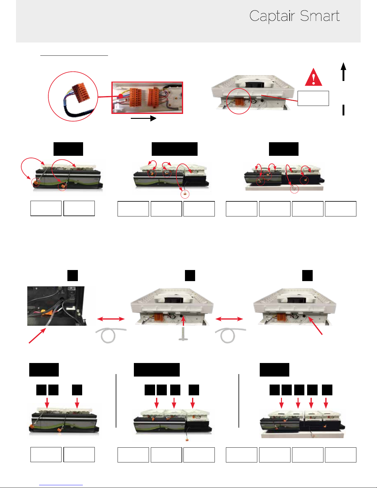
Units equiped with molecode optional lter saturation sensor (A & F type)
Fan module
#2
Fan module
#2
Fan module
#1
Fan module
#1
Fan module
#1
Fan module
#2
Fan module
#2
Fan module
#2
Fan module
#2
Fan module
#1
Fan module
#1
Fan module
#1
Fan module
#1
Fan module
#3
Fan module
#3
Fan module
#3
Fan module
#3
Fan module
#4
Fan module
#4
Air Flow
- European fan connection:
Page 35
35
User Manual
392
392
714
714
483 - 633
483 - 633
1
1 1 1
2 3
3 3 32 2 22 2 2
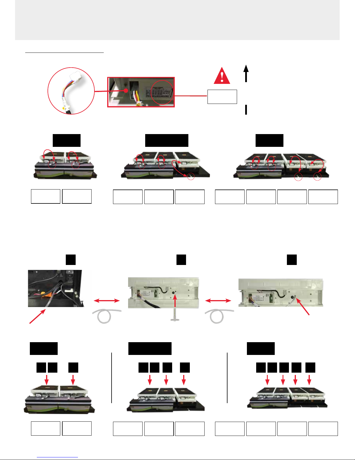
Units equiped with molecode optional lter saturation sensor (A & F type)
Fan module
#2
Fan module
#2
Fan module
#1
Fan module
#1
Fan module
#1
Fan module
#2
Fan module
#2
Fan module
#2
Fan module
#2
Fan module
#1
Fan module
#1
Fan module
#1
Fan module
#1
Fan module
#3
Fan module
#3
Fan module
#3
Fan module
#3
Fan module
#4
Fan module
#4
Air Flow
- North American fan connection:
Page 36
36
Captair Smart
Recommendations for storing and using the filters
New lter shelf life and storage conditions:
New activated carbon molecular lters must be stored at in their original packaging at a temperature of between +10°C / 50°
F and +50°C / 120° F and a humidity level < 85% RH.
If these conditions are adhered to, the maximum time a lter can be stored before use depends on the type of carbon used:
AS type carbon molecular lter 2 years from the date of delivery
BE+ type carbon molecular lter 2 years from the date of delivery
BE type carbon molecular lter 1 year from the date of delivery
F type carbon molecular lter 1 year from the date of delivery
K type carbon molecular lter 1 year from the date of delivery
If the maximum shelf life is reached, we recommend to not install lters.
- HEPA H14 and/or ULPA lters must be stored upright and kept dry; there is no limit to the time they can be stored.
Predicted service life of a lter once put into use:
The service life of a molecular lter depends on the operations carried out in the ductless fume hood as well as the conditions
of the environment in which it is used.
We recommend replacing the lter annually (if used 24/7).
ERLAB offers 3-point validation of your handling operations based on a scientic analysis carried out by its laboratory
specialists via the global Erlab Safety Program (E.S.P) which includes the Valiquest questionnaire:
• Feasibility of handling operations under a recirculating fume hood
• Type(s) of lter(s) to use and ltration column conguration
• Predicted service life of the activated carbon molecular lters
How does the E.S.P service work?
• The customer completes the Valiquest questionnaire and sends it by email to Erlab
• The Erlab laboratory specialists analyze the questionnaire and issue a Valipass certicate
The Valipass certicate is afxed to the new devices at the factory. If the chemical processes in the hood change, a new
valiquest is completed and is sent by email after revalidation.
The certicate contains the following: the list of products handled in the hood, the lter type required for these chemicals,
serial number, lter life time, the traceability information used to track how the device is used and the molecular lter saturation
detection methods.
The activated carbon molecular lter(s) must be replaced when the period in months specied on the Valipass
certicate expires
To ensure their safety, we invite users who have not had their application validated via the VALIQUEST questionnaire or whose
device is not covered by a VALIPASS usage certicate, to contact ERLAB or their usual distributor to arrange a new usage
validation for the device in question.
Failing that and/or in the absence of information regarding device usage:
ERLAB is unable to provide any guidance as to the predicted service life of the lter(s).
In such cases, we strongly recommend:
• That the molecular lters are replaced at least every 12 months and that a regular lter saturation checking protocol is put
in place (please contact us for individual advice on this subject)
• That the HEPA or ULPA particulate lters are replaced at least every 36 months
Page 37

37
User Manual
Replacement frequency of filtration breakthrough sensor,
Molecode option
Molecular lters saturation detection alarm – Molecode (S : solvents or A : acids or F: formaldehyde - tted as an integrated
option in your unit, work using semi-conductor or electrochemical sensor that must be changed every :
5 years for the Molecode S
2 years for Molecode A and F
After this period, Erlab cannot guarantee performances stability nor detection sensitivity.
Equipment replacement requires the intervention of a qualied engineer, able to replace internal components and perform
system new conguration. The change requires less than one hour.
Erlab Maintenance department and accredited partners can provide this service. (service not available in all countries)
For further information, please get in touch with your contact person or Erlab dealer/distributor or visit our website
Admissible weighs on working surfaces
Tempered glass
work top
Stainless steel
work top
Trespa® Top Lab
PLUS
work top
50 kg/m
2
1187 lb/ft
2
110 kg/m
2
2610 lb/ft
2
110 kg/m
2
2610 lb/ft
2
Captair Smart 321 15 kg 33 lbs 35 kg 77 lbs 35 kg 77 lbs
Captair Smart 391 20 kg 44 lbs 45 kg 99 lbs 50 kg 110 lbs
Captair Smart 481 25 kg 55 lbs 65 kg 143 lbs 65 kg 143 lbs
Captair Smart 392 20 kg 44 lbs 60 kg 132 lbs 60 kg 132 lbs
Captair Smart 483 30 kg 66 lbs 80 kg 176 lbs 80 kg 176 lbs
Captair Smart 633 40 kg 88 lbs 100 kg 220 lbs 100 kg 220 lbs
Captair Smart 714 45 kg 99 lbs 115 kg 254 lbs 115 kg 254 lbs
Page 38

38
Captair Smart
Cleaning and maintenance
Mechanical item checks
Hinges:
Hinges must be properly attached and must allow any items on the front side of the hood to be instantly and easily lifted
upward.
Acrylic Parts:
These parts must be clean; white streaks or spatters indicate rather heavy use of acid (hydrochloric acid) or products
handled at a high temperature. Ensuring the transparency of the walls is a part of regular maintenance for the enclosure.
Cleaning the enclosure
The enclosure must be cleaned on a regular basis.
This may be accomplished in several ways:
- With soapy water followed by rinsing with clear water and drying with a soft, non-abrasive absorbent paper towel.
- Or with a commercial pH neutral neutralizing product followed by drying with a soft, non-abrasive, absorbent paper towel.
Coated Metal Parts:
- These must be inspected and free from any traces of corrosion.
- Check that there is no stagnant water in the spill tray.
- Clean the spill tray if necessary.
Page 39
V10_2017_12 - Erlab France - Technical data are not contractual. Erlab
®
DFS SAS reserves the right to modify the present document without prior notice.
1
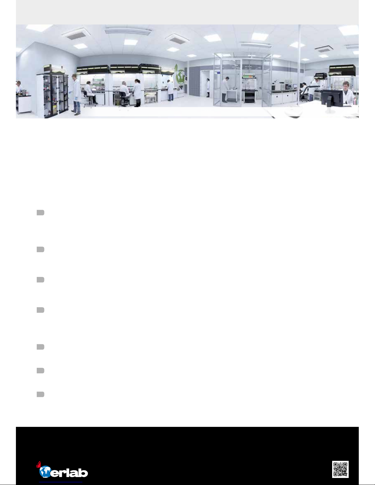
Erlab R&D Laboratory
The engineers and chemists in our state-of-the-art R&D laboratory understand molecular ltration. We are committed to
designing products that are safe and of the highest quality, strive to improve our products, and continuously develop new
products that provide greater protection in the laboratory.
2
Strict Safety Standards
We hold ourselves to the highest standard and adhere to the strict AFNOR NF X 15-211: 2009 ltration safety standard
as endorsed by ANSI Z9.5-2012.
3
A Published Chemical Listing
It all begins here. Without this listing, we are not compliant with AFNOR NFX 15-211. Our in-house laboratory tests, as well
as independent testing to verify the retention capacity of over 700 chemicals for our lters.
4
Independent Testing
Erlab lters have been independently tested multiple times at various concentrations guaranteeing that our safety
solutions all adhere to the strict performance criteria of the AFNOR NF X 15-211:2009 standard assuring that the emission
concentration at the lter exhaust will always be lower than 1% of the TLV.
5
Application Questionnaire (Valiquest)
Our laboratory specialists will recommend the appropriate ltration fume hood, type of lter, and personalized advice.
6
Certicate of Validation for the chemicals used in the hood
A certied PhD chemist issues a Certicate of Validation with a list of the chemicals approved for use in the hood.
7
Our Safety Program
We back up our products 100%. This program includes your specialized chemical evaluation, validation of your hood
upon installation, and a ltration safety specialist at your service to ensure that your hood is operating to its full potential.
We provide safety, we protect your health
Erlab invented the ductless fume hood in 1968. With more than 45 years of experience in the eld of chemical ltration and
protection of laboratory personnel; we know the formula for safety. With Erlab, you will never have to wonder or worry if our
products are safe. We build each one of the following 7 ingredients into our products, and without all of them, your health
and safety will be compromised.
France
+33 (0) 2 32 09 55 80 │ [email protected]
Germany
0800 330 47 31│ [email protected]
China
+86 (0) 512 5781 4085 │ [email protected]
Italy
+39 (0) 2 89 00 771 │ [email protected]
Malaysia
+60 (0) 7 3 555 724 │ [email protected]
Spain
+34 93 673 24 74 │ [email protected]
North America
+1 800-964-4434 │ [email protected]
United Kingdom
+44 (0) 1722 341 940 │[email protected]
www.erlab.com
About Erlab
Le laboratoire de Recherche et Développement Erlab
Erlab’s state of the art Research & Development Laboratory relying exclusively on ltration
 Loading...