

Page 1

Quick Start Guide for
T-PRO 4000 Transformer Protection Relay
In our ongoing efforts to run our business in an environmentally sensitive way, we are encouraging
the use of PDF manuals and software downloads, available from our website. For your convenience,
links are provided below to all software files to be downloaded.
If you do wish to have a hard copy manual or software on CD, you may request those from our
Customer Support team (contact info below).
If you are reading a hard copy of this document, download the soft copy (includes links) from
our website’s Support/Documents page, in the Quick Start Guide column.
http://www.erlphase.com/support.php?ID=documents
1. Downloading the required software and manual
a. The T-PRO 4000 comes loaded with the requested firmware version. All required
software, as well as the release description of the latest firmware version, is available on
the Software page of our website. Contact the Customer Support team for release
descriptions of any other firmware version.
b. Download the following software on your computer:
Relay Control Panel
T-PRO Offliner
USB Driver
ERL 61850 IED Configurator (if needed)
c. Install Relay Control Panel and T-PRO Offliner
d. Install the USB driver
e. Install Null Modem
Download the T-PRO 4000 User Manual. Other documents such as Drawings are also available
on the Documents page of our website.
2. Hardware and operating system requirements
Minimum hardware requirements:
• 1 GHz processor
• 2 GB RAM
• 20 GB available hard disk space
• USB port
• Serial communication port
Page 2
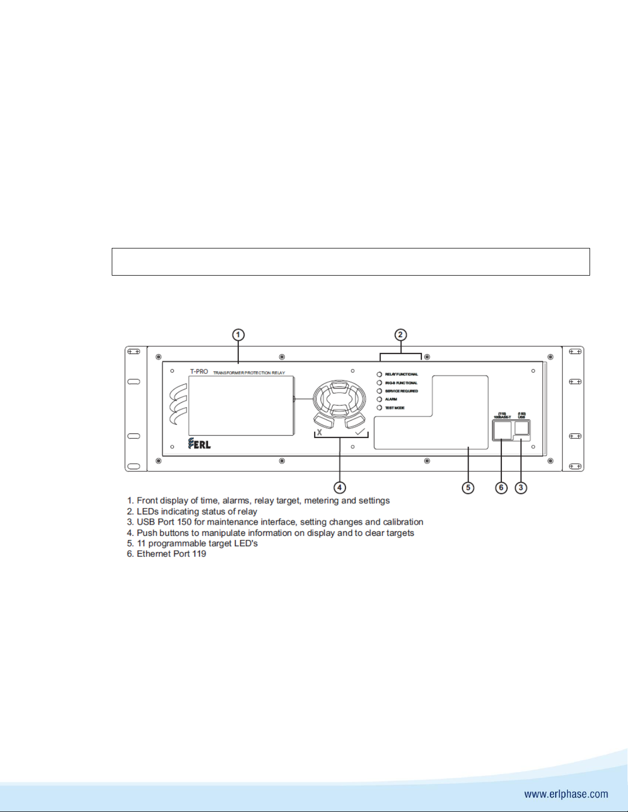
3. Unpacking and connecting the relay
The following items are included in the T-PRO 4000 carton pack:
• USB cable
• Letter of Compliance to ISO 9001:2015 standard
• Letter of Compliance to CE requirements (if requested)
There are no power switches on the relay. When the power supply is connected, the relay starts
its initialization process.
1. Connect power supply to #17/16, as shown in Figure 3/4. The wire used for the power supply
wiring shall be at least 18 AWG (1.02 mm2), 600 V.
2. Ground the T-PRO at #18, as shown in Figure 3/4
4. T-PRO 4000 relay front and rear panel layout
Figure 1 – T-PRO 4000 Front View (3U)
The relay is calibrated before it leaves the factory
Page 3
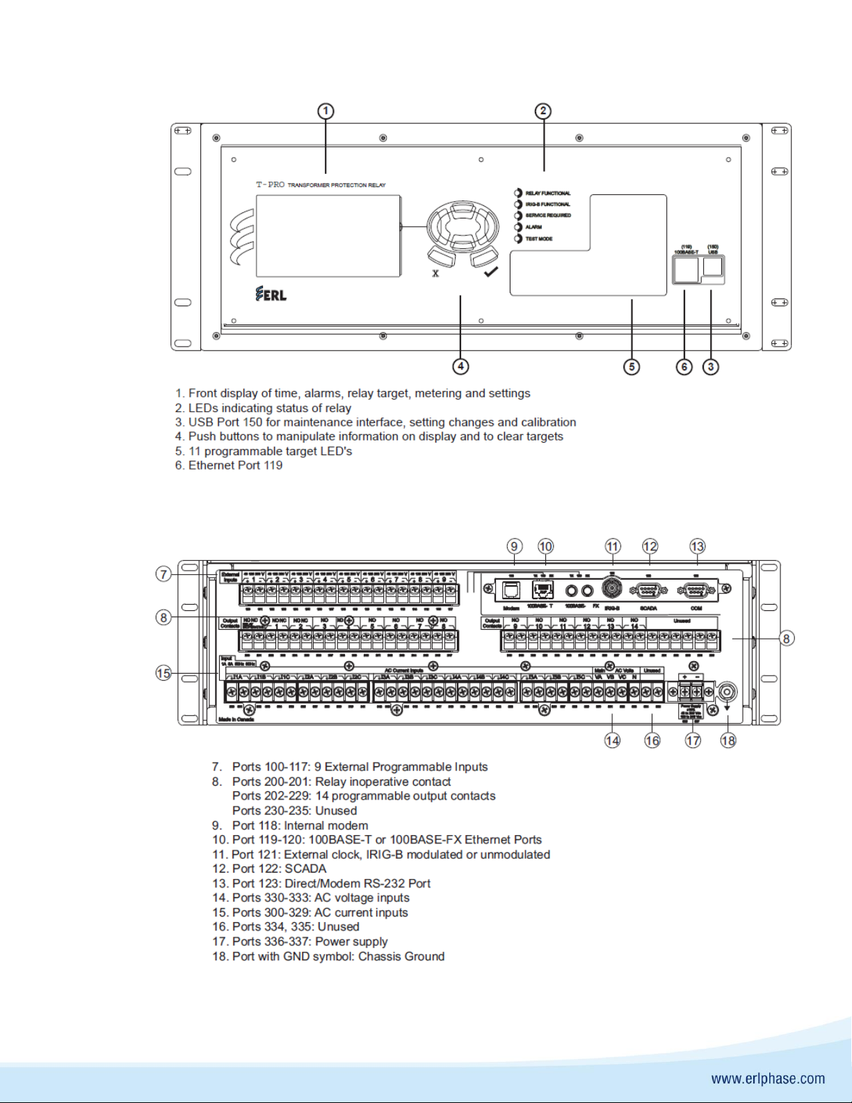
Figure 2 – T-PRO 4000 Front View (4U)
Figure 3 – T-PRO 4000 Relay Rear View (3U)
Page 4

Figure 4 – T-PRO 4000 Relay Rear View (4U)
5. Application notes
Refer to the following application notes for help connecting and configuring the T-PRO relay.
They may be downloaded from the Support section of our website on the Application Notes page
(scroll to Relay & Recorder section).
• Basic Instructions to Communicate with 4000 Series Relays
The Application Notes page also contains a range of other valuable T-PRO instructions and
descriptions of specific applications.
For further information and contact Customer Support at:
+1 204 477 0591 ext 1
The specifications and product information contained in this document are subject to change without notice. In case of inconsistencies between
documents, the version at www.erlphase.com will be considered correct. (D04482R00.00)
 Loading...