

ERL MIT161 Application And Commissioning Manual

AUGUST 2001
APPLICATION AND COMMISSIONING MANUAL
MIT161 RELAY
EASUN REYROLLE LIMITED
1

Issue No : 2nd Issue
Date of Issue : 30.08.2001
Department :TP-CTS
2

STARTER TRIP
SENSITIVE CURRENT PROTECTION
PROTECTION HEALTHY
EASUN REYROLLE INDIA
MIT161 RELAY
MIT
161
3

CONTENTS
PAGE
APPLICATION 5
INSTALLATION 12
COMMISSIONING 18
WIRING DIAGRAM 24
4

APPLICATION
1. INTRODUCTION
The type MIT161 numerical sensitive current protection relay combines the power and
flexibility of microprocessor technology. The relay is especially tuned to suit applications
where low settings, low burden and rejection of harmonic currents become a necessity.
The relay is suitable for high resistance earth fault protection and capacitor bank
unbalance current protection.
2. CHARACTERISTICS
MIT161 relay has two stage protection i.e. earth fault element and lowset element.
Earthfault element is provided with DTL characteristic and the lowset element is provided
with DTL & IDMTL (Standard Inverse 3 sec, Standard Inverse 1.3 sec, Very Inverse
Extremely Inverse and Long Time Inverse) characteristics.
3. RESET TIME DELAY
The lowset element IDMTL characteristic is also provided with reset time delay
characteristic for detecting “Flashing faults”.
The increasing use of plastic cables, both, conventionally buried types and aerial bundled
conductor types have given rise to the number of "pecking" or "flashing intermittent faults
on distribution systems. At the fault position, the plastic melts and temporarily reseals the
faulty cable for a short time, after which the insulation fails again. The same phenomenon
has occurred in joint boxes where an internal flashover temporarily reseals.
The behaviour of different types of over current relays under flashing fault condition is
compared in Fig.1. The repeating process often caused electromechanical disc relays to
"ratchet” up and eventually trip the faulty circuit provided that the reset time of the relay
was longer than the time between successive flashes. Early electronic IDMTL relays with
instantaneous reset features were not at all effective in dealing with this condition and
only tripped after the flashing fault had developed into a solid permanent fault.
To overcome this the MIT161 relay has a reset time setting which can be user
programmed to be either instantaneous or delayed from 1 to 60 seconds in step of 1 sec.
On the other hand, on overhead line networks, particularly where reclosers are
incorporated in the protected system, instantaneous resetting is desirable to ensure that, on
multiple shot reclosing schemes, correct grading between the source relays and the relays
associated with the reclosers is maintained.
5
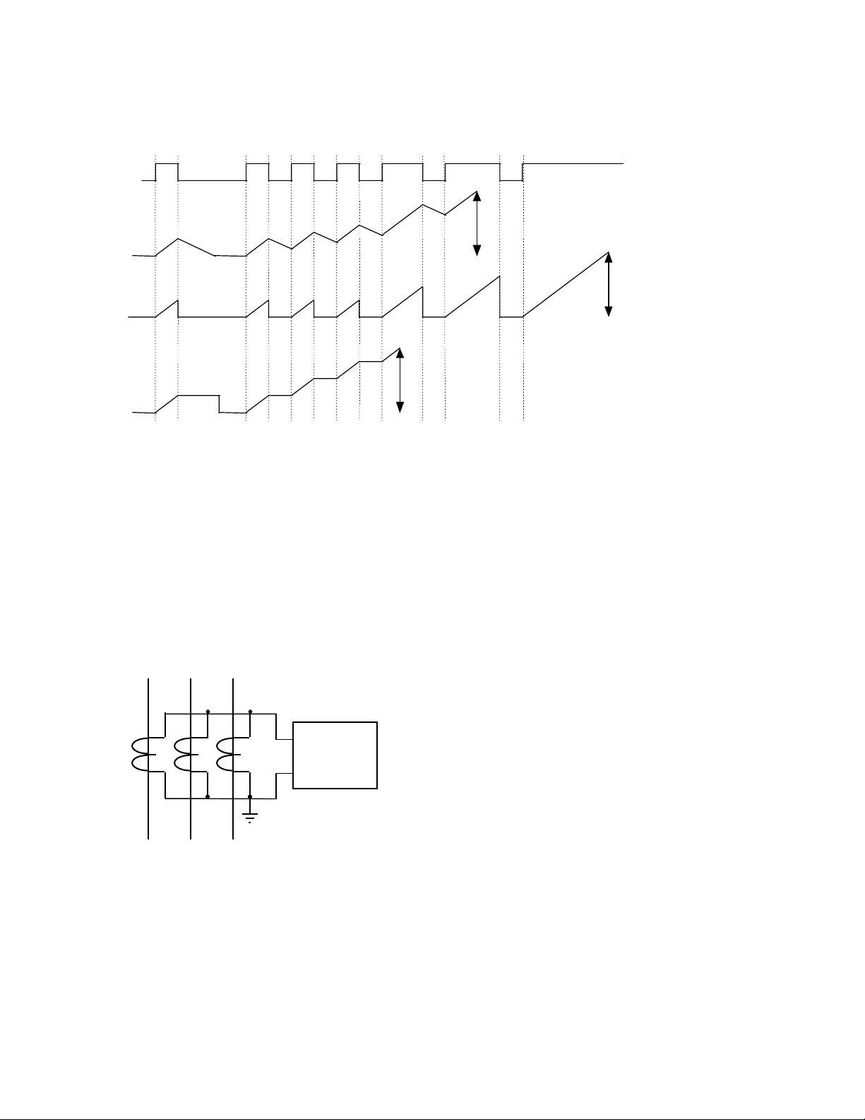
FAULT
CURRENT
Flashing Faults
Fault becomes
permanent
ELECTROMECHANICAL
SLOW RESET
STATIC
INSTANTANEOUS RESET
TRIP
NUMERICAL (MIT)
DELAYED RESET
Figure 1 Flashing Fault Protection
TRIP
TRIP
4. SYSTEM EARTH FAULT
Distribution Feeder Fault Current magnitude depends upon the amount of fault resistance
and it can vary from reasonable value to a very low value.
MIT161 has two elements, which can be set for IDMTL and SEF protection to get
complete protection for line ground fault.
YRB
MIT
161
Fig. 2. CT Residual Connection.
Fig.2 shows the CT residual connection for detecting earth faults.
6
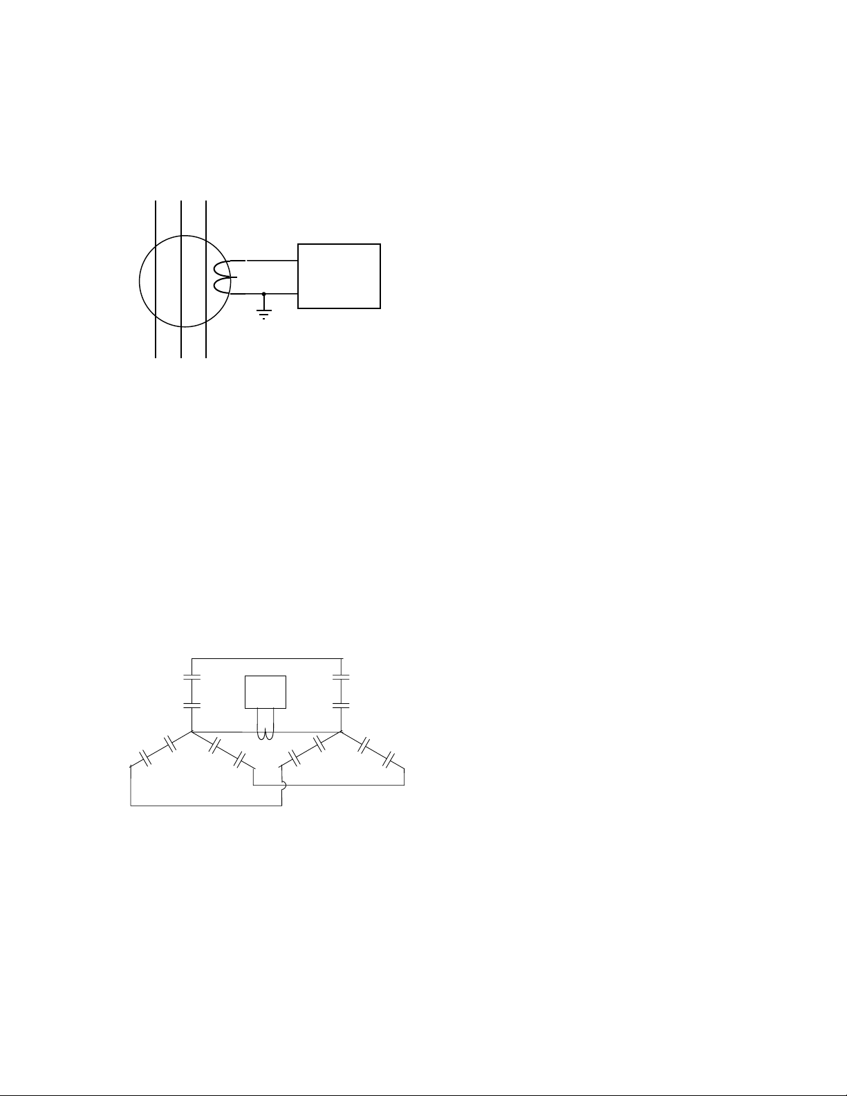
Fig.3 shows core balance CT connection for sensitive earth fault application.
YRB
MIT
161
Fig . 3 CBCT Connection
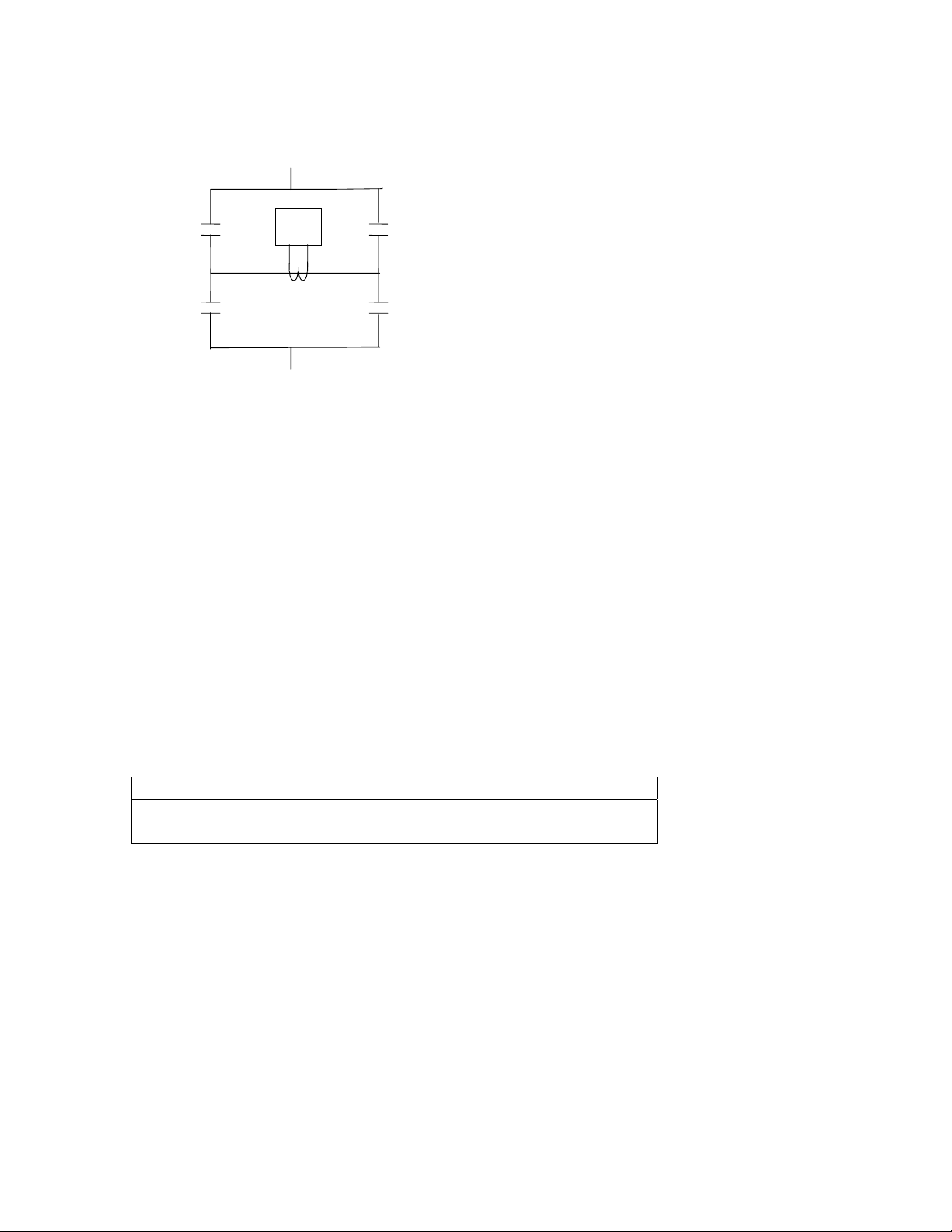
5. CAPACITOR UNBALANCE CURRENT PROTECTION
MVT161 can be used for unbalanced current protection of double star, delta and singlephase capacitor banks.
MIT
INSTALLATION
161
Fig .4. Double Star Capacitor Bank Neutral Unbalance Protection.
7
MIT
161
Fig.5. Single phase capacitor bank/ Delta connected bank unbalance protection.
Fig.5. shows single-phase capacitor bank / 3 phase delta connector bank unbalance
protection. When the relay is used for 3-phase delta connected bank unbalance protection,
3 MIT 161 relays have to be used.
6. TECHNICAL INFORMATION
6.1. Rating 1 Amp / 5Amps
6.2. Frequency 50 Hz
6.3. Auxiliary Supply
Nominal Voltage Voltage Range
24 / 30 / 48 / 110V DC 18 – 135 V DC
48/110/220 V DC or 110V AC 43 – 280V DC
6.4. Settings
Earth fault element 0.5% to 25% in steps of 0.5%
Low set element 0.5% to 25% in steps of 0.5%
Time Multiplier 0.025 to 1.0 in steps of 0.025
Reset Time 0 to 60 sec in steps of 1 sec
8
 Loading...