


L-PRO 4000
Transmission Line Protection Relay
User Manual
Version 2.3 Rev 0


Preface
Information in this document is subject to change without notice.
© 2013 ERLPhase Power Technologies Ltd. All rights reserved.
Reproduction in any manner whatsoever without the written permission of
ERLPhase Power Technologies Ltd. is strictly forbidden.
This manual is part of a complete set of product documentation that includes
detailed drawings and operation. Users should evaluate the information in the
context of the complete set of product documentation and their particular
applications. ERLPhase assumes no liability for any incidental, indirect or
consequential damages arising from the use of this documentation.
While all information presented is believed to be reliable and in accordance
with accepted engineering practices, ERLPhase makes no warranties as to the
completeness of the information.
All trademarks used in association with B-PRO, F-PRO, L-PRO, ProLogic,
T-PRO, TESLA, TESLA Control Panel, Relay Control Panel, RecordGraph
and RecordBase are trademarks of ERLPhase Power Technologies Ltd.
Windows
Procomm
HyperTerminal
Modbus
®
is a registered trademark of the Microsoft Corporation.
®
is a registered trademark of Symantec.
®
is a registered trademark of Hilgraeve.
®
is a registered trademark of Modicon.
Contact Information
ERLPhase Power Technologies Ltd.
Website: www.erlphase.com
Email: info@erlphase.com
Technical Support
Email: support@erlphase.com
Tel: 1-204-477-0591
D02706R02.20 L-PRO 4000 User Manual i


Table of Contents
Preface ......................................................................................i
Contact Information ...................................................................i
Table of Contents ....................................................................iii
Using This Guide .................................................................... vii
Acronyms.................................................................................ix
Version Compatibility ...............................................................xi
PC System Requirements and Software Installation ............. xiii
1 Overview ................................................................. 1-1
Introduction ...................................................................... 1-1
Front View........................................................................ 1-3
Rear View ........................................................................ 1-4
Model Options/Ordering................................................... 1-6
2 Setup and Communications.................................. 2-1
Introduction ...................................................................... 2-1
Power Supply................................................................... 2-1
IRIG-B Time Input ............................................................ 2-1
Communicating with the Relay Intelligent Electronic
Device (IED)..................................................................... 2-2
USB Link .......................................................................... 2-3
Network Link .................................................................... 2-5
Direct Serial Link.............................................................. 2-6
Modem Link ..................................................................... 2-7
Using HyperTerminal to Access the Relay’s Maintenance
Menu ................................................................................ 2-9
Firmware Update ........................................................... 2-12
Setting the Baud Rate.................................................... 2-13
Accessing the Relay’s SCADA Services........................ 2-14
Communication Port Details .......................................... 2-15
3 Using the IED (Getting Started) ............................ 3-1
Introduction ...................................................................... 3-1
Start-up Sequence ........................................................... 3-1
Interfacing with the Relay................................................. 3-1
Front Panel Display.......................................................... 3-2
Terminal Mode ................................................................. 3-7
Relay Control Panel ......................................................... 3-7
4 Protection Functions and Specifications ............ 4-1
D02706R02.30 L-PRO 4000 User Manual iii

Table of Contents
Protection and Recording Functions................................ 4-2
Communication-Aided Scheme ..................................... 4-47
Recording Functions ...................................................... 4-51
Event Log....................................................................... 4-54
Fault Log ........................................................................ 4-55
5 Data Communications ........................................... 5-1
Introduction ...................................................................... 5-1
SCADA Protocol .............................................................. 5-1
IEC 61850 Communication .............................................. 5-7
6 Offliner Settings Software ..................................... 6-1
Introduction ...................................................................... 6-1
Offliner Features .............................................................. 6-2
Offliner Keyboard Shortcuts............................................. 6-5
Handling Backward Compatibility .................................... 6-6
RecordBase View Software ............................................. 6-8
Main Branches from the Tree View.................................. 6-9
Settings From a Record ................................................. 6-29
7 Acceptance/Protection Function Test Guide ...... 7-1
Introduction ...................................................................... 7-1
Acceptance Testing ......................................................... 7-1
L-PRO Acceptance Test Procedure Outline .................... 7-4
8 Installation .............................................................. 8-1
Introduction ...................................................................... 8-1
Physical Mounting............................................................ 8-1
AC and DC Wiring............................................................ 8-1
Communication Wiring..................................................... 8-1
Appendix A IED Specifications..................................... A-1
Distance Element Operating Time Curves at Nominal
Frequency ........................................................................A-7
Frequency Element Operating Time Curves....................A-9
External Input Pickup Filter ............................................A-11
Appendix B IED Settings and Ranges .........................B-1
Settings and Ranges........................................................B-1
Appendix C Hardware Description ............................... C-1
Appendix D Event Messages ....................................... D-1
Appendix E Modbus RTU Communication Protocol ....E-1
Appendix F DNP3 Device Profile ................................. F-1
Appendix G Mechanical Drawings ...............................G-1
iv L-PRO 4000 User Manual D02706R02.30

Table of Contents
Appendix H Rear Panel Drawings................................H-1
Appendix I AC Schematic Drawings ............................. I-1
Appendix J DC Schematic Drawings ............................J-1
Appendix K Function Logic Diagram............................ K-1
Appendix L L-PRO Setting Example ............................ L-1
Switching Setting Groups................................................. L-2
79 Auto-recloser Examples.............................................. L-9
Appendix M Failure Modes ......................................... M-1
Actions ............................................................................ M-1
Appendix N IEC61850 Implementation ........................ N-1
Protocol Implementation Conformance Statement
(PICS) ..............................................................................N-1
Model Implementation Conformance Statement
(MICS)..............................................................................N-8
Data Mapping Specifications .........................................N-40
Index ......................................................................................... I
D02706R02.30 L-PRO 4000 User Manual v


Using This Guide
This User Manual describes the installation and operation of the L-PRO line
protection relay. It is intended to support the first time user and clarify the details of the equipment.
The manual uses a number of conventions to denote special information:
Example Describes
Start>Settings>Control Panel Choose the Control Panel submenu in the Set-
Right-click Click the right mouse button.
Recordings Menu items and tabs are shown in italics.
Service User input or keystrokes are shown in bold.
Text boxes similar to this one Relate important notes and information.
tings submenu on the Start menu.
.. Indicates more screens.
Indicates further drop-down menu, click to display list.
Indicates a warning.
D02706R02.30 L-PRO 4000 User Manual vii


Acronyms
ASG - Active Setting Group
CCVT - Capacitance Coupled Voltage Transformer
CID - file extension (.CID) for Configured IED Description
CS - Control Switch
CT - Current Transformer
DCB - Directional Comparison Blocking
DCE - Data Communication Equipment
DIB - Digital Input Board
DIGIO - Digital Input/Output Board
DMDA - Dead Main Dead Aux
DMLA - Dead Main Live Aux
DSP - Digital signal processor
DTE - Data Terminal Equipment
GFPCB - Graphics Front Panel Comm Board
GFPDB - Graphics Front Panel Display Board
GPS - Global Positioning System
HMI - Human Machine Interface
ICD - file extension (.ICD) for IED Capability Description
IEC - International Electrotechnical Commission
IED - Intelligent Electronic Device
IP - Internet Protocol (IP) address
IRIG-B - Inter-range instrumentation group time codes
LE- Load Encroachment
LED - Light-emitting Diode
LHS - Left Hand Side
LMDA - Live Main Dead Aux
D02706R02.30 L-PRO 4000 User Manual ix

Acronyms
LOCB - L-PRO Output Contact Board
LOP - Loss of Potential
MPB - Main Processor Board
MPC - Micro Processor
PLC - Programmable Logic Controller
POTT - Permissive Over-reaching Transfer Trip
PUTT - Permissive Under-reaching Transfer Trip
PT - Permissive Trip
RAIB -Relay AC Analog Input Board
RASB -Relay AC Analog Sensor Boards
RHS - Right Hand Side
RPCB - Rear Panel Comm Board
RTOS - Real Time Operating System
RTU - Remote Terminal Unit
SCADA - Supervisory Control And Data Acquisition
SG - Setting Group
SIR ratio - Source Impedance Ratio
SOTF - Switch On To Fault
TT - Transfer Trip
TUI - Terminal User Interface
UI - User Interface
VI - Virtual Input
WI - Weak Infeed
x L-PRO 4000 User Manual D02706R02.30
Version Compatibility
This chart indicates the versions of Offliner Settings, RecordBase View and
the User Manual which are compatible with different versions of L-PRO firmware.
RecordBase View and Offliner Settings are backward compatible with all earlier versions of records and setting files. Use RecordBase View to view records
produced by any version of L-PRO firmware and Offliner Settings can create
and edit older setting file versions.
Minor releases (designated with a letter suffix - e.g. v3.1a) maintain the same
compatibility as their base version. For example. L-PRO firmware v3.1c and
Offliner Settings v3.1a are compatible.
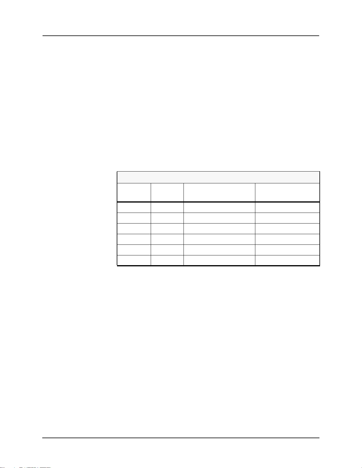
L-PRO 4000 Firmware/Software Compatibility Guide
L-PRO
Firmware
v2.3 404 v2.3 or greater 2.0
v2.2 404 v2.3 or greater 2.0
v2.1a 403 v2.1 or greater 0.0
v2.1 403 v2.1 or greater n/a
v2.0 402 v2.0 or greater n/a
v1.0 401 v1.0 or greater n/a
Setting
Version
Compatible Offliner Settings ICD File Version
Please contact ERLPhase Customer Service for complete Revision History.
D02706R02.30 L-PRO 4000 User Manual xi


PC System Requirements and Software Installation
Hardware
The minimum hardware requirements are:
• 1 GHz processor
• 2 GB RAM
• 20 GB available hard disk space
• USB port
• Serial communication port
Operating System
The following software must be installed and functional prior to installing the
applications:
• Microsoft Windows XP Professional Service Pack 3 or
• Microsoft Windows 7 Professional Service Pack 1 32-bit or 64-bit
Relay Control Panel requires Windows XP SP3 (it will not work on earlier versions of Windows).
Software Installation
The CD-ROM contains software and the User Manual for the L-PRO Transmission Line Protection Relay.
Software is installed directly from the CD-ROM to a Windows PC. Alternatively, create installation diskettes to install software on computers without a
CD-ROM drive.
The CD-ROM contains the following:
• L-PRO Offliner Settings: Offliner settings program for the relay
• L-PRO Firmware: Firmware and installation instructions
• L-PRO User Manual: L-PRO manual in PDF format
• L-PRO Function Logic Diagram: diagram in PDF format
• Relay Control Panel: software
• Relay Control Panel User Manual: manual in PDF format
• USB Driver
To Install Software on the Computer
Insert the CD-ROM in the drive. The CD-ROM should open automatically. If
the CD-ROM does not open automatically, go to Windows Explorer and find
the CD-ROM (usually on D drive). Open the ERLPhase.exe file to launch the
CD-ROM.
D02706R02.30 L-PRO 4000 User Manual xiii

PC System Requirements and Software Installation
To install the software on the computer, click the desired item on the screen.
The installation program launches automatically. Installation may take a few
minutes to start.
To view the L-PRO User Manual the user must have Adobe Acrobat on the
computer. If a copy is needed, download a copy at www.adobe.com.
Anti-virus/Anti-spyware Software
If an anti-virus/anti-spyware software on your local system identifies any of
the ERLPhase applications as a “potential threat”, it will be necessary to configure your anti-virus/anti-software to classify it as “safe” for its proper operation. Please consult the appropriate anti-virus/anti-spyware software
documentation to determine the relevant procedure.
xiv L-PRO 4000 User Manual D02706R02.30

1 Overview
1.1 Introduction
The L-PRO 4000 provides easy-to-use, state-of-the-art comprehensive distance and directional line protection for medium to extra-highvoltage transmission lines using communication-based schemes. It provides control,
automation, metering, monitoring, fault oscillography, dynamic swing recording, event logging with advanced communications in a flexible cost effective
package.
The primary protection is line protection with 5 zones of phase and ground distance functions – user-defined Mho or Quadrilateral shapes and communications based schemes (i.e. teleprotection or pilot schemes).
To provide a complete package of protection and control the relay supplies other functions such as:
• 1.0 to 1.3 cycle operation at 80% reach, ideal for EHV transmission line
• Ring bus capability – breaker failure and individual breaker monitoring
• 4-shot recloser with dead line/dead bus control and sync check
applications
• Single pole and three pole trip and reclose
• 24 statements of ProLogic addresses special protection needs
• Power Swing Blocking / Tripping
• Load Encroachment
• Switch On To Fault function
• VT Supervision function
• CT Supervision function
• Over / Under Voltage functions
• 8 Setting Groups (SG) with setting group logic
• Back up Directional overcurrent and earth fault protection
• Over / Under / Rate of change of frequency devices
Relay Control Panel (RCP) is the Windows graphical user interface software
tool provided with all 3000, 4000 series and higher (new generation) ERL relays to communicate, retrieve and manage records, event logs, fault logs, manage settings (identification, protection, SCADA etc.,), display real time
metering values, view, analyze, and export records in COMTRADE format.
In addition to the protection functions the relay provides fault recording (96
samples/cycle) to analyze faults and to review the operation of the overall protection scheme. The relay also has low speed swing recording which can be
used to analyze system stability. The triggers for fault recording are established
D02706R02.30 L-PRO 4000 User Manual 1-1

1 Overview
by programming the output matrix and allowing any internal relay function or
any external input or any GOOSE messaging input to initiate recording.
Bus 2
CT
52-1
CT
Line
52-2
50
LS
50
LS
PT
50
BF
50
BF
79-1,3
79-1,3
PL
6 Analog
Current
Inputs
Optional I/O
Rec.
21P 21N 68 50/67 51/67
Σ
Rec.
Rec.
5 Zones 5 Zones
9 External
Inputs
11 External
Inputs
14 Output Contacts
1 Relay Inoperative
Alarm Contact
7 Output Contacts
Figure 1.1: L-PRO Relay Function Line Diagram
50LS: Low set overcurrent
PL: ProLogic
WI: Weak infeed
Bus 1
50N/6751N/
27 59 60 WI Rec.
59N
CTS
Swing Recording
Positive Sequence Voltage
Positive Sequence Current
System Frequency
Real Power
Reactive Power
46/50
46/51
/67
67
60
81
/67
5050N
/67
Dead
Line
Pickup
25/27
Rec.
/59
Fault Recording
6 Voltages
12 Currents
Protection Elements
External Inputs
Active Setting Group
Output Contacts
Rec.
PT
59 27
1-2 L-PRO 4000 User Manual D02706R02.30

1.2 Front View
RELAY FUNCTIONAL
IRIG-B FUNCTIONAL
SERVICE REQUIRED
TEST MODE
ALARM
100BASE-T
(119) (150)
USB
RELAY FUNCTIONAL
IRIG-B FUNCTIONAL
SERVICE REQUIRED
TEST MODE
ALARM
100BASE-T
(119) (150)
USB
1 Overview
2
L-PRO
1
LINE PROTECTION RELAY
X
1. Front display of time, alarms and relay target
2. LEDs indicating status of relay
3. USB Port 150 for maintenance interface
4
4. Push buttons to manipulate information on settings, display and to clear targets
5. 11 Target Programmable LEDs
6. Ethernet Port 119
Figure 1.2: L-PRO Relay Front View (3U)
1
2
3
5
6
L-PRO
LINE PROTECTION RELAY
X
1. Front display of time, alarms and relay target
4
2. LEDs indicating status of relay
3. USB Port 150 for maintenance interface
4. Push buttons to manipulate information on settings, display and to clear targets
5. 11 Target Programmable LEDs
6. Ethernet Port 119
Figure 1.3: L-PRO Relay Front View (4U)
5 6
3
D02706R02.30 L-PRO 4000 User Manual 1-3

1 Overview
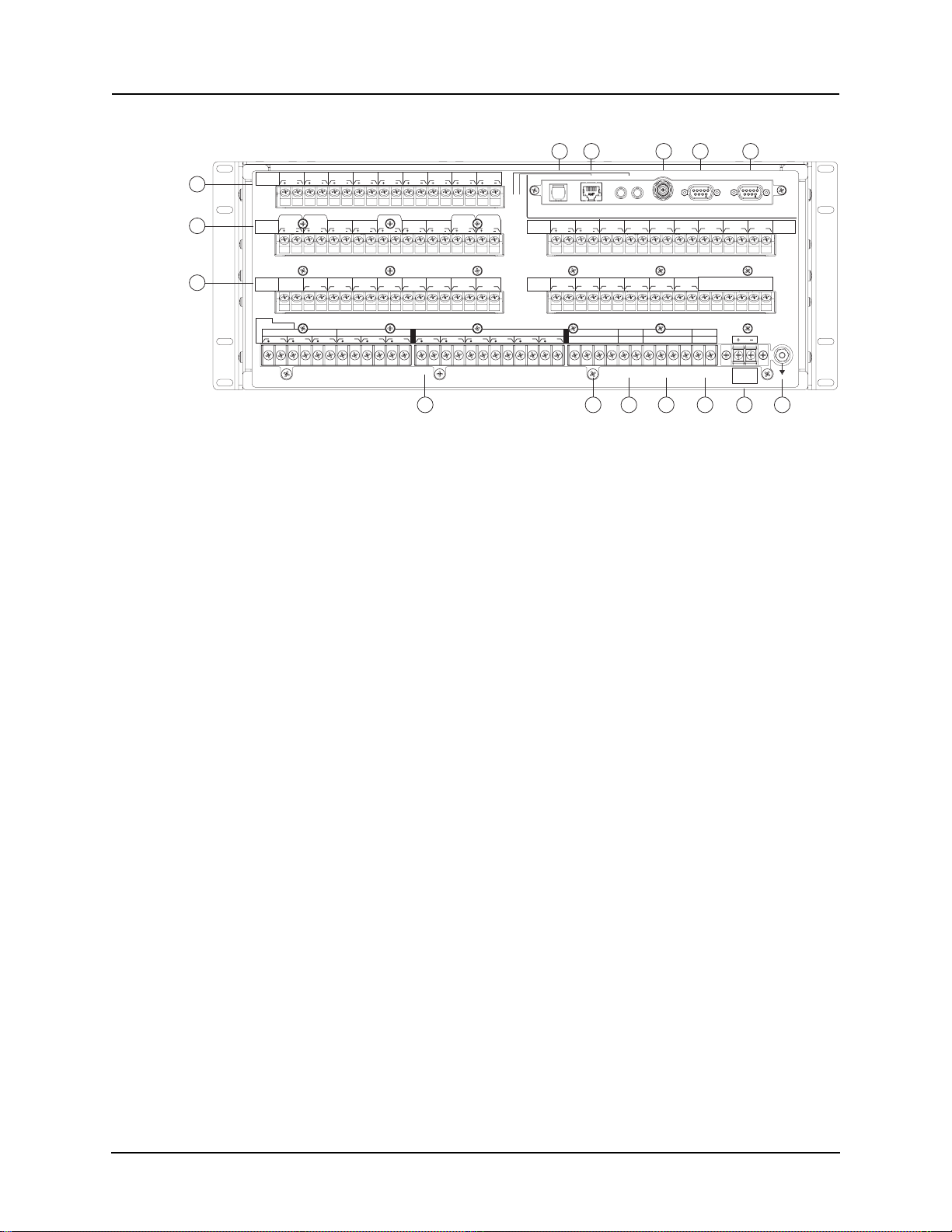
1.3 Rear View
15
91310 11
48 125 250V48 125 250V48 125 250V48 125 250V48 125 250V48 125 250V48 125 250V48 125 250V48 125 250
7
8
External
Inputs
123456789
100 101 102 103 104 105 106 107 108 109 110
NCNO
Output
Contacts
Input
1A
Main AC Line Currents
I
300 312 324
Made in Canada
NCNO
RELAY
INOPERATIVE
1
200 218201 219202 220203 221204 222205 223206 224207 225208 226209 227210 228
50Hz5A 60Hz
1A
1B
1C
I
I
301 313 325302 314 326303 315 327304 316 328305 317 329306 318 330307 319 331308 320 332309 321 333310 322 334
NO
NCNO
3
2
Aux. AC Line Currents
2A
2B
I
I
NO
4
2C
I
113
111 112
NO
NO
67
5
211 229
212 230213 231214 232215 233216 234217 235
AC Current Inputs (Record Only)
3A
I
I
311 323 335
114
NO NO
3B
V
116
117
115
3C
I
Output
Contacts
8
4A
4B
I
I
119 120
118
100BASE-
Modem
1000BASE-
NO NO NO NO NO NO
9
10
Aux. AC Volts Main AC Volts
VA VAVB VBVC VCNN
4C
I
RXRX TXTX
FXT
FXT
100BASE-
LXTX
LXTX
1000BASE-
12
11
Unused Unused
14
12
121
122 123
IRIG-B SCADA COM
13
14 18
Unused
14
Power Supply
±10%
48 to 250 Vdc
100 to 240 Vac
336
337
16
17
8
7. Ports 100-117: 9 External Programmable Inputs
8. Ports 200-201: Relay inoperative contact
Ports 202-229: 14 programmable output contacts
Ports 230-235: Unused
9. Port 118: Internal modem
10.Port 119-120: 100BASE-T or 100BASE-FX Ethernet Ports
11.Port 121: External clock, IRIG-B modulated or unmodulated
12.Port 122: SCADA
13.Port 123: Direct/Modem RS-232 Port
14.Ports 324-327, 330-333: AC voltage inputs
15.Ports 300-323: AC current inputs
16.Ports 230-235, 328, 329, 334, 335: Unused
17.Ports 336-337: Power supply
18.Port with GND symbol: Chassis Ground
Figure 1.4: L-PRO Relay Rear View (3U)
1-4 L-PRO 4000 User Manual D02706R02.30
1 Overview
13
8129 10
48 125 250V48 125 250V48 125 250V48 125 250V48 125 250V48 125 250V48 125 250V48 125 250V48 125 250
External
Inputs
7
7
123456789
100 101 102 10 3 104 105 106 107 10 8 109 110
48 V
48 V
125 V
125 V
48 125 250V48 125 250
250 V
External
Inputs
Output
Contacts
Input
1A
Made in Canada
250 V
400 418401 419402 420403 421404 422405 423406 424407 425
RELAY
1
INOPERATIVE
200 218201 219202 220203 221204 222205 223206 224207 225208 226209 227210 228
50Hz5A 60Hz
Main AC Line Currents
I1A I 2A I3A I 4AI1B I 2B I3B I 4BI1C I2C I 3C I4C
301 313 325302 314 326303 315 327304 316 328305 317 329306 318 33030 7 319 331
300 312 324
48
125
V
250
14
408 426409 427
NO NO
NCNONCNONCNO
34
2
Aux. AC Line Currents
308 320 332309 321 333
310 322 334
113
111 112
V
V
48 125 250V48 125 250
V
V
15 16 17 18
410 428
413 431
411 429412 430
NO
NO
67
5
211 229
212 230213 231214 232215 233216 234217 235
AC Current Inputs (Record Only)
311 323 335
V
116
114
117
115
48 V
48 V
125 V
125 V
250 V
250 V
External
Inputs
416 434
414 432
417 435
415 433
NO NO
Output
Contacts
8
119 120
118
100BASE-
Modem
1000BASE-
48 125 250V48 125 250
19 2010 11 12 13
NO NO NO NO NO NO
9
10
Aux. AC Volts Main AC Volts
VA VAVB VBVC VCNN
RXRX TXTX
FXT
FXT
100BASE-
LXTX
LXTX
1000BASE-
V
NONO NO NO NC NO NC NO NC NO NC
1615
12
11
Unused Unused
14 15 16
11
121
122 123
IRIG-B SCADA COM
18 19 20
17
13
Unused
14
Power Supply
±10%
48 to 250 Vdc
100 to 240 Vac
336
1817 2019
Output
Contacts
21
337
7. Ports 100-117, 400-421: 20 External Programmable Inputs
8. Port 118: Internal modem
9. Port 119-120: 100BASE-T or 100BASE-FX Ethernet Ports
10.Port 121: External clock, IRIG-B modulated or unmodulated
11.Port 122: SCADA
12.Port 123: Direct/Modem RS-232 Port
13.Port 200-229, 422-435: 21 programmable output contacts
14.Port 324-327: AC voltage inputs
15.Port 328-329: unused
16.Port 330-333: AC voltage inputs
17.Port 334-335: unused
18.Port 336-337: Power supply
19.Port 300-323: AC current inputs
20.Port with GND symbol: Case ground
Figure 1.5: L-PRO Relay Rear View (4U)
AC Current and Voltage Inputs
The relay is provided with terminal blocks for up to 12 ac currents and 6 phaseto-neutral voltages.
Each of the current input circuits has polarity (•) marks.
A complete schematic of current and voltage circuits is shown, for details see
“AC Schematic Drawings” in Appendix I and “DC Schematic Drawings”
in Appendix J.
External Inputs The relay contains 9 (3U) or 20 (4U) programmable external inputs.
Output Relay
The relay has 14 (3U) or 21 (4U) programmable relay contacts.
Contacts
Relay
Inoperative
If the relay is in self check program or becomes inoperative, then the Relay Inoperative Alarm output contact closes and all tripping functions are blocked.
Alarm Output
D02706R02.30 L-PRO 4000 User Manual 1-5

1 Overview
1.4 Model Options/Ordering
The relay is available as a horizontal mount, for details see “Mechanical Drawings” in Appendix G.
The relay is available with an optional internal modem card.
The two rear Ethernet ports can be ordered as one copper-one optical port or
both optical ports or both copper ports. These ports on the rear panel are available as either 100BASE-T (RJ-45) or 100BASE-FX (optical ST).
The Current Transformer (CT) inputs are 1 A nominal or 5 A nominal.
The external inputs are 48, 110/125 or 220/250 Vdc.
The system base frequency is either 50 Hz or 60 Hz.
The L-PRO 4000 is available in a standard 3U rack model or as 4U model with
an optional I/O board as described above.
All of the above options must be specified at the time of ordering.
1-6 L-PRO 4000 User Manual D02706R02.30

2 Setup and Communications
2.1 Introduction
This chapter discusses setting up and communicating with the relay including
the following:
• Power supply
• Inter-Range Instrumentation Group time codes (IRIG-B) time input
• Communicating with the relay using a network link, a direct serial link and
a modem link (internal, external)
• Using Relay Control Panel to access the relay’s user interface
• Using HyperTerminal to access the relay’s maintenance menu
• Setting the Baud rate
• Accessing the relay’s Supervisory Control And Data Acquisition (SCADA)
services
2.2 Power Supply
A wide range power supply is standard. The nominal operating range is 48 –
250 Vdc, 100 – 240 Vac, +/-10%, 50/60 Hz. To protect against a possible short
circuit in the supply use an inline fuse or circuit breaker with a 5 A rating. Ensure that the chassis is grounded for proper operation and safety.
There are no power switches on the relay. When the power supply is connected, the relay starts its initialization process. See “Using the IED (Getting Started)” on page 3-1 for the start up process details.
Case Grounding
Ground the relay to the station ground using the case-grounding terminal at the
back of the relay, for details see Figure 1.5: L-PRO Relay Rear View (4U) on
page 1-5.
WARNING!
Ground the relay to station ground using the case-grounding terminal
at the back of the relay, for details see Figure 1.5: L-PRO Relay Rear
View (4U) on page 1-5.
2.3 IRIG-B Time Input
The relay is equipped to handle modulated or unmodulated GPS satellite time
IRIG-B signals. The IRIG-B time signal is connected to the BNC connection
on the back of the relay. When the IRIG-B signal is provided to the relay the
IRIG-B functional Light-Emitting Diode (LED) comes on and the relay clock
D02706R02.30 L-PRO 4000 User Manual 2-1

2 Setup and Communications
is referenced to this signal. No settings are required to differentiate between
modulated or unmodulated signals; this is automatically detected by the relay.
Enable or disable the IEEE 1344 extension in the Relay Control Panel. The enabled mode allows the year to be received from the IRIG-B signal. If the available IRIG-B signal has no year extension, this setting should be disabled.
2.4 Communicating with the Relay Intelligent Electronic Device (IED)
Connect to the relay to access its user interface and supervisory control and
data acquisition (SCADA) services by:
• Front USB 2.0 interface (maintenance)
• 1 front and 2 rear Ethernet network links (user interface and SCADA)
• Direct serial link (user interface and SCADA)
• External or internal modem link (user interface only)
The relay has a front panel USB( Port 150) and 1 front Port 119 and 1 rear panel
Ethernet port 119 and 1 rear panel Ethernet Port 120 and 2 rear serial Ports 122
and 123) to provide direct access to its user interface and SCADA services.
The relay’s user interface is accessed through the Relay Control Panel.
2-2 L-PRO 4000 User Manual D02706R02.30

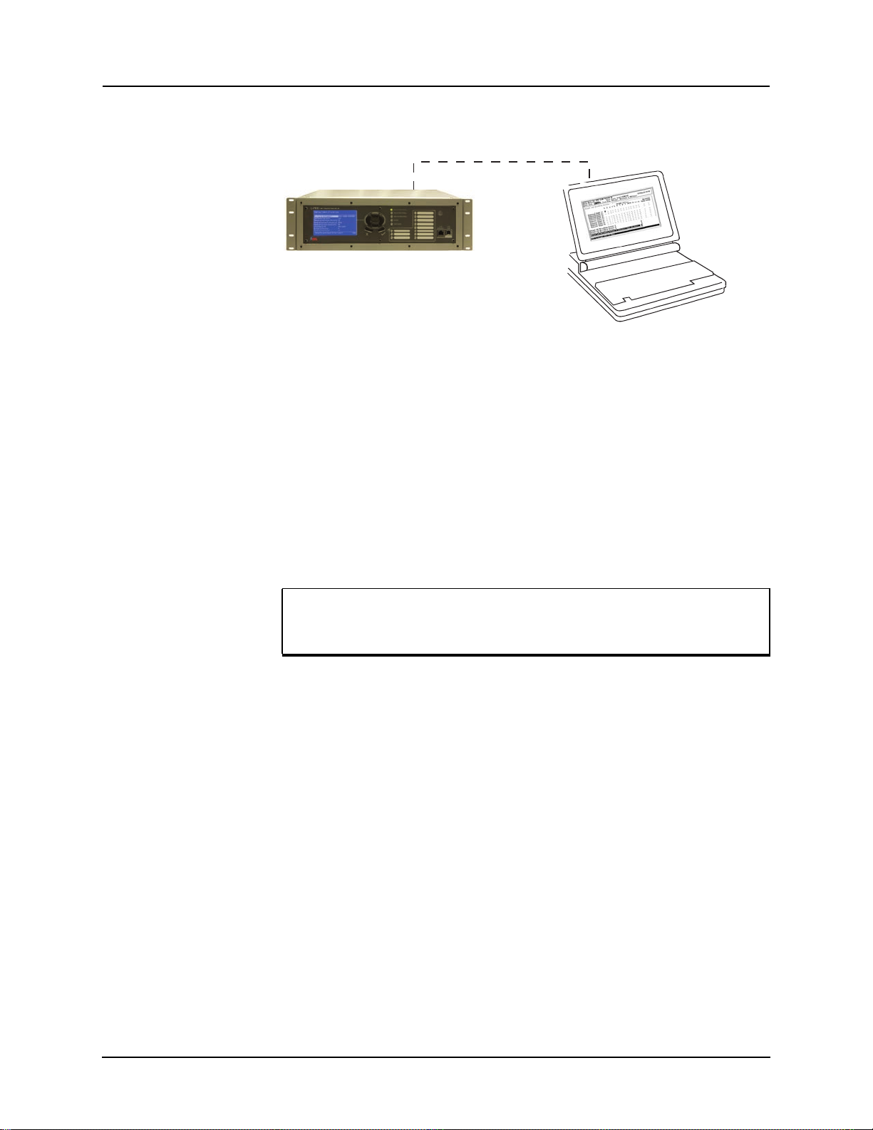
2.5 USB Link
2 Setup and Communications
The PC must be appropriately configured for USB communication.
Port 150 - USB
Laptop PC
Figure 2.1: USB Link
USB Driver Installation
To create an USB link between the relay and the computer, first the USB driver
for the ERLPhase 4000 series device needs to be installed, as follows:
Unzip the file (can be obtained from ERL website):
ERLPhase_USB_driver.zip
In this case we assume you unzipped to the desktop.
In Windows XP or Windows 7
Connect a USB port of the PC to Port 150 (USB front) of the LPRO-4000.
The LPRO-4000 was already powered on.
In the window
“Welcome to the Found New Hardware Wizard”
“Can Windows connect to Windows Update to search for software?”
Check the option “No, not this time”.
In the window
“This wizard helps you install software for:”
“ERLPhase 4000 Series Device”
“What do you want the wizard to do?”
Check the option “Install from a list or specific location (Advanced)”.
In the window
“Please choose your search and installation options”
“Search for the best driver in these locations”
D02706R02.30 L-PRO 4000 User Manual 2-3

2 Setup and Communications
Uncheck the option “Search removable media (floppy, CD-ROM.)”.
Check the option “Include this location in the search”.
Browse for the following folder:
C:\WINDOWS\tiinst\TUSB3410
In the window
“Hardware Installation”
“The software you are installing for this hardware”
“ERLPhase 4000 Series Device”
“has not passed Windows Logo testing to verify its compatibility with
Windows XP” or “Windows can’t verify the publisher”
Hit Continue Anyway.
In the window
“Completing the Found New Hardware Wizard”
“The wizard has finished installing the software for”
“ERLPhase 4000 Series Device”
Hit Finish.
To verify the installation was successful, and to which comm port is the ERLPhase 4000 Series Device configured, do the following:
In Windows XP
Start > Control Panel->Performance and Maintenance->System >Hardware > Device Manager > Ports
or (if using Control Panel’s Classic View)
Start > Control Panel > System > Hardware >Device Manager >Ports
In Windows 7 ‘small icons’ view, go to
Start>Control Panel>Device Manager>Ports.
Look for the port number associated to this device.
“ERLPhase 4000 Series Device”
Look for a COM#, where “#” can be 1, 2, 3, etc. Leave the default settings
for this port.
It is recommended to restart the PC after the USB driver installation.
The default baud rate for the relay USB Port 150 is 115200, however to double
check it login to the relay display and go to:
Main Menu > System > Relay Comm Setup
2-4 L-PRO 4000 User Manual D02706R02.30

2.6 Network Link
Figure 2.2: Network Link
Access both the relay’s user interface and DNP3 SCADA services simultaneously with the Ethernet TCP/IP LAN link through the network ports Port 119
and Port 120. The rear Port 119 and 120 are either 100BASE-T copper interface with an RJ-45 connector or 100BASE-FX optical interface with an ST
style connector. Each port is factory configurable as a copper or optical interface. The front Port 119 is 100BASE-T copper interface with an RJ-45 connector.
PC with TCP/IP
TCP/IP
Network
2 Setup and Communications
Port 119 or Port 120
Port 119 - RJ-45
Network
DNP3 SCADA services can also be accessed over the LAN, for details see
“Communication Port Details” on page 2-15.
Connect to the Ethernet LAN using a Cat 5 cable with an RJ-45 connector or
100BASE-FX 1300 nm, multimode optical fiber with an ST style connector.
By default, the Port 119 is assigned with an IP address of 192.168.100.80 Port
120 is assigned with an IP address of 192.168.101.80. If this address is not suitable, it may be modified using the relay’s Maintenance Menu. For details see
“Using HyperTerminal to Access the Relay’s Maintenance Menu” on page 2-
9.
D02706R02.30 L-PRO 4000 User Manual 2-5
2 Setup and Communications
2.7 Direct Serial Link
Port 150 - USB
Port 123 - Serial
Figure 2.3: Direct Serial Link
To create a serial link between the relay and the computer, connect the computer’s serial port and Port 123 on the relay’s rear panel provided the port is
not configured for modem use.
The serial ports are configured as EIR RS-232 Data Communications Equipment (DCE) devices with female DB9 connectors. This allows them to be connected directly to a PC serial port with standard straight-through male-to
female serial cable, for pin-out details see “Communication Port Details” on
page 2-15. Rear Port 122 is for SCADA and Port 123 can be used for direct serial access and external modem.
Laptop PC
Ensure the relay port and the PC’s port have the same baud rate and
communications parameter, see “Maintenance Menu Commands”
on page 2-11.
2-6 L-PRO 4000 User Manual D02706R02.30

2.8 Modem Link
External
2 Setup and Communications
Analog
Port 123 - RJ-11 modem
Figure 2.4: External Modem Link
Telephone
Line
Telephone
System
Analog
Telephone
Line
Desktop Computer
Using an external modem, access the relay’s user interface through a telephone
link between the relay and the computer.
Connect the serial port on the external modem to the Port 123 on the relay’s
rear panel. Both devices are configured as RS-232 DCE devices with female
connectors, so the cable between the relay and the modem requires a crossover
and a gender change. Alternatively, use the ERLPhase modem port adapter
provided with the relay to make Port 123 appear the same as a PC’s serial port.
A standard modem-to-PC serial cable can then be used to connect the modem
and the relay. For pin-out details see “Communication Port Details” on page 2-
15.
Connect the modem to an analog telephone line or switch using a standard RJ11 connector.
Configure the relay’s Port 123 to work with a modem. Log into the relay
through Relay Control Panel, go to Utilities>Communication and select port
123. Set the Baud Rate as high as possible – most modems handle 57,600 bps.
The Initialize setting allows the user to set the control codes sent to the modem
at the start of each connection session. The factory defaults are:
“M0S0=0&B1” for an external modem and “M0S0=0” for an internal modem.
D02706R02.30 L-PRO 4000 User Manual 2-7

2 Setup and Communications
Internal
Port 118 - RJ-11 modem
Analog
Telephone
Line
Telephone
System
Analog
Telephone
Line
Desktop Computer
Figure 2.5: Internal Modem Link
Access the relay’s user interface through a telephone link between the relay
and the computer using an optional internal modem. If the modem has been installed, Port 118 on the rear panel is labelled “INTERNAL MODEM.”
Connect the relay’s Port 118 to an analog telephone line or switch using a standard RJ-11 connector.
When an internal modem is installed, the relay’s Port 118 is used to interface
to the modem internally. Appropriate Port 118 settings are configured at the
factory when the internal modem is installed. The factory defaults are:
“M0S0=0&B1” for an external modem and “M0S0=0” for an internal modem.
2-8 L-PRO 4000 User Manual D02706R02.30

2 Setup and Communications
2.9 Using HyperTerminal to Access the Relay’s Maintenance Menu
This section describes how to configure a standard Windows VT-100 terminal
program on the PC for use with the relay.
The computer must be connected to the relay via the front USB port 150.
The relay is accessed using a standard VT-100 terminal style program on the
computer, eliminating the need for specialized software. Any terminal program
that fully supports VT-100 emulation and provides z-modem file transfer services can be used. HyperTerminal, which is included in Windows XP and is
also available separately as HyperTerminal PE, is used here as an example.
Configure the terminal program as described in Table 2.1:Terminal Program
Setup and link it to the appropriate serial port, modem or TCP/IP socket on the
computer.
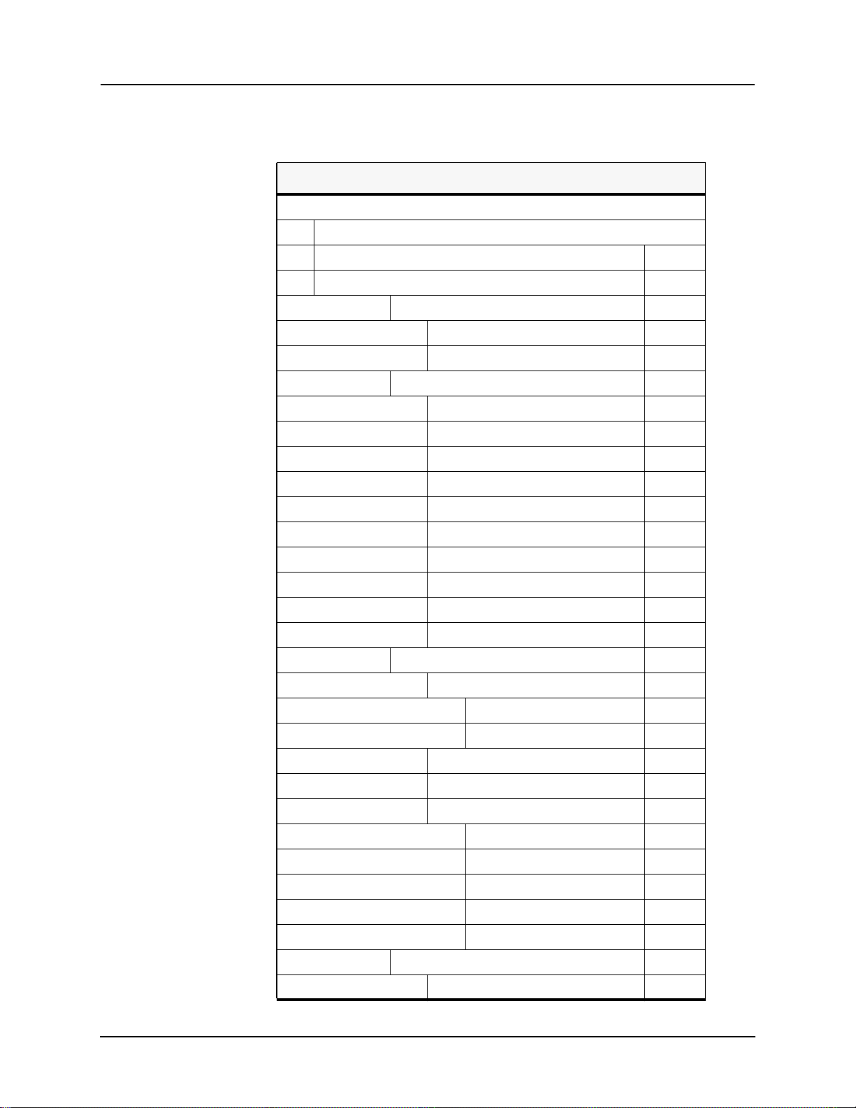
Table 2.1: Terminal Program Setup
Baud rate Default fixed baud rate 115,200 N81 (no parity, 8 data bits, 1 stop bit).
Data bits 8
Parity None
Stop bits 1
Flow control Hardware or Software.
Hardware flow control is recommended. The relay automatically supports both on all its serial ports.
Function, arrow
and control keys
Emulation VT100
Font Use a font that supports line drawing (e.g. Terminal or MS Line Draw).
Terminal keys
If the menu appears outlined in odd characters, the font selected is not
supporting line drawing characters.
To configure HyperTerminal follow these instructions:
In Windows 7 open HyperTerminal PE; in Windows XP go to
Start > All Programs > Accessories > Communications > HyperTerminal
If “Default Telnet Program?” windows pops up,
Check “Don’t ask me this question again”
Hit No.
First time use of HyperTerminal will ask for “Location Information”.
Fill with appropriate information, e.g.:
“What country/region are you in now”
Choose “Canada”
D02706R02.30 L-PRO 4000 User Manual 2-9

2 Setup and Communications
“What area code (or city code) are you are in now?”
Enter “306”
“If you need to specify a carrier code, what is it?”
Enter “”, i.e. leave blank
“If you dial a number to access an outside line, what is it?”
Enter “”.
“The phone system at this location uses:”
Choose “Tone dialing”.
Hit OK.
First time use of HyperTerminal will show “Phone and Modem Options”.
Hit Cancel.
HyperTerminal will show initially “Connection Description”.
Enter a name for the relay, e.g: “LPRO4000”.
Hit OK.
In the window “Connect To”
“Connect using”
Choose “COM#”, where “#” was obtained previously in Section 2.5 USB
Link, after installing the USB driver.
Let’s assume in this case it is COM3.
In the window “COM3 Properties” choose:
“115200”
“8”
“None”
“1”
“Hardware”
Hit Apply then hit OK
At this time the connection should already be established.
Hit Enter in the terminal window.
2-10 L-PRO 4000 User Manual D02706R02.30

Login as maintenance in lower case.
Figure 2.6: Maintenance Menu
2 Setup and Communications
Maintenance Menu Commands
Commands 1, 4, 5, 6 and 7 are Port 150 access only.
Table 2.2: Maintenance Menu Commands
Modify IP address
View system diagnostic
Retrieve system diagnostics
Restore settings (commands 4, 5 and 6)
Force hardware reset
Modifies the LAN IP addresses, network mask, default gateway
and IEC61850 network port assignment.
Displays the internal status log.
Automatically packages up the internal status log plus setting
and setup information and downloads it in compressed form to
the computer. This file can then be sent to our customer support
to help diagnose a problem.
Use these commands to force the system back to default
values, if a problem is suspected due to the unit's settings,
calibration and/or setup parameters.
Manually initiates a hardware reset. Note that the
communication link is immediately lost and cannot be
reestablished until the unit completes its start-up.
Network utilities
Monitor SCADA
D02706R02.30 L-PRO 4000 User Manual 2-11
Enters network utilities sub-menu.
Shows real time display of SCADA data.

2 Setup and Communications
Table 2.3: Network Utilities Menu Commands
View protocol statistics View IP, TCP and UDP statistics
View active socket states View current states of active sockets
View routing tables View routing tables
Ping Check network connection to given point
Exit network utilities Exit network utilities menu and return to Maintenance Menu
2.10 Firmware Update
The relay has an update login that can be accessed by a connection through a
VT100 terminal emulator (such as HyperTerminal). This login is available
only from Port 150.
1. Use the terminal program to connect to Port 150.
2. Select Enter, the terminal responds with a login prompt.
3. Login as update in lower case.
Commands
The firmware update is used to update the relay’s software with maintenance
or enhancement releases. Please see the L-PRO Firmware Update Procedure
documentation that comes with the firmware update for instructions on how to
update the firmware on the relay.
2-12 L-PRO 4000 User Manual D02706R02.30

2.11 Setting the Baud Rate
The baud rate is available on the LCD screen from the top level menu
selecting System then Relay Comm Setup.
2 Setup and Communications
Direct Serial Link
For a direct serial connection, both the relay and the computer must be set to
the same baud rate.
To change the baud rate of a relay serial port:
1. The user needs to log into the relay as Change (any port) or Service (USB
port only) using RCP.
2. Then choose Utilities>Communication tab.
Modem Link Unlike a direct serial link, the baud rates for a modem link do not have to be
the same on the computer and on the relay. The modems automatically negotiate an optimal baud rate for their communication.
The baud rate set on the relay only affects the rate at which the relay communicates with the modem. Similarly, the baud rate set in HyperTerminal only affects the rate at which the computer communicates with its modem. Details on
how to set these respective baud rates are described above, except that the user
modifies the Port 123 baud rate on the relay and the properties of the modem
in HyperTerminal.
D02706R02.30 L-PRO 4000 User Manual 2-13

2 Setup and Communications
2.12 Accessing the Relay’s SCADA Services
The relay supports DNP3 (Level 2) and Modbus SCADA protocols as a standard feature on all ERLPhase relays. DNP3 is available through a direct serial
link or the Ethernet LAN on top of either TCP or UDP protocols. The Modbus
implementation supports both Remote Terminal Unit (RTU) binary or ASCII
modes and is available through a direct serial link.
The relay’s Port 122 is dedicated for use with Modbus or DNP3 serial protocols. Port 122 uses standard RS-232 signalling. An external RS-232<->RS-485
converter can also be used to connect to an RS-485 network.
For details on connecting to serial Port 122 see “Communicating with the Relay Intelligent Electronic Device (IED)” on page 2-2 and “Communication
Port Details” on page 2-15.
The DNP3 protocol can also be run across the Ethernet LAN. Both DNP over
TCP and DNP over UDP are supported. For details on connecting to the Ethernet LAN see “Network Link” on page 2-5.
Complete details on the Modbus and DNP3 protocol services can be found in
the Appendices, for details see “Modbus RTU Communication Protocol”
in Appendix E and “DNP3 Device Profile” in Appendix F
Protocol Selection
Communication Parameters
To select the desired SCADA protocol go to L-PRO 4000 Offliner SCADA
communications section. Select the protocol and set the corresponding parameters.
Port 122’s communication parameters are set in the L-PRO 4000 Offliner
SCADA communications section Both the baud rate and the parity bit can be
configured. The number of data bits and stop bits are determined automatically
by the selected SCADA protocol. Modbus ASCII uses 7 data bits. Modbus
RTU and DNP Serial use 8 data bits. All protocols use 1 stop bit except in the
case where either Modbus protocol is used with no parity; this uses 2 stop bits,
as defined in the Modbus standard.
Diagnostics Protocol monitor utilities are available to assist in resolving SCADA commu-
nication difficulties such as incompatible baud rate or addressing. The utilities
can be accessed through the Maintenance Menu Commands, see “Maintenance
Menu Commands” on page 2-11
2-14 L-PRO 4000 User Manual D02706R02.30

2.13 Communication Port Details
Table 2.4: Communication Port Details
Location Port Function
Front Panel 119 RJ-45 receptacle, 100BASE-T Ethernet interface. Default IP =
192.168.100.80
Used for user interface access or SCADA access through Ethernet LAN.
Front Panel 150 USB-B receptacle, High speed USB 2.0 interface
Used for user interface access
Default fixed baud rate 115,200 N81 (no parity, 8 data bits, 1 stop
bit).
Rear Panel 118 RJ-11 receptacle, Internal modem interface.
Default Baud rate 38,400 N81 (no parity, 8 data bits, 1 stop bit)
Rear Panel 119 Rear panel, RJ-45 receptacle or ST type optical receptacle (fac-
tory configured). 100BASE-T or 100BASE-FX (1300nm, multimode) Ethernet interface. Same subnet as front panel port 119.
Used for user interface access or IEC61850/DNP SCADA access
through Ethernet LAN.
2 Setup and Communications
Rear Panel 120 ST type optical receptacle. 100BASE-FX (1300 nm, multimode)
Ethernet interface.
Used for user interface access or IEC61850/DNP SCADA access
through Ethernet LAN
Rear Panel 121 BNC receptacle, IRIG-B Interface. Modulated or un-modulated,
330 ohm impedance.
Rear Panel 122 RS-232 DCE female DB9.
Used for SCADA communication.
Default Setting: 19,200 baud O71 (odd parity, 7 data bits, 1 stop)
Rear Panel 123 RS-232 DCE female DB9.
Used for:
• User interface access through a direct serial connection.
• Default Setting: 9600 baud N81 (no parity, 8 data bits, 1
stop bit).
• User interface access through an external modem. The
optional ERLPhase Modem Adapter converts this port to a
Data Terminal Equipment (DTE) to simplify connection to
an external modem.
D02706R02.30 L-PRO 4000 User Manual 2-15

Table 2.5: Signal connections to pins on Relay Port
Signal Name
DCD 1
RxD 2
TxD 3
DTR 4
Common 5
DSR 6
RTS 7
CTS 8
No connection 9
Notes:
Relay is DCE, PC is DTE.
Pins 1 and 6 are tied together internal to the relay.
Direction PC<-> Relay Pin # on the Relay Port
Table 2.6: Cable Pin Connections
Male DB-9 Cable End for Relay Port Female DB-9 Cable End for Computer Port
Pin # on Cable Pin # on Cable
11
22
33
44
55
66
77
88
99

2 Setup and Communications
Table 2.7: Signal name connections to pins on Modem Adapter
Signal Name Direction Modem <-> Relay Pin # on the Modem Adapter
DCD 1
RxD 2
TxD 3
DTR 4
Common 5
DSR 6
RTS 7
CTS 8
No connection 9
Notes:
Relay (with modem adapter) is DTE, modem is DCE.
Pins 1 and 6 are tied together internal to the relay.
D02706R02.30 L-PRO 4000 User Manual 2-17


3 Using the IED (Getting Started)
3.1 Introduction
This section provides information on the start-up sequence and ways to interface with the relay. Descriptions of the Front Panel Display, Terminal Mode
and Metering Data are provided.
3.2 Start-up Sequence
When the power supply is connected, the following initialization initializing
sequence takes place:
Table 3.1: Initialization Sequence
TEST MODE — red LED on when power applied
RELAY FUNCTIONAL — green LED on within 5 seconds after power applied
TEST MODE — red LED off then on within 10 seconds
Front Display — on on within 20 seconds after power applied
TEST MODE — red LED off within 20 seconds after power applied
When the Relay Functional LED comes on, it indicates that the DSP is actively
protecting the system.
When the test mode LED goes off, the relay is capable of recording and communicating with the user.
3.3 Interfacing with the Relay
The following ways can be used to interface with the relay:
• Front panel display
• Terminal mode (for maintenance and firmware upgrade)
• Relay Control Panel
D02706R02.30 L-PRO 4000 User Manual 3-1

3 Using the IED (Getting Started)
3.4 Front Panel Display
The front panel display is the fastest and easiest way of getting information
from the relay.
Display 16 LED Lights
LED Lights
6 Push Buttons
USB Port 150
Ethernet Port 119
Figure 3.1: Front Panel Display
The display, the 16 LED lights and the 6 push buttons, provide selective information about the relay.
Table 3.2: Description of LED Lights
Relay Functional Indicates when the relay is functional. When the Relay Functional
green LED goes on, the rear Relay Inoperative contact changes to
an open and the protective functions become functional.
IRIG-B Functional
Service Required Indicates the relay needs service. This LED can be the same state
Indicates the presence of a valid IRIG-B time signal where the LED
is on.
as the Relay Functional LED or can be of the opposite state
depending on the nature of the problem.
The following items bring up this LED:
• DSP failure - protection difficulties within the relay.
• Communication failure within the relay.
• Internal relay problems.
Test Mode Occurs when the relay output contacts are intentionally blocked.
Possible reasons are:
• Relay initialization on startup
• User interface processor has reset and is being tested.
The user cannot communicate with the relay through the ports until
the front display becomes active and the TEST MODE LED goes
out. Normally, the red Target LED remains off after this start-up
unless the relay had unviewed target messages.
Alarm Occurs when an enabled relay function picks up.
The red Alarm LED should be off if there are no inputs to the relay.
If the Alarm LED is on, check the event log messages which are
available through the menu system.
3-2 L-PRO 4000 User Manual D02706R02.30

Table 3.2: Description of LED Lights
Target LED Number Description (Default values)
3 Using the IED (Getting Started)
1
2
3
4
5
6
7
8
9
10
11
Any device 21P trip operation (phase distance - 21P1, 21P2, 21P3,
21P4)
Any device 21N trip operation (ground distance - 21N1, 21N2,
21N3, 21N4)
Any device 50 or 51 trip operation (phase overcurrent - 50 or 51,
neutral overcurrent - 50N or 51N, negative sequence overcurrent
46-50 or 46-51)
Any device 50BF trip operation (breaker failure - 50BF Main-1,
50BF Main-2, 50BF Aux-1, 50BF Aux-2)
Any device 81 trip operation (over/under-frequency - 81-1, 81-2, 813, 81-4)
Switch On To Fault trip operation
Communication Scheme trip operation
Device 68 trip operation Power Swing trip
ProLogic 1 - 8
ProLogic 9 - 16
ProLogic 17 - 24
Push Buttons
Target LED assignments are the default values but are configurable
by the user through the Offliner settings (output matrix configuration).
Table 3.3: Identification of Push Buttons
Up, Down, Right, Left, Enter, Escape
Used to navigate the front panel screens.
D02706R02.30 L-PRO 4000 User Manual 3-3
3 Using the IED (Getting Started)
Display The basic menu structure for navigation of the LCD screen is given below:
Table 3.4: Navigation of the LCD Screen
Main Screen
View / Change / Service : Choice Menu
Enter Password
Main Menu (V)
System (V)
Relay Identification (V)
Relay Comm Setup (V)
Settings
System Parameters
Record Length
Setting Group 1
Setting Group 2
Setting Group 3
Setting Group 4
Setting Group 5
Setting Group 6
Setting Group 7
Setting Group 8
Metering (V)
Analog (V)
Analog Inputs (V)
Line Quantities (V)
External Inputs (V)
Output Contacts (V)
Logic (V)
Logic Protections 1 (V)
Logic Protections 2 (V)
ProLogic (V)
Group Logics (V)
Virtual Inputs (V)
Records (V)
View Record List (V)
3-4 L-PRO 4000 User Manual D02706R02.30
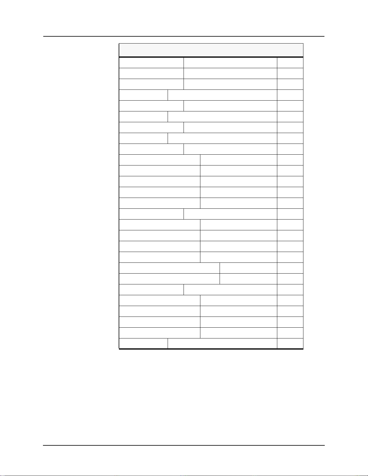
Table 3.4: Navigation of the LCD Screen
Fault Recording (C,S)
Swing Recording
Event Recording
Fault Log
Fault List
Event Log (V)
Event List
Utilities (V)
Setup (V)
Timeouts (V)
Time Settings (V)
Set Manual Time (V)
Set DST Time (V)
External Inputs (V)
3 Using the IED (Getting Started)
Maintenance (V)
Output Contacts Control (S)
Virtual Inputs Control (C,S)
Setting Groups Control (C,S)
Erase (C,S)
Erase Records (C,S)
Erase Event Logs (C,S)
Network (V)
Network Protocol Stats (V)
Active Sockets (V)
Routing Tables (V)
Ping (V)
Logout (V)
Where the access levels required to access each are indicated by:
V: view
C: change
S: service
To login into the LCD menu structure, follow these steps:
D02706R02.30 L-PRO 4000 User Manual 3-5
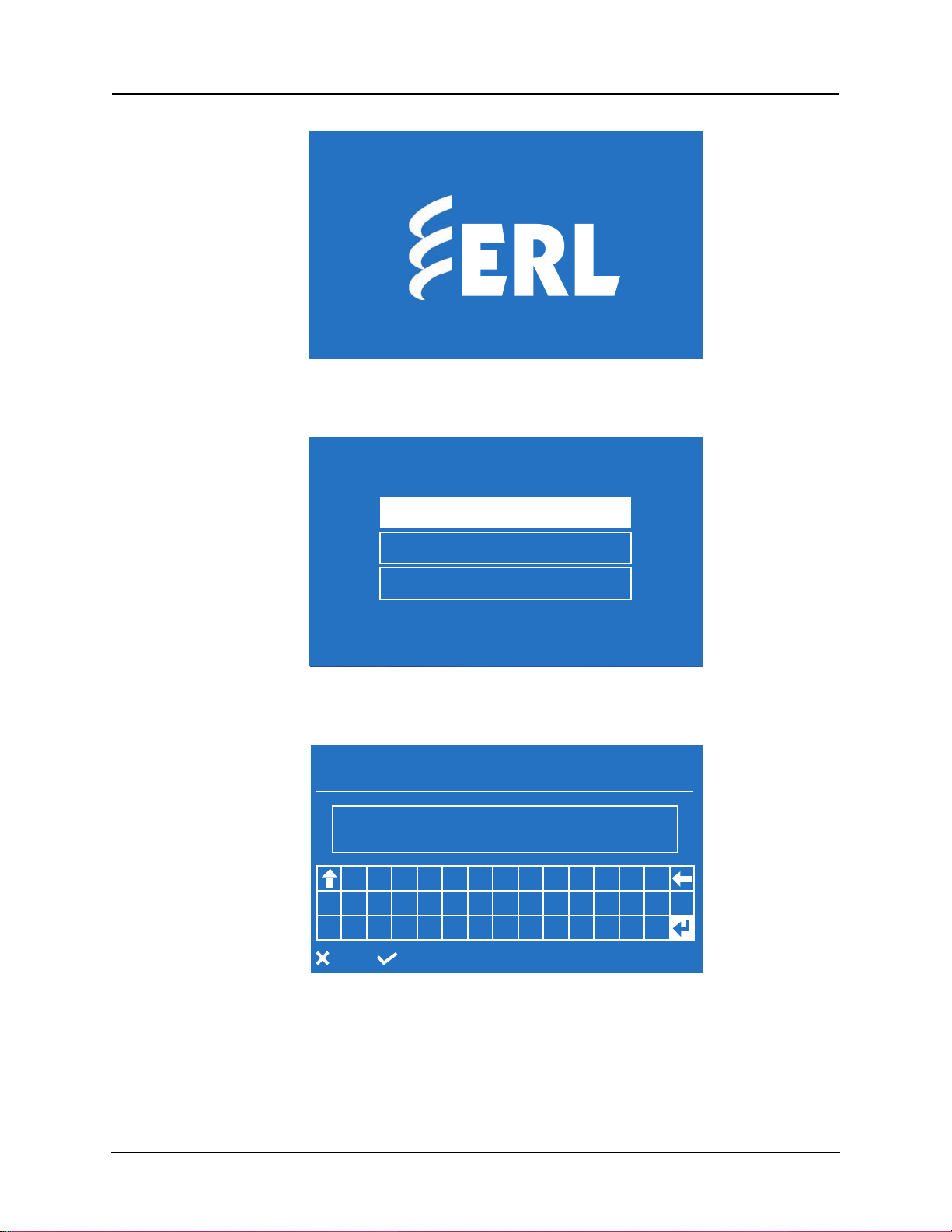
3 Using the IED (Getting Started)
2012Oct24
12:17
LPRO-4000-101224-01
Figure 3.2: Main Screen
ERLPhase LPRO 4000
2011Aug06
21:48:54
View
Change - read/write
Service - full access
*passwords are case sensitive
*logins have an activity timeout of:
Figure 3.3: View / Change / Service: Choice Menu
Enter Password
60mins
2011Aug06
21:48:54
****
1 2 3 4 5 6 7 8 9 0 - + =
a b c d e f g h i j k l m n o
Sp p q r s t u v w x y z , .
back
Figure 3.4: Enter Password
3-6 L-PRO 4000 User Manual D02706R02.30
select view

3 Using the IED (Getting Started)
Main Menu
2011Aug06
21:48:54
System
Settings
Metering
Records
Fault Log
Event Log
Utilities
Logout
select view
Figure 3.5: Main Menu
In the Main Screen, hit Enter.
In the View / Change / Service: Choose Menu screen, choose desired access
level, hit Enter.
In the Enter Password screen, enter appropriate password, hit Enter on the return character (right bottom one)
The Main Menu screen should appear.
Note: The default passwords are (remove quotation marks)
View Access “view”
Change Access “change”
Service Access “service”
3.5 Terminal Mode
The terminal mode is used to access the relay for maintenance functions see
“Using HyperTerminal to Access the Relay’s Maintenance Menu” on page 29 and “Firmware Update” on page 2-12.
3.6 Relay Control Panel
RCP is used for all user interface. A short description of the RCP configuration
to connect to a relay is given here. Please refer to the Relay Control Panel User
Manual for details.
Follow this sequence to configure RCP for USB link to the relay.
1. Execute.
Relay Control Panel.exe
2. Execute.
L-PRO 4000 Offliner.exe
3. Install Null Modem Driver.
D02706R02.30 L-PRO 4000 User Manual 3-7

3 Using the IED (Getting Started)
Please refer to the Relay Control Panel User Manual for details.
4. Run Relay Control Panel.
Go to:
Start > All Programs > ERLPhase > Relay Control Panel > Relay Control
Panel
First time RCP is run.
Hit Add New.
“Add New Relay”
Choose Communication > Direct Serial Link.
Hit Get Information From Relay.
Then RCP will communicate with the LPRO-4000 and retrieve information to fill required fields.
When this is done, hit Save Relay.
If the window “Relay already exists...” pops up, you may need to rename the relay changing the “Relay Name” in the “Relay Definition”
category, before saving.
After first time, in “Select Relay”, choose relay and hit Connect.
In “Relay Password Prompt”
Choose desired access level, enter appropriate password
Note: Default passwords are listed below (remove the quotation
marks)
View Access “view”
Change Access “change”
Service Access “service”
The basic structure of the Relay Control Panel information, including basic
actions available, is given below:
Table 3.5: Relay Control Panel Structure
View Change Service
Relay Control Panel
Records Trigger Fault Trigger Fault
Trigger Swing Trigger Swing
Trigger Event Trigger Event
Faults Erase Erase
Events Erase Erase
Metering
3-8 L-PRO 4000 User Manual D02706R02.30

Table 3.5: Relay Control Panel Structure
Analog
Line
External
Logic 1
Logic 2
ProLogic
Outputs
Group Logic
Virtual
Utilities
Unit Identification
Communication
Time
3 Using the IED (Getting Started)
Analog Input Calibration N/A N/A
External Input
Virtual Inputs N/A Latch/Pulse Latch/Pulse
Toggle Outputs N/A N/A Close/Open
Settings Group Save Save
Passwords N/A N/A
Configuration
Present Settings (Get From
Relay)
Saved Settings (Load to
Relay)
(Load to
Relay)
Notice that some options are not available (N/A) depending on the access level.
D02706R02.30 L-PRO 4000 User Manual 3-9


4 Protection Functions and
Specifications
Introduction ...... page 4-2
Protection and Recording Functions ...... page 4-2
21P Phase/21N Ground Distance ...... page 4-2
Load Encroachment (LE) ...... page 4-5
Relay Method of Memory Polarization ...... page 4-8
Relay Method of Memory Polarization ...... page 4-8
Ring Filter ...... page 4-9
Directional Element ...... page 4-10
Directional Element Outputs ...... page 4-12
21P and 21N Phase Selector ...... page 4-13
Capacitance Coupled Voltage (CCVT) Transformer on 21 Devices ...... page
4-16
68 Power Swing ...... page 4-17
Line Energization Supervision Logic ...... page 4-19
Switch On To Fault (SOTF) ...... page 4-20
Weak Infeed (WI) ...... page 4-22
25/27/59 Sync Check ...... page 4-23
79 Recloser ...... page 4-24
Summary of Trip and Reclose Schemes ...... page 4-28
59 Main/Auxiliary Overvoltage ...... page 4-28
...... page 4-28
60 Loss of Potential (LOP) ...... page 4-31
81 Frequency ...... page 4-34
50LS Overcurrent ...... page 4-35
50BF Breaker Failure ...... page 4-36
50/51/67 Phase Overcurrent ...... page 4-38
50N/51N/67 Neutral Overcurrent ...... page 4-40
46-50/46-51/67 Negative Sequence Overcurrent ...... page 4-41
Adaptive Additional Delay for 50 O/C Elements ...... page 4-42
Z Circle Trigger ...... page 4-43
Fault Locator ...... page 4-43
ProLogic ...... page 4-44
Group Logic ...... page 4-45
Communication-Aided Scheme ...... page 4-47
50/51N OC Carrier Start and Block Logic ...... page 4-47
Basic Logic ...... page 4-48
POTT Logic ...... page 4-49
DCB Logic ...... page 4-50
PUTT Logic ...... page 4-51
Recording Functions ...... page 4-51
Introduction ...... page 4-51
Fault Recording ...... page 4-51
Swing Recording ...... page 4-52
D02706R02.30 L-PRO 4000 User Manual 4-1

4 Protection Functions and Specifications
Event Recording ...... page 4-52
Record Initiation ...... page 4-52
Record Duration and Extension ...... page 4-53
Record Storage ...... page 4-53
Record Retrieval and Deletion ...... page 4-53
Event Log ...... page 4-54
Fault Log ...... page 4-55
4.1 Protection and Recording Functions
Introduction This section describes the equations and algorithms of the relay protection
functions. All functions with time delay provide an alarm output when their
pickup level is exceeded.
The following functions are exceptions: 27 Auxiliary, 27 Main, 59 Auxiliary,
59 Main, 25/27/59 Sync Check, 50LS Main, 50LS Auxiliary, 50BF Main,
50BF Auxiliary, 81 Frequency and ProLogic elements.
A complete list of the settings and their range values can be found in “IED Settings and Ranges” in Appendix B.
21P Phase/21N Ground Distance
The relay 21P contains 5 zones of phase distance elements; all 5 zones of 21P
can be set to either Mho or Quadrilateral type. Note that only one type can be
used at a time. The 21P can contain a mixture of Mho and Quadrilateral shapes,
for example the 21P1 and 21P2 can be set to a Mho characteristic and the 21P3,
21P4 and 21P5 could be set to a Quadrilateral characteristic.
The relay 21N contains 5 zones of ground distance elements; all 5 zones of 21N
can be set to either Mho or Quadrilateral type. Note that only one type can be
used at a time. The 21N can contain a mixture of Mho and Quadrilateral
shapes, for example the 21N1 and 21N2 can be set to a Mho characteristic and
the 21N3, 21N4 and 21N5 could be set to a Quadrilateral characteristic.
The Quadrilateral shape is parallel to the positive sequence line angle setting.
The user-defined Mho Characteristic Angle is not selectable when a Quadrilateral characteristic for that particular zone is defined. All other settings are selectable and user-definable.
Zones 3, 4 and 5 reach can be set in either forward direction or reverse direction
or offset as required. All the distance functions are set in secondary ohms. The
available range of impedance settings is based on the nominal current specified
when the relay was ordered. The impedance reach ranges are given in “21P
Phase/21N Ground Distance” on page 4-2.
4-2 L-PRO 4000 User Manual D02706R02.30

Line Z1
X
Zone 4
X
Zone 5
Zone 3
Zone 2
Characteristic Angle
Zone 1
Line Angle
4 Protection Functions and Specifications
R
Figure 4.1: Phase and Ground distance protection Mho relay characteristic
The shape of the phase and ground distance relays is adjustable. For the circular Mho characteristic shape, the characteristic angle is 90 degrees. Determine
this angle by drawing 2 lines from any point on the impedance locus to the diameter of the characteristic. Produce a tomato-shaped characteristic by selecting an angle less than 90 degrees or a lens-shaped characteristic with angles
greater than 90 degrees.
X
Zone 5
Zone 3
Zone 2
Zone 1
Line Z1
Forwa rd
Line Angle
Zone 4
R
Directional Element
Reverse
Figure 4.2: Phase and Ground distance protection Quadrilateral Characteristics
The shape of the Mho characteristic means that significant extensions are made
to the relay characteristics in the R region of the R-X plane for ground faults.
D02706R02.30 L-PRO 4000 User Manual 4-3

4 Protection Functions and Specifications
A
V
B
0
K
Restrict the reach in the R region for the phase distance relays where load encroachment is an issue. The shaped Mho characteristic provides the best fit for
the application keeping the number of relay settings at a minimum and provides the benefits associated with the Mho characteristic.
The Mho characteristic used by the relay is developed by the classical approach using the measurement of the angle between 2 vectors.
These vectors are defined as:
(1)
(2)
(3)
=
phase
IZ
set
V
ref
Ko3I
–=
+
where
V is the actual line voltage for ground distance relays or the actual line to
line voltage for the phase distance relay.
I is defined as above for ground distance relays or the line to line current for
phase distance relays.
Z
is the setting reach and V
set
is a positive sequence memory voltage
ref
stored within the relay.
V
is the polarizing quantity for the Mho elements, and is more completely
ref
described in “Relay Method of Memory Polarization” on page 4-8.
To make the reach of the ground distance relay relate to the line positive sequence impedance the classical K
factor is used.
o
This factor is defined as
(4)
0
Z0Z1–
=
-----------------3Z
1
The relay includes a directional element to supervise the phase (21P) and
ground (21N) Mho elements, for all five Zones (21P1 to 21P5 and 21N1 to
21N5). The directional element improves security of the Mho elements for reverse faults such as: bus faults, phase-phase faults during high load conditions.
The directional element does not supervise Zone 3, Zone 4 and Zone 5 elements if these zones are set as offset characteristic. The directional element is
described in “Directional Element” on page 4-10.
4-4 L-PRO 4000 User Manual D02706R02.30

4 Protection Functions and Specifications
Load Encroachment (LE)
Line angle
Circle (90°)
Figure 4.3: Mho Characteristic Shapes
Line angle
Tomato (<90°)
Line angle
Lens (>90°)
The load impedance may enter into the protection zones permanently or temporarily due to system condition. This is observed in very long lines or heavily
loaded medium lines will have issue. This is a normal load conditions and it is
not an abnormal/fault conditions. Therefore, the relay should not initiate any
trip command during this condition. The relay should identify properly whether the impedance entered into the protection zone is normal load condition or
fault condition.
This is distinguished by monitoring all phase-to-phase impedance values (i.e.
Zab, Zbc & Zca).If all the three phase impedances enter into the protection
zones with the limited load angle area, it is declared as a loading condition and
21P function is blocked. If only one of the phase-to-phase impedance enters
into the protection zones with the limited load angle area then this can be declared as fault condition.
Generally, the three phase fault will not have any additional resistance component other than the conductor resistance. Therefore, three phase fault will always have the fault angle as close to line angle only and it will not enter into
the loading area.
Figure 4.4: Load Encroachment (LE) Logic on page 4-5 shows how the LE
function works. Phase-to-phase current monitoring has been added to the logic
to ensure stable operation.
Figure 4.4: Load Encroachment (LE) Logic
D02706R02.30 L-PRO 4000 User Manual 4-5

4 Protection Functions and Specifications
Table 4.1: 21P Phase Distance Element Settings
Zone 1 Zone 2 Zone 3 Zone 4 Zone 5
Enable/ Disable
Characteristic Type Mho / Quadri-
lateral
Forward Impedance
Reach (Ohms secondary)
Forward Reactance
Reach (Ohms secondary)
Reverse Impedance
Reach (Ohms secondary)
Reverse Reactance
Reach (Ohms secondary)
Left Reach (R1) (Ohms
secondary)
0.00 to 66.00
(5A)
0.00 to
330.00 (1A)
0.00 to 66.00
(5A)
0.00 to
330.00 (1A)
0.05 to 66.00
(5A)
0.25 to
330.00 (1A)
Enable/ Disable
Mho / Quadrilateral
0.00 to 66.00
(5A)
0.00 to
330.00 (1A)
0.00 to 66.00
(5A)
0.00 to
330.00 (1A)
0.05 to 66.00
(5A)
0.25 to
330.00 (1A)
Enable/ Disable
Mho / Quadrilateral
0.00 to 66.00
(5A)
0.00 to
330.00 (1A)
0.00 to 66.00
(5A)
0.00 to
330.00 (1A)
0.00 to 66.00
(5A)
0.00 to
330.00 (1A)
0.00 to 66.00
(5A)
0.00 to
330.00 (1A)
0.05 to 66.00
(5A)
0.25 to
330.00 (1A)
Enable/ Disable
Mho / Quadrilateral
0.00 to 66.00
(5A)
0.00 to
330.00 (1A)
0.00 to 66.00
(5A)
0.00 to
330.00 (1A)
0.00 to 66.00
(5A)
0.00 to
330.00 (1A)
0.00 to 66.00
(5A)
0.00 to
330.00 (1A)
0.05 to 66.00
(5A)
0.25 to
330.00 (1A)
Enable/ Disable
Mho / Quadrilateral
0.00 to 66.00
(5A)
0.00 to
330.00 (1A)
0.00 to 66.00
(5A)
0.00 to
330.00 (1A)
0.00 to 66.00
(5A)
0.00 to
330.00 (1A)
0.00 to 66.00
(5A)
0.00 to
330.00 (1A)
0.05 to 66.00
(5A)
0.25 to
330.00 (1A)
Both
Quadrilateral
Both
Quadrilateral
Quadrilateral
Right Reach (R2) (Ohms
secondary)
Mho Characteristic Angle
(degrees)
Pickup Delay (seconds) 0.00 to 99.00 0.00 to 99.00 0.00 to 99.00 0.00 to 99.00 0.00 to 99.00 Both
Id Supervision (A secondary)
Line Angle (degrees) 5.0 to 89.0
Load Impedance (Ohms)
R (Ohms secondary) -150.0 to 150.0 Both
X (Ohms secondary) -150.0 to 150.0 Both
Load Encroachment Enable/Disable Both
LHS
Impedance (Ohms secondary)
0.05 to 66.00
(5A)
0.25 to
330.00 (1A)
70.0 to 140.0 70.0 to 140.0 70.0 to 140.0 70.0 to 140.0 70.0 to 140.0 Mho
0.2 to 50.0
(5A) 0.04 to
10.00 (1A)
Setting is made in Line Parameters (Positive Sequence Angle)
0.01 to 66.0 (5 A)
0.05 to 330.0 (1 A)
0.05 to 66.00
(5A)
0.25 to
330.00 (1A)
0.2 to 50.0
(5A) 0.04 to
10.00 (1A)
0.05 to 66.00
(5A)
0.25 to
330.00 (1A)
0.2 to 50.0
(5A) 0.04 to
10.00 (1A)
0.05 to 66.00
(5A)
0.25 to
330.00 (1A)
0.2 to 50.0
(5A) 0.04 to
10.00 (1A)
0.05 to 66.00
(5A)
0.25 to
330.00 (1A)
0.2 to 50.0
(5A) 0.04 to
10.00 (1A)
Quadrilateral
Both
Both
4-6 L-PRO 4000 User Manual D02706R02.30

4 Protection Functions and Specifications
Table 4.1: 21P Phase Distance Element Settings
Upper angle (degrees) 90.1 to 179.9 Both
Lower angle (degrees) 180.1 to 269.9 Both
RHS
Impedance (Ohms secondary)
Upper angle (degrees) 0.1 to 89.9 Both
Lower angle (degrees) -0.1 to -89.9 Both
0.01 to 66.0 (5 A)
0.05 to 330.0 (1 A)
Both
Table 4.2: 21N Ground Distance Element Settings
Zone 1 Zone 2 Zone 3 Zone 4 Zone 5
Enable/ Disable
Characteristic Type Mho / Quadri-
lateral
Forward Impedance
Reach (Ohms secondary)
Forward Reactance
Reach (Ohms secondary)
0.00 to 66.00
(5A)
0.00 to
330.00 (1A)
0.00 to 66.00
(5A)
0.00 to
330.00 (1A)
Enable/ Disable
Mho / Quadrilateral
0.00 to 66.00
(5A)
0.00 to
330.00 (1A)
0.00 to 66.00
(5A)
0.00 to
330.00 (1A)
Enable/ Disable
Mho / Quadrilateral
0.00 to 66.00
(5A)
0.00 to
330.00 (1A)
0.00 to 66.00
(5A)
0.00 to
330.00 (1A)
Enable/ Disable
Mho / Quadrilateral
0.00 to 66.00
(5A)
0.00 to
330.00 (1A)
0.00 to 66.00
(5A)
0.00 to
330.00 (1A)
Enable/ Disable
Mho / Quadrilateral
0.00 to 66.00
(5A)
0.00 to
330.00 (1A)
0.00 to 66.00
(5A)
0.00 to
330.00 (1A)
Both
Quadrilateral
Reverse Impedance
Reach (Ohms secondary)
Reverse Reactance
Reach (Ohms secondary)
Left Reach (R1) (Ohms
secondary)
Right Reach (R2) (Ohms
secondary)
Mho Characteristic Angle
(degrees)
Pickup Delay (seconds) 0.00 to 99.00 0.00 to 99.00 0.00 to 99.00 0.00 to 99.00 0.00 to 99.00 Both
D02706R02.30 L-PRO 4000 User Manual 4-7
0.05 to 66.00
(5A)
0.25 to
330.00 (1A)
0.05 to 66.00
(5A)
0.25 to
330.00 (1A)
70.0 to 140.0 70.0 to 140.0 70.0 to 140.0 70.0 to 140.0 70.0 to 140.0 Mho
0.05 to 66.00
(5A)
0.25 to
330.00 (1A)
0.05 to 66.00
(5A)
0.25 to
330.00 (1A)
0.00 to 66.00
(5A)
0.00 to
330.00 (1A)
0.00 to 66.00
(5A)
0.00 to
330.00 (1A)
0.05 to 66.00
(5A)
0.25 to
330.00 (1A)
0.05 to 66.00
(5A)
0.25 to
330.00 (1A)
0.00 to 66.00
(5A)
0.00 to
330.00 (1A)
0.00 to 66.00
(5A)
0.00 to
330.00 (1A)
0.05 to 66.00
(5A)
0.25 to
330.00 (1A)
0.05 to 66.00
(5A)
0.25 to
330.00 (1A)
0.00 to 66.00
(5A)
0.00 to
330.00 (1A)
0.00 to 66.00
(5A)
0.00 to
330.00 (1A)
0.05 to 66.00
(5A)
0.25 to
330.00 (1A)
0.05 to 66.00
(5A)
0.25 to
330.00 (1A)
Both
Quadrilateral
Quadrilateral
Quadrilateral

4 Protection Functions and Specifications
R
X
Line Z
Source Z
No Memory
Voltage
Full
Memory
Voltage
Table 4.2: 21N Ground Distance Element Settings
Id Supervision (A secondary)
3I0 Supervision (A secondary)
Line Angle (degrees) 5.0 to 89.0
Load Impedance (Ohms)
R (Ohms secondary) -150.0 to 150.0 Both
X (Ohms secondary) -150.0 to 150.0 Both
Relay Method of Memory Polarization
0.2 to 50.0
(5A) 0.04 to
10.00 (1A)
0.2 to 50.0
(5A) 0.04 to
10.00 (1A)
Setting is made in Line Parameters (Positive Sequence Angle)
0.2 to 50.0
(5A) 0.04 to
10.00 (1A)
0.2 to 50.0
(5A) 0.04 to
10.00 (1A)
0.2 to 50.0
(5A) 0.04 to
10.00 (1A)
0.2 to 50.0
(5A) 0.04 to
10.00 (1A)
0.2 to 50.0
(5A) 0.04 to
10.00 (1A)
0.2 to 50.0
(5A) 0.04 to
10.00 (1A)
0.2 to 50.0
(5A) 0.04 to
10.00 (1A)
0.2 to 50.0
(5A) 0.04 to
10.00 (1A)
The 21P and 21N Mho/Quad elements use positive-sequence voltage, derived
from a memory voltage, as the polarizing quantity. No user settings are required for the memory polarization functionality. Sufficient positive-sequence
voltage should be available during all fault events. However, during certain
fault events, especially 3-phase bolted faults near the line VT location, the positive-sequence voltage may be insufficient for correct operation. To ensure adequate positive-sequence voltage exists for all fault conditions, the relay uses
a ring filter, implemented in software, to provide memory voltage as the source
for the positive-sequence voltage. This memory voltage lasts for approximately 150 cycles, even if all voltage inputs from the line VTs go to zero. A practical effect of using a memorized voltage is to expand the Mho characteristic by
the magnitude of the source impedance see “Effect of using Memorized Voltage on a 3-phase forward fault condition” on page 4-8. This expansion of the
characteristic ensures correct operation for zero voltage faults at the relay location, and for forward capacitive faults.
Both
Both
.
4-8 L-PRO 4000 User Manual D02706R02.30
Figure 4.5: Effect of using Memorized Voltage on a 3-phase forward fault condition

4 Protection Functions and Specifications
V
A
Ring Filter
Sequence
Component
Filter
V
B
V
C
Ring Filter
Ring Filter
Vpos_mem
Sequence
Component
Filter
Vpos
Vpos_mem
correct?
Vpolarizing
Ring Filter The voltage memory in the relay uses a ring filter implemented in software.
The ring filter is a high-Q bandpass filter, with the frequency response centered
on the nominal system frequency. The effect of the ring filter is to retain some
voltage information for approximately 150 cycles, even if the measured system
voltage is severely depressed by a fault.
Figure 4.6: Polarizing Voltage
Fault
Ring Filter
Memory Voltage
Figure 4.7: Effect of the Ring Filter
The ring filter is designed to adjust the center of the frequency response to account for small variations of the power system frequency. When the measured
voltage drops below 0.5 V
, the ring filter explicitly uses the nominal system
sec
frequency as the center point of the bandpass filter. During this condition, or
when the system frequency varies widely or rapidly, as during out-of-step conditions, the ring filter could provide an incorrect output. During these conditions, the 21P and 21N Mho/Quad elements use the positive-sequence voltage
derived from the system voltage directly from the line VTs until the voltage
output of the ring filter is correct. If the measured positive sequence voltage is
below 1 Vsec, then the Mho/Quad elements use the positive sequence voltage
derived from the memory voltage
D02706R02.30 L-PRO 4000 User Manual 4-9

4 Protection Functions and Specifications
Reverse
Forward
Line Impedance
R
jX
90.0
Line Z Angle
Directional Element
The relay includes a directional element that directly supervises the Zone 1 to
Zone 5 phase and ground distance elements, the 50/51/67, 50N/51N/67N, 4650/51/67 overcurrent elements, and the 50N/67F and 50N/67R elements in the
Communications Aided Tripping schemes. The directional element considers
negative-sequence impedance, zero-sequence impedance, or positive-sequence impedance, depending on relay settings and system conditions at the
time of the fault. The element declares a forward fault when the impedance determined by the directional element is within 90° of the line impedance.
Figure 4.8: Fault Direction
The directional element in the relay is always enabled. The directional element
actually consists of 3 separate internal elements: a negative-sequence element,
a zero-sequence element, and a positive-sequence element. The negative-sequence and zero-sequence elements use directly measured currents and voltages. The positive-sequence element uses directly measured current, and a
memory voltage from the ring filter. The sensitivity for the negative- and zerosequence elements may be set by the user, to correctly account for load conditions and system configuration. Both of these elements may be disabled as
well. The positive-sequence element is always active.
4-10 L-PRO 4000 User Manual D02706R02.30
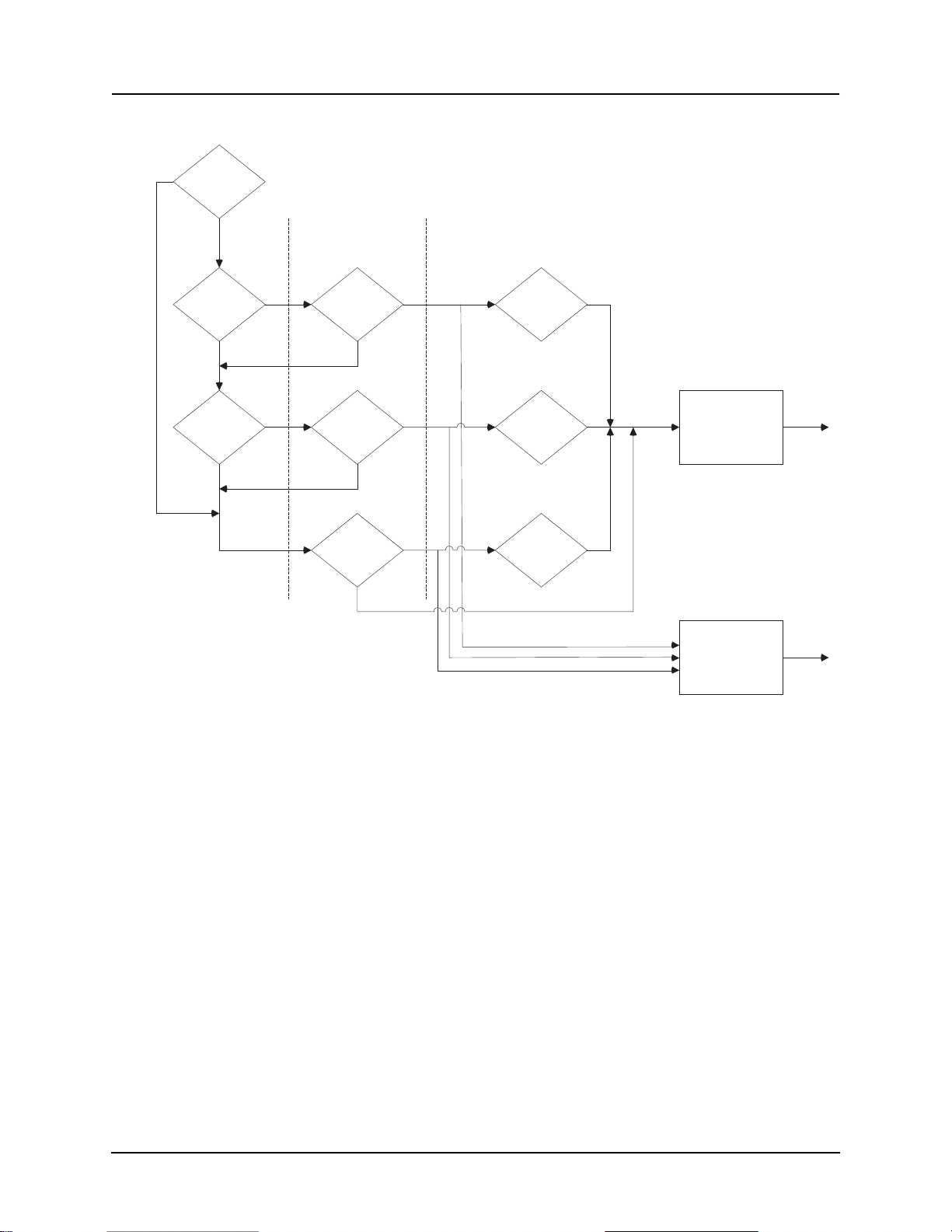
4 Protection Functions and Specifications
3P Fault
Z2
ON
Z0
ON
V2
I2
3V0
3I0
V1 (mem)
I1
Forward
Forward
Forward
Directional
Element
Asserted
Directional
Element
Valid
Y
Y
Y
Y
Y
Y
Y
Y
Y
N
N
N
N
N
N
Minimum Sensitivity
Threshold
Figure 4.9: Directional Element Logic
For 3-phase faults, the directional element will only use the positive-sequence
element. For all other faults, the directional element will consider, in order, the
negative-sequence calculation, the zero-sequence calculation, and the positivesequence calculation. The directional element will only move from one calculation to the next calculation if insufficient sequence voltages and currents exist to make a valid calculation.
The negative-sequence calculation determines the angle between the measured
negative-sequence impedance, and the positive-sequence line impedance angle
entered in settings. To perform this calculation, the default minimum amount
of negative-sequence voltage required is 0.5 V secondary, and the default minimum amount of negative-sequence current required is 0.2 A secondary.
The zero-sequence calculation determines the angle between the measured
zero-sequence impedance the zero-sequence line impedance angle entered in
settings. To perform this calculation, the default minimum amount of zero-sequence voltage (3
amount of zero-sequence current (3
) required is 1.0 V secondary, and the default minimum
V0
) required is 0.2 A secondary.
I0
D02706R02.30 L-PRO 4000 User Manual 4-11

4 Protection Functions and Specifications
Directional Element
Directional Valid
Reverse Fault
The positive-sequence calculation determines the angle between the measured
positive-sequence impedance (based on measured current, and the memory
voltage output of the ring filter) and the positive-sequence line impedance angle entered in settings. To perform the positive-sequence impedance calculation, the directly measured positive-sequence current must exceed 0.2 A
secondary, and the memorized positive-sequence voltage must exceed 2 V secondary.
There may be some rare circumstances where there may not be sufficient voltage or current, using the negative, zero, and positive sequence components, for
the directional element to make a valid directional decision. The most likely
circumstance where this may occur is a 3-phase bolted fault near the line VTs,
that is not cleared in an appropriate amount of time. It takes approximately 30
cycles, after the measured 3-phase system voltage drops to 0, for the ring filter
voltage to decay such that the Vpos_mem is less than 2 V secondary. For this
circumstance, or for any other fault case where there are insufficient sequence
component quantities for any of the directional calculations to operate, the direction is set to “forward”. Setting the directional element to forward explicitly
sets the direction to forward for the distance elements, and for the 50N/67N-F
and 50N/67N-R elements in the communications aided tripping schemes (effectively blocking the 50N/67N-R element), and allows all other directional
controlled elements to operate non-directional.
Directional Element Outputs
Directional Element Settings
The output of the directional element asserts when the direction is determined
to be “forward”. This output is used internally by protection functions directly
supervised by the element, and is also available as the “Directional Element”
indication in ProLogic equations. The directional element also provides the
“Directional Valid” output for use in ProLogic equations. This output asserts
when any one of the active sequence impedance calculations has sufficient input quantities to make a valid direction determination, regardless of the actual
direction. The “Directional Valid” output will always be asserted, except in the
rare case where system voltage has gone to 0 for more than 30 cycles, as previously described. The 2 outputs can be combined in a ProLogic equation to e
a secure reverse directional output from the relay, for example.
Figure 4.10: Directional Element
The default setting of the directional element in the relay should be correct for
most applications. The default settings enable both the negative-sequence and
zero-sequence calculations, with the minimum sensitivities as described. There
are some applications where it may be advisable to change the sensitivity
thresholds for the negative-sequence or zero-sequence calculations, or it may
be desirable to disable one or both of these elements.
Selecting “Directional Element Override Enabled” allows user settings for the
negative-sequence and zero-sequence directional elements.
4-12 L-PRO 4000 User Manual D02706R02.30

4 Protection Functions and Specifications
The settings for the negative-sequence voltage sensitivity and negative-sequence current sensitivity should be normally higher than the maximum negative sequence quantities generated by unbalanced load. These settings should
also be low enough to maintain sensitivity for the minimum unbalanced fault,
in terms of negative sequence quantities.
The zero-sequence directional element can be used in many applications. However, where strong mutual coupling between parallel lines exist, the zero-sequence calculation must be disabled to prevent an incorrect directional
determination. The sensitivity settings should be low enough to permit operation during the lowest expected ground fault in terms of zero-sequence quantities expected during a fault, and high enough to allow for normal load
imbalance.
.
Table 4.3: Directional Element Settings
Override Enabled Enable/Disable
Negative-Sequence Enable/Disable
V2 Sensitivity Level (V secondary) 0.5 to 5.0
21P and 21N Phase Selector
I2 Sensitivity Level (A secondary) 0.1 to 1.0 (5 A)
0.02 to 0.20 (1 A)
Zero Sequence Enable/Disable
3V0 Sensitivity Level (V secondary) 1.0 to 10.0
3I0 Sensitivity Level (A secondary) 0.2 to 2.0 (5 A)
0.04 to 0.40 (1 A)
The phase selector algorithm for the relay ensures that:
• 21N only trips on single-phase-to-ground fault, so as to prevent 21N from
false tripping for phase-to-phase-to-ground faults with arc resistance
• Supervise 21P for low Source Impedance Ratio (SIR) ratios and singlephase-to-ground faults at 20% of line reach or below.
Algorithm Details
The phase selector uses a combination of positive, negative and zero sequence
current phasors to correctly determine the faulty phase. No user settings are required for the phase selector functionality. An OR function with angle checks
between I
and I2 as well as the angle between I2 and I0. The OR function al-
1
lows the algorithm to adapt to various fault conditions and provide the correct
fault type. When energizing a line with a T-tapped load, the user may have system conditions where no pre-trigger load current is available. Using positive
and negative sequence currents alone may cause an incorrect fault determination if the load current is significantly large enough to affect the total positive
sequence current, which includes both load and fault current. Our algorithm
overcomes this problem.
D02706R02.30 L-PRO 4000 User Manual 4-13

4 Protection Functions and Specifications
Angle Relationship of Positive and Negative Sequence Currents
The angle comparison scheme is used to determine the faulty phase and the
fault type. If the load current is subtracted from the total current (i.e. only fault
current is left for angle comparison), the positive sequence (I
sequence (I
Table 4.4: Angular difference between positive and negative sequence
) and negative
1
) current phase angle relations are listed in the following table:
2
currents for various faults
Angle Diff. between I1A and I2A
(AngleDiff_A)
Angle Diff. between I
(AngleDiff_B)
Angle Diff. between I1C and I
(AngleDiff_C)
1B
and I
2B
2C
AG
Fault
0 120 120 180 60 60
120 0 120 60 60 180
120 120 0 60 180 60
BG
Fault
CG
Fault
BCG
Fault
ABG
Fault
CAG
Fault
Phase Selector Criteria for I1 and I2
The following criteria is used to determine the fault type and phase:
AG Fault: AngleDiff_A<45.0 and AngleDiff_B >90.0 and AngleDiff_C >90.0
BG Fault: AngleDiff_B<45.0 and AngleDiff_C >90.0 and AngleDiff_A >90.0
CG Fault: AngleDiff_C<45.0 and AngleDiff_A >90.0 and AngleDiff_B >90.0
In the above criteria only one can become true at a time. They are used to supervise 21N_A, 21N_B, 21N_C respectively.
Angle Relationship of Negative and Zero Sequence Currents
The angle comparison scheme is used to determine the faulty phase and the
fault type. The negative sequence (I
) and zero sequence (I0) current phase an-
2
gle relations are listed in the following table:
Table 4.5: Angular difference between negative and zero sequence currents
for various faults
AG
Fault
Angle Diff. between I2A and I
(AngleDiff_I2_I0_A)
Angle Diff. between I2B and I
(AngleDiff_I2_I0_B)
Angle Diff. between I2C and I
(AngleDiff_I2_I0_C)
4-14 L-PRO 4000 User Manual D02706R02.30
0 120 120 0 120 120
0
120 0 120 120 120 0
0
120 120 0 120 0 120
0
BG
Fault
CG
Fault
BCG
Fault
ABG
Fault
CAG
Fault

4 Protection Functions and Specifications
Phase Selector Criteria for I2 and I
0
The following criteria is used to determine the fault type and phase:
AG Fault: AngleDiff_I2_I0_A<25.0 degrees
BG Fault: AngleDiff_I2_I0_B<25.0 degrees
CG Fault: AngleDiff_I2_I0_C<25.0 degrees
Though AG type of fault will be declared for a BCG fault by the above angle
criteria between I
and I0, the characteristic of AG impedance prevents AG
2
from tripping because the phase selector is used for supervision only, i.e. the
phase selector is not a tripping device.
Device 21P Supervision
A 21P supervision logic is formed based on the above Phase Selector Criteria.
The phase-to-phase distance element is only allowed to operate if the faulted
phase is not involved with the element:
21P_AB Supervision = Not AG Fault and Not BG Fault
21P_BC Supervision = Not BG Fault and Not CG Fault
21P_CA Supervision = Not CG Fault and Not AG Fault
The Start of the Phase Selector
The phase selector starts only when a fault occurs. The start definition is: if 3I0
is greater than the minimum of any enabled 21N zone’s 3
supervision level
I0
setting, begin the phase selector algorithm.
A buffer is used to track the pre-trigger load current, which is subtracted from
the total current before checking the phase selector criteria.
During fault conditions the system frequency may change causing a drift in the
angle difference being calculated by the phase selector. The locked pre-trigger
load current vector is adjusted accordingly based on this angle difference between the pre-trigger positive sequence voltage and the positive sequence voltage during the fault. If the faulted positive sequence voltage shifts, the angle
difference is taken into account. (i.e. the same angle relationship remains along
the fault duration.)
Duration of the Phase Selector Supervision
The maximum blocking time to 21N for a phase-phase-ground fault is from 2.0
seconds to x seconds, where x is the maximum pickup delay in enabled 21P2
to 21P5, and then plus 8 cycles (8 cycles is the maximum breaker opening).
This ensures that if 21P did not trip on the phase-phase-ground fault for some
reason, 21N is allowed to trip on this fault after this maximum blocking time
delay has expired.
D02706R02.30 L-PRO 4000 User Manual 4-15

4 Protection Functions and Specifications
Ground Indicator in 21P Event Message
3I0 is checked against the minimum of the following settings:
Capacitance Coupled Voltage (CCVT) Transformer on 21 Devices
• 21N1: 3
• 21N2: 3
• 21N3: 3
• 21N4: 3
• 21N5: 3
supervision when it’s enabled
I0
supervision when it’s enabled
I0
supervision when it’s enabled
I0
supervision when it’s enabled
I0
supervision when its enabled
I0
• 50N Pickup level when it’s enabled
• 51N Pickup level when it’s enabled
• 50N_67F when it’s selected as Scheme_Only or both ProLogic&Scheme
When 3
exceeds the minimum of the above values, a ground indicator “G” is
I0
put in the 21P event messages, e.g. “21P Trip ABG 123.1 km”
When a fault occurs, especially on a line with high source to impedance ratio
(SIR), the CCVT secondary voltage can become quite different from the actual
system voltage varying in both magnitude and phase due to the transient response of the CCVT. This transient response can cause device 21 overreach
significantly. A special CCVT transient compensation algorithm (Patent Pending) has been included in L-PRO 4000 relay to address this issue.
The CCVT transient compensation algorithm uses a combination of techniques
with digital filters, vector averages and other means to rebuild the correct voltage from the transient distorted voltage waveforms. This combination of techniques provides a secure method for detecting and correcting CCVT transient
phenomena. On one hand, it improves the reach accuracy of 21 devices dramatically during the period of the CCVT subsidence transient. On the other
hand, it will not sacrifice the relay operation speed very much. It does not add
any additional delay when the SIR is low (<1.2). In the worst case, it adds about
one cycle delay when the SIR is high (>15). For the operation time details, refer
to “IED Specifications” in Appendix A.
This compensation algorithm can be enabled or disabled through
settings. Note that this algorithm is applied to all 21 devices once it is
enabled. For the applications without CCVTs, this compensation algorithm should be disabled so as to eliminate the possible additional
delay introduced by this algorithm.
4-16 L-PRO 4000 User Manual D02706R02.30

4 Protection Functions and Specifications
68 Power Swing The Power Swing function can be used as a tripping or blocking function. This
function consists of 2 sets of inner and outer impedance Zones on the R-X
plane, for details see If the user selects Device 68 to block for Power Swing
conditions, the relay energizes the front panel alarm LED when the 68 elements are blocking. If the user selects the 68 to trip for Power Swing conditions
the relay energizes the front panel target light. on page 4-17. Set the Power
swing zones to different values and to have the Power Swing function operate
for different system conditions. The Power swing zones are quadrilateral characteristic and the reactance lines with the same angle as the angle chosen for
the line positive sequence impedance. Outputs from the outer and the inner
power swing zones are available on the output matrix for use with other types
of Power Swing schemes or for monitoring.
X
X4
X3
Zone 5
R1R2
Zone 3
Zone 2
Line Z1
Zone 1
Line Angle
Zone 4
X2
X1
R4R3
R
Figure 4.11: Power Swing Characteristic
The basic Power Swing scheme looks at the positive sequence impedance of
the line with respect to the line loading. If the line loading causes the impedance to cross the outer Zone, an Power Swing timer is started. If the impedance
does not cross the inner zone before this timer times out, the function produces
an output (either a block or trip whichever is set) when the impedance crosses
the inner Zone. The entire activity is supervised by an overcurrent function to
prevent undesired operations for impedances far from the origin.
The logic has a timeout feature that prevents the blocking function from operating for an indefinite amount of time. Device 68 functions as either a blocking
device or tripping device. The 68 Power Swing (68 Trip or 68 Block), 68 Inner
and 68 Outer Zone logic points are available in the output matrix. These logic
points are also logged as event messages in the event log, “Event Messages”
in Appendix D In addition, the outputs from the inner and outer Zones are
available for use with ProLogic to create any application scheme required.
If the user selects Device 68 to block for Power Swing conditions, the relay energizes the front panel alarm LED when the 68 elements are blocking. If the
user selects the 68 to trip for Power Swing conditions the relay energizes the
front panel target light.
D02706R02.30 L-PRO 4000 User Manual 4-17

4 Protection Functions and Specifications
Zpos
Enable Setting
50 Ipos
50 3I0
60
X
R
TB
0
Figure 4.12: Power Swing Function
Table 4.6: 68 Power Swing Function Details
Mode Block, Off, Trip
Zone Blocking
Zone 1 Blocking Enable/Disable
Zone 2 Blocking Enable/Disable
Zone 3 Blocking Enable/Disable
Zone 4 Blocking Enable/Disable
Zone 5 Blocking Enable/Disable
Out of Step Swing Timer 0.00 to 1.00 seconds
I1 Supervision 0.5 to 50.0 A secondary (5A)
0.1 to 10.0 A secondary (1A)
Inner Blinder Alarm
Outer Blinder Alarm
68 Block
68 Trip
Out of Step
3I0 Blocking 0.5 to 50.0 A secondary (5A)
0.1 to 10.0 A secondary (1A)
Blocking Reset Time 0.25 to 2.00 seconds
Left Hand Side (LHS) Blinder
Outer (R1) -100.0 to R2 ohms secondary (5A)
-500.0 to R2 ohms secondary (1A)
Inner (R2) R1 to R3 ohms secondary
Right Hand Side (RHS) Blinder
Inner (R3) R2 to R4 ohms secondary
4-18 L-PRO 4000 User Manual D02706R02.30

Line Energization Supervision Logic
4 Protection Functions and Specifications
Table 4.6: 68 Power Swing Function Details
Outer (R4) R3 to 100.0 ohms secondary (5A)
R3 to 500.0 ohms secondary (1A)
Top Blinder
Outer (X4) X3 to 100.0 ohms secondary (5A)
X3 to 500.0 ohms secondary (1A)
Inner (X3) X2 to X4 ohms secondary
Bottom Blinder
Inner (X2) X1 to X3 ohms secondary
Outer (X1) -100.0 to X2 ohms secondary (5A)
-500.0 to X2 ohms secondary (1A)
Vpos - VposOld > 10 vol ts
VposOld < 30 volts
Ipos < 4% of Norminal Current
1 sec.
20 ms
Block al l 21 devi ces
Figure 4.13: Line Energization Supervision Logic
Note: Vpos is the present positive sequence voltage.
VposOld is the positive sequence voltage at two cycles before.
The Logic shown in “Line Energization Supervision Logic” on page 4-19 has
been introduced in order to prevent potentially erroneous operations of the 21
upon energizing of T-tapped transmission lines that have transformers connected and the PT connected on the line side of the breaker. This logic does not require any user setting.
In this logic, the present positive sequence voltage is compared with the positive sequence voltage of 2 cycles previously. In an energization situation, the
VposOld would be near zero V and the present Vpos would be approximately
the nominal. As time goes by the old Vpos gets updated with the nominal voltage and would eventually equal the present. When it gets within 10 V secondary the top input to the AND gate would reset, go to zero, and reset the blocking
function.
The second input is the previous 2 cycle positive sequence voltage and has an
undervoltage setting of 30 V. This input goes high to block the distance relays
only if the positive sequence voltage from 2 cycles back was less than 30 V
(approximately 50% nominal), so, for a line that has been previously energized
and now experiences a fault, no distance relay blocking takes place.
The third input (the bottom one) produces an output only if the positive sequence line current is less than 4% nominal or 4.0% of 5 A secondary = 0.20
D02706R02.30 L-PRO 4000 User Manual 4-19

4 Protection Functions and Specifications
A secondary. If this current has been that low for the 1 second pickup time delay this input to the AND gate would go high. For a de-energized line this input
would normally be high to allow the blocking scheme to operate if the other
two inputs are high. This input along with input two are present to help prevent
any distance relay blocking for a line that is in service and is now experiencing
a line fault.
Switch On To Fault (SOTF)
When energizing a line that has been out of service, the line may have a fault
on it. If the line potential is derived from bus PTs, the distance relay function
acts normal and operates for any fault that exists when the line is energized. If
the line uses line PTs, the output of these line PTs is zero before energizing.
Because there is no memory voltage, operation of the line distance functions
may be undefined. To provide protection to detect faults when a line is first energized, the Switch On To Fault function (SOTF) is involved.
Figure 4.14: Switch On To Fault (SOTF)
The logic diagram, Figure 4.14: Switch On To Fault (SOTF) on page 4-20,
shows how the circuit actually works. The SOTF function has options as Close
Command or Status Monitoring.
4-20 L-PRO 4000 User Manual D02706R02.30

4 Protection Functions and Specifications
Close Command
This method can be applied where the relay can get the Breaker Close command from control panel manual close switch (TNC) or SCADA Close command. This Close command should reach the relay as an External Input or a
Virtual Input or ProLogics to initiate SOTF logic.
This method ensures that all the poles or any one pole are in dead condition for
more than the A1 timer by checking the current level (i.e. lower than 4% of
nominal), then it will enable the SOTF function.
Status Monitoring
This method can be applied where the relay can get Breaker status (52A). This
Breaker Status Monitoring signal should reach the relay as an External Input
or a Virtual Input to initiate SOTF logic.
This method will monitor all the pole statuses as well as each pole load current.
The SOTF function is enabled whenever current value is changing from 0 to
more than 4% of nominal or any pole Breaker status is changing from open to
close.
Both options have a common Pick-up delay (i.e. timer B1), which will allow
to extend the SOTF function enabled up-to the desired settable duration. Typically, this timer value shall be equal to Zone 2 time delay setting.
During SOTF Enabled condition, if any 50 Trip or 50N Trip or Zone 2 (21N2
or 21P2) alarm picked up condition happens, then the relay will go for an instantaneous 3-pole SOTF Trip.
In addition to the above options, the SOTF function has a second harmonic restraint logic which allows the line to be more easily energized if the line is Ttapped with an online reactor or transformer. Energization of the line with the
T-tapped device results in second harmonics that allows the line to be energized. If a fault exists that exceeds the line high set overcurrent devices, the line
is allowed to trip.
Table 4.7: Switch On To Fault Settings
Switch On To Fault Enable/Disable
Breaker Signal Close Command/ Status Monitoring
Close Pulse EI1 to EI 20, PL1 to PL24, VI1 to VI30 (This setting shall
be enabled when the Breaker signal setting is selected
as Close Command)
Pole Dead Pick-up Timer (A1,
Pick-up timer)
Main Breaker Status EI1 to EI 20, PL1 to PL24, VI1 to VI30 (This setting shall
D02706R02.30 L-PRO 4000 User Manual 4-21
0.0 to 999.9 Seconds (This setting shall be enabled
when the Breaker signal setting is selected as Close
Command)
be enabled when the Breaker signal setting is selected
as Status Monitoring)

4 Protection Functions and Specifications
Table 4.7: Switch On To Fault Settings
Aux Breaker Status EI1 to EI 20, PL1 to PL24, VI1 to VI30 (This setting shall
be enabled when the Breaker signal setting selected as
Status Monitoring & ring bus configuration is enabled)
Weak Infeed (WI)
SOTF Enabled Duration (B1,
Pick-up timer)
Device 50 Pickup 0.5 to 50.0 A secondary (5 A)
Device 50N Pickup 0.5 to 50.0 A secondary (5 A)
Second Harmonica Restraint
Logic
I2/I1 Ratio 0.0 to 10.0
0.0 to 999.9 Seconds
0.1 to 10.0 A secondary (1 A)
0.1 to 10.0 A secondary (1 A)
Enabled/Disabled
Weak Infeed provides tripping if fault levels are too low to activate the distance
units. If enabled, this function sends a permissive trip signal even if the fault
level seen by the relay is very low as when the line breaker is open. The positive sequence and zero sequence voltage detectors allow the relay to echo back
a permissive signal to allow the end with fault current to trip quickly without
the need for an auxiliary b contact.
Table 4.8: Weak Infeed Settings
Weak Infeed Enable/Disable
Device 27 V1 Pickup 0.0 to 69.0 V secondary
Device 59 3V0 Pickup 0.0 to 100.0 V secondary
Zone 2/Zone 4 Reset Delay (TWD1) 0.02 to 0.20 seconds
Communication Cycle Reset Delay
(TWD2)
Communication Reset Time Delay
(TW3)
0.02 to 0.20 seconds
0.02 to 1.0 seconds
4-22 L-PRO 4000 User Manual D02706R02.30

4 Protection Functions and Specifications
25/27/59 Sync Check
The relay can bring in voltages from both line and bus PTs. The Line Sync
Check function, if enabled, looks at the voltage steady state angle between the
line and bus PT voltage. If this angle is within a plus/minus specified value, (+/
- 1 to 50 degree magnitude range of setting available), the function enables a
definite time delay pickup (user-selectable 0 to 10 seconds) after which time
an output is produced.
The line sync reference voltage is taken from a bus source. The relay can bring
one single phase-to-neutral voltage. Logic within the relay allows the singlephase quantity to be either A, B or C phase. All unused single-phase inputs
must be grounded for proper operation.
The Dead Main Live Auxiliary (DMLA), Live Main Dead Auxiliary (LMDA)
and Dead Main Dead Auxiliary (DMDA) logic functions use fixed values of
main and auxiliary positive sequence secondary voltages to determine the Sync
Check condition. The voltage is fixed at 20 V secondary, voltages below 20 V
are declared a dead state and voltages above 20 V are declared a live state.
When enabled, this function checks that the voltage angle between the line PT
and bus PT are within a specified value. Use this function to ensure that closing
a line to a system will result in acceptable power flow. The function uses positive sequence voltage, and therefore, can accommodate single-phase sources
as well as 3-phase sources. If a single-phase source is used, it must be connected to the corresponding phase designation on the relay input. For example: If
only a B-phase bus PT is available, it should be connected to the relay input Bphase terminals. In this example, the voltage and angle limit is 20 degrees with
no pickup or drop out delay.
The Dead Main Live Auxiliary, Live Main Dead Auxiliary and Dead Main
Dead Auxiliary logic functions use fixed values of main and auxiliary positive
sequence secondary voltages to determine the sync check condition. The voltage is fixed at 20 V secondary. Voltages below 20 V are declared a dead state
and voltages above 20 V are declared a live state.
Table 4.9: 25/27/59 Sync Check Settings
25 Sync Check Enable/Disable
Maximum Voltage 60.0 to 138.0 V secondary
Minimum Voltage 40.0 to 69.9 V secondary
Angle Difference 1.0 to 50.0 degrees
Pickup Delay 0.00 to 10.00 seconds
Main/Aux
Enable Dead Main Live Aux. (DMLA) Enable/Disable
Enable Live Main Dead Aux. (LMDA) Enable/Disable
Enable Dead Main Dead Aux. (DMDA) Enable/Disable
D02706R02.30 L-PRO 4000 User Manual 4-23

4 Protection Functions and Specifications
79 Recloser The relay provides single-phase tripping and reclosing and 3-phase tripping
and reclosing on the 4000 hardware platform.
The schemes available are user-programmable and consist of the following
user setting options:
• 3-Phase Trip and Reclose Scheme
• 1-Phase/3-Phase Trip and Reclose Scheme
Please note that the user can select only one scheme at a time, although the user
can change the scheme selected by using the setting groups within the setting
software.
3-Phase Trip and Reclose Scheme
This scheme allows the relay to 3 phase trip always (even if the fault is single
phase in nature) and reclose the 3 phases after a period of time. Up to 4 shots
of reclosing is possible, depending upon the user recloser settings. The recloser
logic control is capable of reclosing a single line breaker or two ring bus line
breakers in a variety of sequences. The breaker reclosing sequence refers to the
breakers as lead and follower breakers. The first breaker selected to reclose is
called the lead breaker and the second breaker that is reclosed is called the follower. The reclosing can be done with or without synch check supervision. The
output matrix is used to determine the inputs and the outputs to the 3-phase 79
recloser. The line breaker (s) is deemed to be open if the current through it is
below 4% of the nominal current rating. (For a 5 A rated relay, this is 0.2 A
rms)
3-Phase Reclose Timers
The lead breaker open interval times are settable for each reclosing shot (T1 to
T4) for the 3-phase recloser. The follow breaker open time interval is common
for each reclosure attempt. This follower breaker reclose time can be set to use
the 79 follower timer TF or the 79 reset timer TD. See L-PRO 4000 Function
Logic Diagram for details.
Lead or Follower Breaker Logic
The recloser setting options allow the lead breaker to be the main or auxiliary
breaker. The recloser automatically selects the follower breaker into the lead
position after the out of service time delay, TC is exceeded. If the follower
breaker is removed from service, after the out of service time delay, TC, there
is no further follower breaker reclose attempts. The breaker status is reset when
the breaker status changes to closed for at least 10 seconds, or if the relay power supply is toggled Off then On again. A breaker is considered to be closed if
the current measured through it is greater than 0.2 A secondary for a 5 A relay.
where In is either 1 A or 5 A)
(4% I
n
External Reclose Blocking
The 79 also supports blocking from external devices via the output matrix and
the internal 79 Lockout indication. The user can control the 79 remotely or locally with external or virtual inputs.
4-24 L-PRO 4000 User Manual D02706R02.30

4 Protection Functions and Specifications
Lockout Indication
Lockout indication is provided for the lead and follower breaker. The lead and
follower lockout indication is set for a fixed time delay pickup of the close signal time (TP) plus 1.0 second. When the recloser goes to the lead lockout condition, the breaker out of service timers are set to zero seconds and
automatically pick up. If the recloser is in the lead lockout state, the logic remains in that state for setting (TD) seconds after the main or auxiliary breaker
is manually closed. The follower lockout condition occurs when the follower
breaker receives a close signal and the breaker remains open. If the recloser is
in the follower lockout state, the logic remains in that state for setting (TD) seconds after the follower breaker is manually closed.
Table 4.10: 79 Recloser Settings
79 Recloser
Number of Shots 1 to 4
First Reclose (T1) 0.1 to 999.9 seconds
Second Reclose (T2) 1.0 to 999.9 seconds
Third Reclose (T3) 1.0 to 999.9 seconds
Fourth Reclose (T4) 1.0 to 999.9 seconds
Close Time (Tp) 0.1 to 1.0 seconds
Lockout Time (TD) 0.1 to 999.9 seconds
Initiate Reset (TDI) 0.0 to 999.9 seconds
Recloser Mode Main only
Block Reset (TDB) 0.0 to 999.9 seconds
Follower Time (TF) 0.0 to 999.8 seconds
Breaker Out of Service (TC) 0.0 to 999.9 seconds
Follower Sequence Switch
Close after the Recloser Follower Time (TF) On/Off
Close after the Recloser Reset Time (TD) On/Off
Enable/Disable
Sync Control Enabled/Disable
The recloser provides flexibility with lead and follower breaker options. The
lead breaker is in the main or auxiliary position. This allows the user to control
the lead circuit breaker with complete Dead Main Live Auxiliary, Live Main
Dead Auxiliary, Dead Main Dead Auxiliary or Live Main Live Auxiliary supervision (angle limit and voltage limit). The user also has the ability to control
the 79 remotely or locally with external or virtual inputs. The 79 recloser monitors the breaker contact “a” status and automatically moves the follower
breaker into the lead position when the lead breaker is removed from service,
D02706R02.30 L-PRO 4000 User Manual 4-25

4 Protection Functions and Specifications
after an out-of-service time delay setting. For details of auto-recloser examples
see “L-PRO Setting Example” in Appendix L.
Sync Control
The flexibility provided with device 79 allows the user to control 1 or 2 circuit
breakers with complete Dead Main Live Auxiliary, Live Main Dead Auxiliary,
Dead Main Dead Auxiliary or Live Main Live Auxiliary supervision (slip frequency). Sync control is provided on the lead breaker only, because the follower breaker always recloses after the lead breaker has successfully closed.
ProLogic can be used to supervise follower breaker closing attempts if an external input is used to signal that the follower breaker has a valid sync check
signal from an external device (e.g. PLC).
Operation of the Relay with the Single-Phase Trip and Reclose Scheme
Setting
This setting allows the relay to trip only the faulted phase if the fault is single
phase in nature, then initiate a reclose of that phase after a line dead time. The
reason for this is that many faults are transient in nature, such as those caused
by lightening. The trip of the faulted phase, and that the trip of the faulted phase
then reclosing it some time later, should in many cases allow the line to return
into service. The benefit of this scheme is that approximately one half of the
power flow on the line (before the fault occurs) can be sent down the line during the open phase condition, promoting system stability and eliminating the
need to resynchronize the line.
It should be noted that employing this scheme means that the high voltage line
breakers must be capable of opening and reclosing in a single phase mode and
that additional equipment such as line and neutral reactors must be installed on
the line in order to allow the scheme to work correctly. A thorough systems
study on the line and surrounding equipment must be performed in order that
appropriate scheme settings be determined to obtain satisfactory performance
of this scheme.
In operation, the Single-Phase Trip Setting blocks 79-3 from any attempts to
reclose on a 3 Phase basis. If a single phase fault occurs on the line, the faulted
phase is identified and only that phase is opened. After a period of time as defined by the pickup time of timer T1 in the single phase recloser 79-1, that
phase will be reclosed. If the fault starts as a single phase fault and then evolves
into a multiphase fault, or commutates to a different phase while the first phase
is open, the line will 3 phase trip and reclosing will be inhibited. If the first single phase fault is detected, then reclosed upon, and if the fault persists, the line
will 3-phase trip and lockout. Timer TD5 dropout time determines how soon a
subsequent single line to ground fault can occur after the first one in order for
the line to attempt another single phase trip and reclosure. If a single phase
fault is detected and that phase opens but fails to reclose before timer TM times
out, the line will 3-phase trip and lockout. It is important therefore that timer
TM be set longer in duration than the single phase recloser time. Only one single phase reclose is attempted. If upon reclosure the fault persists, before timer
TD5 has had a chance to dropout, the line will 3-phase trip and lockout. To get
4-26 L-PRO 4000 User Manual D02706R02.30

4 Protection Functions and Specifications
the line out of a locked out state, the line must be manually reclosed and stay
in service for longer than the single phase lockout timer TD reset.
Protection functions that can initiate a single phase trip and reclose are defined
by the user in the output matrix setting screen. The user has full control to dictate which protection functions should initiate the recloser logic. Time delayed
trips for instance may be considered backup functions where recloser initiation
is undesired. In this case these types of operations can be set to block any attempted reclosures in any of the chosen reclosure schemes. These protection
functions can also be set to initiate transient fault or dynamic swing recordings
and breaker failure initiations on the output matrix as well.
During the single pole open condition while in the single pole tripping mode,
unbalanced line load current will create negative and zero sequence line quantities. In order to override these unbalances, provisions have been made in the
relay logic to allow the user to apply modified protective relay settings to the
line protections that will be automatically applied while the line is in a phase
open condition. These settings can be determined through load flow and fault
study cases for the protected line. Once the line phase recloses, the protective
settings that have been modified will return to their original settings. In this
way, protection security can be maintained while the line goes through a single
phase trip and reclose operation.
The drawing for the single phase reclosing logic is shown on the L-PRO 4000
Function Logic Diagram.
Single-Phase/3-Phase Trip and Reclose Scheme
With this scheme setting, the relay will trip and reclose a single phase for an
initial Single Phase fault and will trip and reclose for a Three Phase or multiphase fault. Only one attempt to reclose will occur if the fault is permanent in
nature before lockout will occur.
If sufficient time takes place between the first fault and subsequent new line
faults, as determined by the TD4 and TD5 dropout times, the protection will
try to keep the line in service by tripping and reclosing the line as required.
It should be noted that the relay has two types of reclosers, a single phase type
79-1 and a 3-phase type 79-3 recloser.
The single phase recloser has only one shot, determined by timer T1. This time
delay applies for both the Single Phase Scheme and for the Single Phase/Three
Phase Scheme settings.
The 3-phase recloser has a common setting for the first reclose of the Three
Phase or the Single Phase/Three Phase Trip and Reclose Schemes.
D02706R02.30 L-PRO 4000 User Manual 4-27

4 Protection Functions and Specifications
Summary of Trip and Reclose Schemes
59 Main/ Auxiliary Overvoltage
Three-Phase Trip and Reclose Scheme Setting
Provides 3-phase tripping for any type of line fault with up to four (4) shots of
reclosure possible.
Single-Phase Trip and Reclose Scheme Setting
This scheme allows one shot of trip and reclose if the fault is single phase in
nature. Multiple Phase line faults will 3-phase trip and lockout. Single phase
faults occurring at a frequency less than TD5 reset time will result in 3-phase
trip and lockout after first attempted reclose.
Single-Phase/MultiPhase Trip Scheme Setting
An initial line fault will cause the line to either 3-phase trip or single phase trip.
If subsequent line faults occur before timers TD4 or TD5 reset, the line will 3phase trip and lockout.
For any schemes selected, if a line goes into the lockout state, only a successful
manual line reclose or a relay power supply reboot will reset the lockout logic.
The relay uses the current flow through a breaker to determine its status. If
measured current flow is less than 4% nominal current (0.2 A for 5 A relay) the
breaker is considered to be open.
The relay provides overvoltage protection from both the bus and line PTs.
These functions are definite time delay functions.
Gate Switch (Setting)
59 Va Main
59 Vb Main
59 Vc Main
Figure 4.15: 59 Main Overvoltage
T
0
The definite time delay main overvoltage function, similar to the undervoltage
function, looks at all 3 phase-to-neutral voltages. This function uses the RMS
voltages to make this determination of overvoltage and is settable to an AND
or OR logic.
The auxiliary overvoltage function operates exactly the same way as the main
overvoltage function except that it uses the voltages from the auxiliary PT inputs.
Table 4.11: 59 Overvoltage Settings
Main Enable/Disable
Gate Switch AND or OR
4-28 L-PRO 4000 User Manual D02706R02.30

4 Protection Functions and Specifications
Table 4.11: 59 Overvoltage Settings
Pickup 1.0 to 138.0 V secondary
Pickup Delay 0.00 to 10.00 seconds
Auxiliary Enable/Disable
Gate Switch AND or OR
Pickup 1.0 to 138.0 V secondary
Pickup Delay 0.00 to 10.00 seconds
59N Zero Sequence Overvoltage
The relay provides Zero sequence overvoltage protection from line side PT.
The element operates on the residual voltage quantity 3V0. The element has
one DTL and one Inverse Time stage
The device 59N Inverse Time provides three IEC inverse time curve types,
three IEEE inverse time types of Zero sequence overvoltage protection and one
user defined curve .The equation and the parameters of device 59N are listed
below
Pickup
T (3V0) =TMS (B+ (A/ ((3V0/3V0
Reset
T (3V0) =TMS (TR/ ((3V0/3V0
Table 4.12: IEC and IEEE Curves
NO Curve Type A B P
1 IEC Standard Inverse 0.14 (Fixed) 0.00 (Fixed) 0.02 (Fixed)
pickup
pickup
) 2 -1))
) p -1)))
2 IEC Very Inverse 13.5 (Fixed) 0.00 (Fixed) 1.00 (Fixed)
3 IEC Extremely Inverse 80.00 (Fixed) 0.00 (Fixed) 2.00 (Fixed)
4 IEEE Moderately Inverse 0.0104 (Fixed) 0.0228 (Fixed) 0.02 (Fixed)
5 IEEE Very Inverse 3.880 (Fixed) 0.0963 (Fixed) 2.00 (Fixed)
6 IEEE Extremely Inverse 5.67 (Fixed) 0.0352 (Fixed) 2.00 (Fixed)
7 User-defined 0.0010 to
1000.0000
D02706R02.30 L-PRO 4000 User Manual 4-29
0.0000 to
10.0000
0.01 to 10.00

4 Protection Functions and Specifications
Table 4.13: Table 4.13: 59N Zero Sequence Overvoltage setting functions
3V0 Pickup Minimum level operates device 59N
Curve type Sets the type of inverse time curve
TMS Time scaling factor for inverse time curve
A, B, p Parameters for defining the curve
TR Factor for altering the reset time
Table 4.14: 59N Zero sequence overvoltage setting ranges
59N Inverse Time Delay Enable/Disable
Pickup (Volt) 5.00 to 150.00
Curve Type See Table 4.12: IEC and IEEE curves
TMS 0.01 to 10.00
A 0.0010 to 1000.0
B 0.0000 to 10.0
p 0.01 to 10.0
TR 0.10 to 100.0
59N Definite Time Delay Enable/Disable
Pickup (Volt) 5.00 to 150.00
Pickup Delay (Sec) 0.00 to 99.99
4-30 L-PRO 4000 User Manual D02706R02.30

4 Protection Functions and Specifications
27 Main/ Auxiliary Undervoltage
The relay provides undervoltage protection from both the bus and line PTs.
These functions are definite time delay functions.
The definite time main undervoltage function looks at the phase-to-neutral
voltage of all 3 phases to determine an undervoltage condition. The fundamental RMS voltage is used for this calculation. If any of the phase-to-neutral voltages is below the set value, the function starts the definite time delay timer. The
user can set this function to be an AND or OR logic.
The auxiliary undervoltage function operates exactly the same way as the main
undervoltage function except that it uses the voltages from the auxiliary PT inputs.
Gate Switch (Setting)
27 Va Main
27 Vb Main
27 Vc Main
Figure 4.16: 27 Undervoltage
T
O
60 Loss of Potential (LOP)
27 VLa (0.75 pu fi xed)
27 VLb (0.75 pu fi xed)
27 VLc (0.75 pu fi xed)
59 VLa (0.1 pu fixed)
59 VLb (0.1 pu fixed)
59 VLc (0.1 pu fixed)
dVpos/dt > 3V/cycl e
dVpos/dt < -3V/cycle
ABS | dIpos/dt | > 0.1A/cycle
50 Ipos
50 3I0
50 ILA (4% I nominal)
50 ILB (4% I nominal)
50 ILC (4% I nominal)
168
5ms
171
172
12ms
173
174
0
17ms
175
176
0
20ms
167
169
170
Figure 4.17: Loss of Potential Logic
The relay distance elements (21P and 21N) are supervised by both instantaneous non-directional overcurrent and the loss of potential (LOP) logic to prevent false trip due to the loss of potential, where the phase distance elements
are supervised by the delta current (i.e. Ia-Ib, Ib-Ic and Ic-Ia), and the ground
distance elements are supervised by both the phase current and the zero sequence (3
) current.
I0
D02706R02.30 L-PRO 4000 User Manual 4-31

4 Protection Functions and Specifications
The loss of potential (LOP) function uses rate of change values for the positive
sequence voltage and current signal along with voltage and current supervision
to detect loss of potential conditions. This function operates very fast and been
field proven to block the distance elements during potential transferring between buses.
The function looks for a negative rate of change on the positive sequence voltage while determining if the positive sequence current is changing. A loss of
potential in itself should result in only a loss of voltage or a negative rate of
change of voltage. A fault results in a high rate of change of current as well. In
some rare cases there is a negative rate of change of fault current, therefore we
use an absolute rate of change of current. When the loss of potential condition
is detected, it is latched until all the 3-phase voltages are above 75% or a positive rate of change of voltage is detected. So the circuit detects a loss of potential that results in a voltage of less than 75%. Select positive and zero sequence
current blocking functions above the maximum load current, this ensures that
LOP does not pick up on fault.
A dropout timer has been added on the di/dt signal (in front of gate 169) to ensure that the di/dt signal will not reset earlier than the dv/dt signal. This change
improves the security of the algorithm in some particular fault situations.
Table 4.15: 60 Loss of Potential Settings
60 Loss of Potential Enable/Disable
I1 Blocking 0.5 to 50.0 A secondary (5 A)
0.1 to 10.0 A secondary (1 A)
3I0 Blocking 0.5 to 50.0 A secondary (5 A)
0.1 to 10.0 A secondary (1 A)
If this function is enabled and an AC Loss of Potential takes place, an output
contact can be closed.
Loss of potential causes an alarm and distance elements will be blocked. Positive and zero sequence current settings provided will block this function for
faults. If voltage goes below 75% nominal (49.8 V) and the currents obtained
do not exceed the settings, the loss of potential will be initiated.
Note that the positive and zero sequence current blocking level
should be set above the maximum line current. This function is fast
enough to provide blocking of the distance functions for schemes that
use bus potential inputs that are sometimes transferred without the
need for any external blocking inputs.
4-32 L-PRO 4000 User Manual D02706R02.30

4 Protection Functions and Specifications
Table 4.16: Logic Gates - Loss of Potential Logic
Logic
Gate #
167 When 50Ipos or 503I0 exceed their set point and go HIGH (1) it will invert and
168 When one of the phase-to-ground potentials falls below 0.75 pu, the logic ele-
169 To declare a LOP, this element must have a negative rate of change of positive
170 LOP is declared by this logic element (logic HIGH) when any of the phase cur-
171 Has an output when o/p from 168 is HIGH - AND - o/p from logic 173 is HIGH -
172 Has an output when o/p from 170 is HIGH - AND - positive sequence rate of
173 Has an output when o/p from 171 is HIGH - OR - timed o/p from logic 169 is
174 Has a Loss of Potential (LOP) output when o/p from 168 is HIGH - AND - o/p
Description (for details see Figure 4.17: Loss of Potential Logic on page 4-
31)
block logic element 169.
ment’s output is HIGH.
sequence voltage below or less than 3 V/cycle - AND - an absolute value of rate
of change of positive sequence current below or less than 0.1 A/cycle - AND -not
have a positive sequence load current (50 Ipos) above the setting.- OR - not
have 3 times zero sequence fault current (3Io) above the setting of 3Io.
rents are above 0.2 A.
AND - “NOT” logic 176 HIGH. (Positive sequence rate of change voltage is not
greater than 3 V/cycle and not 3 phase voltage greater than 0.1 pu).
change voltage is not greater than 3 V/cycle.
HIGH.
from logic 172 is HIGH - AND - o/p from logic 173 is HIGH. The output is timed on
drop out. This output is sent to other elements of the relay to give indication and
block voltage elements, such as impedance from tripping falsely from loss of
potential condition.
60 CT Supervision
175 Phase voltage AØ and BØ and CØ less that 0.1pu will have output HIGH.
176 Logic element 175 HIGH and positive sequence rate of change voltage is not
greater than 3 V/cycle - output HIGH, will invert into element 171 to Block tuning
171 off.
The relay provides CT secondary circuit supervision function for both main
and auxiliary CT’s. The element operates on presence of negative sequence
current Inps on main CT above the set vale and the absence of negative sequence voltage Vnps (below the set value, line PT) principle.
The auxiliary CT Supervision function operates exactly the same way as the
main CT Supervision function except that it uses the Inps current from the auxiliary CT in-puts.
Main CT Supervision Enabled
Main CT Inps > Pickup
Main PT Vnps < Pickup
T
O
D02706R02.30 L-PRO 4000 User Manual 4-33
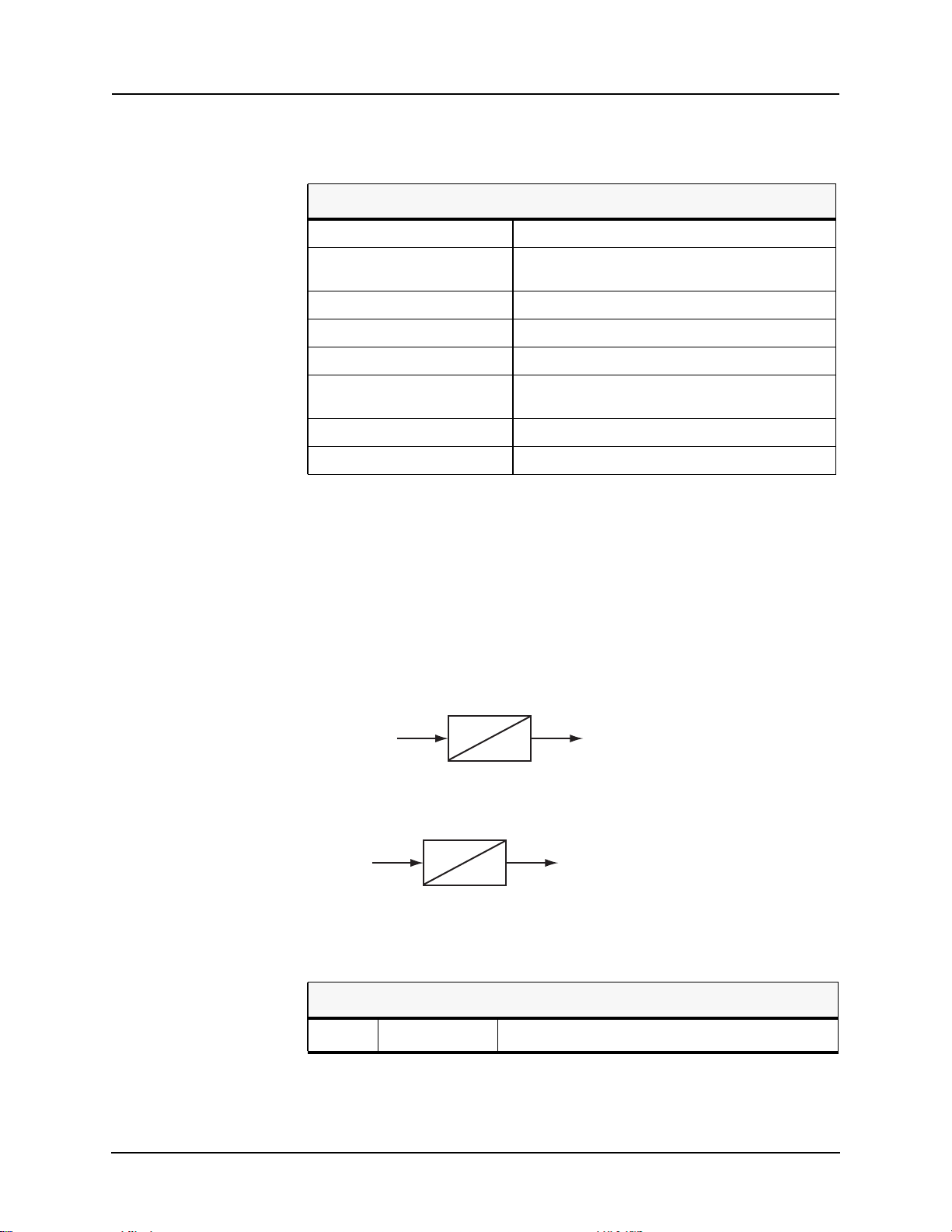
4 Protection Functions and Specifications
Figure 4.18: 60 CT Supervision
Table 4.17: 60 CT Supervision Settings
Main Enable/Disable
Inps Pickup 0.25 to 5.00 A secondary (5A)
Vnps Pickup 7.00 to 110.00 V secondary
Pickup Delay 0.03 to 99.99 seconds
Auxiliary Enable/Disable
Inps Pickup 0.25 to 5.00 A secondary (5A)
Vnps Pickup 7.00 to 110.00 V secondary
Pickup Delay 0.03 to 99.99 seconds
0.05 to 1.00 A secondary (1A)
0.05 to 1.00 A secondary (1A)
81 Frequency The relay has 4 frequency devices available. Each frequency element can be
set to operate either at a fixed level of under-frequency, a fixed level of overfrequency, or at a rate of change level (df/dt). The df/dt function can be set to
operate for a positive rate of change or a negative rate of change. Each frequency element has a definite time delay setting to create a time delayed output. A
fixed level of positive sequence voltage of 0.25 pu provides an undervoltage
inhibit on each element
Frequency (Hz)
Figure 4.19: Frequency Fixed Level
df/dt (Hz/s)
Figure 4.20: Frequency Rate of Change
Table 4.18: 81 Over/Under Frequency Settings
T
O
T
O
Disabled/Fixed Level/Rate of Change
4-34 L-PRO 4000 User Manual D02706R02.30
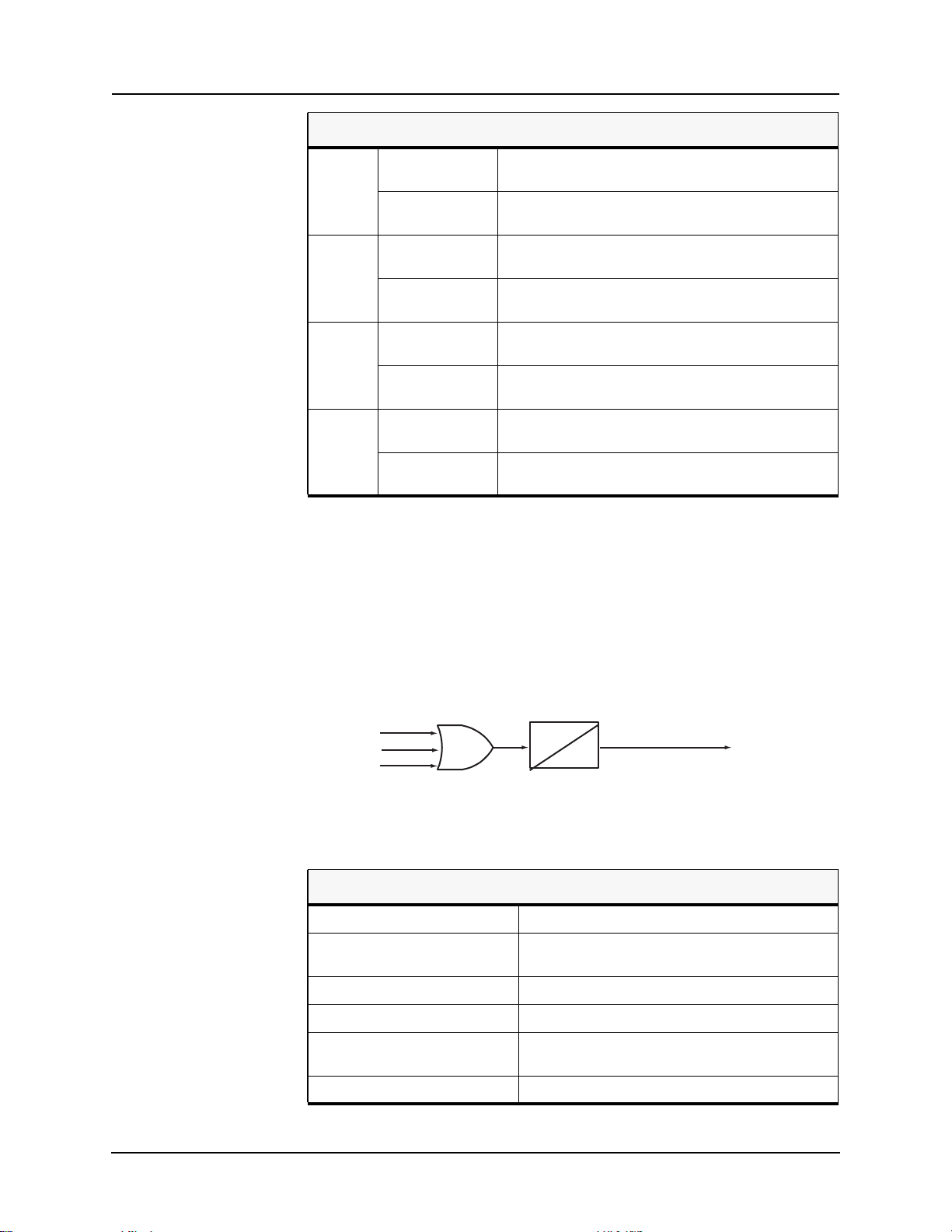
4 Protection Functions and Specifications
Table 4.18: 81 Over/Under Frequency Settings
Pickup
81.1
Pickup Delay
Pickup
81.2
Pickup Delay
Pickup
81.3
Pickup Delay
Pickup
81.4
Pickup Delay
50.000 to 59.995 or 60.005 to 70.000 (fixed level)
-10.0 to -0.1 or 0.1 to 10.0 (rate of change)
0.05 to 99.99 seconds (fixed level)
0.20 to 99.99 seconds (rate of change)
50.000 to 59.995 or 60.005 to 70.000 (fixed level)
-10.0 to -0.1 or 0.1 to 10.0 (rate of change)
0.05 to 99.99 seconds (fixed level)
0.20 to 99.99 seconds (rate of change)
50.000 to 59.995 or 60.005 to 70.000 (fixed level)
-10.0 to -0.1 or 0.1 to 10.0 (rate of change)
0.05 to 99.99 seconds (fixed level)
0.20 to 99.99 seconds (rate of change)
50.000 to 59.995 or 60.005 to 70.000 (fixed level)
-10.0 to -0.1 or 0.1 to 10.0 (rate of change)
0.05 to 99.99 seconds (fixed level)
0.20 to 99.99 seconds (rate of change)
Four frequency elements are provided with adjustable definite time delays.
Frequency is determined from the main voltage input (3 phase voltage).
50LS Overcurrent
The relay takes in currents from main, auxiliary CTs and 2 additional CT inputs, 50LS Input 3 and 50LS Input 4. These individual overcurrent devices can
be used with ProLogic to create logic. 50LS Input 3 and 50LS Input 4 are not
available in the Output Matrix.
50 I1a RMS
50 I1b RMS
50 I1c RMS
Figure 4.21: Low Set Overcurrent
Table 4.19: 50LS Low Set Overcurrent Settings
Main (Input 1) Enable/Disable
Pickup 0.10 to 50.0 A secondary (5A)
Pickup Delay 0.00 to 10.00 Seconds
Auxiliary (Input 2) Enable/Disable
Pickup 0.10 to 50.0 A secondary (5A)
T
0.02 to 10.0 A secondary (1A)
0.02 to 10.0 A secondary (1A)
Low Set Overcurrent
0
Pickup Delay 0.00 to 10.00 Seconds
D02706R02.30 L-PRO 4000 User Manual 4-35

4 Protection Functions and Specifications
Table 4.19: 50LS Low Set Overcurrent Settings
Input 3 Enable/Disable
Pickup 0.10 to 50.0 A secondary (5A)
Pickup Delay 0.00 to 10.00 Seconds
Input 4 Enable/Disable
Pickup 0.10 to 50.0 A secondary (5A)
Pickup Delay 0.00 to 10.00 Seconds
0.02 to 10.0 A secondary (1A)
0.02 to 10.0 A secondary (1A)
50BF Breaker Failure
The Breaker Failure (BF) protection function detects breaker failures. There
are 2 sets of breaker failure protection functions, 50BF Main and 50BF Auxiliary, one for each breaker. When breaker failure is initiated by a trip or other
internal logic (user-settable through the output matrix) and the breaker current
still exists, 2 timers (T1 and T2, user-settable) are started. When these timers
are timed out and if the current still exists (which indicates breaker failure), the
output of this function is set high. Use the 2 outputs of this function to trip another trip coil or the next level of breakers, such as bus breakers.
Figure 4.22: 50BF Main Breaker Failure
Table 4.20: 50BF Breaker Failure Settings
Main Enable/Disable
Pickup Delay 1 0.01 to 99.99 Seconds
Pickup Delay 2 0.01 to 99.99 Seconds
Breaker Current Pickup 0.10 to 50.0 A secondary (5A)
0.02 to 10.0 A secondary (1A)
4-36 L-PRO 4000 User Manual D02706R02.30

4 Protection Functions and Specifications
Table 4.20: 50BF Breaker Failure Settings
Auxiliary Enable/Disable
Pickup Delay 1 0.01 to 99.99 Seconds
Pickup Delay 2 0.01 to 99.99 Seconds
Breaker Current Pickup 0.10 to 50.0 A secondary (5A)
0.02 to 10.0 A secondary (1A)
Auxiliary (Input 2) Enable/Disable
External Single Phase 50BF Initiate
Main
A Phase Disabled, EI 1 to EI 20, PL1 to PL24
B Phase Disabled, EI 1 to EI 20, PL1 to PL24
C Phase Disabled, EI 1 to EI 20, PL1 to PL24
Auxiliary
A Phase Disabled, EI 1 to EI 20, PL1 to PL24
B Phase Disabled, EI 1 to EI 20, PL1 to PL24
C Phase Disabled, EI 1 to EI 20, PL1 to PL24
The L-PRO breaker failure protection can be initiated by any protection function located within the L-PRO relay by initiating the BFI column in the Output
Matrix screen. When the breaker failure function is initiated this way several
modes of operation may occur.
1. If the 3 Pole tripping option for the relay is selected, initiation of the BFI
column in the Output matrix will result in 3 pole breaker failure initiation.
Output of the breaker failure function will then be a three pole output. The
3 pole BF initiation will occur regardless of the type of fault detected, single phase or multi-phase fault.
2. If the 1 Pole (single pole) tripping option for the relay is selected, initiation
of the BFI column in the Output matrix will result in a 1 pole breaker failure initiation if a single phase trip by a protection function operates. If a
multi phase fault occurs, a multi-phase protection function will be initiated
and the BF initiation will be a 3 pole breaker failure. For this case all three
poles of the breaker will be checked to see if they open correctly. Breaker
failure operation will result in 3 pole backup breaker tripping just like the
single pole BF initiation.
3. If the 1/3 Pole Scheme tripping option for the relay is selected, the breaker
failure initiation will be a combination of (1) and (2) above, with single or
three pole BF initiation as required by the fault detection.
The breaker failure function can also be initiated by an input to one of the external inputs from an outside protective relay or by a ProLogic input. This input
can be a phase segregated input that can come from a single pole trip from an
external relay and is shown on the Scheme Selector screen.
D02706R02.30 L-PRO 4000 User Manual 4-37

4 Protection Functions and Specifications
The breaker failure logic uses a current detector that is user settable in the 50BF
Setting screen to determine whether a pole is open or closed in the range of 0.1
- 50 A secondary. There are two (2) breaker failure functions available per line
breaker with adjustable pickup definite time delays from 0.01 to 99.9 seconds.
In any case, the output of the Breaker Failure function must be set to close output contacts to perform its function. This is done by mapping the BF output to
the appropriate output contact in the Output Matrix screen.
50/51/67 Phase Overcurrent
Phase Overcurrent provides backup protection to the line. The user can define
directional or non directional control on either 50 or 51 functions.
Device 51 provides 3 IEC inverse time curve types, 3 IEEE inverse time types
of overcurrent protection and one user-defined curve. The equation and the parameters of Device 50/51/67 are listed below.
Table 4.21: IEC and IEEE Curves
No Curve Type A B p TR
1 IEC Standard Inverse 0.14 0.00 0.02 13.5
2 IEC Very Inverse 13.50 0.00 1.00 47.3
3 IEC Extremely Inverse 80.00 0.00 2.00 80
4 IEEE Moderately Inverse 0.0103 0.0228 0.02 0.97
5 IEEE Very Inverse 3.922 0.0982 2.00 4.32
6 IEEE Extremely Inverse 5.64 0.0243 2.00 5.82
7 User-defined [0.001, 1000] [0.0, 10.0] [0.01, 10.0] 0.1, 100
The equation of Devices 50/51/67 is given in Equation (3 and 4) below. The
various parameters are defined in Table 4.22: 50/51/67 Phase Overcurrent Settings on page 39.
For I > pickup
A
I TMS B
For I < pickup
TI TMS
4-38 L-PRO 4000 User Manual D02706R02.30
------------------------------------+=
------------------
Pickup
TR
-----------------------------------=
I
------------------
Pickup
p
I
2
1–
1–
(5)
(6)

4 Protection Functions and Specifications
Table 4.22: 50/51/67 Phase Overcurrent Settings
50 Enable/Disable
Directional Directional, non-directional or combined
Pickup 0.50 to 150.00 A secondary (5A)
0.10 to 30.00 A secondary (1A)
Pickup Delay 0.00 to 99.99 seconds non-directional
0.01 to 99.99 seconds directional
51 Enable/Disable
Directional Directional, non-directional or combined
Pickup 0.25 to 25.00 A secondary (5 A)
0.05 to 5.00 A secondary (1 A)
Curve Type For details see Table 4.21: IEC and IEEE Curves on page
38.
TMS 0.01 to 10.00
A 0.0010 to 1000.0000
B 0.0000 to 10.0000
p 0.01 to 10.00
TR 0.10 to 100.00
Directional Angle Setting
Alpha -179.90 to 180.00
Beta 0.10 to 360.00
Phase Setting Multiplier for Single-Phase Open Pole Condition
50 Pickup Current Multiplier 0.10 to 2.00
50 Pickup Time Multiplier 0.10 to 2.00
51 Pickup Current Multiplier 0.10 to 2.00
51 Pickup Time Multiplier 0.10 to 2.00
D02706R02.30 L-PRO 4000 User Manual 4-39

4 Protection Functions and Specifications
50N/51N/67 Neutral Overcurrent
Neutral overcurrent provides backup protection for line to ground faults. The
user can define directional or non directional control on either 50N or 51N
functions. 51N can also be configured for use in the communication scheme.
All the curve definitions are the same as the phase overcurrent except that this
function uses 3I0 rather than phase current. The equation is:
For 3I0 > pickup
For 3I0 < pickup
3I 0TMS B
T 3 I 0TMS
A
------------------------------------+=
------------------
Pickup
TR
-----------------------------------=
3IO
------------------
Pickup
3I 0
p
2
1–
1–
(7)
(8)
All parameters for Equations 5 and 6 are defined in Table 4.23: 50N/51N/67
Neutral Overcurrent Settings on page 40.
Table 4.23: 50N/51N/67 Neutral Overcurrent Settings
50N Enable/Disable
Directional Directional, non-directional, combined
Pickup (3I0) 0.25 to 50.00 (5 A)
0.05 to 10.00 (1 A)
Pickup Delay 0.00 to 99.99 seconds non-directional
0.01 to 99.99 seconds directional
51N Enable/Disable
Directional Directional, non-directional, combined or direction in scheme
Pickup (3I0) 0.25 to 50.00 (5 A)
0.05 to 10.00 (1 A)
Curve Type For details see Table 4.21: IEC and IEEE Curves on page 38.
TMS 0.01 to 10.00
A 0.0010 to 1000.0000
B 0.0000 to 10.0000
p 0.01 to 10.00
TR 0.10 to 100.00
Directional Angle Setting
Alpha -179.90 to 180.00
Beta 0.10 to 360.00
4-40 L-PRO 4000 User Manual D02706R02.30

4 Protection Functions and Specifications
Table 4.23: 50N/51N/67 Neutral Overcurrent Settings
Phase Setting Multiplier for Single Phase Open Pole Condition
50N Pickup Current Multiplier 0.10 to 2.00
50N Pickup Time Multiplier 0.10 to 2.00
51N Pickup Current Multiplier 0.10 to 2.00
51N Pickup Time Multiplier 0.10 to 2.00
46-50/46-51/67 Negative Sequence Overcurrent
Negative Sequence Overcurrent provides further backup protection for any unbalanced faults. The user can define directional or non directionall control on
either 46-50 or 46-51 functions. All the curve definitions are the same as the
Phase Overcurrent. The only difference is that this function uses the negative
sequence current (I2) rather than phase current. The equation is:
For I2 > pickup
A
TI2 TMS B
For I2 > pickup
TI2 TMS
Table 4.24: 46-50/46-51N/67Negative Sequence Overcurrent Settings
46-50 Enable/Disable
------------------------------------+=
------------------
Pickup
TR
-----------------------------------=
I 2
------------------
Pickup
I 2
p
2
1–
1–
(9)
(10)
Directional Directional, non-directional or combined
Pickup 0.50 to 50.00 (5 A)
0.10 to 10.00 (1 A)
Pickup Delay 0.00 to 99.99 seconds non-directional
0.01 to 99.99 seconds directional
46-51 Enable/Disable
Directional Directional, non-directional or combined
Pickup 0.50 to 50.00 (5 A)
0.10 to 10.00 (1 A)
Curve Type For details see Table 4.21: IEC and IEEE Curves on page
38.
TMS 0.01 to 10.00
D02706R02.30 L-PRO 4000 User Manual 4-41

4 Protection Functions and Specifications
Table 4.24: 46-50/46-51N/67Negative Sequence Overcurrent Settings
A 0.0010 to 1000.0000
B 0.0000 to 10.0000
p 0.01 to 10.00
TR 0.10 to 100.00
Directional Angle Setting
Alpha -179.90 to 180.00
Beta 0.10 to 360.00
Phase Setting Multiplier for Single Phase Open Pole Condition
46-50 Pickup Current Multiplier 0.10 to 2.00
46-50 Pickup Time Multiplier 0.10 to 2.00
46-51 Pickup Current Multiplier 0.10 to 2.00
46-51 Pickup Time Multiplier 0.10 to 2.00
Adaptive Additional Delay for 50 O/C Elements
The relay provides an adaptive additional time delay (maximum 16 ms) response to the 50 O/C elements to prevent operation during RFI testing with
minimal pickup set points and operation near pickup.
This adaptive delay is applied to: 50LS-1, 50LS-2, 50LS-3, 50LS-4, 50, 50N,
46/50.
If the Pickup Delay setting (Tp) < 20ms AND Pickup Level setting <I
nominal
(nominal current), an extra 8 ms delay is added. After this 8 ms timer expires,
if I < threshold, the second 8ms extra delay will be added in addition to the
original Tp. If I > threshold after the first 8ms timer expires, only Tp is used
for the delay. (Note Tp is the setting which is less than 20ms, could be 0ms).
The threshold is equal to 2*PickupLevel if pickup is between 40%*I
I
40%*I
inal
(i.e. between 2 A and 5 A for 5 ACT). The threshold is equal to
nominal
if 2*PickupLevel < 40%*I
nominal
if 2*PickupLevel>I
nominal
. The threshold is equal to I
nominal
nominal
and
nom-
4-42 L-PRO 4000 User Manual D02706R02.30

Z Circle Trigger
4 Protection Functions and Specifications
X
Z
R
Figure 4.23: Z Circle Trigger
Table 4.25: Z Circle Trigger Settings
Z Circle Trigger Enable/Disable
Positive Sequence Impedance 0.1 to 50.0 ohms secondary (5 A)
0.5 to 250.0 ohms secondary (1 A)
The Impedance Circle Trigger (Z Circle Trigger) triggers the relay to record on
a dynamic swing disturbance — only used to trigger a recording. This trigger
is usually set outside the last protection zone used and blocked during LOP
conditions.
Fault Locator Whenever a fault occurs and the line trips, the fault locator calculates the fault
type and the distance to the fault. This information is available from the front
display of the relay or through Port 150, 123 or the SCADA port or through
Relay Control Panel software. Fault locator information can also be captured
optionally in event records. Fault locator can be enabled/disabled through settings (system parameters).
The fault locator is initiated by the following logic:
• 21 Trip
• 50N Trip
• 51N Trip
• Scheme Trip
• 21 Alarm (configurable)
The relay fault locator uses the Takagi method of fault location. The impedance calculated for a fault initiated by any of the above functions will be calculated and compared with the line impedance to calculate distance to fault.
D02706R02.30 L-PRO 4000 User Manual 4-43

4 Protection Functions and Specifications
Mutual Compensation
The fault locator has the ability to take into account mutual compensation for
up to two lines in parallel with the protected line where the relay is applied.
The currents from the parallel line (s) is brought into the relay via spare current
inputs I
determine the parallel line 3
parallel line 3
and IA4. The currents from up to two parallel lines can be added to
A3
I0
currents.
I0
1. Connect all 3 phases of the first parallel line into the I
are recorded by the relay if a recording initiation occurs and are added by
the relay to obtain 3 I
to be used in the line impedance to fault calcula-
01
tion. Alternatively, the neutral current from line 1 CTs can be connected to
. This quantity is added with the other line 1 phase current inputs (which
I
A3
= IC3 = 0 since no connection is made) to obtain line 1 residual 3I0
are I
B3
current. If this is done, the individual line 1 phase currents is not recorded
by the relay.
2. Connect the currents from the second parallel line (if present) in a similar
way to that of line 1.
ProLogic ProLogic Control Statements
Using ProLogic, the relay can pick any of the protection functions, external inputs or virtual inputs and place them into Boolean-like statements. ProLogic
handles up to 5 functions to generate one ProLogic statement; 24 statements
are possible. The results from these statements are mapped to output contacts
using the output matrix.
current. There are two possible ways to get the
inputs. The currents
A3
The ProLogic control statements are used to create Boolean-like logic. The relay can use any of the protection functions or external inputs combined with
logic gates to create a ProLogic control statement. The possible gates are AND,
NAND, OR, NOR, XOR, NXOR, and LATCH. The control can be time delay
pickup and or time delay dropout, and can drive the front panel target LED.
Twenty-four ProLogic control statements outputs are available and can be used
in the output matrix to customize the relay to specific needs. Inputs to ProLogic
are all the elements plus previous ProLogic statements for logic nesting usage.
The example, for details see Figure 4.24: ProLogic on page 4-44, shows A to
E inputs are status points of devices that are user-selectable. Each ProLogic
output can be given a specific name, pickup and reset time delay.
Op 1
A
B
C
D
E
Figure 4.24: ProLogic
Op 2
Op 3
Op 4
Op 5
T
O
4-44 L-PRO 4000 User Manual D02706R02.30

Table 4.26: ProLogic Setting Functions
Name Give the ProLogic a meaningful name
Pickup Delay Delay time from pickup to operate
Dropout Delay Delay time from dropout to a ProLogic status
A, B, C, D, E Relay elements as input statements
Operators Boolean-type logic gates
Group Logic Group Logic Control Statements
The relay has 8 Setting Groups (SG). The user can change all relay setting parameters except the physical connections such as input or output parameters in
each setting group. Setting group changes are performed by using any one of
the 16 available Group Logic statements per setting group. The Group Logic
statements are similar to the ProLogic statements with the following exceptions – the sole function is to activate one of the 8 setting groups and the processing is in a slower half second cycle. Group Logic inputs statements are
driven from ProLogic or any external input or virtual input or from previous
Group Logic statements. Each Group Logic statement includes 5 inputs (with
Boolean statements), one latch state and one pickup delay timer. The Active
Setting Group (ASG) is viewed from the Terminal Mode, the front panel or
from a record stored by the relay, the ASG is stored with the record).
4 Protection Functions and Specifications
of low
Group Logic Processing
The 16 Group Logic statements reside in a slower processing thread within the
relay protection algorithms. The processing cycle happens once every half second (0.5 second). When using ProLogic statements remember that a latch or
dropout timer should be used if the initiating condition does not last at least 0.5
seconds. In the example following, we will create a definite pulse length using
ProLogic, for details see “L-PRO Setting Example” in Appendix L.
Default Setting Group
The relay uses Setting Group 1 as the factory default setting group and retains
the current active setting group in memory. This allows the relay to use the last
active setting group prior to interruption of relay power as the default setting
group following power up.
Change Active Group
The user can at any time change the active setting group. When initiating a setting group change, this change takes precedence over an automatic setting
group change.
D02706R02.30 L-PRO 4000 User Manual 4-45

4 Protection Functions and Specifications
The setting group can be changed using the Relay Control Panel, with either
Change or Service access level, using the following path:
In this tab, choose desired setting group number and hit Save.
The setting group can also be changed using the relay display interface, after
login in with the Change or Service access level, using the following path:
In this screen, highlight the group number, and then hit Edit. Choose the desired setting group number, and then hit Enter with the cursor in the return
character (bottom right).
Relay Control Panel > Utilities > Settings Group
Main Menu > Utilities > Maintenance > Settings Group Control
Figure 4.25: Settings Group Control
Figure 4.26: Settings Group Control change
The protection processor does not have any interruption in service.
Automatic Settings Change
Relay configuration changes during a relay-initiated setting; change does not
disrupt the relay protection functions. Since the relay setting file does not
4-46 L-PRO 4000 User Manual D02706R02.30

change, the interface processor uses the new setting group ancillary setting information at the same time as the protection processor switches to the new setting group. An event is logged to show when the new setting group is in
service.
4.1 Communication-Aided Scheme
The relay provides 4 communication aided tripping scheme options. Permissive Over-Reaching Transfer Trip (POTT), a combination of POTT with Weak
Infeed (WI), Directional Comparison Blocking (DCB) or Permissive UnderReaching Transfer trip (PUTT) are available to be used with external telecommunications devices for enhanced tripping of the protected line. The combination of phase distance, ground distance and neutral overcurrent elements
provide flexible setting options for the selected communication aided tripping
scheme.
Logic for 2 communication receivers can be used for 3 terminal lines or if the
telecommunications use 2 separate communication channels. The user can set
the communications receivers to use one of 20 external inputs or one of the 24
ProLogic statements. The same input cannot be shared between the 2 communication receivers.
4 Protection Functions and Specifications
50/51N OC Carrier Start and Block Logic
The output matrix is used to configure the communications scheme send (permissive trip or block), and the communications scheme trip (local tripping) to
any combination of the 21 available output contacts. The user-set dropout extension on output contacts is eliminated on any contact that is configured to operate for the communication scheme send signal; The user can provide the
dropout time delay with timer setting TD3.
The communications aided tripping scheme options use the general distance
and overcurrent protection functions of the relay, along with directional overcurrent elements specifically included in the scheme. These elements use the
memory polarization as described in the “Relay Method of Memory Polarization” on page 4-8 and the directional element as described in “Directional Element” on page 4-10.
The carrier start logic is traditionally initiated by the Zone 2 distance elements,
but the relay provides 2 directional neutral overcurrent elements that can be
used in addition to the Zone 2 distance elements. The device 51N time overcurrent element, and the 50N/67F instantaneous overcurrent if enabled can be
configured to drive the carrier start logic. The 51N is configured in the 50N/
51N screen, while the 50N/67F is configured in the scheme selector screen,
both elements are forward directional elements.
The carrier block logic is traditionally initiated by the Zone 4 distance elements, but the relay provides one directional neutral overcurrent element that
can be used in addition to the Zone 4 distance elements. The device 50N/67R,
if enabled, can be configured to drive the carrier block logic. The 50N/67R is
configured in the scheme selector screen and is a reverse directional element.
The scheme selector can also be configured to enable the 50N/67F and 50N/
67R directional overcurrent elements as inputs to ProLogic statements. The
D02706R02.30 L-PRO 4000 User Manual 4-47

4 Protection Functions and Specifications
50N/67F element can be set to either forward directional or non-directional
when selecting the action, “ProLogic Only”.
If the pickup delay setting (Tp) < 9 ms, then 9 ms will be used for the delay.
Otherwise Tp will be used for the delay. This change is always applied regardless of the direction setting (Non-dir, FWD, REV) and the 3
pickup level.
I0
Note: If the directional element cannot determine a valid direction, the direction is set to “forward”, the 50N/67F may operate, and the 50N/67R element is
blocked. See “Directional Element” on page 4-10.
Basic Logic The basic selection does not provide any communication-aided logic for local
or remote protections.
101
PUTT SCHEME
(If DCB shceme is
selected, Zone 4 must
be set reverse)
DCB SCHEME
WEAK INFEED LOGIC
50N-67R
20ms
Rece iver #1
Receiver #2
60
0
102
(+)
21-2
105
21-4 R
104
6ms
108
TWD1
110
3ms
TWD2
27 V1
113
59 V0
Rece iver #1
Rece iver #2
103
106
0
111
TWD3
112
0
TD2
TL2
0
Weak Infeed Enable
Swit ch
107
POTT SCHEME
Forward
Non-direct ional
3I0 > Pickup
Rever s e
Receiver #1
Receiver #2
51N Alarm
50N-67F
21P 2
3I0 > Pickup
(+)
21N 2
121
122
120
(+)
TL1
116
TD1
21N 1
21P 2
21N 2
21P 4
21-2
21N 4
114
TCS
0
TCB
0
21P 1
117
118
115
119
POTT
DCB
BASIC
SCHEME SELECTOR
Trip
PUTT
POTT
DCB
PUTT
BASIC
TL3
TD3
TL3, TD3 range: 0-1s
Send
Figure 4.27: Communication-aided Scheme
4-48 L-PRO 4000 User Manual D02706R02.30

4 Protection Functions and Specifications
POTT Logic The POTT logic is used for tripping schemes where the local end over-reaches
the remote end for forward fault conditions, for details see Figure 4.27: Communication-aided Scheme on page 4-48. The local end sends a permissive trip
signal to the remote end when one of the forward directional elements operates.
The scheme send signal (permissive transfer trip send) is time delayed by timer
setting TL3; the local end is required to sense a forward fault for durations
greater than TL3. The local end does not produce a scheme trip output unless
the remote has detected a forward directional fault and sends the similar permissive trip signal to the local end. The local end senses a permissive trip receive signal and the scheme trip closes the output contacts and removes the
fault contribution from the local end. The remote end acts in a similar fashion
and the fault contribution is removed from the remote end.
Current reversal logic guards against incorrect permissive tripping for installations with parallel lines where one end of the un-faulted line is contributing
fault current and the other end of the un-faulted line is over-reaching and sending a permissive trip signal. The local reverse directional elements are used
with the permissive receive signal from the remote end to form the blocking
logic. The blocking logic is time delayed by timer setting TL1; the local end is
required to sense reverse faults while receiving the remote permissive trip for
durations greater than TL1. The blocking logic continues to block the scheme
send and scheme trip signals when the reverse fault detection or permissive trip
receive signals go low. Timer setting TD1 determines the current reversal
block extension time.
For line terminals with a weak source, fault conditions could occur on the protected line where no elements operate at the weak source. Weak infeed (WI)
logic enables the relay to protect lines where one end of the line has no source
or has a very weak source. The WI scheme can only be enabled if the user has
selected the POTT scheme otherwise it is disabled. If enabled, the WI feature
enhances the POTT tripping logic.
WI enables the POTT scheme to quickly isolate line faults where one end of
the line has a high source of impedance.
During fault conditions where no weak source elements pick up the WI logic
echoes back the permissive transfer trip signal received by the weak source. If
a permissive transfer trip is received from the remote line end, AND 110, AND
111 and OR 115 echo a POTT signal back to the remote end. The permissive
transfer trip signal is required to last for durations greater than 20 ms. A 3 ms
time delay pickup and time delay dropout timer TWD2 determine the amount
of time between permissive transfer trip receive signals that the scheme echoes
back. If the permissive transfer trip receive signal is constantly high the WI
logic only echoes back for a time equal to TWD3 plus 3ms. If the PT signal
being received resets then starts up again, after timer setting TWD2, a new permissive transfer trip signal echoes back.
The WI logic blocks when forward or reverse faults are detected, the logic is
also blocked for a loss of potential condition. During a reverse or a forward
fault condition, the Zone 2, Zone 4, 51N, or 50N/67 elements could pick up. If
any of these functions pick up, they block the WI scheme by putting a high input into inverted input of AND 110. The blocking condition is required last for
D02706R02.30 L-PRO 4000 User Manual 4-49

durations greater than 6 ms. The blocking logic continues to block the scheme
send and scheme trip signals when the fault detection or loss of potential signals go low. Timer setting TWD1 determines the block extension time. TWD1
should be set to coordinate with the communication-reset time of the PT signal.
It should be set greater than the time it takes for the remote end’s Zone 2 to reset and for the PT channel to reset.
Timer setting TWD2 should be set to a time that prevents chattering of the
communications channel. If TWD2 is allowed to reset before the remote end
(strong source) clears the fault and stops sending the permissive transfer trip
signal the WI echoes back another block of permissive transfer trip send.
The WI logic is also used to provide local tripping if both ends of the line are
to be isolated. The line voltages provide supervision with a positive sequence
under-voltage element (27V1) and a zero sequence over-voltage element
(59V0). If a permissive transfer trip is received from the remote line end, AND
110, AND 112, OR 113 and OR 119 provide a local tripping signal.
DCB Logic The DCB logic is used for tripping schemes where the local end over-reaches
the remote end for forward fault conditions, for details see Figure 4.27: Communication-aided Scheme on page 4-48. Typically DCB is used when the communications link may be disrupted during fault conditions, for example power
line carrier. The local end sends a block trip signal to the remote end when one
of the enabled reverse directional elements operates. The scheme send signal
(block trip send) is time delayed by timer setting TL3, the local end is required
to sense a reverse fault for durations greater than TL3. If one of the forward
directional elements operates the blocking logic does not operate. For forward
directional fault conditions the DCB logic is time delayed by timer setting TL2.
The forward fault condition has to last for durations greater than TL2. The local
end does not produce a scheme trip output if the remote has detected a reverse
directional fault and sends the similar block trip signal to the local end. The local end senses a block trip receive signal and the scheme trip logic is disabled
with no intentional delay. Current reversal logic guards against incorrect local
tripping for installations with parallel lines where one end of the un-faulted line
is contributing fault current and the other end of the un-faulted line is reversereaching and sending a block trip signal. The local forward directional elements are supervised by the block receive signal from the remote end to form
the blocking logic. The blocking logic reset is time delayed by timer setting
TD2; the local end is required to receive the remote block trip for durations
greater than 0 ms. The blocking logic continues to block the scheme trip signals
when the block trip receive signal goes low. Typically the block reset timer
TD2 is set longer than the forward directional elements reset time.
 Loading...