

ERKO SH400PLC Operation Manual
ISO 9001 ISO 14001
OPERATION MANUAL
BUSBAR PROCESSING SITE
SH400PLC TYPE
SWW 0792 #VSH400PLC090909 PKWiU 29.56.25-90.00
Producent / Producer / Производитель
Zakłady Metalowe ERKO R. Pętlak spółka jawna
ul. Ks. Jana Hanowskiego 7, 11-042 JONKOWO k/OLSZTYNA
tel./fax (+48) 089 5129273 NIP: 739-020-46-93
e-mail: sprzedaz@erko.pl, export@erko.pl serwis informacyjny: www.erko.pl.
Bracia Pętlak

- 1 -
Before using this equipment, please carefully read the user and the maintenance
Thank you for buying our product.
manuals.
* ERKO has the right to introduce construction modifications due to equipment
modernization.
# VSH400PLC090909

- 2 -
TABLE OF CONTENTS
1 APPLICATION…………………………………………………………… 3
2 TECHNICAL DATA.....………………………………………………….. 3
3 ACCESSORIES…………………………………………………………. 4
4 MACHINE INSTALLATION…………………………………………….. 5
5 CONTROL PANEL……………………………………………………… 5
6 SOFTWARE……………………………………………………………… 6
7 ZERO ADJUTING OF THE MEASUREMENT SYSTEM…………… 11
8 TECHNOLOGY………………………………………………………….. 17
9 MAINTENANCE AND OPERATION RECOMMENDATIONS……… 23
10 HYDRAULIC GENERATOR……………………………………………. 24
11 WORK SEFETY AND HYGIENE MANUAL………………………….. 27
12 SERVICING……………………………………………………………… 27
13 DISPOSAL……………………………………………………………….. 27
# VSH400PLC090909

- 3 -
Before using this equipment, please read the user and the
safety manuals.
The equipment can be used only with Al and Cu rails
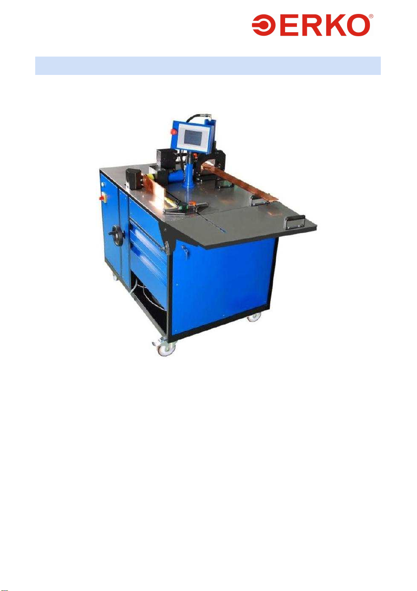
1. APPLICATION
The SH 400PLC machine can be used for cutting, die blanking and bending copper
and aluminum rails with electronic measurement of the angle and the distance
between the hole and the front of the rail, equipped with a touch display.
The basic features which ensure the efficient and precise operation of the equipment
include:
Programmable sensor of the bending angle (accuracy 0.1°)
Built-in measurement bar for positioning within an accuracy of 0.1 mm.
Precise regulation of the height of the hole cutting head (accuracy 0.1 mm).
Making round and oval holes without burrs
Rail cutting without distortion or burr
Pedal control
Built-in reliable hydraulic drive
2. TECHNICAL DATA
Station weight
Max dimensions L x W x H
Max table dimensions
Working pressure
Working pressure on the head outlet
Power supply 3x400/230 V 50 Hz, 1.4kW
Control
Supply plug
Protection degree
Busway machining (Cu, Al) (thickness X width)
Bending range
782.64lb
1400 x 850 x 1420 mm
2030 x 715
630 bar
630 bar
24V DC
16A 400V 3P N+E IP44
(PCE 015-6v)
IP40
12 x 125 mm
0÷90°
# VSH400PLC090909
- 4 -
3. ACCESSORIES
The station is equipped with the following accessories:
1. Complete table (1 item)
2. Control system (1 item)
3. Hydraulic power system (1 item)
A high pressure 630 bar hydraulic conduit with a PM connection for feeding
4.
external heads. (1 item)
5. The body of the cutting and hole cutting segment. (1 item)
6. Software (1 item)
7. Technical documentation (1 item)
Standard versions of the SH400PLC station
Accessories
A precision bending insert (built-in encoder)
Rail cutter
Cut rail length gauge
Rail offsetting insert
Additional side tabletop
Extended length measurement (range from 0 to 1020)
Round hole cutter (dimensions as per the catalogue)
Oval hole blanking die (dimensions as per the
catalogue)
Rectangular hole blanking die (dimensions chosen by
the customer)
Insert for forcing in nuts
Additional rbusbar support
+ standard accessories
o additional accessories ordered individually by a customer
Code
SH 401PLC-E + + +
SH 405 + + +
SH 415PLC o o +
SH 406PLC o + +
SH 408PLC o o +
SH 418PLC o o +
SH 403 o o o
SH 404 o o o
SH 409 o o o
SH 407 o o o
SH 408 o o o
Additional equipment (optional):
SH_400PLC1-3F
SH400PLC-GOLD
SH_400PLC2-3F
SH400PLC-SILVER
SH_400PLC3-3F
SH400PLC-PLATINUM
External equipment as per ERKO catalogue:
GU 120
GU 300
GO 300 Head for clamping dies on cables 6 – 300 mm2, reforming sector
# VSH400PLC090909
Head for clamping dies on cables 10 – 120 mm2, reforming sector
conductors
Head for clamping dies on cables 10 – 300 mm2, reforming sector
conductors
- 5 -
conductors
GU 625 Head for clamping terminals on cables 300 – 625 mm2
GW Head for punching holes in switching cabinets
GC 50N Head for cutting cable conductors
GC 100 Head for cutting cable conductors
GL 6 Assembly rail cutter
GLP Assembly rail cutter
4. MACHINE INSTALLATION
The station should be positioned on hard and even foundation, so that it will
securely lean on all four wheels.
Operation of the station on an unadapted foundation may result in
accelerated wear and in some cases it can be a cause of a defect or
destruction of the station.
Block the brakes of the station wheels.
Connect the equipment to the electrical power supply.
In order to work properly, station type SH400PLC requires five-line electrical
network - L1, L2, L3, N, PE in any sequence of phases. For four-line network it is
necessary to bridge PE and N lines in the supply socket.
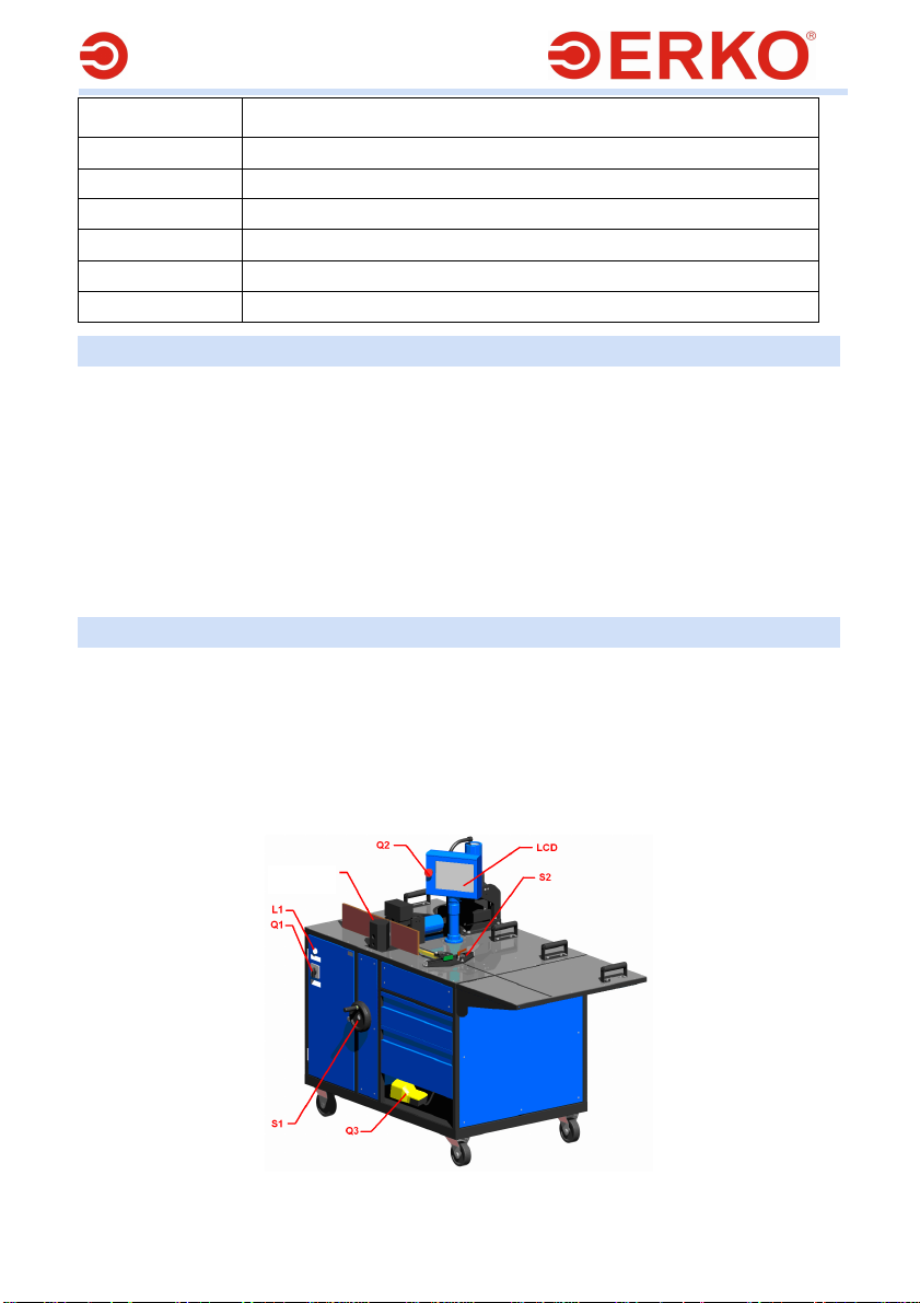
5. CONTROL PANEL
The control panel consists of the following elements:
The main switch Q1 – used for starting the station.
A white signalling lamp L1 – used for signalling correct power supply.
LCD panel with a touch screen – contains technological software.
Emergency stop switch Q2.
Foot switch Q3 – acts as an operational switch-key.
Body height regulating crank S1.
Limiter stop S2.
crank
Fig. 1.
# VSH400PLC090909
- 6 -
6. SOFTWARE
6.1 PREPARATION FOR WORK
NOTE:
In specific cases the software may deviate from that presented below.
Connecting and disconnecting the communication cord of the bending insert
(SH401PLC-E) is allowed only with the station power supply disconnected.
If it is necessary to remove the measuring insert frequently, place it in the immediate
storage area (Fig. 24) without disconnecting the communication cord.
In order to start the station, switch on the main switch Q1 to position I. Then a
screen (Fig. 2) will appear on the panel screen, where you will be asked to
choose the user interface language by clicking the appropriate flag.
After the appropriate language has been selected, the message “Communication
OK. on CAN” (Fig. 3) will appear, followed by the screen from which you will
select the type of operation (Fig. 4).
It is possible to change the menu language at any time by clicking the appropriate flag
on the bar at the top of the screen (Fig. 4)
If other messages or no messages appear, restart the station or, if this does not give
the desired result, contact the service.
# VSH400PLC090909
Fig. 2. Fig. 3
Fig. 4.
- 7 -
Work type selection:
Body: enables bending conductor rails, offsetting, die blanking and forcing in nuts.
Cutting: starts the SH 405 module for rail cutting.
Head: starts the external conduit for powering auxiliary devices with hydraulic oil.
After pressing the Body menu it is necessary to define the reference points on the
measurement bars. The programmer signals it with red areas H, L, A or H, L,
depending on the operation that is being performed.
In order to find them:
H-REF – turn the knob S1 upwards and/or downwards. As a result the red area should
disappear.
L-REF – Move the stop slide S2 from the body to the table end. As a result the red
area should disappear.
A-REF – Bend the angle measurement insert level, the insert must be connected with
the assembly socket. As a result the red area should disappear.
If only the HEAD (GŁOWICA) or CUTTING (CIĘCIE) menu is used, looking for
reference points is not necessary.
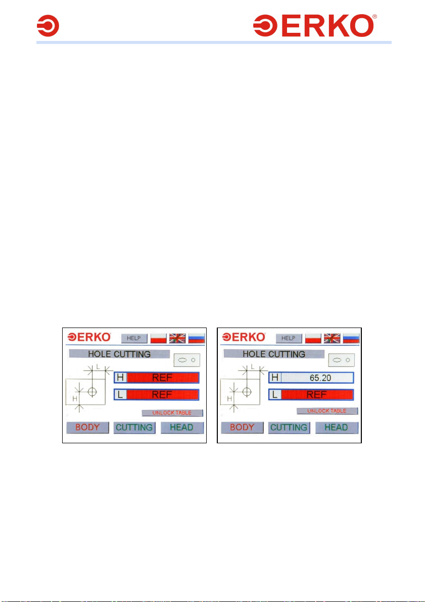
6.2 DIE BLANKING
Die blanking is the default option when you go to the BODY (KORPUS) menu is there
is no equipment in the body.
After starting the BODY (KORPUS) menu, a window will appear where you will have to
define the reference points of the measurement bars (Fig. 5.
After all these actions have been performed, the station is ready to work.
Fig. 5. Fig. 6
For the die blanking operation to be performed correctly, it is necessary:
To determine the distance between the hole centre and the lower rail
edge.
Turn the knob S1 so that the desired offsetting value will be displayed in
area H Fig. 6
To determine the distance between the hole centre and the right rail
edge.
# VSH400PLC090909
- 8 -
Move and block the stop slide S2 to the desired distance. The value of
offsetting is displayed in area L Fig. 7.
Fig. 7.
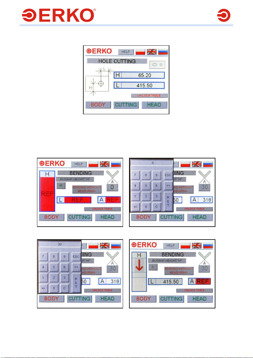
6.3 BENDING
In order to start the bending operation, go the BODY menu and equip the body with a
punch and the measuring insert SH 401PLC - E.After a mandrel is installed, a window
will appear where you will have to define the reference points of the measurement bars
(Fig. 8).
Fig.8 Fig.9
Fig.10 Fig.11
# VSH400PLC090909
 Loading...