

Page 1
SERVICE MANUAL
8T84 CHASSIS
Design and specifications are subject to change without prior notice.
( ONLY REFERRENCE)
ENGINEER BY: CHECKED BY: PPROVED BY:
_____
_____
_____
Page 2

Contents
Contents------------------------------------------------------------Technical specification-------------------------------------------Chassis Block Diagram-------------------------------------------Service Adjustments ----------------------------------------------Operation Instructions
---------------------------------------------
Circuit Diagram-----------------------------------------------------
2
3-8
9
10-11
12-26
27
-2-
Page 3
TECHNICAL SPECIFICATION
1.General Specification
Y Cb Cr/Y Pb Pr
5.
No
1. System 1) PAL BG/DK/I
2. Channel 1) VHF : K1~S7
3. Input Voltage
4. Market
5. Panel Size(inch) 15”/17’’/20’’
6. Tuning System FS
7. Operating Environment 1) Temp : 0 ~ 40 deg
8. Storage Environment 3) Temp : -20 ~ 50 deg
Item Specification Remark
2) SECAM BG/DK/L/L’
3) NTSC M *
CATV : S8~S38
UHF : S39~DS57
AC 110 ~ 240 V,50/60Hz
EUROPE, East ASIAN, Australian
2) Humidity : 40 ~ 85 %
4) Humidity : 30 ~ 90 %
2. Feature and Function
No
1. TELETEXT 10page
2. REMOCON RC5 Code
3. FULL SCART Input 1
4. Component input 1
VGA
6. 2 Carrier Stereo YES
7. NICAM Stereo Y
8. 2 Carrier Dual Y
9. NICAM Dual Y
10. SSC (Split Screen) Mode Option DUAL TXT PAGE
11. Headphone Y
12. 16:9 Mode Y
13. Noise Reduction Y
14. Progressive Scan(CTI) Option
15. Comb Filter Y
16. Tone control (Bass/ Treble/ Balance) Y
17. Customer LOGO Y
18. 5 Band Equalizer Y
Item Specification Remark
(480i/p, 720p, 1080i)
1
-3-
PDF 文件使用 "pdfFactory" 试用版本创建 www.fineprint.com.cn
Page 4
TECHNICAL SPECIFICATION
9.
No
19. Clock(Remind timer / Wake timer) Y
20. Child Lock Y
21. 4 Picture/Sound Mode Y
22. OSD Language English/French/Deutsch Others can be added
23. TXT Language East/west/pan
24. ATS Y
Item Specification Remark
European/Cyrillic/Greek
3. Safety and Regulation
No
1. Force Stability – Incline Plane Tip Test deg
2. Force Stability – Level Tip Test N
3. Isolation Gap, AC-AC/ AC-DC 3 mm
4. Isolation Gap, insulation- no insulation 6 mm
5. Power Consumption, Max 40 75 W 15’’/20’’ IEC 65
6. Power Consumption, Stand by 1 3 W
7. Power Consumption, Current harmonics IEC 107-1
8. Dielectric Voltage 3 kV at 10 mA, for 1 minutes
Isolation Resistance 4 MΩ
10. Leakage Current 0.7 mApp
11. Power Cord Captivity 15 kg
12. Flammability – Back Cover V0 UL94
13. Sharp Edge none
14. UL Compliance
15. FCC Compliance
16. CDRH Radiation Compliance
17. CSA Compliance
18. CEB Compliance
19. CE Compliance Y
20. CB Compliance Y
Item Min Typ Max Unit Remark
4. Video
No
1. Linearity Distortion, Vertical %
2. Linearity Distortion, Horizontal %
3. Trapezoidal Distortion, Vertical %
4. Trapezoidal Distortion, Horizontal %
5. Over Scan, Vertical %
6. Over Scan, Horizontal %
-4-
Item Min Typ Max Unit
PDF 文件使用 "pdfFactory" 试用版本创建 www.fineprint.com.cn
Remark
Page 5
TECHNICAL SPECIFICATION
No
7. Brightness, Maximum 100 cd/m
8. Video Noise Limited
Sensitivity(@S/N=30db) VHF
9. Video Noise Limited
Sensitivity(@S/N=30db)
UHF
10. Selectivity –1.5M 35 dB
11. Selectivity +8M 40 dB
12. Tuning Range -0.75 1 MHz
13. Resolution Horizontal 300 Lines
14. Resolution Vertical 400 Lines
15.
Item Min Typ Max Unit
2
48 dBm
51 dBm
5. Chroma
No
1. Purity (mislanding) um
2. Convergence mm
3. White Balance, X axis 0.280 0.288 0.296
4. White Balance, Y axis 0.297 0.295 0.303
5. White Balance, Color Temperature
6. Color Sensitivity 45 dB
7. Color Burst Lock-in Range +/-3
8. Color Killer Sensitivity -80 dBm
Item Min Typ Max Unit
9000 kdeg 9000kdeg(288,295)
13000kdeg(268,273)
9300(281,311)
6500(313,329)
Hz
00
Remark
Remark
6. Audio
No
1. Audio Noise Limited Sensitivity, VHF-L 42 dBm
2. Audio Noise Limited Sensitivity, VHF-L 42 dBm
3. Audio Noise Limited Sensitivity, UHF 48 dBm
4. Buzz (S/N Ratio) 40 dB
5. Min. Volume Hum 20 mV
6. Distortion 10 %
7. Audio Output, L/R,at 7 % THD 4 W
8. Audio Output, Center X W
9. Audio Output, Woofer X W
-5-
Item Min Typ Max Unit
PDF 文件使用 "pdfFactory" 试用版本创建 www.fineprint.com.cn
Remark
Page 6
TECHNICAL SPECIFICATION
No
Item Min Typ Max Unit
10. Stereo Separation 25 dB
11. Speaker Impedance 8or4 ohm
12. Speaker Power Rating 4W W
7. Panel
No
1. Aspect ratio 4:3 16:9 4:3
2. Resolution 1024
3. Pixel Pitch 0.30
4. No. of Colors 16.2
5. Brightness 400 450 450
6. Contrast Ratio 350 400 350
7. Viewing angle X axis left 75 88 88
8. Viewing angle X axis right 75 88 88
9. Viewing angle Y axis up 50 88 88
10. Viewing angle Y axis down 75 88 88
Item 15.1’’ 17.1’’ 20.1’’ Unit
x768
x
0.30
1280
x768
0.291
x0.29
1
16.7M 16.7M
640
x480
0.6375
x0.637
5
@60Hz
mm
M
cd/m
2
degre
e
degre
e
degre
e
degre
e
Center point
CR>5
CR>5
CR>5
CR>5
Remark
Remark
11. Life time 50000 50000 50000 hours
12. Response time(rise) 7 12 15 ms
13. Response time(decay) 18 13 15 ms
8. External Interface
No
1. Video Input Level 0.85 1 1.15 Vpp EN-50049
2. Video Input Frequency Response 4.5 MHz
3. Video Input S/N 40 dB
4. Audio Input Level 0.4 0.5 0.6 Vrms
5. Audio Input Frequency Response 0.1 7 kHz
6. Audio Input S/N 40 dB
-6-
Item Min Typ Max Unit
Remark
PDF 文件使用 "pdfFactory" 试用版本创建 www.fineprint.com.cn
Page 7
TECHNICAL SPECIFICATION
No
7. Audio Input Distortion 2 %
8. Audio Input Dynamic Range 2 V
9. Video Output Level 0.85 1 1.15 Vpp EN-50049
10. Video Output Frequency Response 3.8 MHz
11. Video Output S/N 40 dB
12. Audio Output Level 0.4 0.5 0.6 Vrms
13. Audio Output Frequency Response 0.1 7 kHz
14. Audio Output S/N 40 dB
15. Audio Output Distortion 2 %
16. Video Input Level, R/G/B Vpp
17.
Video Input Level, Component(Y, PB, PR)
18. RGB Input Resolution, Vertical pixel
19. RGB Input Resolution, Horizontal pixel
20. RGB Input Horizontal Frequency kHz
21. RGB Input Frame Rate Hz
Item Min Typ Max Unit
0.6 0.7 0.8 Vpp 75 ohm
Remark
9. The others
No
1. Search Sensitivity -95 -90 -85 dBm
2. Heating Time 7 sec
3. Soft Ware Functionality Test SMI Specification
4. REMOCON Working Sensitivity, Straight 8 m
5. REMOCON Working Sensitivity, T/B/L/R 6 m 30 degree
6. Closed Caption Sensitivity dBm
7. Teletext Sensitivity -70 dBm
8. Resonance of unit (Sweep freq : 50 ~
1000)
9. Clock, real time gain or loss (sec per day) sec
10.
Item Min Typ Max Unit
None
Remark
10. Customer Menu Setup (as shipped condition
No
1. PSM Movies
2. SSM Music
3. Volume 30
4. Mute Off
5. Input Mode RF
6. Customer Menu Language English customer define
Item Min Typ Max Unit
Remark
-7-
PDF 文件使用 "pdfFactory" 试用版本创建 www.fineprint.com.cn
Page 8
TECHNICAL SPECIFICATION
No
7. Avl On
8. Sleep Timer Off
9. Auto Sleep Off
10. Blue Back ON
11. Surround On
12. TXT Off
13.
Item Min Typ Max Unit
Remark
11. Reliability
No
1. ESD 4 kV IEC-1000-4-2
2. EFT/Burst
3. Surge Immunity 4 kV IEC-1000-4--5
4. Voltage Dip Test, 10ms 30 % IEC-1000-4-11
5. Voltage Dip Test, 100ms 100 % IEC-1000-4—11
6. Laser arcing Test times each Polarization
Item Min Typ Max Unit
2
kV IEC-1000-4-4
Remark
7. CST
8. Abnormal Test
9. Operation Temperature 0 25 45 deg
10. Operation Humidity 10 90 %
11. Storage Temperature -20 60 deg
12. MTBF (Confidence Level : 90 %) 10000 hours
13. Ship Test
-8-
PDF 文件使用 "pdfFactory" 试用版本创建 www.fineprint.com.cn
Page 9
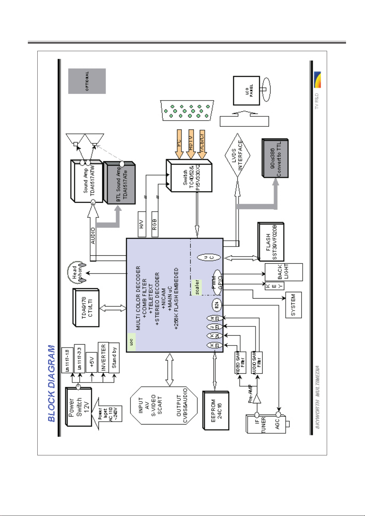
Chassis Block Diagram
-9-
Page 10

Service Adjustments
1. Preface
This Adjust Manual is only used for 8T84 LCD TV.
2. Specify
2.1 This TV operates onDC supply ,so through AC- DC ADAPTER to socket at
the back of the TV.The power is +12VDC.
2.2 Insert the mains plug in the wall socket having a mains voltage of 100~240V AC, 50/
60Hz.
2.3 Working condition: if no show clearly, work in the following state:.
1) Tempurature : 25 5
2) Relative humidity : 60% 20%
2.4 The receive set should be adjusted after working 20 minutes if no prior notice.
2.5 Equipments used
--- Multimeter
Max Input Current: Up to 1 A/Max input Voltage:500Vdc
Measurement Range: 10Mvr~100Vdc/Accuracy :0.03%
--- Oscilloscope:
Frequency band: up to 20M/input impedance: up to 1
Input Capacitance: Less than 30Pf/ Max Input Voltage:250V
--- PC
XGA(1024X768 60Hz)
2.6 Signal
60~80dBu standard color bar from Pm 5418 or from factory central signal generator is
used if no prior notice.
3. Software
Notice
software using in this chassis is stored in FLASH ROM. The flash ROM is re-writable.
Procedure relates to functions. Difference function chassis should be written differen
-ce edition procedure.
-10-
Page 11

Service Adjustments
4. Chassis check
4.1 The chassis should be clear and no short or open circuit, no missing components or
wrong components insertion.
4.2 Check the input and output pins of 12V,5V ,3.3V,1.8V , REGULATOR IC
(The C step of 8360,3430,8330,7096,7097),
4.3 Connect the chassis to LCD panel on the adjust equipment and power on, confirm
5V,3.3V, from the regulators are OK.
4.4. Confirm OSD is OK,blue ground appears is no signal.
4.5 Confirm remote control functions and all local keys control function are OK. The set
can enter standby states and exit to normal work status.
4.6 Confirm search function, store all factory signal, confirm picture and sound of any
pattern are Ok.
4.7 RF-AGC adjustment
Inputting the color signal of 70dB(VHF-H wave band),pressing the factory menu botton
to enter factory menu,adjusting RFAGC value to AGC voltage=2.7V which is in one pin
of tuner.
4.8 Confirm sound and picture of SCART is ok at input and output,the sound and
picture of YUV and PC are ok at input.
4.9 After complete assembly set TV to snow dot mode to aging line.
5. Complete check
5.1 Confirm H,V repeat rate and liner are OK in every state picture of TV,AV PC and so on.
5.2 Check white balance(adjustment)
5.3 Check picture and sound in all the TV mode
the weak and strong signal; ch
5.4 Confirm NICAM function is OK.
5.5 Confirm Teletext function is OK.
5.6 Confirm sound and picture of SCART is ok at input and output,the sound and
ck picturein low and high voltage power input mode.
e
CONFIRM
are OK. Check picture and sound under
NO SHORT CIRC
-UIT TO Gnd.
picture of YUV and PC are ok at input.
5.7 Confirm remote control and local control functions are OK,we can set the TV to standby
mode then normal mode to confirm if the set can work properly.
6. Final setting
6.1 PICTURE :MOVIES
6.2 VOLUME :30
6.3 BALANCE :0
6.4 CCD : OFF
6.5 SLEEP TIME :0
-11-
Page 12
Control Location
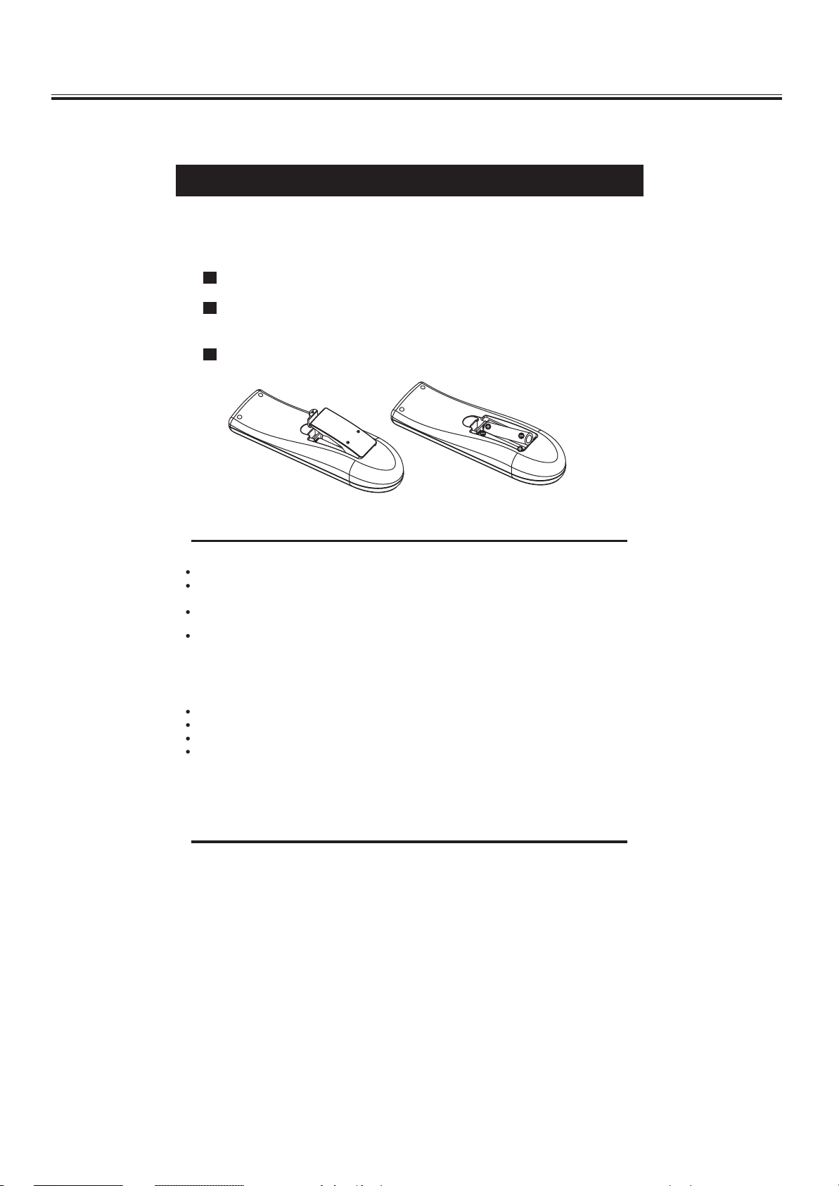
Insert The Batteries
1
Remove the battery cover by pressing it and sliding it down.
2
Insert the two 1.5V (AAA size) batteries making sure the polarity (+ or -) of the
batteries matches the polarity marks inside the unit.
3
Replace the battery cover by sliding it in until you hear a click sound.
SETUP
Precautions when using batteries
Do not use old and new batteries together.
Do not use different types of batteries (for example, Manganese and Alkaline
batteries)together.
Note that there are chargeable and non-chargeable batteries. Do not attempt to
charge non-chargeable batteries.
Remove the batteries from the remote control unit if you do not intend to use the
unit for a long time.
Precautions when using the remote control unit
Do not drop the remote control unit.
Do not subject the remote control unit to physical shocks.
Keep the remote control unit dry. Wetting it may cause the unit to malfunction.
Replace the batteries with new ones when operation of the unit deteriorates.
-12-
Page 13

Operation Instructions
FUNCTIONAL PARTS
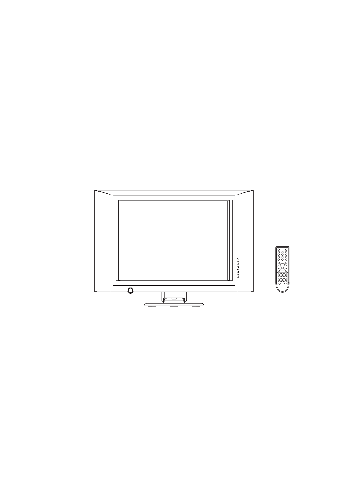
Front View of TV Set
1. Remote Sensor
2. Disp Button
3. TV/AV Button
4. Main Menu Button
5. CH.+Button
6. CH.- Button
7. VOL.+Button
8. VOL.- Button
9. Power Indicator/Stand by Button
10. Speakers
To turn the TV power ON
Put the TV set on the correct place, then connect the DC plug of the AC-DC adaptor
to the DC 12V socket at the back of the TV set. Connect the adaptor main cord to
the wall outlet, then the power indicator turns red and the TV set is at Standby Mode.
At Standby Mode, if Standby Button is pressed the power indicator will change to
yellow. It takes a few seconds before the picture appears.
1010
99
1010
11
22
33
44
55
66
77
88
To turn the TV power OFF
Press the Standby button to make the TV set in Standby Mode, then disconnect
the power plug from the wall outlet.
NOTE
If TV is powered on without signal received and NO operation is performed for
about 8 minutes continuously, the TV set will enter standby mode automatically.
For any inputs other than TV, the TV set will not enter standby mode automatically
without users instruction.
If you are not going to use this TV set for a long time, switch off the set using the
power switch on the TV set and disconnect the power plug from the wall outlet.
-13-
Page 14

Operation Instructions
Rear View of TV Set
1. Headphone
2. Antenna Input Socket (75Ohm)
3. SCART
4. AV Audio Right In
5. AV Audio Left In
6. Component Input
7. VGA Input
8. DC Input
11
HEADPHONE
ANT IN
SCART
33
44
AUDIO IN
R L
55
22
66 88
COMPONENT
77
VGA DC IN
NOTE
Precautions when connecting to other equipment.
When using external equipment with this TV set, please read the instruction
manual of the external equipment.
Switch off all power supplies to the equipment and TV set before connection.
Always ensure that the input and output terminals are correctly connected.
-14-
Page 15

Operation Instructions
Remote Control Unit
3
2
5
879
0
6
TV
4
-
/-
-
1
POWER ON ( ) button
Press this button to switch from standby to Power
11
On mode.
2
SLEEP( ) button
Press this button to set the sleep timer.
When the preset length of time has passed,
the TV set enters standby mode.
Q.
VIEW
66
I/II
44
33
S.M.
INDEX MIX C.S
REVEAL CANCEL PC.ADJUST
SIZE SUB.PAGE SLEEP
HOLD ZOOM
PROG.+
MENU
PROG.-
TV/AV
VOL.+VOL.-
P.M.
CLK/LAGE
R
G
XX
Y
C
3
SOUND MODE SELECTION
(S.M.)
Press this button to select one of four soundeffects
with wrap-arround.
55
4
STEREO/BILINGUAL SOUND( )
I/II
button (option)
When stereo program is received, press
22
this button to select STEREO or MONO.
When bilingual program is received, press
this button to select DUAL-1, DUAL-2 or
MONO.
Mode Description
STEREO
MONO
DUAL-1
DUAL-2
Stereo mode.
Mono mode.
Multi-sound channel for language 1.
Multi-sound channel for language 2.
When the symbols of DUAL and STEREO change
yellow, it means TV input signal is FM; When the
symbols of them change red, it means TV input
signal is NICAM.
5
PROGRAM UP / DOWN buttons
PROG.+ PROG.-
Press these buttons to select channels in
ascending or descending order.
VOL
6
VOLUME UP / DOWN buttons
+
VOL
-
Press these buttons to adjust the volume level
up or down.
-15-
Page 16

Operation Instructions
Remote Control Unit
77
3
2
5
879
0
PROG.+
MENU
PROG.-
XX
6
TV
TV/AV
VOL.+VOL.-
P.M.
CLK/LAGE
R
G
Y
C
1111
1010
88
4
-
/
-
-
Q.
VIEW
I/II
S.M.
INDEX MIX C.S
REVEAL CANCEL PC.ADJUST
SIZE SUB.PAGE SLEEP
HOLD ZOOM
7
MUTE( ) button
Press this button to mute or restore sound.
8
QUICK VIEW
button
Press this button to return to the previously
viewed program.
9
PICTURE MODE PICTURE MODE(P.M.) button
Press this button to select the preset one of
the five picture mode with wraparound.
STANDARD
MILD
User preset picture mode.
Middle contrast and middle brightness level.
Highest
contrast and
Low contrast and low brightness level.
High contrast and igh
High
H
est
Picture Mode Description
99
PERSONAL
STANDARD
DYNAMIC
MILD
RICH
10
DIGITAL Button
PERSONAL
RICH
This TV allows you to select channels from
99.
0 to
Press this button to select one-digit, twodigit or three-digit channels input options.
To select a one-digit channel (e.g. Channel
8), press this button to change
--/---
channel selection to "-" on screen display
and press the "8" button only.
To select a two-digit channel (e.g. Channel
28), press this button to change
--/---
channel selection to "--" on screen display
and press "2" and "8" buttons.
To select a three-digit channel (e.g. Channel
128), press this button to change
--/---
channel selection to "---" on screen display
and press "1" , "2"and"8" buttons.
DYNAMIC
brightness
rig htn ess
b
level.
level.
11
CHANNEL SELECTION buttons
Press the number buttons to select a channel.
-16-
Page 17

Operation Instructions
Remote Control Unit
3
2
5
879
0
PROG.+
MENU
PROG.-
XX
6
TV
TV/AV
VOL.+VOL.-
P.M.
CLK/LAGE
R
G
Y
C
4
-
/-
-
Q.
VIEW
I/II
S.M.
INDEX MIX C.S
REVEAL CANCEL PC.ADJUST
SIZE SUB.PAGE SLEEP
HOLD ZOOM
12
MENU button
Press this button to enter the menu screens
for various optional adjustable settings.
AV/T V button
13
Press this button to switch among TV
broadcast, AV input program and other source.
With wraparound.
1414
1313
14
1212
TV
button
TV
PC
SCART
COMPONENT
Press the button to return TV state from Teletext or
from other source to enter the TV mode.(e.g. HD to
TV).
1515
15
DISP( )
button
Press this button to display the settings on
the screen. (e.g. Channel number for TV input,
1616
sound mode, colour system)
16
REDEFINE FUNCTION
R. In TV mode, press this button to change
the colour system.
G. In PC mode, press this button to adjust the
screen to the best station.
Y. Press this button to select a sleep time.
C. Press this button to change the picture size.
-17-
Page 18

Operation Instructions
TELETEXT OPERATIONS
For models with Teletext function only.
This page shows the function of the buttons on the remote control unit in Teletext mode.
3
2
5
879
0
PROG.+
MENU
PROG.-
XX
6
TV
TV/AV
VOL.+VOL.-
P.M.
CLK/LAGE
R
G
Y
C
-
Q.
VIEW
I/II
4
/
-
-
S.M.
11
33
22
77
55
88
99
INDEX MIX C.S
REVEAL CANCEL PC.ADJUST
SIZE SUB.PAGE SLEEP
HOLD ZOOM
1
PAGE NUMBER SELECTION
buttons
Press the number buttons to select a
Teletext page number.
2
INDEX button
Press this button to enter the Teletext mode.
+
3
TELETEXT PAGE UP
/ DOWN
Press these buttons to increase or decrease
PROG.-
PROG.
buttons
the Teletext page number.
4
COLOUR buttons
When entering teletext, press these hot keys to
response the corresponding colour actions which
displayed on screen.
These four buttons have some redefine functions
outside the Teletext mode (e.g.CS,PC.ADJUST,
SLEEP, ZOOM)
5
CANCEL
button
Press this button to appear the TV signal on the
background.
66
44
6
MIX
button
Press this button to close the teletext background.
1010
7
REVEAL button
Press this button to reveal the hidden information for
some Teletext pages (e.g. answers to puzzles or
riddles). Press again to hide the information.
SIZE button
8
Press this button to change the Teletext size.
9
HOLD button
Press this button to hold the Teletext page on
display to prevent the page from changing.
Press again to release the hold state.
10
SUB.PAGE
button
Subcode mod, gives, the possibility to select
certain subcode pages of a teletext page.
-18-
Page 19

Operation Instructions
2
4
5
6
879
-
/
- -
MENU
PROG.-
VOL.+VOL.-
AV/TV
0
3
PROG.+
Q.
VIEW
OK
I/II
P.M.
This TV set allows you to adjust general settings by selecting from the menu screens.
MENU SCREENS
Menu button
TV/AV
Brightness
Contrast
Colour
Sharpness
Colour temp.
Picture Mode
Zoom
Sharp
Cold
Personal
Auto
Press this button to display main menu, including Picture, Sound, Overview, Features, Installation
items. You can select them by pressing the VOL+/- buttons, and enter the submenu by pressing
PROG+/- buttons.
Picture menu
Enter Picture menu, you can select Brightness, Contrast, Colour,
Brightness
Contrast
Colour
Sharpness
Colour temp.
Picture Mode
Zoom
Sharp
Cold
Personal
Auto
Sharpness, Colour temp, Picture Mode and Zoom items by
pressing PROG+/- Buttons.
1.Brightness
Press the VOL+/- button to lighten/darken the picture.
2.Contrast
Press the VOL+/- button to increase/decrease the contrast of the
picture.
3.Colour
Press the VOL+/- button to increase/decrease the colour
saturation.
4.Sharpness
Press the button to sharpen or soften the picture.
The choices are Sharp , Sharpest , Auto , Softest , Soft ,
" "
Normal .
" "
" " " " " " " "
5.Colour temp.
Press the button to select a suitable colour temperature to display.
The choices are Warm , Normal , Cold .
" "
"
" " "
6.Picture Mode
Press the button to select the next picture preset setting with wrap
around and set the values brightness, colour, contrast and sharpness.
-19-
Page 20

Operation Instructions
Press the button to adapt the picture size to the received picture.
The choices are Auto , Normal , Expand , Compress ,
Amaronap with wrap arround.
" "
Press MENU to switch the menu on/off.
8.Zoom
" "
" " " " " "
Sound menu
Volume
Balance
Bass
Treble
Sound Mode
Equalizer
Headphones
Personal
100 300 1k 3k 8k Main
Enter Sound menu, you can select Volume, Balance, Bass, Treble,
AVL, Surround, Sound Mode, Equalizer and Head phones items
by pressing PROG+/- Buttons.
1.Volume
Press the VOL+ or VOL- button to adjust the sound volume.
2.Balance
Press the VOL+ or VOL- button to adjust to the left to right sound
channel volume.
3.Bass
Press the VOL+ or VOL- button to adjust the bass boost value.
4.Treble
Press the VOL+ or VOL- button to adjust the high frequency signal
value.
5.Sound Mode
Press the button to obtain special soundeffects.
The choices are Personal , Speech , Music and Theatre
"
" "
"
"
"
" "
with wrap arround .
8.Equalizer
A tone control system designed to compensate for frequency
distortion in audio systems.
Enter Equalizer ,you can select 100HZ,300HZ,1KHZ,3KHZ
And 8KHZ items by pressing PROG+/- Buttons and change
the corresponding value of volume by pressing VOL +/- Buttons.
-20-
Page 21

Operation Instructions
9.Headphones
HP volume
HP balance
Program number and name menu
Enter Headphones, you can select Hp volume or Hp balance
items by pressing PROG+/- Buttons.
Press the VOL+/- Buttons to adjust the Headphones volume.
Press the VOL+/- Buttons to adjust the left to right sound
channel volume.
Press MENU to switch the menu on/off.
1
9
2
3
4
5
6
7
8
17
10
18
11
19
12
20
13
21
14
22
15
23
16
24
Move Delete
Features menu
Language
Country
Child lock
Timers
Teletext lang.
Teletext E / W
RT Clock
English
Gr. Britain
Pan European
West
Enter Program menu, you can select any number that you expect
by pressing PROG+/- and VOL+/- and every number delegates
corresponding channel.
1.Move button
The Green key on the RC (Remote control)will activate this function.
The first time it will select the program, which will be moved.
The text of the button is Select .
"
"
The second time will move the previous selected program to the
current position. The text of the button is Mode .
"
"
Any key can interrupt this action before the insert action is
initiated. The interruption will reset the move action but will not
leave the menu except for the Menu key.
2.Delete button
The Red key on the RC will activate this function.
The current selected program will be deleted.
Press MENU to switch the menu off.
Enter Features menu, you can select Language, Country,
Child lock, Timers, Teletext lang.,Teletext E/W and RT Clock
items by pressing PROG+/- Buttons.
1.Language
Change the user interfuse language in one out of 3 languages
" " " " " "
( English , French and German )with wraparound.
2.Country
Select the country which ATS use to sort the program.
-21-
Page 22

Operation Instructions
3.Child lock
Lock
Lock code
Sleep timer
Reminder timer
Off timer
Switch timer
Switch program
Timer
On
0000
5
115
12:05
08:23
2
11:30
Enter Child lock, you can select Lock or Lock code items by
pressing PROG+/- Buttons.
The child lock function allows users to prevent their children from
watching unsuitable programs. There is an overall chile lock
mechanism, which the user can enable or disable. Besides, each
program can be protected by the child lock function individually.
Some menus are also protected by the child lock function.
The same code must be applied to unlock the screen.
If the correct code has been entered, then the screen will
be unlocked. The video and audio will be de-muted and the
program will be visible and audible.
NOTE: The default lock code is 0000.
If forget the user code, the skeleton key in 4711.
4.Timers
The user-controlled timers are the Sleep timer, Reminder timer, Off
timer, Switch timer, switch program and timer.
1)Set Sleep timer
Set the Sleep timer value (in minutes) with a maximum of 120
minutes. The sleep timer can be set to any value of the following
sequence: Off - 120minutes with a resolution of 5minutes. When
this function is enabled, Display Sleep timer in the last 60 secretary
before expiration.
2)Set Reminder timer
The set Reminder timer function allows users to set the Reminder
timer with a resolution of 5 min and with a maximum of 120 minutes.
3)Set Off timer
Set the Off timer value (in hours:minutes). When the Real-time
Clock is disabled the entered Off time is relative, meaning that the
event is generated when the entered time has counted down to 0.
When enabled, the absolute time is entered, which means that the
event is generated when the entered Off time equals the current
time.
The set Off timer function allows users to set the Off timer in the
12 hours format HH:MM AM/PM or the 24 hours format HH:MM.
4)Set Switch timer
Set the Switch timer value (in hours:minutes). When the Real-time
Clock is disabled the entered Switch time is relative, meaning that
the action is invoked when the entered time has counted down to
0. When enabled, the absolute time is entered, which means that
the action is invoked when the entered Switch time equals the
current time.
5)Set Switch program
Set the program to switch to when the Switch timer expires
6)Set Time
Set the time for the Real-time Clock in the 12 hours format HH:MM
AM/PM or in the 24 hours format HH:MM.
"
"
"
"
-22-
Page 23

Operation Instructions
Clock
Timer
24Hrs
11:32
NOTE: When the main power is removed, the RT clock will be
reset to 1200AM.
5.Teletext lang.
The choices are Pan European , Cyrillic and Greek .
"
" "
"
"
"
6.Teletext E/W
"
""
The choices are East and West .
" "
7.RT Clock
Enter Time, you can select Clock or Time items by pressing
" "
" "
PROG+/- Buttons and Clock is setted 24 Hrs.
Press MENU to switch the menu off.
Installation menu
Program nr.
Program name
Colour system
Sound system
Auto Search
Frequency
AFC
Skip
Lock
1
CCTV-5
PAL
BG
049.75 MHz
0n
Off
Off
Enter Installation menu, you can select Program nr.,Program
name, Colour system, Sound system, Auto Search, Frequency,
AFC, Skip and Lock items by pressing PROG+/- Buttons.
1.Program nr.
Press this button to find next/previous unskipped program or AV
soruce.
2.Program name
You can denominate any channel you enjoy by pressing
VOL+/- and PROG+/- Buttons.
3.Colour system
Press the button to select a new colour standard value in TV.
" "
The choices are PAL , SECAM , SECAM-L/L and Auto .
" " " " " "
4.Sound system
Press the button to select a new sound standard value in TV.
The choices are BG , I , DK , L/L and Auto .
" " " " " " " "," "
TV work in gear must the sound system correspond with the
colour system. The relator between them is following:
PAL - BG, DK, I
SECAM - BG, DK
SECAM - L/L
,
5.Auto Search
The auto search action takes care of program tuning, storing and
retrieving program information. In case of secam L/L the auto
,
search processing goes twice. When the maximum program
number(99) is stored autostore is cancelled. When ATS is enabled
in Feature menu setting, the programs will be sort.(see Feature
menu section)
-23-
Page 24

Operation Instructions
6.Frequency
Select a frequency between minimum and Maximum frequency(
115025mHZ to 863.25mHZ) by the digtal Buttons and VOL+/-
Buttons.
Press the VOL+/- Buttons to search the next or previous channel
manually.
7.AFC
Automatic frequency control. Once a transmitter is tuned, the
system will follow the signal by means of automatic following .
8.Skip
Press the skip to enable or disable the selected program from
being tuned to by pressing VOL+/- Buttons.
The choices are on and off .
9.Lock
You can select on state to lock the channel you expect by
pressing VOL +/- Buttons when the Child Lock selection is
enabled in features menu.
" "
" " " "
" "
Press MENU to switch the menu off.
-24-
Page 25

Operation Instructions
Other sources
SCART state
SCART
SCART menu
Brightness
Contrast
Colour
Sharpness
Colour temp.
Picture Mode
Zoom
COMPONENT menu
Language
Child lock
Timers
RT Clock
Sharp
Cold
Personal
Narmal
English
Press the TV/AV Button to select the SCART source or plug in
the scart to swith automaticly.
In SCART state, there are 3 geneal menus(Picture, Sound,
Feature) supported all function s are the same as in TV mode.
In component state, there are 3 geneal menus(Picture, Sound,
Feature) supported all functions are the same as in TV mode.
PC menu
Brightness
Contrast
Position
Video noise
Sharpness
Auto Adjust
Colour Temp.
Horizontal
Vertical
Sharp
11000K
When entering the PC mode, select the Picture menu, you can
select Brightness, Contrast, Position, Video noise, Sharpness,
Auto Adjust and Colour Temp. Items by pressing PROG+/-
Buttons.
Position
Select the Position sub menu, you can select Horizontal or
Vertical items by pressing PROG+/- Buttons.
The Position menu allows control of vertical and horizontal
position of the picture on the display.
Recommend: Don t changed theses values after auto adjust
,
at best.
,
-25-
Page 26

Operation Instructions
Video noise
Phase
Clock
Select the Video noise sub menu, you can select Phase or Clock
items by pressing PROG+/- Buttons.
The Video noise menu allows control of sampling phase and
clock to reduce visible video noise.
Recommend: Don t changed theses values after auto adjust at
best.
Auto Adjust
Start the auto-adjust procedure to automatically determine the
values for horizontal position, horizontal length, vertical position,
vertical length, phase adjust and clock adjust to the best status.
Colour temp.
Press the button to adjust the best visual effect of picture.
The choices are 11000k, 9300k, 8500k, 7300k, 6500k, 5500k.
,
Brightness, Contrast, Sharpness functions are the same as
functions in TV.
-26-
Page 27

1011
2
2
1
2
+1V8_1
2
2
2441
2
BLM21A102S
1
1
KEYB
5113
+3Vstb
1
1
+1V8_1
MUTE
U58
U41
1
1
2
100R
2
1
3337
D
2
112
100n 16V
2587
2
112
C
+8V
8271
8231
100NF
100UF
8232
10R
8230
8229
INDUCTOR
NM
8225
4.7NF
8224
R?
4k7
RES1
8222
IF
8221
75R
10NF
8223
1K
B
+8V
8240
8234
SIFF
4K7
8233
10NF
10NF
8220
8235
4K7
2717
8228
100R
8227
CAP
8238
MA858
2
C
SAW-SW
8237
1
B
4K7
E
8239
3
+8V
2
4K7
2
1
8246
1
SIFF
2
2
4K7
1
8247
8243
1
4K7
8245
L'-SW
112
1K
+1V8_1
BLM21A102S
5108
2
112
2467 220n 10V
2
112
2468 220n 10V
2
112
+3Vstb
5109
BLM21A102S
2
112
100n 16V
2586
2
112
+3Vstb
BLM21A102S
5110
2
112
2585 100n 16V
2
112
100u 10V
2445
2
112
100n 16V
2469
2
112
2
5p6 10V
2102
2
1
1017
2
1
112
XTALUOC
47R
3317
2
112
5p6 10V
2103
2
112
XTAL2LI
0R
3387
2
112
220n 10V
2470
2
112
DECDIG
5111 BLM21A102S
2
112
100n 16V
2584
2
112
100n 16V
2531
2
112
100u 10V
+5V_SW
2
4K7
2
1
8236
1
+8V
3904
+8V
2
8242
K
MA858
A
1
2
C
1
2
B
E
8244
3
2450
2
112
1K
3438
2
112
2
6n8 10V
2530
2
1
2583
2
2
100n 16V
112
5125
2
1
1020
K7257M
112233445
5
1019
K9650M
112233445
5
2
2
8241
1
NM
1
3904
3510
1u5 16V
2460
1
BILM21A102S
2
112
1
220n 10V
2527
2
3504
2
2
112
10u 10V
2459
1
47K
2
112
100n 16V
2526
1
2
112
Vdrb
10R
3593
2
112
1K
3505
4K7
3503
2
112
10R
3506
2
112
Vdra
2
112
2515
330n 16V
2
112
1M
3476
2
112
39K
3475
F1001
2
112
F1002
2
112
2
112
251110n 50V
2
112
AGC
680R
3474
2
112
100K
3473
T23
VSSP2
R23
VSSC4
R24
VDDC4
P23
VDDA3
P24
VREF_POS_LSL
P25
VREF_NEG_LSR+HPR
N23
VREF_POS_LSR+HPR
N25
VREF_NEG_HPL+HPR
N24
24.576Mhz
112
12K
VREF_POS_HPR
N26
XTALIN
M26
XTALOUT
M23
GND4
M25
VGUARDJSWIO
M24
DECDIG
L23
VP1
L26
PH2LF
L25
PH1LF
L24
GND1
2
K26
SECPLL
K25
DECBG
J26
EWDJAVL
J25
VDRS
H26
VDRA
K24
VIFIN1
K23
VIFIN2
G26
VSC
H25
IREF
J24
GNDIF
J23
SIFIN1JDVBIN1
H23
SIFIN2JDVBIN1
G25
AGCOUT
H24
EHTO
1
VDDA1
AE25
M15
VDDA4
P1_SJTX
2
1
1
1
2
2
1
1
AE24
P1_4JRX
100R
2
2
100n 16V
1
1
PC_DET
3450
2588
2
1
2
1
2
1
2
2
220n 10V
100R
2
1
2
1
100n 16V
5107
1
1
2466
3436100R
2
2
3389
2474
BLM21A102S
1
1
SAW_SW
AE23
AF23
AF24
AC23
AD23
VSSC3
VDDC3
P1_2JINT2
P2_4JPWM3
P2_SJPWM4
220u 10V
ASTB
2
2
1
10K
1K2
2
2
220n 10V
2
1
1
1
3451
3453
2472
2
1
1
2
2
2
2
2
10R
10K
100R
2
2
2
2
2
1
1
AD22
VSSCJP
1K
1
1
1
1
3449
3452
3447
3448 0R
3446
1
1
1
1
AE22
AF22
AD21
AC22
AC21
VDDC1
DECV1VB
P3_2JADC2
P3_1JADC1
P3_SJPWM4
1
2
2
3K3
2
+3Vstb
3K3
2
1
3512
7
1
3511
SCL
6
1
1
5
VGA_TV_SW
STATAV1
SECAM-SWSTATAV2
2
2
2
100R
2
100R
1
1
3455
3445
1
1
AF21
AE21
P3_0JADC0
P2_3JPWM2
SDA
2
YUV_TV_SW
BLM21A102S
2
1
5112
2
2
1
1
1
U11
2
2
U12
Reset
1
1
2
2
2
1
100R
100R
100R
2
2
2
2
220n 10V
1
1
1
1
3443
3224
3432
2471
2
1
1
1
AE20
AC20
AC19
AD19
AF20
AD20
P1_6JSCL
P1_7JSDA
P2_2JPWM1
P2_0JTPWM
P2_1JPWMO
VDDB_B183
5135
2
+3Vstb
112
BLM21A102S
1
7102
8
2
PCF85116T
2574
1
220n 10V
1
8
7
1
2
POWER ON/OFF
2
6
2
3
12SDi
12SD2
5
3
4
4
2
2
100R
2
2
1
1
3441
1
1
AF18
AF19
AE19
P1_3JT1
PO_1J2SDO1
P0_0J12SD11JO
12SWS
12SD1
+1V8_1
2
1
1
U13
2
22U14
ON_OFF
1
1
1
2
2
2
2
10R
100R
220R
10R
2
2
2
1
1
1
3440
3439
3434
3433
1
1
1
1
AC18
AE18
AD18
AD17
P0_3J12CLK
P0_4J12SWS
P0_2J12SDO2
L'-SW
2
1
1
1
22U15
22U16
1
2
10R
10R
2
2
1
1
3435
3333
1
AC17
VSSC2
VDDC2
+3Vstb
22U1
1
2591
U56
2
1
1
100n 16V
EXT_HSYNC_SEL
REMOTE
1
2
1
2
10R
5114
2
2
2
2
2
BLM21A102S
2
1
3334
100R
100R
1
100R
2
2
2
2
10K
1
1
1
1
1
3335
3336
1
3460
2
3463
2477
1
1
1
1
1
2
220n 16V
1
AA25
AA24
AA23
P11JTO
P1_0JINT1
INTOJPO_5
VREFAD_POS
VREFAD_NEG
L?A
2478
2
112
220n 10V
2
112
BLM21A102S
5115
2
2446
112
100U 10V
T16
VOD_ADC
VSS_ADC
VDDA2
VDDA
GNDA
VREFAD
VDDA1
BO
GO
RO
BLKIN
BCLIN
VP3
GND3
BJPbIN3
GJYIN3
RJPrIN3
INSSW3
VOUT
UOUT
YOUT
YSYNC
YIN
UIN
VIN
VDD_COMB
VSSCOMB
HOUT
FBISOJCSY
SVM
2
112
100n 16V
2479
T15
R16
2
112
2480
220n 10V
R15
P16
P15
N15
2
112
220n 10V
2484
N16
2448 100u 10V
2
112
M16
2
112
220n 10V
2481
Y25
2
112
3461100R
Y23
47p 50V
100R
3462
2
112
Y24
47p 50V
100R
3464
2
112
W23
2
112
W24
24861n 50V
2
112
47u 10V
2449
L16
L15
V23
V24
U23
U24
T26
T25
F26
E26
B14
A15
B15
D15
C15
A16
B16
B17
2
112
10u 10V
2453
BLN21A102S
2
BIN
112
2489100n 16V
2
GIN
112
100n 16V
2490
2
RIN
112
2495100n 16V
2
FBLIN
112
3513 100R
VOUT
UOUT
YOUT
100n 16V
2534
2
112
2535100n 16V
2
YIN
112
2536100n 16V
2
UIN
112
100n 16V
2537
2
VIN
112
100u 16V
2462
2
112
5126
BLM21A102S
2
112
2
112
2538100n 16V
47K
3519
2
112
Hout
10R
3521
2
112
SANDC
2
112
27K
3520
2
2
3327
10K
1
1
151413121110987654321
2575
2
112
100n 16V
+1V8_2
2
2576
112
100n 16V
5116
2
112
BLM21A102S
2447
112
112
2483
2
112
2482
2
112
2485
2
112
248747p 50V
5120
112
112
100n 16V
2488
2
1
2
1
+3Vstb
5117
2
112
BLM21A102S
112
100n 16V
100U 10V
100n 16V
BLM21A102S
2592
2
2
2577100n 16V
2
112
5118
2
112
+3Vstb
100n 16V
2578
2
112
5119
VDDA1
2
112
BLM21A102S
BOUT
GOUT
ROUT
100n 16V
2579
2
112
2
+5V_SW
2
+5V_SW
2581
100n 16V
16
D
+1V8_2
2
C
+3Vstb
B
REFOJREFIN
AUDIOIN5L
AUDIOINR
AUDOUTSL
AUDOUTSR
DECSDEM
QSSOJAMOUTJAUDEEM
GND3
PLLIF
SIFAGC
DVBJIFVOJFMRO
DVBOJFMRO
VCC8V
AGC2SIF
VP2
IFVOJSVOJCVBS1
AUDIOIN4L
AUDIOIN4R
CVBS4JY4
AUDIOIN2L
AUDIOIN2R
CVBS2JY2
AUDIOIN3R
AUDIOIN3L
CVBS3JY3
C2JC3
AUDOULSL
AUDOUTLSR
AUDOUTHPL
AUDOUTHPR
F25
F24
F23
E25
E24
E23
C24
B24
C23
C22
B23
C21
B21C4C20
B20
B19
C19
G24
A
1 2 3 4 5 6 7 8 9 10 11 12 13 14 15 16
SSIF
2
1
1
2
2
2
1
1
2509
2514
1
1
1
2
2
2
2
1
2093
1
1
1
2508
2
2
2
1
2
2
2
2
2
1
2
2
2
2
1
3471
3472
3485
2
1
1
1
1
3490
2
1
1
1
1
SCOL1
SCIR1
SCIL1
D24
D23
D22
D21
A23
1
1
1
1
1
2
1
1
1
24552u2 20V
2503
2
2
2
1
1
2
2505
1
2
1
3468
390R
2456
3n9 16V
2
2
2
1
4u710V
3469
3470
1
1
2
1
2506
2507
2
1
1
2
2458
2
SCOR1
2
1
1
2
1
2504
100n 16V
2
SOUT2
2457
2582
2
1
1
2
1
2502
2
2u2 2V
2
2
2
1
2580
2
2
3018
1
2
2
3019
1
1
2
2
3340
1
1
1
2
1
3467
2454
2
2
1
1
2
1
BLM21A102S
2500100n 16V
10u 10V
2
2
5121
1
CVBSO2
1
1
2
1
100n 16V
2
+5V_SW
SCIL2
1
2
1
1
1
2
2498
U2
U3
2094
1
1
1
2
2
2
2
1
2
2
1
1
1
2096
2097
2
2
2
1
2
2
3465
2
3341
3355
1
100R
100R
1
1
HDIL
HDIR
SCIR2
C18
A20
D19
D18
1
1
1
1
2
2
2
2
1
1
1
1
1
1
1
2099
2496
2098
2095
2
2
2
2
2
2
2
2
1
1
1
1
2510
2497
2100
2
2
2
2
2
2
2
2
3356
1
1
1
3466
100R
100R
1
1
PCIR
PCIL
Y1SCART
CVBSOJPIP
C17
C16
B18
D17
D16
2
2
2
2
2
2
1
1
1
1
3459
2
2
1
1
2475
2476
1
1
1
2
2
2
2
2
1
1
MOL MOR HPOL HPOR
2493
2494
2
2
Y2IN
C2IN
2
2
2
2
1
1
1
1
1
1
1
3456
3457
3458
1
3390
100R
2
2
2
2
1
1
1
1
1
1
1
2491
2
2
2
2092
2091
2492
POUT2
7103-1 SCALER
SCALER .SCH
Designer
checked by
approved by
Title
Number RevisionSize
E
Date: 29-Nov-2005 Sheet of
File: E:\ym\Doc\LOC\Main board\SCH \s ch1.ddb Drawn By:
A
Page 28

151413121110987654321
16
D
+3Vstb
+3Vstb
3508
2
DECDIG
112
10k
1
1
2
2439
2
10u 10v
3306
2
2
RESET
C
15
1021
141415
11
11
10
10
9
9
8
8
7
7
6
16
16
TDQ-6F6 TUNER
SECAM-SW
6
5
5
4
4
3
3
2
2
1
1
131312
12
8248
4K7
B
1
1
112
A1K
1
15k
2
2
BAS16
6050
2
1
2
1
3310
1
10.7
2
2
0R
2
1
3492
1
1
IF
3489
10R
2
SDA
112
SDA
2
SCL
112
10R
3488
3487
2
112
10K
6043
A1K
1n4148
1
2437
1
2
4.7u 6V3
2
8251
220UF
8250
NPN
2
2046
22n
2
1k
1
1
150k
1
6042
0R
A
1
1
BZX284-C33
2
K
2516
1
2
2
2517
3493
1
1
33n 50V
33n 50V
2
2
2
3494
2
1
112
47R
5124
2
112
BLM21A1028
1
+5V_SW
2
2438
1
2
4.7u 6V3
3491
2
27K
SCL
1
2
1
2
AGC
2
3486
2
120K
1
1
+5V_SW
8252
4K7
2
2
2
1
2
2
34312R2
3430
2
1
1
2
2529
1
1
3509
2R2
1
1
2
1
10K
220n 10v
2
E
1
B
C
2
7097
3
BC557B
C
1
B
E
7086
3
BC847B
2
2
1
2
2
2
2
1
2528
1
1
2
2
1
2R2
2R2
220n 10v
1
1
3428
3429
10k
1
3507
2
E
1
B
C
2
7096
3
C
1
BC557B
B
E
7085
3
BC847B
7121
2
BSH111
D
S
1
G
7120
2
BSH111
3
D
S
1
G
3
3307
5123
112
BLM21A102S
2521
3495
2
2
112
112
22R
10U 10V
2
3496
2
33K
1
1
5105
2
112
47u
2522
2
112
2
220n 50V
1
2518
2
4n7 50V
1
1
2
2523
1
33n 50V
2
2
2
3
3
1
6044
BAV99W
1004
2
+5V_SW
+3V3s_SW
+1V8_2
+1V8_1
2
2
5104
2
47u
1
1
1
B
7084
BC847B
1
HPOL
2
1
4
3
HPOR
4
3
6
5
MOL
6
5
8
7
MOR
8
7
10
9
10
9
12
11
12SCLK
12
11
14
13
14
13
16
18
20
FTCH-110-01-F-DV-K
+5V_SW
2520
2
112
4n7 50V
2
2
2519
1
2
C
4n7 50V
1
E
3
12SWS
15
12SDI
16
15
17
12SDI
18
17
19
12SD2
20
19
1
100n 16V
2
1
2525
5122
2
2
+5V_SW
112
BLM21A102S
1
3500
1
2
100K
2
3367
2
1
2
2524
112
B
112
10.7
1n 50V
330R
2
1
2
3499
3386
0R
1
1
2
150K
1
2
BLM21A102S
5127
2
+8V
112
2
112
7101
2461 10u 10V
TDA9178T/N1
2
112
20
2533 100n 16V
2
9178SANDC
SANDC
YOUT
2
3502
2
1
850R
1
2
112
2
21051n 50V
1
7089
C
1
BC847B
3391
E
2
1K
3
2
1
1
2104
2
1
1
3501
2
1n 0V
2
560R
2
2
20
2
10
10
15
112
2532100n 16V
15
12
13
2
1
112
1
23
0R
3315
24
2
3
112
3
8
100R
9
3514
2
4
112
4
11
100R
14
3515
2
5
112
16
5
100R
17
3516
6
6
19
21
7
7
22
18
18
1018
SFE10.7MS3A
11223
3
SSIF
2
2
3522
1
1K
1
2
12
13
23
24
8
9
11
14
16
17
19
21
22
UOUT
112
100R
3518
2
VOUT
112
100R
3517
SCL
SCL
SDA
SDA
2
112
3589
112
3590
112
3591
VIN
100R
2
UIN
100R
2
100R
YIN
1
1
1
2568
2
2
2
2570
2569
1
1
1
2
2
2
22pF 50V
22pF 50V
22pF 50V
D
C
B
A
1 2 3 4 5 6 7 8 9 10 11 12 13 14 15 16
TUNER .SCH
Designer
checked by
approved by
Title
Number RevisionSize
E
Date: 29-Nov-2005 Sheet of
File: E:\ym\Doc\LOC\Main board\SCH \s ch1.ddb Drawn By:
A
Page 29

FROM EARPHONE PIN7
D
C
B
HOUT
+VS
3530
10K
2543
A
33n 50V
Vdra
2596
+VS
2072
10uF/10V
HPOR
HPOL
2051
100PF
2052
100PF
54321
5V_HPhone
5V_PHone
3314
15K
2047
3346
5K6
470nF 16V
2049
3312
5K6
470nF 16V
15K
3363
3348
300R
3349
300R
1213A
WHITE
MOL
1
1
3
3
2
2
MOR
Amplifier .SCH
Designer
Checked by
Approved by
Title
Number RevisionSize
B
Date: 29-Nov-2005 Sheet of
File: E:\ym\Doc\LOC\M ain board\SCH\sch1.ddbDrawn By:
2050
2
3
2055
3362
6
5
2048
470nF 16V
1
1028
1
2
2
1
1034
1
2
2
Vamp
3570
2K2
2564
100n 16V
3
2
1
2567
1006
3358
3359
3360
3361
REMOTE
KEYB
2R/2W
18
17
8401
3
5
0R
10R
0R
10R
100n 16V
IN1+
IN2-
MODE
SVRR
1
1
5131
2
2
16
OUT1A
VP115VP2
OUT1B
OUT2A
OUT2B
SGND4PGND10PGND11HS
1213B
WHITE
4
3
2
1
+5V_SW
BLM21P300
2464 220u 16V
7098
TDA1517ATW
8
9
12
13
1
2
6
7
NC
14
19
20
21
4
5
6
TV_VS
TV_HS
1015
4
3
2
1
1015
5136
BLM21A102S
1005
3
2
1
1
4
5
6
1071
1
2
2
1
1070
1
2
2
3529 100K
Astb
SANDC
+3Vstb
MUTE
+VS
3525 18K
7078
8406
10K
3524
BC847B
3578
18K
2K2
3329
3526
8404
NPN
3577
+3Vstb
680R
3523
2542 680P 50V
VSYNC
9178SANDC
+12V
4K7
3575 18K
1K
10K
3328
8405
10K
1K
+5V-SW
4K7
3574
2562 100n 16V
2442 10uF 10V
2541
1n 50V
1
2
3
4
5
6
+12V_SW-2
5134
16
OUT1A
VP115VP2
OUT1B
OUT2A
OUT2B
BLM21P300
NC
3569
2K2
2465 220u 16V
7099
8
9
12
13
1
2
6
7
14
19
20
21
VORB
VSYNC
HOUT
HSYNC
1022
1
2
3
4
5
6
7
8
9
10
CON10
2443 100u 16V
+3Vstb
MOR
Vamp
3573
10K
100n 16V
7080
NPN
IN1
OUT1
IN2
OUT2
IN3
OUT3
14
7093
74HC14D
IN6
VCC
OUT6
IN5
OUT5
IN4
OUT4
GND
7
3572 10K
7079
5132
BLM21A102S
MOR
3576
NPN
+VS
13
12
11
10
9
8
3392 0R
3393
0R
3395
10K
2544 22P 50V
3366
47K
HOUT
680P 50V
2039
3568 4K7
HSYNC
1K
3330
3571
2K2
2K2
2444 100u 16V
+5V
+VS
C2IN
Y2IN
2566
2565
100n 16V
+5V_SW
XTALUOC
3394
47R
SCIR2
3
18
17
5
SCIL2
TDA1517ATW
IN1+
IN2-
MODE
SVRR
SGND4PGND10PGND11HS
XTAL2LI
HPLOUT
HPROUT
1 2 3 4 56
680PF 50V
3347
4
7200A
-
SO-08
+
+
8
680PF 50V
10K
4
-
+
+
7200B
SO-08
8
3350
3353
10K
10K
1
7
10K
6
2070
100uF/6V3
5V_HPhone
2071
5V_HPhone
3351
10K
3357
10K
100uF/6V3
2053
100PF
2054
100PF
HPROUT
D
HPLOUT
C
HDIL
B
HDIR
A
Page 30

54321
3531
300R
2
2
2545
1
100P
D
1066
1
SCOR1
2
2
1
1
3532
10K
1027
SCIR1
3533
2546
10K
100P
3550
300R
2
2
2554
1
100P
1062
1
SCOL2
6
D
3534
10K
2
2
1069
1
1
C
B
A
1 2 3 4 56
1001
1
1A
2
2A
3
3A
4
4A
5
5A
6
6A
7
7A
8
8A
9
9A
10
10A
11
11A
12
12A
13
13A
14
14A
15
15A
16
16A
17
17A
18
18A
19
19A
20
20A
21
21A
3540
100R
2
3541
2
75R
1031
1
1
2
2
1067
1
2106
47P
1
3548
100R
2
3546
2
75R
1035
1
1
SCIL1
3535
10K
2547
100P
2550
100P
3547
75R
3549
1K
2553
100P
2
1
GIN
Y1SCART
3539
100R
3536
2
75R
1029
1
2
3543
2
75R
1033
1
1
7087
NPN
3542
100R
BIN
2549
100P
3551
1K
2451
10u 10V
7095
PNP
2551
100P
RIN
3552
22R
2
2
1030
1
1
CVBSO2
3537
10K
3544
100R
2
3545
2
75R
1032
1
1
+5V_SW
STATAV1
3538
3K3
2548
100P
C
FBLIN
2552
100P
B
SCART .SCH
Designer
checked by
approved by
Title
Number RevisionSize
B
Date: 29-Nov-2005 Sheet of
File: E:\ym\Doc\LOC\M ain board\SCH\sch1.ddbDrawn By:
A
Page 31

54321
6
+5V-SW
8312
D
8321
470PF
8322
470PF
8319
INDUCTOR
8320
INDUCTOR
8317
1UF
8315
220R
8318
1UF
10R
8311
NPN
8310
1K
8314
2K2
SOUT2
D
C
8335
1
1A
3234
2
2A
3
1K
3A
4
4A
5
5A
3233
6
6A
7
1K
7A
8
8A
9
9A
10
10A
11
11A
12
12A
13
13A
14
14A
15
15A
16
16A
17
17A
18
18A
19
19A
B
20
20A
21
21A
3232
15K
2020
1N0
2019
1N0
2018
47P
2017
47U
3235
100R
SCIR2
SCIR1
3231
15K
3236
100R
3002
75R
3001
75R
Y2IN
C2IN
8306
75R
8307
CAP
8301
10K
+5V-SW
8304
8337
NPN
10K
8305
RES2
STATAV2
8302
3K3
8303
100P
8335
CAPACITOR
8336
4K7
POUT2
SCART .SCH
Designer
C
B
checked by
A
1 2 3 4 56
+5V-SW
approved by
Title
Number RevisionSize
B
Date: 29-Nov-2005 Sheet of
File: E:\ym\Doc\LOC\M ain board\SCH\sch1.ddbDrawn By:
A
Page 32

54321
6
3584
1 2
R4
R3
150R
1013
SKHH
A2
A1
K2
K1
D
C
1016
REF
REMOTE
3VSTB
KEYB
STOCKO-MKS 3470-04
2440
4
47U 6V3
3
2
1
+3V3STB
POWER ON/OFF
3
1
2
VS
OUT
GND
TSOP1836SS3V
+5V-SW
8408
4K7
7100
1016
SW001
1
2
1 2
3
4
SKHH
LED001
3583
180R
1012
1 2
SKHH
A2
K2
A1
LED002
K1
3582
240R
1074
1 2
SKHH
3581
330R
1010
1 2
SKHH
3580
470R
1009
1 2
SKHH
3579
680R
1008
1 2
SKHH
1007
1 2
SKHH
D
C
+3V3STB
B
B
REMOTE AND KEY .SCH
Designer
checked by
approved by
A
1 2 3 4 56
Title
Number RevisionSize
B
Date: 29-Nov-2005 Sheet of
File: E:\ym\Doc\LOC\M ain board\SCH\sch1.ddbDrawn By:
A
Page 33

54321
6
1
2
3
4
5
6
7
8
9
10
11
12
13
14
15
16
17
18
19
20
A(16)
A(14)
A(12)
A(10)
Designer
1271
+3V3-SW
DF14
A(17)
A(15)
A(13)
A(11)
A(9)
A(8)
RSTN_O
IAPMUTE
SCALER .SCH
1064
1
D(0)
D(1)
D(3)
D(5)
D(7)
2272
100N
1
2
3
4
5
6
7
8
9
10
11
12
13
14
15
2
3
D(2)
4
5
D(4)
6
7
D(6)
8
9
10
11
12
13
14
15
NM
1065
NM
D
C
B
RSN4
RSN3
RSN2
RSN1
RSN0
2271
3288
3273
3275
3277
3279
3281
2088
100N
10U 16V
+3V3S_SW
+5V_SW
SDA
+5V_SW
+5V
SCL
1K
3215
1K
2241
100N 16V
7211
NPN
7212
NPN
+3V3S_SW
3216
100K
BL_ADJ
+5V-SW
+12V-SW
3V3-SW
3221
1K
3263
0K
3222
RSN9
RSP9
RSN8
RSP8
RSN7
RSP7
RSN6
RSP6
RSN5
RSP5
BL_EN
4K7
3006
0R
3007
0R
3008
0R
3009
0R
3010
0R
3011
0R
3012
0R
3013
0R
3014
0R
3015
0R
1073
1
2
3
4
5
6
7
8
9
10
CON10
PSEN_ICE
WR_ICE
PSEN_6745
WR_6745
A(7)
A(6)
A(5)
A(4)
A(3)
A(2)
A(1)
A(0)
3214
3213
22K
IIC_SCL
1K
+5V
32991K3220
3219
2K
3264
47R
3352
47R
D
1211
1
2
3
4
5
6
B6B-PH-K
2213
C
B
100N 16V
2214
100UF/16V
3261
3262
1206
1206
+12V+12V_SW
1241
STOCKO 4P
2211
100N
3212
10E
2212
10U 16V
3218
10E
2215
100N
4
3
2
1
IIC_SDA
RSP4
RSP3
RSP2
RSP1
RSP0
3274
3276
3278
3280
3282
3271
3325
3272
1063
1
2
3
4
5
6
7
8
9
10
11
12
13
14
15
NM
checked by
A
1 2 3 4 56
approved by
Title
Number RevisionSize
B
Date: 29-Nov-2005 Sheet of
File: E:\ym\Doc\LOC\M ain board\SCH\sch1.ddbDrawn By:
A
Page 34

7654321
+1V8_PPLL
5004
2108
10u 10V
+3V3_PLL
2321 100n
5007
BLM21A102S
D
+3V3s_SW
+1V8_PLL
+1V8s_SW
VDDA_PPLL
+1V8s_SW
C
5008
BLM21A102S
5003
+3V3s_SW
BLM21A102S
B
+3V3s_SW
+3V3s_SW
+3V3s_SW
33852K2
LED_R_O
3316
A
+3V3s_SW
LED_G_O
+3V3_AVI
5006
BLM21A102S
2089
2090
2320
100n
100n
22u 10V
2337 100n
5010
BLM21A102S
+1V8_ADC
5009
BLM21A102S
2334
2335
2336
2107
5000
BLM21A102S
100n
100n
100n
22u 10V
2112
100n
+1V8_CORE
5011
BLM21A102S
2338
2339
2340
2333
2342
100n
100n
100n
22u 10V
100n
+3V3_LVDS
2397100n 10V
2399100n 10V
2398
100n 10V
+3V3_IO
2325
2329
2330
2083
2322
100n
100n
100n
100n
22u 10V
1058
1
KEY0
2
KEY1
3
LED_R
4
LED_G
5
CON5
3331
KBD0
1K
2057
2058
1nF
220pF
3332
15K
KBD0
3379
KBD1
1K
2059
2060
1nF
220pF
3378
KBD1
15K
3383
7105
PNP
1K
2064
2062
220pF
0R
220pF
3381
7106
PNP
1K
2063
220pF
33822K2
0R
3408
1 2 3 4 5 6 7 8
+1V8S_SW
+1V8S_SW
2317
100n
RAIN
GAIN
2343
2345
100n
100n
BAIN
2346
22p 10V
1060
CRYSTAL
2347
22p 10V
2
2599
112
100p
2084
100n
KEY0
FLASH_RST
A(16)
A(15)
A(12)
KEY1
A(7)
A(6)
A(5)
A(4)
A(3)
A(2)
A(1)
3380
150R
2061
220pF
A(0)
LED_R
A(0:17)
3384
150R
LED_G
2301
100n 10V
BLM21A102S
2302
100n 10V
+1V8_XTL
5005
2303
100n 10V
BLM21A102S
2304
100n 10V
322510E
2015
SCALER_R
33n 10V
2077
2038
10pF
FER_R
33n 10V
323047R
322610E
2016
SCALER_G
33n
2314
IN_SOG
22n
2078
2065
10pF
FER_G
33n
323847R
2310
331110E
33n
SCALER_B
2079
2311
10pF
FER_B
33n
324147R
+3V3_IO
33384K7
4K7
XTLOUT
XTLIN
XTAL2LI
3339
4K7
3342
4K7
3343
4K7
3344
4K7
3345
A(17)
A(14)
+3V3s_SW
FLASH_WR
337310K
2056
100nF
29
31
32
+3V3s_SW
7104
WE
A1730A14
VCC
3371
1
A13
RST
2
10K
A8
A16
3
A9
A15
4
A11
A12
5
OE
A7
6
A10
A6
7
CE
A5
8
D7
A4
9
D6
A3
10
D5
A2
11
D4
A1
12
D3
A0
GND16D215D013D1
14
D(0)
D(1)
D(2)
D(0:7)
U25
1
1
RSN9
U26
1
1
RSP9
U27
1
1
RSN8
U28
1
1
RSP8
U29
1
1
RSN7
U30
1
1
RSP7
U31
1
1
RSN6
U32
1
1
RSP6
U33
1
1
RSN5
U34
1
1
RSP5
+1V8_ADC
+3V3_AVI
+1V8_CORE
KBD0
F029
KBD1
1
1
A(17)
SCALER_B
FER_B
F001
1
1
SCALER_G
FER_G
+3V3_AVI
BI_ADJ
BL_EN
6745_RST
2080
INTX
100uF 10V
IAPMUTE
TCB_EN
A(13)
A(8)
A(9)
28
27
26
25
24
23
22
21
D(7)
20
D(6)
19
D(5)
18
D(4)
17
D(3)
3372
10K
FLASH_OE
+3V3s_SW
PSEN_6745
A(11)
A(10)
PSEN_ICE
WR_6745
WR_ICE
FLASH_OE
FLASH_WR
RSTN_O
+3V3s_SW
12K
3354
IN_SOG
SCALER_R
FER_R
+3V3_PLL
+1V8_PLL
AHSYNC
AVSYNC
VSCL
1056
1
2
3
CON3
1057
1
2
3
CON3
3374
100R
FLASH_RST
3375
100R
6745_RST
3376
4K7
WR_6745
3377
4K7
PSEN_6745
VDDA_PLL
J3
+3V3_IO
K4
VSS_CORE3
J2
VDD_IO0
H1
VDD_IO01
J1
KDB0
K2
KBD1
L4
PWM0
K1
A17IGPIO(11)
A1
NC45
A2
NC46
L3
VDD_CORE11
A10
NC47
A17
NC48
M2
VSS_CORE11
A18
NC49
A19
NC50
M3
VSS_CORE01
A21
NC51
A22
NC52
L1
LED_R_O
TXDIGPIO(6)
A24
193
L2
194
M1
195
N4
VSSA_RGB2
N3
IN_B
P4
REF_B
N2
VSSA_ADC_B
N1
VDDA1V8_ADC_B
P3
AVI_TEST
P2
VDD3V3_RGB1
P1
VSSA_RGB1
R3
IN_G
R4
REF_G
R2
VSSA_ADC_G
R1
VDDA1V8_ADC_G
T1
VDD3V3_IN
T2
VSSA_CLEAN
U1
VDD_CORE02
T3
RBIAS
T4
SOGIN
V1
VDD3V3_RGB0
U2
VSSA_RGB0
U3
IN_R
U4
REF_R
V4
VSSA_ADC_R
V2
VDDA1V8_ADC_R
V3
VDD3V3_LPLL
W1
VDD1V8_LPLL
W2
VSSA_CLEAN_LPLL
W3
VSSA_LPLL
Y1
AHS
Y2
AVS
AA1
ASCLIGPIO(14)
AA2
VSDALED_G_OIAPMUTE
PNL_PWRN
2
U59
6745_RST
INTX
AF9
G1
J4
F1
NC43
RST_N
VSSA_PPLL
VDDA_PPLL
INT_NIGPIO(7)
ASDAIGPIO(15)
RXDIGPIO(5)D1NC57
VDD_CORE12
NC3
AB1
AB2
AC1
D(0:7)
1
BL_ADJ
IIC_SCL
1
IIC_SDA
BL_EN
H4
H3
G3
F2
G2
NC42
SCLIGPIO(12)
GPIO(9)ACLK
SDAIGPIO(13)
IAPMUTE
AC2D7AD1D6AC3D5AE1D4AB4D3AE2D2AD3
D(7)
D(6)
D(5)
D(4)
U20
2
1
1
+1V8_XTL
XTLOUT
AVI_DET
1 U40
1
+3V3_IO
XTLIN
TCB_EN
E1
E2
AA3
F3
B3
D2
AE14
349E3350D3351F4352D4353E4354
NC42
NC41C4NC40B4NC39A4NC38C5NC37D5NC36
XTAL1G4XTAL0
VDD_IO1
VSS_CORE7
VSSA_XTAL
GPIO(3)ITEST
GPIO(4)IPWM1ITCP_TDO
VSS_IO0
NC54
D1
D0
VDD_CORE0
VSS_CORE0
245
246
247
248
249
250
251
A25
AF2
AF3
AF4
AF5
AC4
AE3
AD4
AC5
AE4
AD5
AE5
AC6
A(0)
A(1)
A(2)
A(3)
A(4)
A(5)
A(6)
D(3)
D(2)
D(1)
D(0)
A(0:16)
WR_6745
252
AD6
A(7)
PSEN_6745
+1V8_CORE
+3V3_IO
A5
A6
B6
C6
B7
D6
B5
L14
M14
B10
L13
C10
A11
B11
C11
+3V3_LVDS
7004B
L12
NC35D7NC34C7NC33D8NC32C8NC31A7NC30B8NC29A8NC28
VSS_IO3
VDD_IO3
VSS_CORE5
VSS_CORE4
VDD_CORE5
VDD_CORE4
253
254
255
256
257
258
259
260
261
262
263
264
265
AF6
AF7
AF8
AE6
AC7
AD7
AE8
AE7
AC8
AD8
AC9
AD9
AE9
A(8)
A(9)
A(10)
A(11)
A(12)
A(13)
A(14)
A(15)
A(16)
NC27
NC26A9NC25B9NC24
NC23
NC22
NC21
NC20
NC19
L11
RSN7
281
D10
RSN8
282
C9
RSN9
283
M13
284
D12
285
C12
286
B12
287
D11
RSP8
288
A12
289
A13
290
D13
291
D14
292
C13
293
M12
294
M11
RSP7
295
B13
296
D9
RSP9
297
C14
298
N13
RSN6
299
N14
RSP6
300
A14
301
N12
RSN5
302
N11
RSP5
N
P12
RSN4
304
P11
RSP4
305
P13
306
R11
RSN3
307
R12
RSP3
308
R13
RSN2
309
R14
RSP2
310
P14
311
T14
RSN1
312
T13
RSP1
T13
T11
RSN0
314
T12
RSP0
315
AE17
AE17
AC16
AC16
AD16
AD16
AE16
AE16
AF16
AF16
AC15
AC15
AD15
AD15
AE15
AE15
AF15
AF15
AF14
AF14
A3
326
AC14
327
AD14
328
AD13
329
AE13
330
AF13
331
Y4
332
266H2267
268
269
270
271
272
273
AF11
275
AD12
277
A
AF10
AF11
AF12
AC10
AE10
AC11
AE11
AC12
AE12
AD10
AD11
AD12
7103-1 SCALER
+1V8_CORE
+3V3_IO
Designer
checked by
approved by
Title
D
Date: 29-Nov-2005 Sheet of
File: E:\ym\Doc\LOC\Main board\SCH\sch1.ddbDrawn By:
8
D
C
B
SCALER .SCH
A
Number RevisionSize
Page 35

D
C
B
A
AVI_DET
+3Vstb
FTSH
2
1
4
3
6
5
8
7
10
9
3004
112
1K
2
3404
100K
+5V_SW
PC_HS
54321
1301
PHONEJACK STEREO
2
112
2110
112
1u0
1
A
2
B
3
C
1
3
5
7
9
1
B
2
3017
2
100K
1
1
2111
2
112
1u0
3403
2
2
112
1K
2109
2
2
112
1
1u0
3400
1
1K
2
2
2
2
1
1
2
1044
2
1
1
2
7005
C
NPN
E
3
2
1
B
2
3407
2
3
47K
1
1
3401
112
2
10K
3402
2
100K
1
1
PC Input .SCH
Designer
Checked by
Approved by
Title
Number RevisionSize
B
Date: 29-Nov-2005 Sheet of
File: E:\ym\Doc\LOC\M ain board\SCH\sch1.ddbDrawn By:
3284
112
10k
1043
3285
112
10k
7092
C
NPN
E
1
B
6046
BAV99W
1
+5V
PC_VS
PC_HS
+5V
6051
BAV99W1
2
1
1
2
3
3
3223
112
47K
1 2 3 4 56
+5V
1059
1-1470250-1
1
VRIN
2
VGIN
3
VBIN
4
4
5
2
5
6
6
7
2
1
7
8
8
VGA_V
VSDA
PC_HS
PC_VS
VSCL
9
10
10
11
NC
12
13
14
15
161617
2
2
1
1
1014
2
1
17
2
2
1
3
3
TV_VS
112
6045
BAV99W1
1
1
1045
2
2
2
2
1041
1040
1039
2
2
1
1
1
1
EXT_HSYNC
3
3
2
2
1037
1036
2
2
1
1
1
1
3266
3397
3398
3265
2
1042
2
1
1
VGA_TV_SW
EXT_HSYNC_SEL
3292
3399
3326
3324
TV_HS
2
2
2
2
327075R
326975R
1038
2
2
2
1
1
1
1
1
1
2
220R
112
2
100R
112
2
100R
112
2
220R
112
+5V
1
6047
1
3
2
2
BAV99W1
7116
10
0
9
1
6
G4
0R
12
2
112
112
112
112
2
328375R
2
1
1
0
0R
14
2
1
15
2
11
3
0R
1
2
0
0R
5
2
1
2
2
4
3
100R
3258
2
112
100R
3259
2
112
100R
3260
2
112
1
1
202812P
202712P
2
1
2
2
VSDA
VSCL
+5V
1
1
3
3
3
BAV99W
2
2
16
VDD
MDX
VEE
7
1
202912P
2
2
1
1
2
6048
2
1
2
1
2
100n
13
3
VSS
74HC4052D
8
TV_R
TV_G
TV_B
VGA_TV_SW
3365
112
0R
2036
112
BLM21A102S
3268
75R
TV_R
TV_G
TV_B
2
2
32983K3
32973K3
2
1
1
1
5139
112
3267
112
75R
P15V330W
2
3
5
6
11
10
14
13
1
15
2
33640R
2
1
1
2
+5V
U214
1
2
1
2
VS
1
2030
27P
2
1
2
1
2
1
2
2031
27P
16
7002
S1A
S2A
DA
VCC
S1B
S2B
DB
S1C
S2C
DC
S1D
S2D
DD
IN
ES
GND
8
221
U215
HS
221
4
7
9
12
AVSYNC
AHSYNC
EXT_HSYNC
5137
2
112
BLM21A102S
1
2034
2
100n
1
1U216
221
1U217
221
1U10
221
+5V_SW
RIN
GIN
BIN
RAIN
GAIN
BAIN
2
HD_Y
PC_VS
3016
112
100R
+5V_SW
1072
2
4
6
8
10
2
2
2
2113
112
1
1u0
3003
1
1K
2
2
6052
BAV99W
1
1
3
3
2
AVI_DET
6049
BAV70
1
1
3
7117
24LC21A
1
2
3
3
1
2
2037
1
100n
2
2
1
8
7
ADR0
WC
6
ADR1
SCL
5
ADR2
SDA
4
5138
2
2
1
2
2035
1
100n
2
112
BLM21A102S
2
6
2
2
PCIR
1
3287
2
2033
2
1
1
10k
2
100p
1
2
2
2
1
1
2
C
E
3
PCIL
1
3286
2032
2
1
10k
2
100p
+3Vstb
2
3406
2
10K
3405
1
100R
2
1
112
7088
NPN
D
C
B
PC_DET
A
Page 36

54321
5002
3237
4K7
D
C
B
A
ROUT
GOUT
BOUT
2067
10u 10V
3289
10K
3240
4K7
2068
10u 10V
3290
10K
3243
4K7
2066
10u 10V
3291
10K
1 2 3 4 56
BC847B
7108
BC847B
7109
BC847B
7107
2081
3250
270R
3257
270R
3248
270R
100n
3249
75R
3256
75R
2026
270P
3244
75R
2024
270P
BLM21A102S
+5V_SW
2025270P
3239
2085
10u 10V
2086
10u 10V
4K7
BC847B
7076
BC847B
7091
3370
100R
3369
100R
3227
100R
2021
33P
3228
100R
2022
33P
3304
10K
3251
4K7
3308
10K
RED1401-1
YKC21-4075
YKC21
BLUE1401-2
YKC21-4075
YKC21
1401A
1401B
2
1
2
3245
75R
1047
2
1
1
4
3
2
3246
75R
1048
2
1
1
YUV_TV_SW
5001
BLM21A102S
2042
100n
Designer
3303
2087
10u 10V
4K7
BC847B
7114
3005
100R
3368
100R
3229
2023
100R
33P
3309
10K
checked by
approved by
Title
B
Date: 29-Nov-2005 Sheet of
File: E:\ym\Doc\LOC\M ain board\SCH\sch1.ddbDrawn By:
GREEN1401-3
YKC21-4075
YKC21
1401C
6
5
2
3247
75R
2
1046
1
1
P15V330W
2
3
5
6
11
10
14
13
1
15
+5V_SW
P15V330W.SCH
Number RevisionSize
7003
16
S1A
S2A
DA
VCC
S1B
S2B
DB
S1C
S2C
DC
S1D
S2D
DD
IN
ES
GND
8
6
5140
BLM21A102S
2041
100n
+5V_SW
4
7
TV_R
9
TV_B
12
TV_G
D
C
B
A
Page 37

VCC
8361
LM2596
12345
8360
8364 8365 8367
D
1007
C
INDUCTOR
1
P
3
R
2
S
2434
MC78M08CDT
1
47u25V
7077
OUT3IN
GND
2
8363
INDUCTOR IRON
8372
8362
SCHOTTKY
+8V
2435
47u16V
0.1UF
+12V_SW
+12V
C?
CAP
R?
RES2
+5V-SW
8371
470UF
8402
3R/3W
+12V
+5V-SW
7118A
1
8
8
1
7
7
8414
10K
8415
NPN
7090
LM1117MP
3
IN
VOUT
10u 10V
3
100n 16V
7094
LM1117MP
IN
3
1
VOUT
1
2463
2540
+12V
GND
GND
OUT
OUT
7118B
+5V
ON/OFF
8413
4K7
+12V
2
4
2
4
5
5
3
6
6
+3Vstb
2075
2043
100n 16V
47uF6V3
+3Vs_SW
2571
2074
100n 16V
47uF6V3
+5V-SW
2539
100n
5129
BLM21A102S
+12V_SW2+12V_SW
8330 78L05
123
2082 100n
2254
10u 16V
54321
3
+5V
7001
LM1117MPX
IN
VOUT
1
GND
VCCVCC
6
2
OUT
+1V8S_SW
4
2014
47uF/6V3
VCCVCC
D
C
2045
100n
2
2
7113
BC847B
B
ON/OFF
3296
10k
3305
3k3
4
4
B
POWER .SCH
Designer
checked by
approved by
A
1 2 3 4 56
VCC
Title
Number RevisionSize
B
Date: 29-Nov-2005 Sheet of
File: E:\ym\Doc\LOC\M ain board\SCH\sch1.ddbDrawn By:
A
 Loading...