

ERIKS ECON Series Installation & Operation Manual

Installation & Operation Manual
Proven Quality since 1892
Content
1. ERIKS operating companies
2. Product description
3. Requirements for maintenance staff
4. Transport and storage
5. Function
6. Application
7. Installation
8. Maintenance
9. Service and repair
10. Troubleshooting
11. Removal
1. ERIKS operating companies
ECON ball check valves are being delivered by several ERIKS operating companies on a
worldwide basis. In this manual these will be referred to as ‘ERIKS’, the individual terms of
delivery of the ERIKS operating company having executed the order are applicable.
2. Product description
The ECON ball check valves are designed according to the information in our latest catalogue or
see our website www.eriks.com and should be used in accordance with the applicable pressuretemperature rating as stated on this website. ECON ball check valves are provided with casted
markings according to EN 19. The marking makes the identification of the valve easier and
contains:
- size (DN)
- pressure rating class
- body material marking
- arrow, indicating the medium flow direction
- ECON logo
3. Requirements for maintenance staff
The staff assigned to assembly, operating and maintenance tasks should be qualified to carry out
such jobs and in any circumstance, ensure personal safety
4. Transport and storage
Transport and storage should always the valve should be protected against external forces,
influence and destruction of the painting layer as well. The purpose of the painting layer is to
protect the valve against rust, during transport and storage. The valves should be stored in an
unpolluted space and should also be protected against all atmospheric circumstances. There
should be taken care of the temperature and humidity in the room, in order to prevent condensate
formation.
5. Function
ECON ball check valves are designed for the prevention of flow reversal. The operation of the
valve is fully automatic allowing liquid to flow in one direction only. The flowing medium presses
against the ball, thereby push them open. The ball check valve can be installed horizontal and
vertical (upward flow).
6. Application
ECON ball check valves use primarily in water purification stations, sewage treatment
installations, water supply facilities, pumping stations, etc. Application: for clean, waste and
sewage water and viscous media. The operation of the valve is fully automatic allowing liquid to
flow in one direction only. The installation designer is responsible for the check valve selection,
suitable for the working conditions. The valves are unsuitable, without written permission of an
ERIKS company, to apply for hazardous media as referred into Regulation (EC) No 1272/2008.
ECON check valves Fig. 2630-2631 www.eriks.com
Rev. 0
Installation & Operation Manual
Proven Quality since 1892
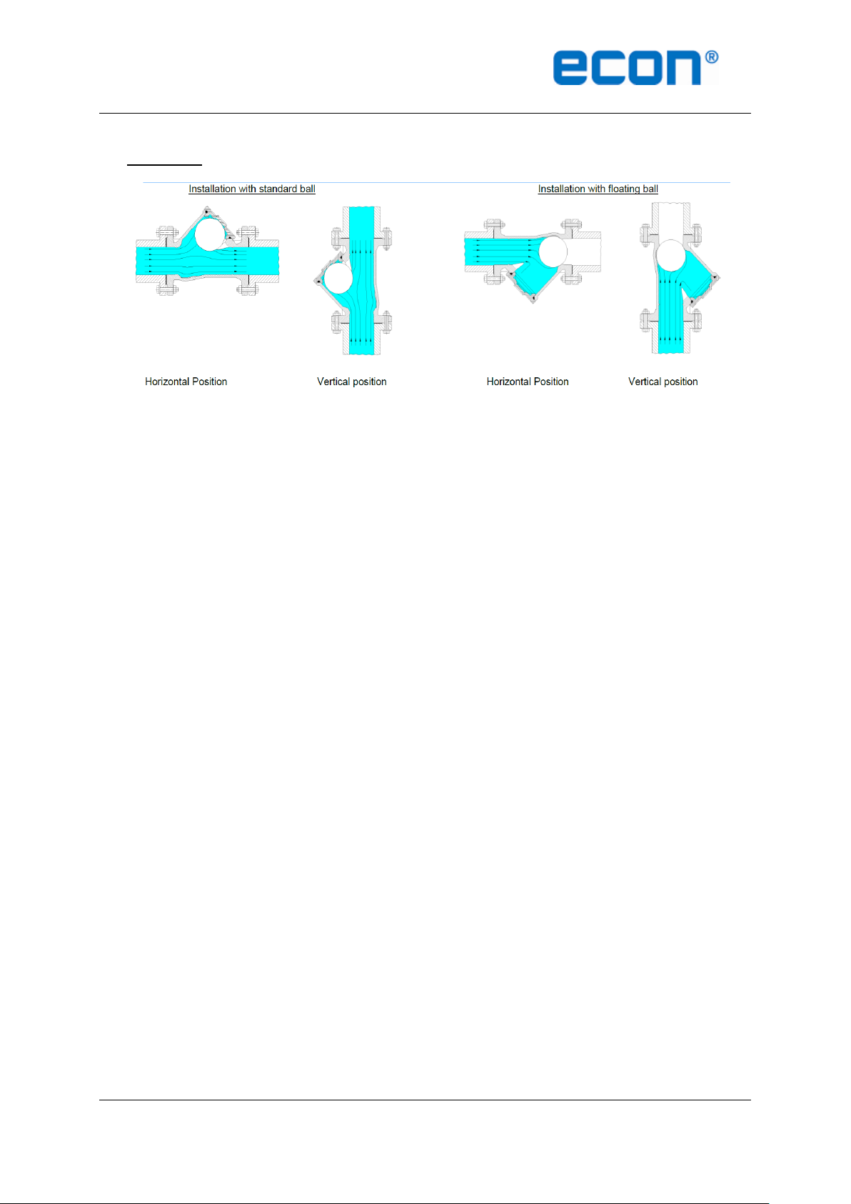
7. Installation
During the assembly of the ECON ball check valves, the following rules should be observed:
Make sure before an assembly that the valves were not damaged during the transport or
storage.
Make sure that the applied valves are suitable for the working conditions, medium used in
the plant and the right system connections, according to pressure and temperature limits.
When installing the ball check valves, ensure that the seat and the flange faces are
clean.
When valves are provided with lifting lugs, plates or eye nuts, these must be used to lift
the valve.
All special packaging material must be removed.
To ensure you use the correct sealing it is important to select the correct type of gasket
for the medium concerned, gaskets with the correct flange size must be used.
In horizontal pipelines the valve must be installed so that the bolted cover is facing
upward. (for version with sinking ball)
The valve must be installed with the direction arrow on the body coincident with the
direction of flow in the pipeline. For vertical pipelines the flow direction should only be
upwards.
Immediately prior to valve installation, the pipeline should be checked for cleanliness and
free of debris.
Valve end protectors should only be permanently removed prior to installation.
Place valve between pipe flanges, and insert the bolts.
Tighten bolts loosely.
Tighten bolts in a diagonal sequence to ensure flanges are pulled up parallel.
Finally tighten bolts to correct torque levels
Before plant startup, especially after repairs carried out, flash out the pipeline.
After installation it is necessary to check the valve operation and tightness of all
connections. A tightness test should be carried out.
Install pipelines so that damaging transverse, excessive vibrations, bending and tensional
forces are avoided.
ECON check valves Fig. 2630-2631 www.eriks.com
Rev. 0
 Loading...