

Erika C4000 Installation Manual
FORMATIC
Instruction Manual
Gibson Street, Leeds Road, Bradford
West Yorkshire, England. BD3 9TR
Telephone: +44 (0) 1274 668771 Fax: +44 (0) 1274 665214

FORMATIC
CONTENTS
1. Introduction
2. Technical Specification
3. Installation / Preparation for Production
4. Operating the Machine
5. Cleaning
6. Safety
7. Maintenance
8. Optional Extras;
10. Recommended Spares List
11. Wiring Diagrams
• Hoppers
• Conveyors
• Auto Wire Clean
• Paper Attachment

(1) INTRODUCTION
The Formatic range by Deighton Manufacturing (UK) Ltd guarantees accurate forming
and portioning of a wide variety of food mixtures and products.
Encompassing Retail, Commercial and Industrial sized models, the range has been
designed to accommodate the needs of both high and low volume producers.
Simplicity is the strength of the Formatic system. Suited to a variety of mixtures of
numerous textures and consistencies, the formatic uses synchronised paddles to gently
press mixture into the required form shape.
Assisted by the wire drum scraper, the formed product is then smoothly ejected onto the
conveyor, presenting it for packaging or further processing.
(2) TECHNICAL SPECIFICATION
Formatic

Retail Machine R1200 R2200 R3000
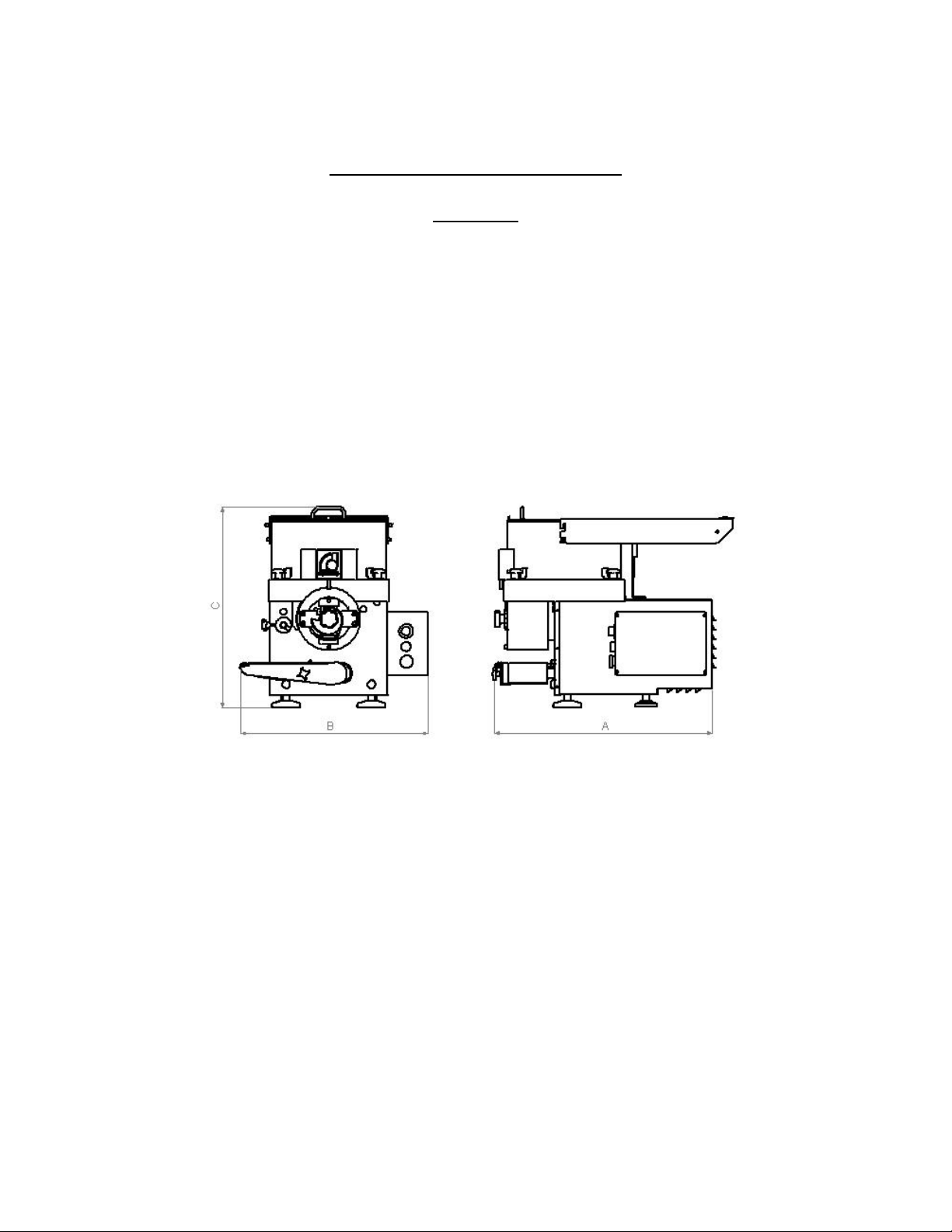
Size:
Length (A) 700 700 700
Width (B) 600 600 600
Height (C) 640 640 640
Weight:- 75 Kg 75 Kg 75 Kg
Product Output:- 1200/hr 2200/hr 3000/hr
Hopper Capacity:- 15 Kg 15 Kg 15 Kg
Product Size (max):- 125mm x 118mm x 24mm thick (34mm deep drop)
Electrical Supply:- 220/240V 50 Hz AC
Power:- 550 Watt 550 Watt 550 Watt
It should be noted that on certain products it is possible to increase the product out put by
specifying a 180 degree machine. This enables a form to be place on each side of the
drum and effectively doubling product output.

Commercial Machine C2000 C4000
Size:
Length (A) 700 700
Width (B) 800 800
Height (C) 700 700
Weight:- 90 Kg 90 Kg
Product Output:- 2000/hr 4000/hr
Hopper Capacity:- 20 Kg 20 Kg
Product Size (max):- 135mm x 135mm x 24mm thick (34mm deep drop)
Electrical Supply:- 220/240V 50 Hz AC
Power:- 550 Watt 550 Watt
It should be noted that on certain products it is possible to increase the product out put by
specifying a 180 degree machine. This enables a form to be place on each side of the
drum and effectively doubling product output.

Industrial Machine I4000 IR4000 I4000/50
Size:
Length (A) 800 750 800
Width (B) 850 600 850
Height (C) 700 725 785
Weight:- 100 Kg 90 Kg 150 Kg
Product Output:- 4000/hr 4000/hr 4000/hr
Hopper Capacity:- 30 Kg 15 Kg 30 Kg
Product Size (max):- 150 x 150 x 24 125 x 118 x 50 150 x 150 x 50
Electrical Supply:- 220/240V 50 Hz AC
Power:- 1500 Watt 1500 Watt 1500 Watt
It should be noted that on certain products it is possible to increase the product out put by
specifying a 180 degree machine. This enables a form to be place on each side of the
drum and effectively doubling product output.
(3) INSTALLATION PROCEDURE
3.1 Check the Formatic for transport damage and report any immediately to Deighton
Manufacturing Ltd.
3.2 Before Operating the machine:-
Remove any packaging material
Position the Formatic relative to any other equipment it is to connect with.
Connect the machine to the correct supply.
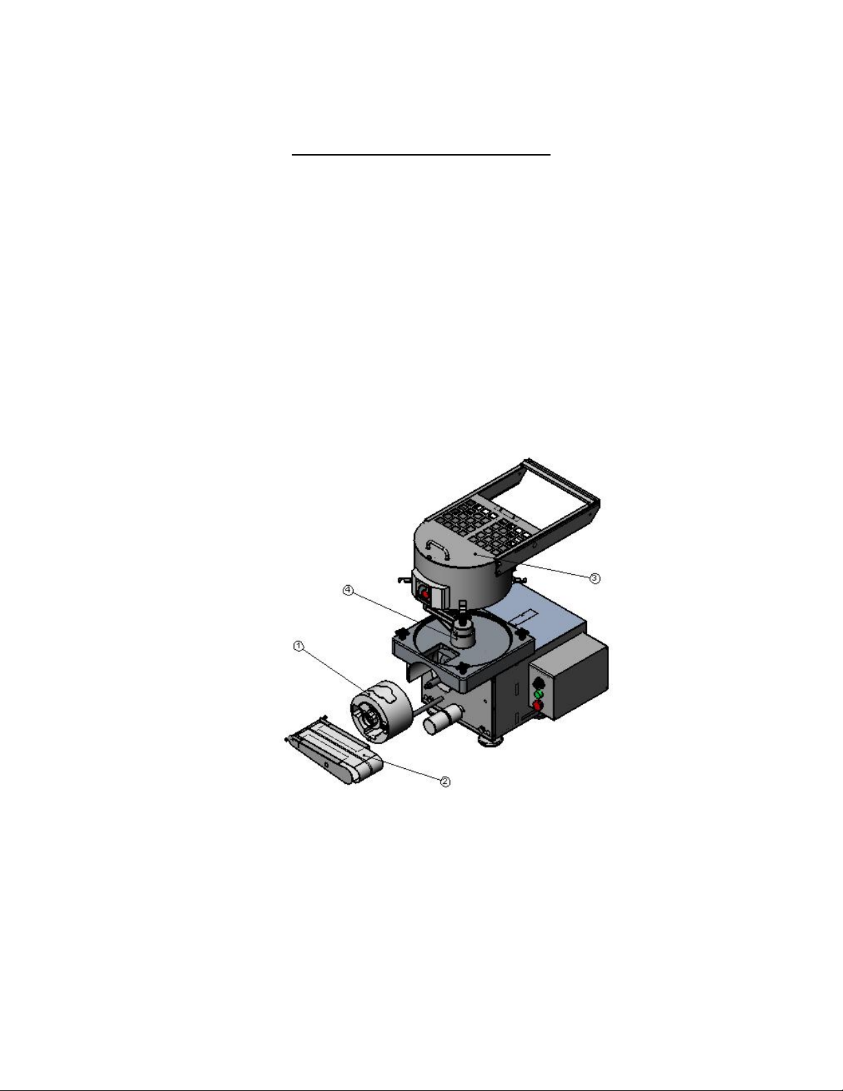
3.3 Step 1; Locate the selected drum onto the drive shaft ensuring that the
keyways are aligned and push the drum completely home (if the form is not at the
top you may need to lift the ejector set over the cam). Fit the paper cam/guard
over the drum on the end of the shaft and secure with locking knob (left hand
thread).

Step 2; Locate the conveyor platform onto the pivot shaft positioned to the
bottom left of the drum. Slip the conveyor belt onto the nylon drive roller and
around the platform nose roller, with the platform rotated to the 10 o’clock
position. Set the platform down so that it rest on the round conveyor stop and lock
in place using the hand knob provided. Fit the scraper wire assembly into the
support brackets on the nose of the conveyor and adjust the tension.
Step 3; Ensure the hopper sealing ring is pressed firmly into its retaining
slot in the machine top. Slacken the four hopper securing knobs on the top of the
machine. Place the hopper into the top machined recess on the hopper seal and
rotate such that the hopper securing lugs engage with the hand knob studs. Secure
the hopper in place by tightening the hand knobs.
Note: the hopper will only locate in one position with the hopper bars towards the
front right of the machine.
Always ensure the hopper is loaded correctly onto the seal in the hopper top.
Step 4; Position the chosen paddles onto the paddle shaft at the top of the
machine, ensuring the keyways are aligned, and secure in place with paddle knob.
Step 5; The scraper shaft assembly (not shown) locates into the housing on
the left hand side of the drum. Before assembling the scraper shaft, ensure that the
shaft locking screw is clear of the housing bore. Push home the assembly so that
the wire support bar nearest the front of the machine engages in the housing slot.
To ensure alignment in the housing slot it will be necessary to rotate the housing
clockwise with the aid of the locking screw. When in position secure with locking
screw.
The working position of the scraper, although factory set, can be adjusted with a
grub screw. This is located under a bung on the left hand side of the machine. The
tension of the scraper wire can be adjusted by rotating the front scraper bar hand
knob.
 Loading...