

Page 1

Installation, Operation
and Maintenance
Instructions
VM-3169B
VIBRATORY
FEEDERS
MODELS HD-46C, HD-56C,
& HD-66C
ERIEZ WORLD HEADQUARTERS: 2200 ASBURY ROAD, ERIE, PA 16506–1402 U.S.A.
WORLD AUTHORITY IN SEPARATION TECHNOLOGIES
Page 2

Introduction
This manual details the proper steps for installing,
operating and maintaining the Eriez Vibratory Feeder.
Careful attention to these requirements will assure
the most efficient and dependable performance of
this equipment.
If there are any questions or comments about the manual,
please call Eriez at 814/835-6000 for Vibratory
Feeder assistance.
CAUTION
Safety labels must be affixed to this product.
Should the safety label(s) be damaged, dislodged
or removed, contact Eriez for replacement.
© 2019 ERIEZ MAGNETICS ALL RIGHTS RESERVED
2
Page 3

Table of Contents
ERIEZ VIBRATORY FEEDER - MODELS HD-46C, HD-56C & HD-66C
INSTALLATION .....................................................................................................4
Mounting ......................................................................................................... 4
Electrical Connections .................................................................................... 4
OPERATION AND MAINTENANCE ...................................................................... 4
Tuning Guide ...................................................................................................4
Tuning for Non-Standard Trays ....................................................................... 5
Tuning for Different Conditions of Tray Loading .............................................. 6
REPAIRS ............................................................................................................... 6
Coil Replacement ............................................................................................ 7
Spring Replacement ....................................................................................... 8
Armature Replacement ................................................................................... 9
TROUBLESHOOTING ........................................................................................ 11
Vibratory Feeders
3
Page 4
Installation
Operation &
MOUNTING
This Hi-Vi model should be mounted on a flat surface,
fastened with bolts or screws of proper size. Use lock
washers under the bolt heads. to workers and damage
to property.
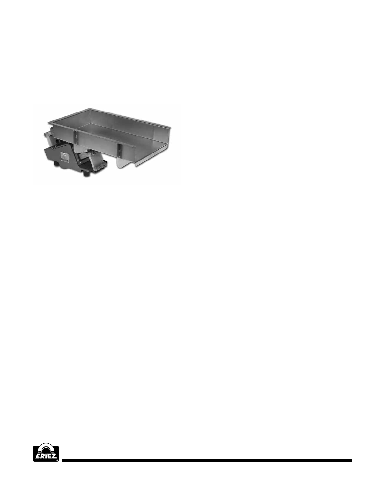
Model HD-46C
Figure 1
ELECTRICAL CONNECTIONS
NOTE: The Eriez Vibratory HD-C Feeder is designed to be
operated from an AC source through a special Eriez 30Hz
control (see IOM - 414). It cannot be operated from a DC
source. All wiring should conform to all applicable electrical
codes.
1. Check the specifications of the power line to be
certain that they are the same as those shown on the
nameplate.
Maintenance
Do not operate the unit with associated equipment
touching any part of the unit.
To start the feeder after all connections have been made,
apply power to the line connected to the feeder. If a
controller is used, operate the switch on the controller
and adjust the output voltage to maximum by rotating the
control knob to the full clockwise position. Ordinarily (at
ambient room temperatures) the unit will take about two
minutes to reach full steady-state displacement.
After full steady-state displacement has been attained,
use the controller to adjust the unit to the desired
feed rate.
No routine maintenance or lubrication is required,
except that any accumulation of foreign matter should
be periodically removed from between the tray-tiebar
assembly and the body, and from between the body and
the mounting surface, to prevent restriction of movement
of the vibratory elements.
IMPORTANT NOTE:
Special Trays and Attachments
Always consult Eriez before designing or constructing
special trays for your feeder drive. Also, contact Eriez
before modifying or attaching to any tray supplied by
Eriez. Changes made without Eriez’ prior approval will
void the warranty.
2. Connect the black and white wires in the Feeder power
cord to the power source or to the proper terminals in
the control box.
3. Connect the green wire to the ground or to the lug
provided in the control box.
4. If using a control box, make all connections as
indicated on the control wiring diagram.
5. Connect the lug in the control box to a good earth
ground (a cold water line is excellent).
6. On multiple drive feeders (two or more drives on one
tray) all drives should be wired electrically in phase
and in parallel. The black wires from each power
cord should be connected together and the white
wires connected together. The black wires should be
connected to the line side of the input voltage and the
white wires should be connected to the neutral side.
YOU ARE NOW READY TO START YOUR VIBRATORY
FEEDER.
TUNING GUIDE
General Information
The tuning means is provided solely for the purpose of
mechanically tuning the unit, with its tray, to the desired
vibratory displacement at full voltage. When a unit is
furnished complete with tray, it is properly tuned to the
tray at the factory. Such tuning is naturally somewhat
different for trays of different size or weight.
Tuning is accomplished by changing the stiffness of
the tuning spring stacks of the feeder (see Figure 2).
Variations in stiffness are obtained by changing the
number of springs in the stacks and/or by changing
the thickness of carbon fiber springs.
In normal operation at full voltage, the total displacement
for standard size trays, measured at the back of the tray,
is 9/64" to 11/64" (3.5 mm to 4.3 mm). For trays
substantially larger than standard this normal
displacement range should be reduced. Refer to the
serial number plate on your feeder for the amplitude that
your unit was tuned for.
4
Page 5
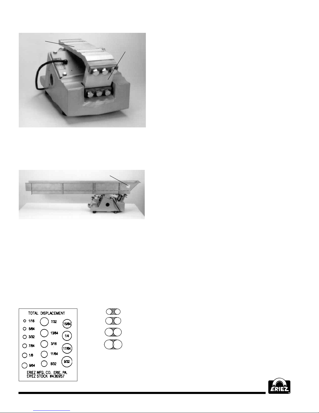
TIE BAR
REAR TUNING
SPRING STACK
Figure 2
How to Measure Displacement
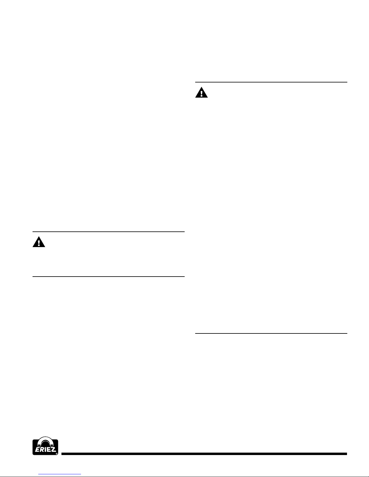
Position an Eriez displacement sticker on the outer side
of the tray, near the rear of the tray and at an angle of
25° from vertical (see Figure 3).
DISPLACEMENT STICKER
The following general rules, which apply only to the
Feeder operating ideally on the “normal” side of its
“tuning curve,” should be borne in mind when making
tuning adjustments to increase or decrease the
displacement:
1. 1. To DECREASE the tray displacement,
INCREASE the stiffness of the tuning springs.
2. 2. To INCREASE the tray displacement,
DECREASE the stiffness of the tuning springs.
If decreasing or increasing the tuning spring stiffness has
an opposite effect, it means that the spring stiffness is
great enough that the unit is operating on the “opposite”
side of its tuning curve. The spring stiffness should be
increased until the behavior is in accordance with rules 1
and 2. The unit can then be properly tuned to the desired
displacement.
As a guide to the stiffness of individual tuning springs,
each spring is marked with a code number example,
5-27. The first number (5) is the number of fiberglass
plies in the spring. The following number (27) indicates
the relative stiffness of the spring. The higher this
number the stiffer the spring.
Figure 3
Deflection (Displacement)
HD units are normally set at approximately 9/64-11/64
inch (3.5-4.3 mm) tray deflection. This can be checked
with an Eriez deflection sticker.
The sticker is read while the equipment is operating, by
looking at the optical illusion in which the printed circles
appear as double. Read the deflection where a pair of
circles just touch together.
A sticker is shown actual size in Figure 3B.
1/8
9/64
5/32
11/64
This is how the circles
would look if the tray
deflection were
5/32 [3.9 mm]
The total stiffness of the tuning spring stack is the sum of
the relative stiffness numbers. By various combinations
of different ply springs having different relative
stiffnesses, practically any desired total stiffness can be
obtained.
Note: Use 13 ply and lower springs. Do not use higher
ply springs as they will fail!
TUNING FOR NON-STANDARD
TRAYS
(Note : See “Special Trays and Attachments”)
If it is necessary to tune the unit for a non-standard tray,
follow this procedure:
1. Attach the tray, making sure that all lockwashers are
in place and the fasteners tight.
2. Energize the unit at the nameplate voltage and
frequency.
3. (a) During tuning if a hammering or striking noise
occurs when the unit is turned off and on quickly,
the displacement is well in excess of normal.
Whether striking or not, if the displacement exceeds
the normal range for that particular size of tray
(see Tuning Guide- General Information), it must
be reduced by substituting a tuning spring leaf or
leaves of less stiffness, or by subtracting one or
more leaves, until approximately normal full voltage
Figure 3B
Vibratory Feeders
5
Page 6
RepairsOperation and
Maintenance (cont.)
displacement is attained. Then use the controller
for fine or variable control of displacement and
feed rate.
(b) During tuning if the displacement at full voltage
is below the nominal range for that particular size
tray, and greater displacement is desired, increase
the tuning spring stiffness by substituting leaves of
greater stiffness or by adding more leaves.
TUNING FOR DIFFERENT
CONDITIONSOF TRAY LOADING
Units with Eriez-built trays are factory tuned for normal
displacement with light loading (light head load, light
materials, limited depth of flow of heavier materials).
Normal displacement for HD-46C, HD-56C and HD-66C
is approximately .209" to .219" (5.3 mm to 5.6 mm).
Ordinarily this tuning will not need to be changed. In no
case, however, should the unit be permitted to deflect
more than .219" (5.6 mm) without load for HD-46C,
HD-56C and HD-66C.
CAUTION
A small amount of striking during tuning is
permissible, but must not be allowed during regular
operation since damage to the feeder can result.
CAUTION: This unit contains Rare Earth Magnets.
Strong magnetic fields are present at assembly.
CAUTION - STRONG MAGNET
This equipment includes one or more extremely
powerful magnetic circuits. The magnetic field may
be much stronger than the Earth’s background field
at a distance several times the largest dimension of
the equipment.
• If you use a heart pacemaker or similar device
you must never approach the equipment
because your device may malfunction in the
magnetic field, with consequences up to and
including death.
• To avoid serious pinch-type injuries caused by
objects attracted to the magnet, keep all steel
and iron objects well away from the equipment.
Do not allow hands, fingers and other body parts
to be caught between the equipment and nearby
steel or iron objects.
• Keep credit cards, computer disks and other
magnetic storage devices away from the
equipment because magnetically stored
information may be corrupted by the magnetic
field.
• Keep electronic devices, such as computers or
monitors, away from the equipment because
exposure to the magnetic field may result in
malfunction or permanent damage to such
devices.
Contact Eriez if you have a question regarding these
precautions.
6
Page 7
COIL REPLACEMENT
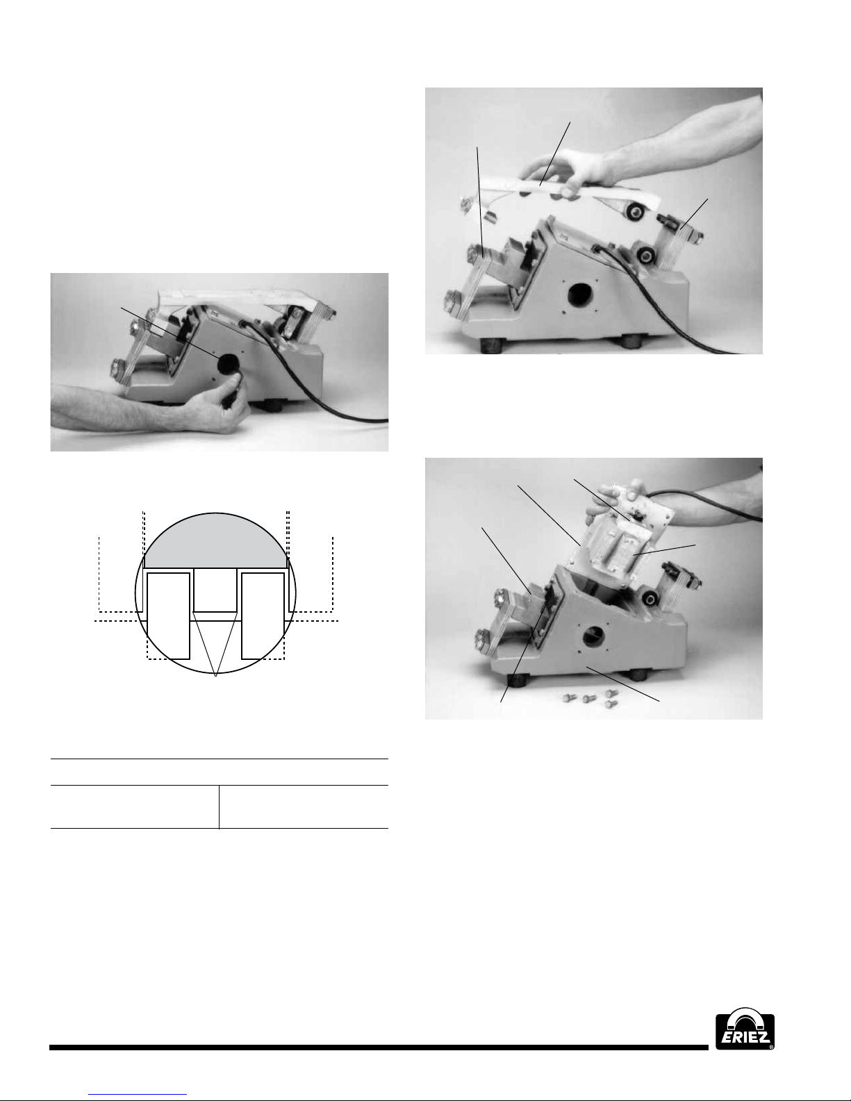
Refer to the Parts List Drawing and Figs. 4, 5, 6 & 7
The following procedure should be followed in
removing and replacing the electrical assembly,
which includes the coil:
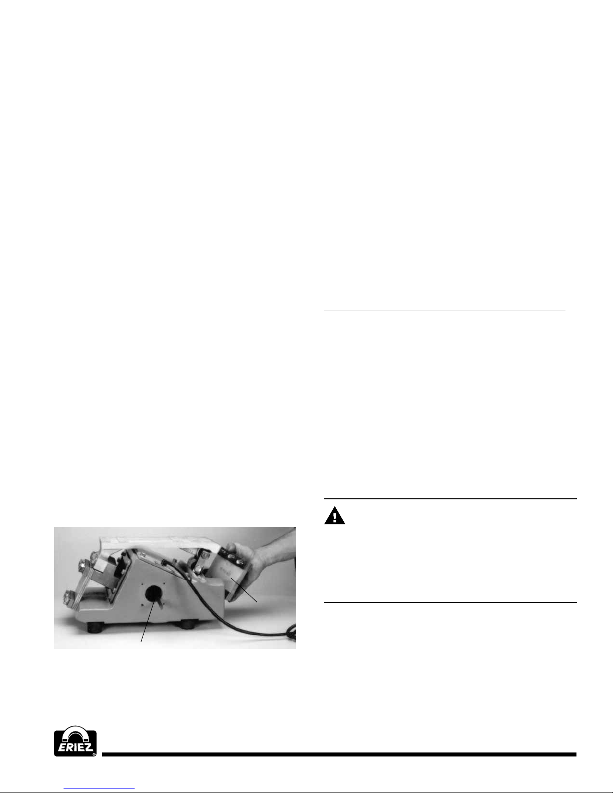
1. Remove both nameplates and insert the two
gap spacers (furnished with the unit) between
the E-frame center leg and the two armature
pole pieces (see Figure 4 & 5).
GAP
SPACERS
FRONT TUNING
SPRING STACK
TIE BAR
REAR
SPRING
STACK
Figure 6
3. Remove the bolts securing the electrical assembly
to the body housing and lift the assembly out of the
body housing (see Figure 7)
Figure 4
FIGURE 5
AIR GAP
.25
Figure 5
FEEDER AIR GAPS
HD-46C .25 HD-56C .25
HD-66C .25
2. Remove, in order, the bolts securing the
upper end of the rear tuning spring stack to
the tiebar. Lift the tray-tiebar-lever assembly away
from the body housing (see Figure 6).
ELECTRICAL
ASSEMBLY
SPRING
BAR
DIAPHRAGM
COIL
E-FRAME
BODY HOUSING
Figure 7
4. If the coil is defective, the entire E-frame assembly
including the coil must be replaced (order from Eriez
parts list).
5. In reassembling the unit, first center the armature
at the bottom of the body cavity; then insert the
E-frame into the body cavity, making sure that the
center leg enters the space between the armature
pole pieces. Insert the bolts securing the electrical
assembly and fasten only finger tight.
Vibratory Feeders
7
Page 8
Repairs (cont.)
6. Place the tray-tiebar assembly into its original
position and replace, in order, the bolts securing (a)
the lower end of the tiebar to the spring bar, and (b)
the upper end of the rear tuning spring stack to the
tiebar. Make sure that all tuning spring spacers are
in place and that all bolts are tight.
7. Loosen the electrical assembly bolts slightly and
roughly center the E-frame center leg between the
pole pieces. Insert the two spacers between the
E-frame center leg and the pole pieces and adjust
the electrical assembly forward or backward until
both spacers move freely in the gaps. Tighten
the electrical assembly plate and replace the
nameplates.
SPRING CHANGE OR
REPLACEMENT
Refer to the Parts List Drawing and Figs. 8 & 9.
If after inspection of the rear tuning spring stack,
the front stack is suspected, use the ARMATURE
REPLACEMENT procedure as a guide for reassembly
with special attention to the washer shaped spacers
between the spring bar and armature.
Carefully examine each tuning spring for signs of
delamination or breakage, especially in the area next
to the spring. A failed spring can be recognized by the
appearance of the spring surface. If this surface is
discolored or has a patchy whitish appearance, perhaps
accompanied by surface burying or other irregularity,
the spring is defective and should be replaced with a
new spring ordered from the parts list.
SPRING COMBINATIONS
Note: The front spring stack always remains the same
on the feeder and should not be altered when retuning
the unit. The following applies:
MODEL REAR SPRINGS/PLY FRONT SPRINGS/PLY
HD-46C 2-13 ply, 1-9 (2) 13 ply
Although the non-metallic springs used in the
Feeder have outstanding life characteristics, failure
may eventually occur, especially if the displacement
is greater than normal. The symptoms of such
failure will be:
1. Erratic behavior of the unit, or
2. Greatly reduced displacement.
If spring failure is suspected, the rear tuning spring
stack should be removed after first inserting the two gap
spacers between the center leg of the E-frame and the
two pole pieces (Figure 8). The purpose of this is to hold
the tiebar or tray-tiebar assembly in position while the
tuning springs are removed.
REAR TUNING
SPRING STACK
HD-56C 4-13 ply (2) 13 ply
HD-66C 5-13 ply (3) 13 ply
FEEDER DRIVE ONLY
(LESS TRAY SUPPLIED)
If a feeder is shipped without a tray, the standard rear
spring combination for the feeder is listed above. These
feeders will need to be tuned to the tray.
Refer to TUNING FOR NON-STANDARD TRAY section
CAUTION
Make sure that all of the fasteners in the
assembly are tight or torqued to spec at all times.
Periodic checks for tightness should be made to
insure against possible malfunction or damage due
to loose parts.
(See Table 1 Torque Chart)
GAP SPACER
Figure 8
8
Page 9
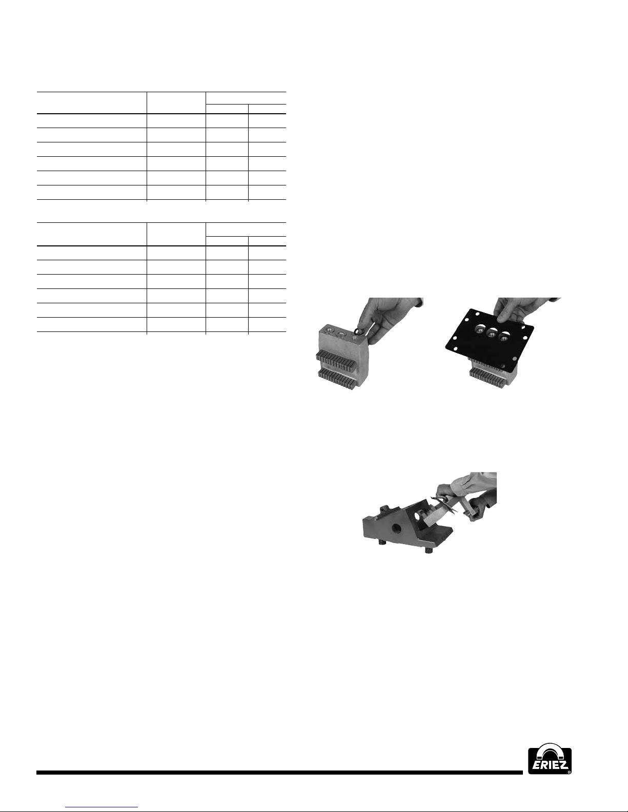
TABLE 1. TORQUE CHART
46 & 56 Series
Size
Rear Spring Bolts M14-2 11.8 85.3
Torsion Spring Bolts M12-1.75 7.4 53.5
Front Tie Bar Bolts M14-2 11.8 85.3
Front Spring Bolt M14-2 11.8 85.3
Electrical Ass’y Bolts M8-1.25 2.4 17.4
Tray Mounting Bolts M8-1.25 3.0 22
Part Bolt
Torque
m-kgs ft-lbs
66 Series
Size
Rear Spring Bolts M16-2 17.3 125
Torsion Spring Bolts M12-1.75 7.4 53.5
Front Tie Bar Bolts M16-2 17.3 125
Front Spring Bolt M16-2 17.3 125
Electrical Ass’y Bolts M8-1.25 2.4 17.4
Tray Mounting Bolt M12-1.75 7.4 53.5
Part Bolt
Torque
m-kgs ft-lbs
ARMATURE REPLACEMENT
Refer to the Parts List Drawing and Figs. 4, 5, 6 & 7.
5. Stand the armature and spring stack assembly on a
non-magnetic surface (I.E. wooden table) as shown
in Figure 9. NOTE: Keep armature away from any
steel parts and surfaces.
6. Loosen the bolts securing the spring stacks to the
armature and remove the spring stacks with the
bolts intact. Retain the washer shaped spacers
located between spring bar and armature. Note
the position of the elastomer diaphragm when
reassembling.
7. Center washer shaped spacers on tapped holes
of the armature. (Hint: using an instant adhesive
will keep the washers and elastomer diaphragm
in position while reassembling.) Position elastomer
diaphragm on the armature as shown in Figure 10.
Reverse the above procedure to reassemble
the unit.
CAUTION: This unit contains Rare Earth Magnets.
Strong magnetic fields are present at assembly.
Prolonged striking may damage the armature to an
extent that it will have to be replaced. If this should
become necessary, order a new armature from the
parts list and begin replacement by following the same
instructions as for coil replacement.
1. Continue by removing in order the bolts securing the
elastomer diaphragm clamp to the body housing.
2. Loosen slightly but do not remove the upper end of
the front tuning spring stacks to the spring bar and
the spring bar to the armature.
3. Loosen the bolts securing the lower end of the spring
stacks to the body housing leaving 1-2 threads in
the body housing. Carefully slide the spring stack
and the armature assembly back to the bolt heads
and remove the bolts from the body housing. (Do not
remove bolts from the spring stacks).
4. Remove the armature and spring stack assembly
by grasping the spring stacks and sliding it through
the opening in the body housing. NOTE: use a
downward pressure when removing this assembly
to keep the magnetic poles of the armature from
coming in contact with the body housing when going
through the opening.
Figure 9 Figure 10
8. Insert armature and diaphram assembly through
opening in front of base casting as shown in
Figure 11.
Figure 11
Vibratory Feeders
9
Page 10
NS NNS
AC
POWER
SUPPLY
POTENTIOMETER
ELECTRO-MAGNET
ARMATURE CONNECTED
TO SPRINGS AND
MOVING MASS
PERMANENT
MAGNET
Repairs (cont.)
9. Final assembly as follows:
• Check that the electrical E-frame and armature
assemblies are positioned with gap bars provided.
(Hand tight).
• Attach the tie bar to the rear of the body housing
using the existing rear tuning spring stack, and
bolts. (Tighten).
• Attach lever arm assembl.y. (Hand tight).
• Connect the tie bar to the front of the armature
adapter. (Torque - see Table 1).
• Check clearances. (Gap bars).
• Tighten front spring stack. (Torque - see Table 1).
• Tighten rear spring stack. (Torque - see Table 1).
• Tighten electrical E-frame assembly. (Torque - see
Table 1).
• Tighten lever arm assembly. (Torque - see
Table 1).
• Check all fasteners. (Check torque - see Table 1).
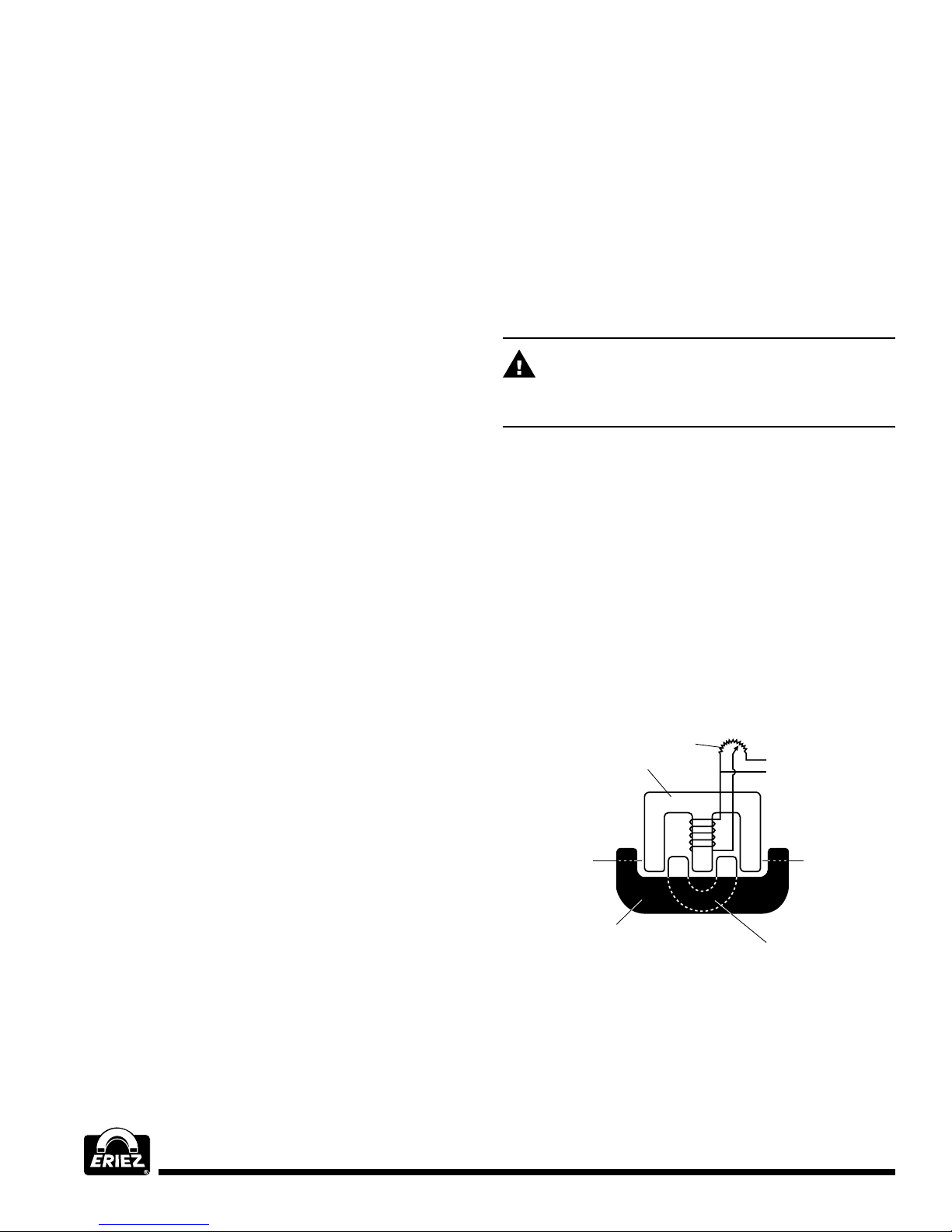
THE Hl-VI MAGNETIC DRIVE
CIRCUIT (RARE EARTH)
Old-style electromagnetic equipment has an inefficient
attract-release type operation, where a mass mounted
on springs is attracted by a DC electromagnet and
returned to its original position solely by the springs. The
new Hi-Vi method incorporates a lifetime permanent rare
earth magnet and is operated directly from an alternating
current line through Eriez 30Hz control.
accumulating to drive the armature in the same direction.
It also results in closing the magnetic circuit through the
electromagnet providing a magnetizing effect on the
permanent magnet on each side of the sine wave. The
demagnetizing force is very minor for the attracting force
and the magnetic lines of flux would much prefer to be
attracted than repelled. This always tends to place the
permanent magnet in a magnetizing circuit regardless of
where the AC current is on the sine wave. As the polarity
of the electromagnet changes, all of the forces are
reversed and the permanent magnet armature is driven
in the opposite direction.
CAUTION
Operation from portable engine driven
power plants.
Varying and unstable line frequency has a diverse effect
on vibratory feeders because they are tuned mechanical
devices, designed for 30 cycle operating frequency.
Shifts in the operating point due to changes in frequency,
(greater than 31 Hz or less than 29 Hz) can cause higher
than normal spring stress, striking and high line currents
which can cause drive and tray failure. When operating
from portable engine-driven power plants, be certain that
the engine is up to speed and all other loads are started
and at running speed before starting the electromagnet
feeder.
The feeder should always be stopped first when the
engine-driven power plant is shut down.
In the Hi-Vi method, the spring-mounted mass is
alternately both attracted and repelled by an AC
electromagnet assisted by the springs.
Intermeshing a fixed polarity permanent magnet with
an alternating polarity AC electromagnet eliminates the
rectifier since you would have an alternating attracting
and repelling force as the polarity of the electromagnet
alternated.
It will be noted that the pole pieces of the permanent
magnet are intermeshed in the air gaps of an
electromagnet. The polarity of the permanent magnet
is fixed; the polarity of the electromagnet alternates at
the line frequency. We have shown the polarity of the
electromagnet as it would exist on one side of the sine
wave. Note that both poles of the permanent magnet are
being attracted toward the unlike electromagnet poles.
They are also being repelled in the same direction by
the like electromagnet poles. This results in four forces
Figure 10
10
Page 11
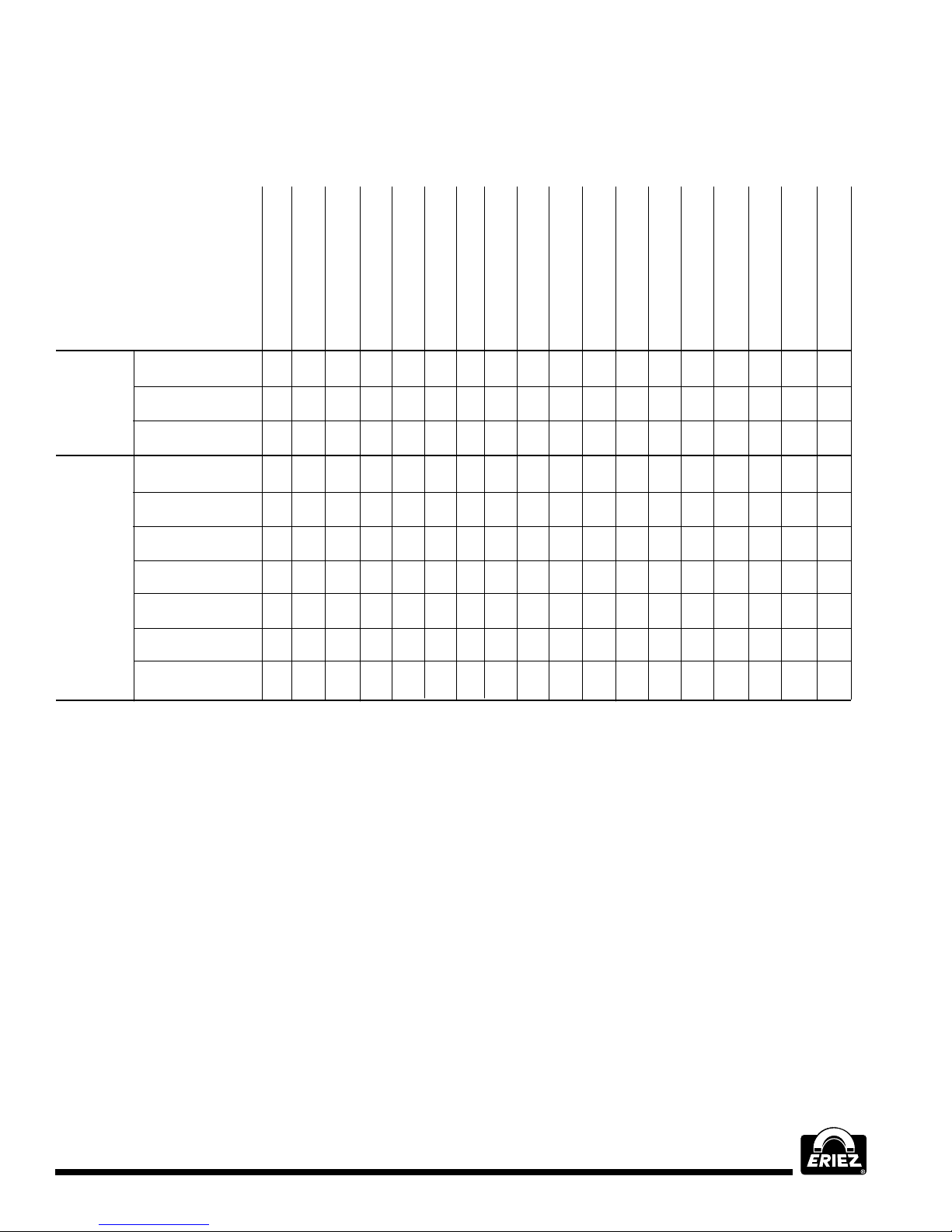
Troubleshooting
NATURE OF
PROBLEM
Misapplication
Tampering or Changing
of Base or Tray
Reduced or Low
Noisy but Output
Noisy Certain
Completely
Operating But
Output Okay
Gradual
Excessive
Turbulent
Develop After Satisfactory Initial
Inconsistent
Output
Okay
Periods Only
Inoperative
Reduced Output
Too Much Noise
Fading
Tray Wear
Flow
Initial Operation Installation
Output
1 2 5 6 7 8 9 11 13 14 16 19
2 3 8 9 10 11 12 13
11 13 14
2 4 5 7 13 15 16
2 3 5 6 7 8 9 10 11 12 13 14 16 19
2 7 8 9 10 11 12 13 14
18
10 11 14
2 3 5 6 7 9 10 11 12 13 14 16 19
TaBle 1 SERVICE CHART
Loose Spring Clamp or
Tray Mounting Bolts
Coil Failure
Control Failure
Incorrect Voltage
Spring Failure
5 7 8 9 10 13 19
Foreign Material Between
Tray & Reaction Mass
Incorrect Tuning
Poor or Broken
Weld on Tray
Incorrect Factory
Adjustment
Sympathetic Vibration
in Other Equipment
In Contact with
Other Equipment
Line Voltage
or Hz Variation
Blown Fuse or
Circuit Breaker
Other Electrical
Connections
Corrosive or
Abrasive Material
Product Variation
1. Misapplication
Feeder too small. Product difficult or impossible to
handle. Impossible temperatures or atmospheres.
Impossible dimensional requirements. Feeding
requirements too precise or excessive. Consult
Eriez.
2. Tampering or Changing of Base or Tray
Improper disassembly, extensions, covers, weights,
screens or other modifications or attachments
may have affected performance. Reassemble in
accordance with printed instructions or consult Eriez.
3. Loose Spring Clamp or Tray Mounting Bolts
Tighten all bolts.
4. Coil Failure
Replace coil or coil and E-frame assembly.
Order from Eriez parts lists. Follow maintenance
instructions carefully.
5. Control Failure
Check for burned out powerstat or rheostat,
defective capacitor, defective switch, loose wiring,
defective transformer (if used). Order new parts from
Eriez. Possibility special control needed. Consult
Engineering.
6. Incorrect voltage
Check nameplate specifications and line voltage.
7. Spring Failure
See maintenance instructions. Disassemble for
examination. Tuning spring failure will show up
as white areas. Order new parts from factory and
replace per instructions.
8. Foreign Material
Examine and remove foreign material.
Vibratory Feeders
11
Page 12

Troubleshooting (cont.)
9. Incorrect Tuning
See maintenance instructions. To decrease
displacement and output use fewer or thinner tuning
springs. To decrease displacement and eliminate
striking, use more or thicker tuning springs.
10. Poor or Broken Weld on Tray
Check and correct.
11. Incorrect Factory Adjustment
See maintenance instructions
(Gap adjustments.)
12. Sympathetic Vibration in Other Equipment
Check and correct.
13. Contact with Other Equipment
Check and correct.
14. Line Voltage or Hz Variation
Check and install voltage regulator if necessary.
Check Hz on output side of control. Adjust back to
30 Hz per control manual.
15. Blown Fuse or Circuit Breaker
Check for short circuits and correct.
16. Other Electrical Connections
Check all connections and correct.
17. Corrosive or Abrasive Material
May require special tray. Consult Eriez.
18. Product Variation
If product density, moisture content or other
characteristics vary, customer should take own
corrective measures.
Eriez and Eriez Magnetics are registered trademarks of Eriez Manufacturing Co, Erie, PA
©2019 Eriez All Rights Reserved
World Authority in Separation Technologies
Headquarters: 2200 Asbury Road, Erie, PA 16506-1402 U.S.A.
Telephone: 814-835-6000 • Fax: 814-838-4960
www.eriez.com e-mail: [email protected]
Manufacturing Facilities: AUSTRALIA • BRAZIL • CANADA • CHINA • INDIA • JAPAN • MEXICO • SOUTH AFRICA • UNITED KINGDOM • UNITED STATES
519-AHA-Web ERIEZ MANUFACTURING CO ©2019 PRINTED IN USA
 Loading...