

Eriez E-Z TEC IV, E-Z TEC V Installation, Operation And Maintenance Instructions

Installation, Operation
and Maintenance
Instructions
MM-235F
®
®
E-Z Tec
Metal Detectors
Models IV & V
ERIEZ MAGNETICS HEADQUARTERS: 2200 ASBURY ROAD, P.O. BOX 10608, ERIE, PA 16514–0608 U.S.A.
WORLD AUTHORITY IN ADV ANCED TECHNOLOGY FOR MAGNETIC, VIBRA TOR Y and MET AL DETECTION APPLICA TIONS

Introduction
This manual details the proper steps for installing the Eriez
E-Z Tec® Model IV and V Metal Detectors.
Careful attention to these Installation Requirements will
assure the most efficient and dependable performance of
this equipment.
If there are any questions or comments about the manual,
please call the factory at 814/835-6000 for E-Z Tec
®
Metal
Detector assistance.
CAUTION - ELECTROMAGNETIC FIELDS
• Metal Detectors emit electromagnetic fields. Contact the American
Conference of Governmental Industrial Hygenists, Cincinnati, Ohio,
U.S.A., (www.acgih.org) for additional information.
• If you use a medical implant or similar device, you must never
approach the equipment because your device may malfunction in
the electromagnetic field, with consequences up to and including
death.
Contact Eriez if you have a question regarding these precautions.
© 2005 ERIEZ MAGNETICS ALL RIGHTS RESERVED
®
2

Handling Instructions
PLEASE LEAVE THESE INSTRUCTIONS ATTACHED
TO THE EQUIPMENT UNTIL INSTALLATION IS COMPLETE
1. DO NOT LIFT THE METAL DETECTOR BY
INSERTING ANYTHING INTO OR THROUGH
THE APERTURE. The inner surface of the
aperture is delicate and is surrounded by a
precisely tuned electronic circuit that must not
be disturbed. Any damage to this surface or
any aperture distortion caused by handling will
invalidate Eriez’ warranty.
2. HANDLE THE SHIPPING PALLET NOT THE
DETECTOR. Keep the metal detector on its
shipping pallet as long as possible.
3. When you must remove the detector from the
shipping pallet, LIFT ONLY ON DETECTOR
HOUSING SERVICES THAT INCLUDE
SUPPORTING “FEET” OR T APPED LUGS, as
supplied by Eriez.
4. LIFT BY HAND IF POSSIBLE, or by using
a crane and soft nylon slings running under
the entire detector housing - NOT
THROUGH THE APERTURE. Block the
slings to prevent rubbing on the remainder
of the detector housing.
5. The metal detector is heavy. Use care
when handling to avoid injury to personnel
or damage to property.
6. Never weld any attachment to the detector
housing. Do not attempt to drill and/or tap
the metal detector housing for lifting or
mounting attachments.
7. Never lift with a crane or fork lift under the “chin”
of the control housing that juts out from the
metal detector housing. Make certain that
lifting straps and other handling equipment do
not contact the control housing.
8. If handling with eye-bolts threaded into pretapped holes supplied by Eriez:
a. Make sure that eye-bolts are strong enough
for the loads that will be applied
b. Never apply loads perpendicular to the
shank of the eye-bolts; they will break.
®
3

Table of ContentsTable of Contents
ERIEZ E-Z TEC METAL DETECTORS - MODELS IV AND V
GENERAL ...........................................................................................................12
PRINCIPLE OF OPERATION .............................................................................12
SPECIFICATIONS ..............................................................................................13
DETECT MODES................................................................................................15
Mode 1 ..........................................................................................................15
Mode 2 ..........................................................................................................15
INSTALLATION CAUTION!! ................................................................................16
MECHANICAL INSTALLATION...........................................................................16
Introduction ...................................................................................................16
Handling ........................................................................................................16
Location of Sensing Head .............................................................................16
Metal Free Area.............................................................................................17
Electrical Current Loops................................................................................17
Insulating the Conveyor Shafts .....................................................................17
Permanent Loops..........................................................................................18
Mounting Base ..............................................................................................18
Belt Splices ...................................................................................................19
Conveyor Slider Bed .....................................................................................19
Product Position ............................................................................................19
Reject Proximity Switch.................................................................................19
ELECTRICAL INSTALLATION............................................................................20
Introduction ...................................................................................................20
Choice of Input Power Source ......................................................................20
Power Supply ................................................................................................20
Relays ...........................................................................................................21
Direct Relay.............................................................................................21
Timed Relay ............................................................................................21
Fault Relay ..............................................................................................21
AC SSR ...................................................................................................21
DC SSR...................................................................................................21
Relay Notes.............................................................................................22
®
4

Table of Contents (cont.)
Inputs ...........................................................................................................22
Tachometer Input (TACH)........................................................................22
Proximity Switch (PROX SW)..................................................................22
Reject Confirmation (REJ CON)..............................................................22
Reject Reset (REJ RESET).....................................................................23
®
Host Computer Port (MPC
Printer Port (MPC only) ...........................................................................23
Conduit..........................................................................................................23
Initial Test (Analog Unit) ................................................................................23
Initial Test (MPC Unit)....................................................................................24
ANALOG CONTROLS AND DISPLAYS .............................................................25
Large Rectangular Status LED’S ..................................................................25
Detect (Red) ............................................................................................25
Fault (Yellow)...........................................................................................25
only) ............................................................23
Monitor Display .............................................................................................25
Sensitivity Control .........................................................................................25
Phase Control ...............................................................................................25
Analog Output Controls.................................................................................25
Travel Time..............................................................................................25
Reject Time .............................................................................................25
Standard Reject Time..............................................................................25
Indexed Reject Time................................................................................25
Programming Switches ...........................................................................26
Fault Indicator..........................................................................................26
Balance LED ...........................................................................................26
Reject LED ..............................................................................................26
Relay Status LEDs ..................................................................................26
Direct .......................................................................................................26
Timed.......................................................................................................26
ACSSR ....................................................................................................26
DCSSR....................................................................................................26
Fault ........................................................................................................26
®
5

Table of Contents (cont.)
Analog Output Controls (cont.)......................................................................26
Window LED............................................................................................26
Index In LED............................................................................................26
Confirm LED............................................................................................26
Clock LED ...............................................................................................27
Detect LED ..............................................................................................27
Analog Circuit Board Switch Programming ...................................................27
SW1-1 .....................................................................................................27
SW1-2 .....................................................................................................27
SW1-3 through SW1-8 ............................................................................27
SW1-9 .....................................................................................................27
SW2-1 .....................................................................................................27
SW2-2 .....................................................................................................27
SW2-3 .....................................................................................................27
SW2-4 .....................................................................................................27
JP1 ..........................................................................................................28
JP2 ..........................................................................................................28
JP3 ..........................................................................................................28
Switch Charts ..........................................................................................28
MPC CONTROLS AND DISPLAYS ....................................................................30
MPC Control Panel .......................................................................................30
LED Bar Graph........................................................................................30
Switch Keys.............................................................................................30
LCD .........................................................................................................30
MPC Software ...............................................................................................30
Flowchart.................................................................................................30
General MPC Operation................................................................................30
Monitor ....................................................................................................30
Reject Reports.........................................................................................31
Product Setup..........................................................................................31
Options ....................................................................................................31
Passwords.....................................................................................................31
Detect / Reject Display..................................................................................31
®
6

Table of Contents (cont.)
Controlling the MPC Display .........................................................................32
Travel Between Menus............................................................................32
Changing Variables .................................................................................32
Detailed MPC Menu Description ...................................................................32
Power Up Display....................................................................................32
Monitor Display........................................................................................32
Change Product Menu ............................................................................33
Identification Display ...............................................................................33
Main Menu...............................................................................................33
Product Setup Menu................................................................................33
Sensitivity ..........................................................................................33
Detect Mode ......................................................................................33
Phase ................................................................................................33
Gain...................................................................................................33
Filter...................................................................................................33
Configure Rejects..............................................................................34
Detailed MPC Menu Description (cont.)........................................................34
Product Description ...........................................................................34
Auto Phase........................................................................................34
Reject Setup............................................................................................34
Detect On Power Up?........................................................................34
Timed Reject .....................................................................................34
Timed Reject, Index Device is not Used............................................34
Timed Reject, Index Device Used .....................................................35
Direct Reject............................................................................................36
Product Description .................................................................................36
Auto Phase..............................................................................................36
Reject Reports.........................................................................................36
Erase All Reports..................................................................................... 37
Fault ........................................................................................................37
Reject Confirmation Fault..................................................................38
Balance Fault ....................................................................................38
Self-Check Fault................................................................................38
Calibration Fault ................................................................................38
®
7

Table of Contents (cont.)
Options ....................................................................................................39
Buzzer ...............................................................................................39
Setup Communication .......................................................................39
Setup Printer .....................................................................................39
Factory...............................................................................................39
Set Time and Date.............................................................................39
Update Passwords ............................................................................39
Print Options............................................................................................39
Diagnostics..............................................................................................39
Troubleshooting.................................................................................39
Self-Check.........................................................................................40
Calibration Check ..............................................................................41
Calibration Check Setup....................................................................41
CONFIGURING ANALOG METAL DETECTOR .................................................42
Analog Adjustment Procedure.......................................................................42
Phasing Out the Product Effect - Analog Units..............................................42
Reject Adjustment - Analog Units ..................................................................43
Direct Reject............................................................................................43
Timed Reject ...........................................................................................44
Timed Reject, Index Device Not Used.....................................................45
Timed Reject, Index Device Used ...........................................................46
CONFIGURING MPC METAL DETECTOR ........................................................48
MPC General Options Menu .........................................................................48
MPC Product Setup ......................................................................................48
MPC Reject Adjustment ................................................................................51
Direct Reject............................................................................................51
Timed Reject ...........................................................................................51
Timed Reject, Index Device Not Used.....................................................51
Timed Reject, Index Device Used ...........................................................52
Obtaining MPC Reject Reports .....................................................................53
LCD .........................................................................................................53
Printer......................................................................................................53
Host Computer ........................................................................................53
®
8

Table of Contents (cont.)
MAINTENANCE ..................................................................................................54
SPARE PARTS....................................................................................................54
Analog Unit Spare Parts................................................................................54
MPC Unit Spare Parts................................................................................... 55
FIGURES ...........................................................................................................56
APPENDIX A - PRINTER OPERATION (MPC ONLY) ........................................77
Introduction ...................................................................................................77
General Description ......................................................................................77
Detailed Description ......................................................................................77
Connector Pinout.....................................................................................77
MPC Printer Setup ..................................................................................77
Data Bits..................................................................................................77
Parity .......................................................................................................77
Transmit Mode.........................................................................................77
End Line With ..........................................................................................78
Baud Rate ...............................................................................................78
Printing Options.............................................................................................78
Printing A Single Report ..........................................................................78
Printing Multiple Reports .........................................................................78
Operating Instructions ...................................................................................78
Configuring Printer Cable ........................................................................78
Setting Up MPC Printer Serial Port .........................................................79
Printing a Single Report Using Manual Mode .........................................79
Printing Reports Automatically ................................................................79
Printing All Stored Reports ......................................................................80
Canceling Print All Reports......................................................................80
APPENDIX B - VARIABLE SPEED TACHOMETER ...........................................81
Tachometer System Design ..........................................................................81
Tachometer Wiring Connections .............................................................82
®
9

Table of Contents (cont.)
APPENDIX C - VARIABLE REJECT UNITS .......................................................83
Introduction ...................................................................................................83
Mechanical ....................................................................................................83
Electrical........................................................................................................84
APPENDIX D - SLIM TEC SINGLE SURFACE UNITS.......................................86
Introduction ...................................................................................................86
Mechanical ....................................................................................................86
Electrical........................................................................................................87
APPENDIX E - SLIM TEC APERTURE UNITS...................................................90
Introduction ...................................................................................................90
Mechanical ....................................................................................................90
Electrical........................................................................................................91
APPENDIX F - VFS PACKAGING MACHINE METAL DETECTORS .................94
Introduction ...................................................................................................94
Mechanical ....................................................................................................94
Electrical........................................................................................................95
®
10
General
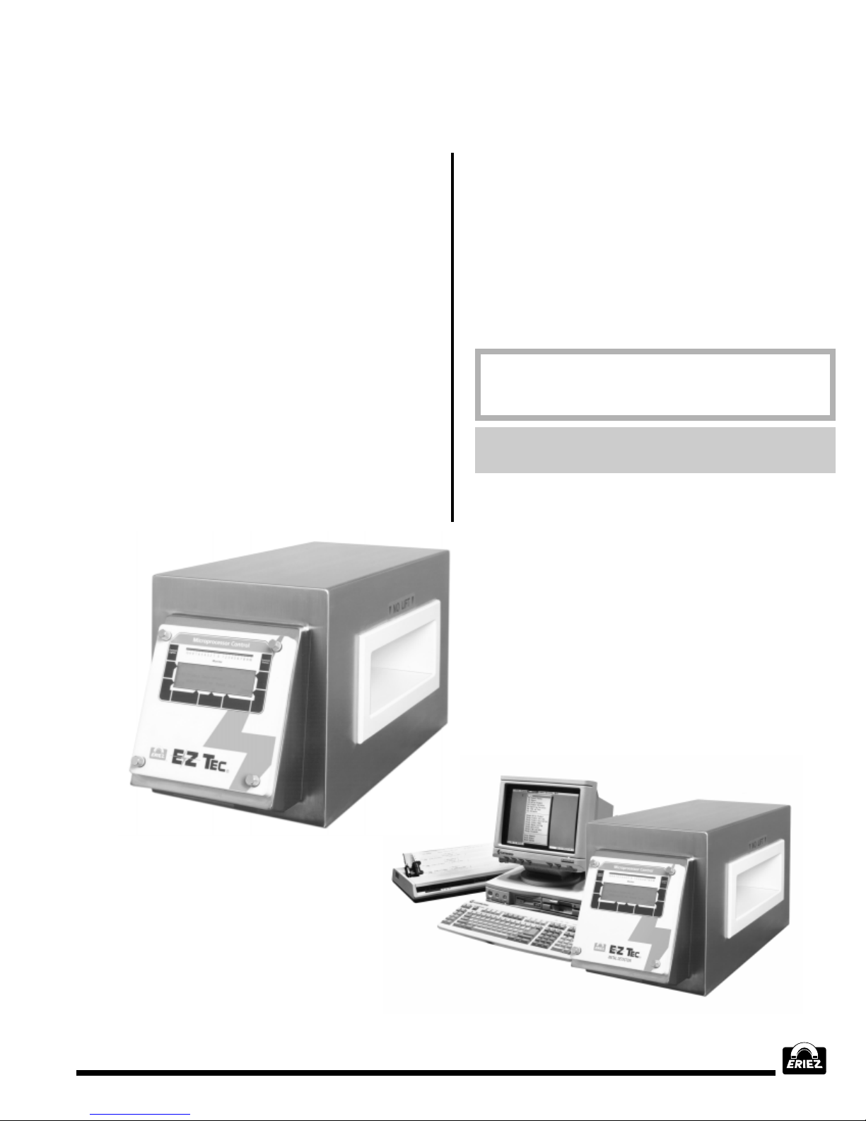
The Eriez Magnetics E-Z Tec IV and V Metal
Detectors are state of the art electronic devices
for detecting fine particles of metal in non-metallic
product streams. They are designed for accuracy ,
sensitivity, reliability and simplicity of operation.
Two variants are available: the analog version
(Figure 1) and the MicroProcessor Controlled
(MPC®) version (Figure 2). The performance,
controls, and outputs of the analog version are
ideal for most standalone industrial applications
where a simple detect-reject process is required
and the product stream has consistent
characteristics from day to day. For applications
where the detect-reject procedure may require
more frequent changes, the record keeping
requirements may be more stringent, or a
centrally controlled network of detectors is
required, Eriez provides the MPC versions of the
E-Z Tec IV and V.
This manual covers both the analog and MPC
versions of the E-Z Tec IV and V. Much of the
discussion herein is relevant to either version.
This manual provides all information necessary to
use both the E-Z Tec IV/V Metal Detector (analog
version) and the E-Z Tec IV/V MPC Metal Detector
as standalone systems. For networked or remotely
controlled installations of MPC detectors refer also
to the E-Z Tec III/IV/V MPC Communications
Manual MM-237
NOTE: Throughout this manual, information specific to the analog version of the metal detector is
set off with a gray border.
Information specific to the MPC version of the metal
detector is set off with a gray background.
Generic information—applicable to both analog and
MPC versions—is neither bordered nor shaded.
®
11

Principle of Operation
The E-Z Tec IV/V Metal Detector uses a
differential transformer to detect pieces of metal.
Three coils encircle the detection aperture. The
signal voltage in the primary coil is driven by an
oscillator. Two secondary coils, on a common axis
with the primary , are coupled into the field of the
primary coil in such a manner that the system is
in balance and the induced voltages in the two
secondary coils cancel.
A piece of metal introduced into the detection
aperture will distort the primary field and cause a
difference in induced voltages in the two secondary
coils. This voltage difference constitutes a signal
that is amplified and manipulated to extract the
amplitude and phase angle with respect to the
oscillator input signal. This information is used to
decide whether the signal represents metal or the
user’s product. If it represents the user’s product it
is ignored. If it represents metal, and if the signal
exceeds a pre-set level, the metal detector
generates a detection signal. The detection signal
is manipulated to provide various timing functions
for creating reject actions.
Figures 3 and 4 illustrate conveyor installations
of E-Z Tec analog and MPC metal detectors
respectively.
Separation of P o wer and Signal Wiring
This information is being distributed to
assemblers and electricians about the importance
of proper methods for wiring of controls. These
methods are revised and updated from time to
time as we (Eriez Magnetics) perceive necessary .
This information will cover distances from various
categories of cables and Eriez Metal Detector
wiring standards. The cable categories are:
Use separate machine entry holes for category
1, 2 and 3 cables.
When Eriez Metal Detectors are being installed
in plants using VFC drives, the following
precautions are recommended:
1. Route VFC wiring and Eriez Metal Detector
wiring in to separate metallic conduits.
1. AC power cables
2. DC distribution (thermocouple, power supplies)
3. Signal and Logic
a. Analog (low level)
b. Digital logic
Category 1 cables are to be routed along frame
members and panels. A void open space hanging.
Category 2 cables are routed as in Category 1
but separate from 1.
Category 3 cables are routed separately from
Categories 1 and 2. Category 3b cables are to
be spaced 25 cm (1") from Category 1 for each
meter of run.
®
2. Separate power sources should be used for
VFC drive and Eriez Metal Detectors.
3. The use of a Harmonic Neutralized Constant
Voltage Transformer for the Eriez Metal Detector power is recommended. Use separate
conduits for in and out wiring.
4. Twist AC common circuit run wires tegether to
minimize electromagnetic field interference.
5. Follow cable category separations as detailed
above.
12

Specifications
POWER SOURCE REQUIREMENTS
(TWO RANGES)
105 to 125 VAC 50 to 60 Hz.
Max. surges of 150 V RMS for a period
of 2 seconds.
OR
210 to 230 VAC 50 to 60 Hz.
Max. surges of 300 V RMS for a period
of 2 seconds.
Maximum demand 60 VA (Excluding
externally connected loads).
FUSES
Located in separate NEMA 4(X) enclosure
(See Figure 7).
F1 - Self resetable fuse rated at 200mA DC.
Requires no service.
F2,3,4,5,6 - Bussman GMA-1A 5X20 mm.
F7, F8 - Bussman GMC-1A 5X 20 mm.
TACHOMETER INPUT
Used to monitor variable speed conveyors.
See Appendix B.
Voltage
Logic 0 - 0.0 VDC to 0.9 VDC.
Logic 1 - 3.15 to 50 VDC .
(NPN Open Collector can also be used).
Current
Source N/A.
Sink 1 mA min.
Frequency
50 Hz max maximum.
Minimum Pulse Width
Logic 0 - 5 mSec.
Logic 1 - 5 mSec.
PROXIMITY SWITCH INPUT
Voltage
Logic 0 - 0.0 VDC to 0.9 VDC.
Logic 1 - 3.15 to 50 VDC.
(NPN Open Collector can also be used).
Current
Source N/A.
Sink 1 mA min.
Frequency
50 Hz max maximum.
Minimum Pulse Width.
Logic 0 - 5 mSec.
Logic 1 - 5 mSec.
REJECT CONFIRMATION INPUT
Voltage
Logic 0 - 0.0 VDC to 0.9 VDC.
Logic 1 - 3.15 to 50 VDC.
(NPN Open Collector can also be used).
Current
Source N/A.
Sink 1 mA min.
Frequency
50 Hz max maximum.
Minimum Pulse Width
Logic 0 - 5 mSec.
Logic 1 - 5 mSec
REJECT OUTPUTS
Direct Reject
K1 - Mechanical single pole double throw
relay rated 1A, 250 VAC or 1A, 30 VDC.
Timed Reject
K2 - Mechanical single pole double throw
relay rated 1A, 250 VAC or 1A, 30 VDC.
OPTIONAL SOLID STATE RELAYS
SSR1 - AC solid state relay rated .02 to 1.0 A,
12 to 250 VAC.
SSR2 - DC solid state relay rated .02 to 1.0 A,
5 to 60 VDC.
PRODUCT MEMORY (MPC ONLY)
The MPC is capable of storing all metal
detector adjustments and alphanumeric
descriptions for 99 separate products.
REJECT TIMERS
Direct Reject
Travel Time 0.00 sec.
Reject time 0.05 to 60 sec (these values
approximate on analog version).
Timed Reject
Travel Time 0.05 to 60 sec. (approximate
on analog version).
Reject Time 0.05 to 60 sec. (approximate
on analog version).
Shift Register Resolution 1200.
®
13

Specifications (cont.)
REJECT COUNTER (MPC ONLY)
The MPC stores a running total of the number
of times the Direct Reject output has cycled.
This normally provides a very close approximation of the total number of detections while
preventing multiple counts of the same piece
of tramp metal.
Maximum Count: 9999.
REJECT REPORTS (MPC ONLY)
The MPC stores pertinent data on the most
recent 100 rejects. Report Number, Product
Number, Time, Date, and Peak Signal Level
can be reviewed on the LCD display. The reports can be downloaded to a remote printer.
In this case, Travel Time, Timed Reject Time,
Sensitivity, Gain, and Product Description are
also included in the report. The reports can
be downloaded to a remote computer. The
computer report contains all information mentioned above plus Phase, Filter Frequency,
Detect Mode, Fault Status, Date & Time that
any one of the variables was last changed,
Direct Reject Time, Window Time, and status
of Tach Input, Direct Reject Auto Reset, T imed
Reject Auto Reset, Space Between Products,
Index Device Used?, and Reject Confirmation.
ENCLOSURE RATING
NEMA-4X/IP66.
PRODUCT VELOCITY
The metal detector can be adjusted to scan
products traveling from approximately 2 ft./min.
to 7800 ft./min. (.6 m/min. to 2400 m/min.) depending on the size and type of sensing head.
The unit is set up at the factory for optimal
performance for the customer’s application and
requires no further adjustment.
FREQUENCY
The metal detector operating frequency depends on the aperture size and the characteristics of the product to be inspected. It is adjustable but this is normally not required unless another metal detector in the area causes
interference. In this case consult the factory
for adjustment details.
BATTERY LIFE (MPC ONLY)
Minimum 1.4 years; maximum 5.0 years.
COMMUNICATION (MPC ONLY)
Printer-RS 232 (see Appendix A).
Computer-RS 232/485 (see E-Z Tec MPC
Communications Manual MM-237).
ENVIRONMENT
Ambient Temperature 0° C (32° F) to 50° C
(122° F) during operation.
Storage Temperature -10° C (14° F) to 80° C
(176° F).
Relative Humidity 0 to 95%.
NOTE: When stored at or below 0° C for
longer than six hours and then moved to a
warmer location, the temperature of the unit
should be allowed to stabilize long enough to
allow drying of moisture which may have accumulated on the electronic components (overnight is recommended). DO NOT APPLY
POWER UNTIL ELECTRONIC CIRCUITR Y IS
COMPLETELY DRY.
®
PRODUCT DESCRIPTION (MPC ONLY)
32 alphanumeric characters of description can
be stored for each of 32 separate products.
DIAGNOSTICS (MPC ONLY)
Automatic self-checking for proper operation
of the metal detector electronics at user definable intervals
Detector can show Fault condition when userscheduled calibration procedure is missed.
Receiver and transmitter independently controllable for identification and isolation of external electronic noise sources.
14

Detect Modes
E-Z T ec IV and V metal detectors can operate in either
of two detect modes. The most appropriate mode for
a given application depends largely upon
environmental conditions and upon the likely mix of
tramp metal in the product stream. The discussion
below provides guidelines on selection of the best
detect mode for your operation.
MODE 1
The metal detector control processes an analog signal
from the receiver coils of the metal detector. A typical
example of a metal signal is shown in Figure 5-A. If
the magnitude of the signal rises above a
predetermined detection threshold, the metal detector
will output a detect signal. Note that the analog signal
has a positive and a negative portion. In detect mode
1 the metal detector will detect on both portions of the
signal. The detect signal typically begins with the first
portion of the signal crossing the detection threshold
(at point “A”) and ends after the second portion of the
signal returns through the opposite detection threshold
(at point “B”). Mode 1 is usually the most sensitive
and reliable method of detection and is, therefore,
used in most applications.
MODE 2
Occasionally a metal detector is used in an
environment where significant interference is
experienced. Typical sources of interference are
lightning, static electricity , and nearby equipment with
inductive loads. These types of interference usually
cause analog signals which have only one polarity.
Figure 5-B shows typical unipolar noise signals at “D”,
“E” and “F”. Each of these signals would cause a metal
detector to false detect when operating in Mode 1
because they exceed the detection threshold level.
The metal detector can be adjusted to ignore many
of these signal types by using Mode 2 detection. Refer
again to the analog signal of Figure 5-A. Notice that
the metal signal has both a positive and negative
polarity . Mode 2 detection does not detect a unipolar
signal. It holds off detection until the second polarity
of the signal occurs. For the signal in Figure 5-A the
detection would occur at point “C”. It would last a
predetermined length of time and reset. The noise
signals in Figure 5-B would be ignored because they
are unipolar.
In general, Mode 2 detection may be somewhat
less sensitive than Mode 1 detection. Also Mode 2
detection may allow metal to pass undetected in
certain instances. Figure 5-C shows an analog
signal representing a small piece of metal followed
by a large piece of metal in the product stream.
The beginning of the signal is similar to the
beginning of the signal shown in Figure 5-A; but as
it moves toward the negative detection threshold,
the signal of the small piece of metal is absorbed
by the signal of the larger piece of metal following
it. The larger piece of metal is detected at “G”. Note
that the small piece of metal is not detected.
Extremely large pieces of metal will cause larger
sections of the product stream to be ignored
because the electronics will require more time to
recover. Therefore, the probability of missed metal
increases with the size of the tramp metal. Normally
this area is small because the tramp metal is small.
The probability is low that metal will be missed, but
the possibility exists and must be considered before
one decides to use Mode 2 detection.
If the metal detector works reliably using Mode 1
detection, Eriez recommends use of this mode.
Some applications are electrically noisy and the
number of false trips is high enough that the metal
detector cannot be used in Mode 1. In this case
one must decide whether to use Mode 2 detection
with an increased probability of missing a small
percentage of metal. The unit will ignore most noise
and still detect the overwhelming majority of the
metal. Mode 2 is much better than no protection.
However, Eriez recommends its use only when
absolutely necessary.
Every unit leaves the factory with an Individual Unit
Specifications sheet. This sheet will indicate
whether the unit is set for Mode 1 or Mode 2
detection. Most units will be set for Mode 1
detection. If the detection mode of the unit must be
changed, use switch SW2-1 on the Output Control
panel of an E-Z Tec IV or V analog metal detector
(in the Power Supply housing) or use the Detect
Mode menu option on an E-Z Tec IV or V MPC
metal detector. Detailed instructions for these
procedures are given in later sections.
®
15

Installation Caution!!
E-Z Tec IV and V metal detectors have been
manufactured to very stringent quality control
standards to ensure that they will provide years
of trouble-free service. To achieve this troublefree service, the installer must follow the
installation procedures outlined in this manual.
The details of the procedures are important, and
must be followed precisely for proper metal
detector operation.
A metal detector is by nature extremely sensitive
to very small changes in its electrical and physical
environment. Installed incorrectly, it will be very
likely to display unstable operation. It will appear
Mechanical Installation
INTRODUCTION
The metal detector contains from one to three
components which must be physically mounted to
a conveyor or suitable stand: 1) the sensing head,
2) the control (including the MPC in MPC versions)
if it is not part of the sensing head, and 3) the power
supply which may be integral with the sensinghead
and/or this control. See Figure 6.
The sensing head includes the sensing aperture
and related electronics. The control is either
attached to the sensing head or remote from it. If
the control is remote from the sensing head, its
enclosure must be mounted to a convenient
surface (free of vibration) that is easy to access
so that the metal detector can be adjusted. The
control enclosure is fitted with plastic mounting
feet that must be used to mount it.
The power supply contains all the electrical
connections to the metal detector. It is located
within a NEMA-4X enclosure (see Figure 7). This
enclosure is also fitted with plastic mounting feet
that must be used to mount it.
to be extremely sensitive to vibration and/or will
false trip (generate a false reject signal) when
the conveyor starts and stops. These and other
troubles will be prevented by proper installation
techniques.
The following installation procedures have been
collected over years of experience. Please make
use of them! Problems caused by improper
installation techniques are not covered by
warranty! A little time invested in the installation
process will pay for itself many times over by
providing a smooth trouble-free startup and
continued reliable service.
HANDLING
The metal detector must be handled with care
during installation. Follow the specific handling
guidelines attached to the detector or included in
the shipping materials. For convenience, generic
handling guidelines are included in this manual
immediately inside the front cover.
LOCATION OF SENSING HEAD
The location of the metal detector sensing head
is extremely important. The process of selecting
a location must include consideration of the needs
of the metal detector, the surrounding processing
equipment, and the operator. Product flow
including velocity and rejection of contaminants
is a major concern. Be certain to read and
understand all installation guidelines before the
final location is selected.
®
16

Mechanical Installation (cont.)
METAL FREE AREA
The metal detector monitors an electromagnetic
field to detect metal. This field is predominantly
contained within the metal detector sensing
aperture but some fringing of the field exists at
the entrance and exit openings. The fringing field
will allow the metal detector to detect metal in
the vicinity of the entrance and exit. For this
reason, metal must not be located in this area.
The required metal-free area depends on the size
of the smaller dimension of the aperture. Normally
1.5 times the smaller aperture dimension is
sufficient clearance for non-moving metal. If
space allows, a 1.75 multiplier on the smaller
aperture dimension should be used. Applications
which involve relative movement between the
sensing head and adjacent metal should use a 2.0
multiplier. (For example, stationary metal should not
be located closer than 6 to 7 inches (150 to 175mm)
from either the entrance or exit opening of a metal
detector with a 4 x 8 inch aperture. Moving metal
should not be closer than 8 inches (200mm) from
the entrance or exit of such a detector.) Please refer
to Figure 8 for details.
ELECTRICAL CURRENT LOOPS
By far the most frequent trouble experienced with
metal detector installations is false tripping
caused by electrical current loops. As was
explained in the previous section, some
electromagnetic field extends from the metal
detector aperture. The field dissipates in strength
with distance, to a point that metal contained
outside the metal-free area defined above will not
cause false detections. However, since the field
is time-varying, small electrical currents are set
up in conveyor conduction paths (i.e. metalwork)
quite some distance from the aperture. These
currents and others (e.g. ground currents from
other nearby equipment) are not harmful as long
as they are constant, but if they change, the metal
detector will false trip. Figure 9 shows a simplified
aerial view of a typical metal detector and
conveyor. The arrows located within the conveyor
framework, head pulley, tail pulley and return
idlers represent electrical currents. The bearings
supporting the pulleys and idlers represent
potential switches. As they turn, the bearings
make and break contact with their respective
races through the lubricant within. Likewise the
cross-members of the conveyor framework
represent potential switches if they are attached
to the conveyor with bolts or rivets. Through time,
connections such as these work loose or corrode
and make and break electrical connections as a
result of normal conveyor vibrations. Potential
switches of both these types must be eliminated.
INSULATING THE CONVEY OR
SHAFTS
In the case of pulleys and idlers there is no way
to make the electrical path constant enough to
prevent changes in the currents. These currents
must be eliminated by introducing an insulating
medium within the conduction path. Figure 10
shows two common methods.
The method shown in Figure 10-A is
accomplished by machining the end of the shaft
which rides in the bearing to a small diameter
and inserting an Ultra-High Molecular Weight
(UHMW) plastic sleeve over it. The outside
diameter of the sleeve is the same as the inside
diameter of the bearing. This sleeve breaks the
electrical connection between the bearing and the
shaft, thus permanently preventing current flow.
WARNING: Do not cut through the sleeve when
tightening the bearing set screw.
Figure 10-B shows a method of insulating the
complete bearing block from the conveyor frame.
This requires drilling the bolt holes through the
bearing block to a larger diameter to accept an
insulating shoulder washer. The shoulder washer
wall thickness should be at least 1/32" (1 mm).
Alternatively the shoulder washer can be
replaced with a plastic washer and a length of
plastic pipe or hose. Insulating the bolt with
tape is not recommended. The bearing block
is insulated from the conveyor frame with a
UHMW insulator extending entirely across the
base of the block as shown.
®
17

Mechanical Installation (cont.)
Both insulating methods are reliable. However, it
takes only a small metal shaving or burr to cut
through and short-circuit the insulators. For this
reason the insulation should be tested with an
ohmmeter after the pulley or idler is installed on
the conveyor frame. Obviously insulating either
end of the shaft will prevent current loops.
However, leaving one end uninsulated will prevent
testing with an ohmmeter. For this reason
insulating both ends is recommended.
Sometimes when the humidity is low, static
electricity will form on the conveyor belt. A charge
can build up on pulleys or idlers which are
insulated on both ends. This should be prevented
because static discharge may cause the metal
detector to false trip. After the integrity of the
insulators is checked with an ohmmeter, one end
of each shaft should be electrically reconnected
to the conveyor frame. In the case of the sleeve
insulating method the set screw of one of the
bearings should be used. This may require drilling
a small hole down through the sleeve and
inserting a sharp pointed set screw. In the case
of the bearing block insulating technique simply
remove one of the shoulder washers on one end
of the shaft. Note that in both methods if at any
future time the integrity of the insulators is in doubt
they can be checked again easily.
NOTE: If the conveyor belt drive pulley is driven
with a metal chain, do not defeat the insulators
on either end of the shaft. The metal drive chain
will bleed off any static charge which may accumulate on the pulley.
PERMANENT LOOPS
Permanent conduction paths (such as cross
members) associated with the conveyor frame must
be welded securely . In this way currents flowing in
the loops will remain constant. Bolted construction
is not permissible. Any conduction path which is to
remain removable or is simply not weldable must
be insulated from the conveyor frame.
Figure 11 shows the modified conveyor frame.
Note the potential switches no longer exist and
the only currents in the conveyor frame are
running through welded, permanent connections.
They will be consistent and therefore will not
cause false detections.
IMPORTANT:
It is risky to accept an installation with bolted
conveyor construction, even though tests may
show that no metal detector false trips occur when
bolted structural members are deliberately
shaken or twisted. No matter how good the bolted
connections are initially , there is a high likelihood
that such connections will eventually degrade or
loosen, creating an unstable electrical pathway
that interferes with metal detector operation and
that may be extremely difficult to locate. Use only
welded or insulated construction techniques.
MOUNTING BASE
The base to which the metal detector sensing
head is mounted must be strong, rigid, and as
free as possible from vibration. Although the metal
detector can be set up to be relatively insensitive
to vibration, better sensitivity to metal can often
be obtained by preventing vibration from reaching
the detector head.
Four insulating mounting feet are supplied with
the metal detector. They must be used (refer to
Figure 12). All four must sit flat on the mounting
base. Never draw the feet down to the stand by
tightening the mounting bolts. This will put uneven
stresses on the sensing head and possibly cause
instability. If for any reason the feet do not all sit
flat on the mounting base, shim with appropriate
washers until all four mounting feet are carrying
the same load.
Nothing except the insulating feet and electrical
connections may contact the sensing head.
Conduit attached to the metal detector shell
should utilize plastic fittings (refer to Electrical
Installation).
®
18

Mechanical Installation (cont.)
BELT SPLICES
The metal detector sensing head cannot be
disassembled to be fitted around the conveyor
belt. For this reason the conveyor must be
designed to return the belt through the aperture,
or the belt must be cut and spliced back together.
Splicing the belt with lacing or clamps is not
recommended because foreign materials tend to
collect at the joint, and these eventually cause
false detections.
Vulcanized splices are recommended for best
reliability. Refer to Figure 13 for typical splice
types. If the belt is single-ply, the Finger Splice
configuration should be used. If the belt is multiply, a combination of Step/Finger Splice
configuration is recommended.
Cold bonding is a popular on-site practice. In this
case the splice is usually a Beveled or Step-Lap
type. Adhesives are available which are food or
non-food grade. In either case the splices should
be diagonal rather than straight across the belt.
The cold bond splice is adequate for many
applications as long as the splice is diagonal but
the Vulcanized Finger splice is preferred.
NOTE: During all splicing it is absolutely necessary to ensure that no foreign material (especially
metal) is trapped within the splice. If this happens,
the metal detector will trip every time the splice
passes through the aperture. Since the metal is
trapped inside the splice it cannot normally be located and removed without ruining the belt.
CONVEYOR SLIDER BED
The conveyor belt must be supported as it travels
through the metal detector. This task is performed
by a slider bed, which must be capable of holding
the belt off the aperture liner even when fully loaded.
The slider bed must not contact the metal detector
aperture liner. It should be supported by the
conveyor frame. The slider bed should be made of
static-resistant non-metallic material. Wood and
phenolic are good choices. Plastic should normally
not be used because it tends to generate static
electricity as the conveyor belt slides across it.
PRODUCT POSITION
The product should always be guided through the
center of the aperture, both vertically and
horizontally. This is true whether the product
travels through the metal detector on a conveyor
or flows through a pipe as in a vertical application.
If multiple size products will be inspected by the
same metal detector, design the system to center
the largest product in the aperture.
REJECT PROXIMITY SWITCH
The proximity switch is used to indicate when a
package aligns with a reject device. For example,
a product in a box may need to align with a reject
device, such as a pusher arm, to be rejected
reliably. The proximity switch indicates when the
alignment is achieved. Normally the proximity
switch is positioned just after the reject device
so that it is triggered as the product aligns with
the reject device. If it is difficult to install a switch
in that location, it can be installed upstream from
the reject device. In this case the proximity switch
must contain a delay timer capable of delaying
the output until the product aligns with the reject
device. Be certain not to infringe on metal detector
metal free areas when choosing the location of
the proximity switch.
®
19

Electrical Installation
INTRODUCTION
All electrical connections are intended to be made
within the NEMA-4X power supply enclosure.
Figure 14 shows the enclosure and the electrical
connections to the power supply circuit board.
There are no user serviceable electronics or
electrical connections within the control
enclosure. Never attempt to remove the detector
control from the control enclosure.
CHOICE OF INPUT PO WER SOURCE
The metal detector is equipped with filtering
devices to help eliminate incoming electrical
noise. Noise is usually created by inductive loads
sharing the same power circuit. Even with the
filters there is a limit to what the metal detector
can withstand without false tripping.
The best insurance against electrical noise is to
run a separate circuit from the main power bus.
This circuit should be free of all loads except the
metal detector. The power line should be run in its
own metal conduit. The conduit must be electrically
insulated from the conveyor. This includes any
supporting structure for the metal detector. If this is
impossible or impractical, reliable operation can
often be obtained by powering the metal detector
from a “clean” lighting circuit. This circuit must be
free of inductive loads such as motors, solenoids,
motor starters, variable frequency drives, etc.
If the metal detector must be powered by a less
favorable source, false tripping caused by line noise
can usually be eliminated through the use of a
harmonic neutralized constant voltage transformer.
POWER SUPPLY
Refer to Figure 14 for wiring to the power supply.
The metal detector may be powered at either of
two voltage ranges described in the specifications
section of this manual. Be certain the input power
voltage selection switch is in the proper position to
accept the power supply. The voltage selection
switch is shown in Figure 14 and is labeled SW2
on the circuit board.
CAUTION:
Be careful to distinguish between the input
voltage selection switch and the power (off/on)
switch. Both are located in the lower left corner
of the power supply circuit board. THE VOL TAGE
SELECTION SWITCH IS RED, AND IS LABELED
WITH THE AVAILABLE VOLTAGES, 115V AND
230V . THE POWER SUPPLY SWITCH IS BLACK,
AND IS LABELED WITH 0 AND 1, TO INDICATE
OFF AND ON, RESPECTIVELY. INADVERTENT
USE OF THE IMPROPER SWITCH COULD
LEAD TO CIRCUIT DAMAGE AND/OR
PERSONAL INJURY. See Figure 14 for the
location of these two switches.
The power source attaches to terminals L1 and
L2. If operating in the 115 VAC range, L1 is the
active or high side of the line and L2 is the neutral.
If operating in the 230 V AC range, connect either
supply line to L1 and the other to L2.
Note that L1 and L2 are connected through circuit
board traces to other terminals on the circuit
board as labeled. They are intended to be
conveniently available to the user to power
various ancillary equipment. They are not fused
on the circuit board. It is the user’s obligation to
be certain L1 and L2 lines are adequately fused
external to the metal detector, preferably at the
power source.
The power source must contain a reliable ground.
It must be connected to the “GND” terminal.
NOTE: The metal detector may be grounded at only
one point, through the power supply ground wire.
No other ground connections are permitted. This
includes mounting hardware and conduit.
The metal detector electronics are protected by
1A fuses (GMC-1A). The fuses are located
between the POWER SUPPLY L1 and L2
terminals and the metal detector electronics. Note
there are no fuses between the POWER SUPPL Y
L1 and L2 terminals and the other L1 and L2
terminals on the circuit board.
®
20

Electrical Installation (cont.)
RELAYS
The E-Z Tec IV and V provide three standard and
two optional relays as follows:
DIRECT RELAY
The Direct Relay is a mechanical SPDT (single
pole double throw) relay. The relay contacts are
labeled on the circuit board showing the
respective terminal connections. The relay is
shown energized which is its normal non-reject
state (this provides fail-safe relay operation).
When Direct Reject occurs, the relay changes to
the state opposite that shown (the relay is deenergized which causes the left contacts to close
and the right contacts to open). After the reject
clears, the relay is again energized switching it
back to its original position.
TIMED RELAY
The Timed Relay is a mechanical SPDT (single
pole double throw) relay. The relay contacts are
labeled on the circuit board showing the
respective terminal connections. The relay is
shown energized which is its normal non-reject
state (this provides fail-safe relay operation).
When Timed Reject occurs, the relay changes to
the state opposite that shown (the relay is deenergized which causes the left contacts to close
and the right contacts to open). After the reject
clears, the relay is again energized switching it
back to its original position.
FAULT RELAY
The Fault Relay is a mechanical SPDT (single
pole double throw) relay. The relay contacts are
labeled on the circuit board showing the
respective terminal connections. The relay is
shown energized which is its normal non-fault
state (this provides fail-safe relay operation). If a
fault condition occurs, the relay changes to the
state opposite that shown (the relay is deenergized which causes the left contacts to close
and the right contacts to open). After the fault
clears, the relay is again energized switching it
back to its original position.
AC SSR
The AC SSR is a solid state relay suitable for
switching AC loads only. It functions in parallel
with the Timed Relay described above. The relay
contacts are labeled on the circuit board showing
the respective terminal connections. The polarity
(e.g. normally open or normally closed) is
adjustable using SW1. If the switch is in the right
position, the relay is normally closed. When Timed
Reject occurs, the relay changes state (the relay
is de-energized which causes the relay to open).
After the reject clears, the relay is again energized
switching it back to its original position. If SW1 is
in the left position, the relay operates opposite in
polarity to that just described.
NOTE: This relay is optional. This relay is only
installed in units where the relay was requested
by the customer at the time of manufacture.
DC SSR
The DC SSR is a solid state relay suitable for
switching DC loads only. It functions in parallel
with the Timed Relay described above. The relay
contacts are labeled on the circuit board showing
the respective terminal connections. Note the left
terminal is positive and the right terminal is
negative. The polarity (e.g. normally open or
normally closed) is adjustable using SW1. If the
switch is in the right position, the relay is normally
closed. When Timed Reject occurs, the relay
changes state (the relay is de-energized which
causes the relay to open). After the reject clears,
the relay is again energized switching it back to
its original position. If SW1 is in the left position,
the relay operates opposite in polarity to that just
described.
NOTE: This relay is optional. This relay is only
installed in units where the relay was requested
by the customer at the time of manufacture.
®
21

Electrical Installation (cont.)
RELAY NOTES
As shipped, none of the relays source power. If
switched AC power is needed it must be supplied to
the appropriate relay through a jumper, such as from
one of the L1 or L2 terminals or from an external
source. If switched DC power is needed it must be
supplied from a remote source or from the +5 TACH
terminal (5 volts DC, 100mA max.). All relays are
protected by a 1A fuse (GMA-1A).
Solid state relays cannot be tested with most
ohmmeters. T est the solid state relays by applying an
appropriate power source and load.
INPUTS
The metal detector will accept inputs from external
devices of various types. The terminals for these inputs
are located at the lower edge of the Power Supply
PCB, and are described functionally below.
TACHOMETER INPUT (TACH)
Applications having variable speed product flow and
needing automatic reject timing use this input. A
tachometer is used to allow the metal detector control
to monitor product speed and reject according to the
distance the product has traveled rather than elapsed
time since detection. (Refer to Appendix B for details.)
The electrical specifications are as follows:
Voltage
Logic 0 - 0.0 VDC to 0.9 VDC
Logic 1 - 3.15 to 50 VDC
(NPN Open Collector can also be used)
Current
Source N/A
Sink 1 mA min
Frequency
50 Hz max
Minimum Pulse Width
Logic 0 - 5 mSec
Logic 1 - 5 mSec
PROXIMITY SWITCH (PROX SW)
Sometimes the metal detector is used to scan and
automatically reject packages. A proximity switch
is used to sense the location of the package so it
can be rejected reliably. The device can be a
mechanical switch, photo-eye, or any other device
which is capable of precisely locating the package.
The electrical specifications are as follows:
Voltage
Logic 0 - 0.0 VDC to 0.9 VDC
Logic 1 - 3.15 to 50 VDC
(NPN Open Collector can also be used)
Current
Source N/A
Sink 1 mA min
Frequency
50 Hz max maximum
Minimum Pulse Width
Logic 0 - 5 mSec
Logic 1 - 5 mSec
Note the right terminal of this input is ground. Since
the metal detector is to be grounded only by the
input power supply ground, this terminal must not
be grounded by the proximity device.
REJECT CONFIRMATION (REJ CON)
The reject confirmation input is used to monitor the
function of the reject device. It is usually a limit
switch attached to the reject device which indicates
it is functioning. For example, the device may be a
switch attached to a pusher bar used to reject a
box off a conveyor . The switch is positioned in such
a way that it closes as the pusher bar reaches its
maximum extension. The electrical specifications
are as follows:
Voltage
Logic 0 - 0.0 VDC to 0.9 VDC
Logic 1 - 3.15 to 50 VDC
(NPN Open Collector can also be used)
Current
Source N/A
Sink 1 mA min
Frequency
50 Hz max maximum
Minimum Pulse Width
Logic 0 - 5 mSec
Logic 1 - 5 mSec
Note the right terminal of this input is ground. Since
the metal detector is to be grounded only by the
input power supply ground, this terminal must not
be grounded by the limit switch.
®
22

Electrical Installation (cont.)
REJECT RESET (REJ RESET)
The metal detector has two reject outputs, Direct
and Timed. Either or both can be set to reset
manually following a reject. The Reject Reset input
can be used to reset the rejects. Normally a
momentary close push-button switch is used. The
electrical specifications are as follows:
Voltage
5 VDC
Current
20 mA
Note the right terminal of this input is ground. Since
the metal detector is to be grounded only by the
input power supply ground, this terminal must not
be grounded by the switch.
HOST COMPUTER PORT (MPC ONLY)
The MPC version is capable of communicating with
one or more host computers (typically PCs) through
an RS232 or RS485 link. Please refer to the E-Z
Tec MPC Communication Manual MM-237 for
further information on the use of this port.
PRINTER PORT (MPC ONLY)
The MPC can drive a remote printer through an
RS232 link to print reject reports. This subject is
covered in detail in Appendix A, Printer Operation.
support structure. Metallic conduit fittings must
not be used to attach conduit to the metal detector
housing. Always use a plastic fitting for this
purpose. Conduit for "other" equipment must not
be run along the metal detector conveyor.
Although the conduit serves as shielding, possible
interference could occure.
NOTE: The power on/off switch located inside the
power supply enclosure is intended to be a service
convenience only. It is recommended that the unit
remain on continuously . This will provide best metal
detector performance and enhance the longevity
of the electronic components.
CAUTION:
Be careful to distinguish between the input voltage
selection switch and the power (off/on) switch. Both
are located in the lower left corner of the power
supply circuit board. THE VOLTAGE SELECTION
SWITCH IS RED, AND IS LABELED WITH THE
AVAILABLE VOLTAGES, 115V AND 230V. THE
POWER SUPPLY SWITCH IS BLACK, AND IS
LABELED WITH 0 AND 1, TO INDICA TE OFF AND
ON, RESPECTIVELY. INADVERTENT USE OF
THE IMPROPER SWITCH COULD LEAD TO
CIRCUIT DAMAGE AND/OR PERSONAL INJURY.
See Figure 14 for the location of these two switches.
CONDUIT
It is always wise to run wiring to and from the metal
detector through metal conduit. High voltage wiring
for the power supply and reject devices should not
be installed in the same conduit as low power sensor
wiring (such as wiring for the tachometer and reset
switch). Always keep all metal detector wiring
separate from cables carrying heavy or switched
loads. This is especially true with variable speed
motor control wiring. If these guidelines are followed,
interference from electrical noise will be greatly
decreased.
The use of metal conduit will provide necessary
shielding for the wires within; however, metal conduit
also represents a potential ground path. Metallic
conduit or airlines must be electrically insulated
from the associated components of the metal
detector, such as conveyor, stand or any other
INITIAL TEST (ANALOG UNIT)
a. After all electrical connections are com-
pleted and checked, turn the power switch,
SW4, on. The two center green LED’s in
the bar graph of the metal detector control
panel (Figure 15) should light.
b. Pass a large piece of metal through the
metal detector aperture. The LED bar graph
should respond with positive and negative
excursions of the red LED’s.
c. If the above does not occur, check all in-
stallation instructions, fuses, and input
power. If the fault cannot be located, contact Eriez Magnetics for assistance.
d. Close and latch the power supply enclo-
sure door.
®
23

Electrical Installation (cont.)
INITIAL TEST (MPC UNIT)
a. After all electrical connections are com-
pleted and checked, turn the power switch,
SW3, on. The two center green LED’s in
the bar graph of the MPC control panel (refer to Figure 18) should light. The LCD alphanumeric display should respond with
“ERIEZ MAGNETICS,” address, telephone,
and fax numbers. After approximately 10
seconds, the MONITOR display should appear on the LCD screen showing time, date,
SENSITIVITY ##, and PHASE ##.
b. Pass a large piece of metal through the
metal detector aperture. The LED bar graph
should respond with positive and negative
excursions of the LED’s. The LCD display
top line should register “REJECT” in the top
left corner and “REJECT” in the top right
corner.
c. If any of the above do not occur, check all
installation instructions, fuses and input
power. If the fault cannot be located, con-
tact Eriez Magnetics for assistance.
d. Close and latch the power supply enclo-
sure door.
®
24

Analog Controls and Displays
ANALOG CONTROL PANEL
Figure 15 shows the location of the various front
panel controls and indicators on the E-Z Tec
Version IV and V analog unit. These controls and
indicators are primarily concerned with the
detection performance of the unit.
LARGE RECTANGULAR
STATUS LED’S
The two large rectangular LED’s (Light Emitting
Diodes) in the center of the E-Z Tec control panel
indicate the metal detector status as follows:
DETECT (RED)
Used to indicate that metal has been detected. It
illuminates as metal is detected and extinguishes
soon after detection terminates.
FAULT (YELLOW)
Used to indicate that the coils are unbalanced or
that the reject confirmation failed.
MONITOR DISPLAY
This is an LED bar graph display . The center two
segments are non-extinguishing green LED’s.
They indicate power-on. Red LED excursions to
right and left indicate relative signal intensity. All
red LED’s are off when no signal is present.
SENSITIVITY CONTROL
The sensitivity control is a 100 position switch. A
setting of 99 provides maximum sensitivity. The
adjustment is variable in 01 increments down to
00, at which point the metal detector sensitivity
is very low, and the unit will detect only extremely
large pieces of metal.
PHASE CONTROL
This control is a 1000 position switch. It is used
to make the unit more or less responsive to
various types of materials passing through the
aperture. This control can be used to provide
maximum response to a particular type of metal
or (more often) minimum response to a particular
product. The latter procedure is termed “phasing
out the product effect.”
ANALOG OUTPUT CONTROLS
Figure 16 illustrates the output control panel of
the E-Z Tec Version IV and V analog metal
detector. This panel is located in the power supply
housing. The controls and switches on this panel
are primarily concerned with the rejection
performance of the unit.
TRAVEL TIME
Often contaminated product is automatically
eliminated from the product flow by a suitable
reject device. The reject signal from the metal
detector must be delayed until the contaminated
product travels to the reject device. This delay is
called Travel Time. It is adjustable using the
Travel T ime control knob and the jumper JP2. The
control knob has a range of 0 to 10 units, with
the value of each unit depending on the setting
of JP2. Note that this control is not present in the
MPC metal detector because the relevant function
is controlled by user input at the front panel (or
through the computer interface).
REJECT TIME
The time required for a reject device to perform
its function varies widely depending on the
particular application. The reject time of the timed
relay is controlled by the STANDARD reject
adjustment or the INDEXED reject time
adjustment depending on the setting of SW2-2.
Note that these controls are not present in the
MPC metal detector because the relevant
functions are controlled by user input at the front
panel (or through the computer interface).
STANDARD REJECT
Time The STANDARD REJECT TIME adjustment
determines the amount of time that the TIMED
RELA Y will remain in the detect state when SW22 is set for the standard reject setting. This interval
is adjustable from 0.12 seconds to 9.5 seconds.
INDEXED REJECT TIME
When the INDEXED reject is selected with SW22 the amount of time that the TIMED RELAY will
remain in the detect state is set with the INDEXED
reject adjust. This interval can be adjusted from
0.12 seconds to 9.0 seconds.
®
25

Analog Controls and Displays (cont.)
PROGRAMMING SWITCHES
These switches are located in the power supply
housing of the analog metal detector. They are
labeled SW1 and SW2. The functions controlled
by these switches are detailed in the section “Circuit
Board Switch Programming.” Note that these
switches are not present in the MPC metal detector
because the relevant functions are controlled by
user input at the front panel (or through the
computer interface).
FAULT INDICATOR
There are two conditions that can cause the FAUL T
LED on the analog control panel to illuminate. These
two conditions are indicated on the output control
panel (in the power supply housing) as BALANCE
and REJECT and are explained below.
BALANCE LED
When the BALANCE LED is illuminated it
indicates that the coils in the search head are
out of balance and the sensitivity of the metal
detector may be in question. The coils must be
out of balance for approximately two minutes
before this is considered a fault condition and the
fault relay actuates. The BALANCE LED is reset
as soon as the coils are balanced.
REJECT LED
The REJECT LED indicates that there was not a
confirmation signal from the reject device when it
was to reject metal within the last two minutes. The
REJECT LED only indicates a fault condition when
SW1-1 is set to enable the reject confirmation.
illuminates as soon as there is no metal being
detected and direct relay output has returned to
its normal state.
TIMED
The TIMED LED is off when the timed relay output
is in a reject state.
ACSSR
The ACSSR LED is off when the AC solid state
relays output is off. The AC solid state relay
operates at the same time the TIMED RELAY
operates. The output of the AC solid state relay
may be on or off during reject depending on the
setting of SW2-4.
DCSSR
The DCSSR LED is off when the DC solid state
relays output is off. The DC solid state relay
operates at the same time the TIMED RELAY
operates. The output of the AC solid state relay
may be on or off during reject depending on the
setting of SW2-4.
FAULT
The FAULT LED indicates the status of the
FAULT RELAY output. The FAULT LED is
normally illuminated and turns off when a fault
condition occurs.
WINDOW LED
The Window LED on the analog output control
panel is illuminated to indicate the period of time
during which a reject can occur when switch SW22 is set to enable INDEXED reject.
RELAY STATUS LEDS
The five RELAY STATUS LED’s on the output
control panel in the power supply housing indicate
the state of the five relay outputs. The two solid
state relays are optional, but the status LED’s will
always indicate what their status is even if the solid
state relays are not installed.
DIRECT
The DIRECT LED is illuminated when the metal
detector is operating properly and no metal is
detected. As soon as the metal is detected the
DIRECT LED turns off to indicate that the direct
relay output has changed states. The DIRECT LED
®
INDEX IN LED
When a proximity sensor is used to locate the
package to be rejected the INDEX IN LED
illuminates when a package is detected. If a
proximity sensor is not used this LED does not
illuminate.
CONFIRM LED
When reject confirmation is used to verify the
operation of the reject device, the CONFIRM LED
illuminates to indicate a signal from the reject
confirmation device was received. If reject
confirmation is not used the CONFIRM LED does
not illuminate.
26

Analog Controls and Displays (cont.)
CLOCK LED
The CLOCK LED is used to show the rate at which
the timer for the timed relay is operating. When the
internal clock is selected with SW2-3 the CLOCK
LED flashes at the rate at which the internal clock
is running. When SW2-2 is set to select the
tachometer input for the clock, the CLOCK LED
flashes at the rate at which the pulses from the
tachometer are occurring.
DETECT LED
The DETECT LED illuminates when the sensing
head sends a signal indicating metal has been
detected.
ANALOG CIRCUIT BOARD
SWITCH PROGRAMMING
Figure 17 shows the various switch locations on
the analog unit output control panel, PSOPT-1.
The user programmable switches are listed on
Page 23 along with a brief explanation of their
function. The discussion below provides a source
for quick reference.
SW1-1
When a reject confirmation device is connected to
the metal detector, SW1-1 must be set to the UP
position for the metal detector to process the signal.
If a reject confirmation device is not connected to
the metal detector, SW1-1 must be set to the DN
position or a fault condition will occur.
SW1-2
When this switch is set to the UP position the output
of the TIMED RELAY will not reset after a reject
until a signal is received at the REJ RESET input.
When SW1-2 is set to the DN position the TIMED
RELA Y output will reset automatically. The time for
the relay to reset is determined by the ST ANDARD
REJECT TIME when SW2-2 is in the UP position
or by the INDEXED REJECT TIME when SW2-2 in
the DN position.
SW1-3 THROUGH SW1-8
These switches set the length of the shift register.
Refer to the SWITCH CHART for switch settings
and shift register length. Refer to Appendix B for a
discussion of the Shift Register function.
SW1-9
When this switch is set to the UP position the
DIRECT RELAY will not reset after a reject until a
signal is received at the REJ RESET input. When
SW1-9 is set to the DN position the DIRECT RELA Y
output will automatically reset after a reject.
SW2-1
This switch selects MODE 1 or MODE 2 detection.
Refer to the DETECT MODE DESCRIPTION
section of this manual for an explanation of MODE
1 and MODE 2. MODE 1 is also referred to as
normal detection and is selected when SW2-1 is in
the UP position. MODE 2 is also referred to as
narrow zone detection and is selected when switch
SW2-1 is in the DN position.
SW2-2
This switch selects between INDEXED REJECT
and STANDARD REJECT for the TIMED RELAY
output. When SW2-2 is in the UP position,
INDEXED REJECT is selected and the reject time
is adjusted with the INDEXED REJECT TIME.
When SW2-2 is in the DN position, STANDARD
REJECT is selected and the reject time is adjusted
with the STANDARD REJECT TIME.
SW2-3
This switch is used to select an internal clock or a
tachometer input for the travel time on the TIMED
RELA Y output. When the switch is in the UP position,
the source of the clock is from the tachometer input.
When the switch is in the DN position the source of
the clock is from an internal clock.
SW2-4
This switch is used to determine whether the
output of the solid state relays is to be ON
during reject or OFF during reject. When the
switch is in the UP position the output of the
solid state relays turns OFF when a reject
occurs. When the switch is in the DN position
the output of the solid state relays turns ON
when a reject occurs.
®
27

Analog Controls and Displays (cont.)
JP1
This jumper is to set up the metal detector
when a proximity sensor is used. If there is
always a space between packages, then JP1
is OFF (open). When a space between
packages cannot be guaranteed, then JP1 is
ON (shorted).
JP2
This jumper is used to set the range of
adjustment the TRAVEL TIME has. When JP2
is ON (shorted) the TRAVEL TIME has an
Switch Chart A - Output Board PSOPT-1
SWITCHES AND JUMPERS
SWITCH POSITION/SETTING POSITION/SETTING
SW1-1 UP Reject confirmation is OFF DOWN Reject confirmation is ON
SW1-2 UP Timed output is manually reset DOWN Timed output is automatically reset
adjustment range of 0.30 seconds to 50
seconds. When JP2 is OFF (open) the TRA VEL
TIME adjustment has a range of 0.05 seconds
to 10 seconds. JP3 This jumper is used to
inhibit the reject during power up. With JP3 ON
(shorted the DIRECT RELAY and the TIMED
RELAY outputs will not reject until the power
to the metal detector has been on for 10
seconds. When JP3 is OFF (open) the DIRECT
RELAY and TIMED RELAY will be active as
soon as power is turned on.
SW1-3 Sets the length of the Shift Register. See Switch Chart B.
SW1-4 Sets the length of the Shift Register. See Switch Chart B.
SW1-5 Sets the length of the Shift Register. See Switch Chart B.
SW1-6 Sets the length of the Shift Register. See Switch Chart B.
SW1-7 Sets the length of the Shift Register. See Switch Chart B.
SW1-8 Sets the length of the Shift Register. See Switch Chart B.
SW1-9 UP Direct output is manually reset DOWN Direct output is automatically reset
SW2-1 UP MODE 1 detection DOWN MODE 2 detection
SW2-2 UP Indexed reject DOWN Standard reject
SW2-3 UP Tachometer input DOWN Internal clock
SW2-4 UP SSR output is normally closed DOWN SSR output is normally open
JP1 ON Not always space between packages OFF Always space between packages
JP2 ON Travel time (0.30sec - 50sec, ± 10sec) OFF Travel time (0.05sec -10sec, ± 2sec)
JP3 ON 10sec reject inhibit at power on OFF Reject enabled at power on
®
28

Controls and Displays (cont.)
Switch Chart B
Output Board PSOPT-1
SWITCHES SW1-3 THROUGH SW1-8 U = UP D = DOWN
Shift Shift
Register
Length 3 4 5678Length 345678
0 UU UUUU 32 DUUUUU
1 UU UUUD 33 DUUUUD
2 UU UUDU 34 DUUUDU
3 UU UUDD 35 DUUUDD
4 UU UDUU 36 DUUDUU
5 UU UDUD 37 DUUDUD
6 UU UDDU 38 DUUDDU
7 UU UDDD 39 DUUDDD
8 UU DUUU 40 DUDUUU
9 UU DUUD 41 DUDUUD
10UU DUDU 42 DUDUDU
11UU DUDD 43 DUDUDD
12UU DDUU 44 DUDDUU
13UU DDUD 45 DUDDUD
14UU DDDU 46 DUDDDU
15UU DDDD 47 DUDDDD
16UD UUUU 48 DDUUUU
17UD UUUD 49 DDUUUD
18UD UUDU 50 DDUUDU
19UD UUDD 51 DDUUDD
20UD UDUU 52 DDUDUU
21UD UDUD 53 DDUDUD
22UD UDDU 54 DDUDDU
23UD UDDD 55 DDUDDD
24UD DUUU 56 DDDUUU
25UD DUUD 57 DDDUUD
26UD DUDU 58 DDDUDU
27UD DUDD 59 DDDUDD
28UD DDUU 60 DDDDUU
29UD DDUD 61 DDDDUD
30UD DDDU 62 DDDDDU
31UD DDDD 63 DDDDDD
Switch SW1-
Register
Switch SW1-
®
29

MPC Controls and Displays
MPC CONTROL PANEL
Figure 18 illustrates the E-Z Tec IV and V MPC
control panel. The panel consists of a 22 segment
LED bar graph, an 8 line x 40 character Liquid
Crystal Display (LCD), and nine push-button switch
keys. The operator controls the MPC through the
interaction of these components.
LED BAR GRAPH
The bar graph monitors all signals entering the metal
detector. Its major role is to aid the operator in
adjusting for product effect and vibration. More
information on this function is presented in the
“Metal Detector Adjustment” section.
SWITCH KEYS
The operator commands the MPC to perform all
functions with the switch keys. T wo of the keys are
labeled Contrast Lighten and Contrast Darken. Their
only task is to adjust the contrast of the LCD to suit
the operator. The other keys are known as soft keys
since their function is controlled by the MPC
software program. Each soft key has an arrow
pointing to a section of the display. The current
function of the key is displayed there.
LCD
The LCD is the medium through which the MPC
displays information. This includes all setup
parameters, metal detection status, and reports. It
is equipped with a backlight to illuminate the display
in dark environments. The backlight turns on
following any key press and remains on until ten
minutes has elapsed with no key activity.
MPC SOFTWARE
The software is a computer program stored in the
MPC memory. It tells the microprocessor what to
do and how to communicate with the operator. It
has been designed to be user friendly. Although a
complete discussion of adjustment procedures is
provided below, memorization of these should not
be necessary because the prompts and help files
lead the way through the adjustment routines. A
good general understanding of the procedures and
parameters are all that should be required to adjust
the MPC.
FLOWCHAR T
Figure 19 is a flowchart representing the structure of
the portion of the MPC software which communicates
with the operator. It is a graphical representation of
the flow of the program showing how to move to
different sub-menus. Consider it a road map showing
how to get from one sub-menu to another.
Each block of the flowchart represents a sub-menu.
The arrows between the blocks represent the
possible links between sub-menus. Each arrow has
a short description indicating how to direct the
program along that link.
Example:
a. Refer to the “Product Setup” sub-menu in
Fig. 19.
b. This menu is reached via the “Main Menu”
by entering the Product Setup command.
c. The Exit command returns the program to
“Main Menu.”
Each sub-menu fits on one full screen of the LCD display .
Since the screen is quite large, each menu provides a
variety of information. One advantage of the large screen
is to provide directions to guide the operator through
adjustments. In addition, multiple parameters are
displayed on each menu, so that the number of links in
the flowchart is substantially reduced.
GENERAL MPC OPERATION
At first glance the MPC menu flowchart may look
somewhat complex. Actually it is extremely simple.
The following sections introduce the four major
portions of the software flowchart and the General
Operation Information. Further information on all of
these sub-menus is available in the Detailed Menu
Description and Adjustment section of this manual.
MONITOR
Under normal operating conditions the MPC “resides”
at the MONITOR MENU. The operator can change
products and obtain information necessary to consult
the factory for assistance without going through the
MAIN MENU. This is provided as a convenience to
the operator since changing the product under
inspection is the only adjustment normally
necessary after the initial unit setup.
®
30
 Loading...