

Eriez 58B, 62B, 70B, 65B, 75B Installation, Operation And Maintenance Instructions
Installation, Operation
and Maintenance
Instructions
VM-3364M
VIBRATORY
FEEDERS
MODELS 58B, 62B,
65B, 70B & 75B
ERIEZ WORLD HEADQUARTERS: 2200 ASBURY ROAD, ERIE, PA 16506–1402 U.S.A.
WORLD AUTHORITY IN SEPARATION TECHNOLOGIES
Vibratory Feeders - Models 58B, 62B, 65B, 70B & 75B

Introduction
This manual details the proper steps for installing, operating and
maintaining the Eriez Vibratory Feeder.
Careful attention to these requirements will assure the most
efficient and dependable performance of this equipment.
If there are any questions or comments about the manual,
please call Eriez at 814-835-6000 for Vibratory Feeder assistance.
CAUTION
Safety labels must be affixed to this product. Should
the safety label(s) be damaged, dislodged or removed,
contact Eriez for replacement.
© 2019 ERIEZ MAGNETICS ALL RIGHTS RESERVED
2

Table of Contents
ERIEZ VIBRATORY FEEDER - MODELS 58B, 62B, 65B, 70B & 75B
INSTALLATION ..................................................................................................... 4
Mounting .......................................................................................................... 4
Electrical Connections ..................................................................................... 5
OPERATION AND MAINTENANCE ...................................................................... 6
Adjustment (Tuning) ........................................................................................6
Adjustment (Tuning) Guide .............................................................................. 6
How To Measure Displacement ....................................................................... 7
Tuning for Non-standard Trays ........................................................................ 7
Adjustment or Tuning for Various Densities of Material ................................... 8
REPAIRS ............................................................................................................... 8
Coil Replacement ............................................................................................ 8
Spring Change or Replacement ...................................................................... 9
58B Feeder ................................................................................................ 9
62B and 65B Feeders .............................................................................. 10
70B and 75B Feeders .............................................................................. 10
TROUBLESHOOTING ........................................................................................ 11
PREVENTIVE MAINTENANCE ........................................................................... 11
STORAGE OF EQUIPMENT ............................................................................... 11
Vibratory Feeders - Models 58B, 62B, 65B, 70B & 75B
3
Installation
Mounting
These Eriez heavy duty Feeders may be mounted in
any of the following ways:
NOTE: Do not suspend from eyebolts threaded
horizontally into the tray or drive housing. Eyebolts
loaded at right angles to their shanks may fail
unexpectedly causing damage to equipment
or personal injury.
Suspension Mounting
Suspend front and rear of Feeder from cables
attached to the suspension bracket eyebolts. Refer to
Table 1 for suspension cable size. Cables should be
minimum 3/8" (10 mm) dia. standard. Safety cables
are also recommended for suspension mounted
feeders.
Refer to Eriez Vibratory Feeders Hopper Transition
and Installation Guide for additional information.
(VM-3320)
TABLE 1 Suspension Cable
Feeder
Model
52A
58B
62B 3/8" cable 1.0 ton 1/4" cable .45 ton
65B 3/8" cable 1.0 ton 1/4" cable .45 ton
70B 3/8" cable 1.0 ton 5/16" cable .75 ton
75B 3/8" cable 1.0 ton 5/16" cable .75 ton
Rear
Suspensions
3/8" cable 1.0 ton 1/4" cable .45 ton
3/8" cable 1.0 ton 1/4" cable .45 ton
Max Safe
Working Loads
Front
Suspension
Max Safe
Working Loads
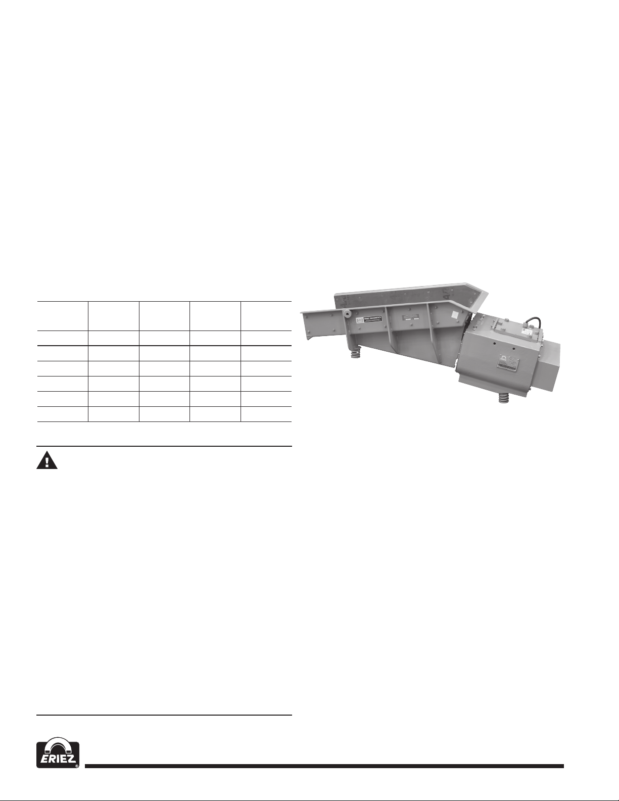
Floor Mounting
Mount front and rear of Feeder on the floor
mounting accessories provided as an alternate to
the suspension accessories. The mounting bases
(Part #27 or #28) should be bolted to the floor or other
mounting surface, and the unit, with the floor mounting
springs (Part #24, 25, or 26 on part list), simply placed
on the bases (no fastening necessary). (See Figure 1)
FIGURE 1
WARNING
Suspension mounting inherently involves
risk of property damage or personal injury to
equipment or personnel located under or near
the machine, should a mounting cable fail.
Suspension component specifications given
in this manual are suggestions only, and final
selection of suspension method is entirely
the responsibility of the user. Select and
use suspension cables with rated capacities
(including reduction factors for clamps, etc.)
that provide adequate safety factors when
the weight of the equipment and all possible
loading conditions and upsets are taken
into account. Consult Eriez at 814-835-6000
if additional Eriez equipment information is
needed to make this selection. As with all
suspended equipment, access to the area
under the machine should be restricted.
Combined Suspension and Floor Mounting
Any combination of suspension and floor mounting
means may be utilized. The details of any such
combination will, of course, be dictated by the
particular application. The instructions given above
should be followed.
IMPORTANT NOTE:
Special Trays and Attachments
Eriez engineering service should always be consulted
before undertaking the design or construction of
special trays. Neither standard nor special trays as
furnished by Eriez Magnetics should be modified or
attachments made without first consulting us. (See
Eriez Standard Tray Specifications.) Unauthorized
alterations void Eriez’ warranty.
4
 Loading...