

Eriez 36C Installation, Operation And Maintenance Instructions

Installation, Operation
and Maintenance
Instructions
VM-3155D
ERIEZ MAGNETICS HEADQUARTERS: 2200 ASBURY ROAD, ERIE, PA 16506–1402 U.S.A.
WORLD AUTHORITY IN SEPARATION TECHNOLOGIES
VIBRATORY
FEEDER
MODEL 36C

Introduction
This manual details the proper steps for installing,
operating and maintaining the Eriez Vibratory Feeder.
Careful attention to these requirements will assure the most
efficient and dependable performance of this equipment.
If there are any questions or comments about the manual,
please call Eriez at 814-835-6000 for Vibratory Feeder assistance.
CAUTION
Safety labels must be affixed to this product.
Should the safety label(s) be damaged, dislodged
or removed, contact Eriez for replacement.
© 2015 ERIEZ MAGNETICS ALL RIGHTS RESERVED
2

Table of Contents
ERIEZ VIBRATORY FEEDER - MODEL 36C
INSTALLATION .....................................................................................................4
Mounting .......................................................................................................... 4
Electrical Connections ..................................................................................... 4
OPERATION AND MAINTENANCE ...................................................................... 4
Tuning Guide ...................................................................................................4
How To Measure Displacement ....................................................................... 5
Tuning for Non-standard Trays ........................................................................ 5
Tuning for Different Conditions of Tray Loading .............................................. 6
REPAIRS ............................................................................................................... 6
Coil Replacement ............................................................................................ 6
Spring Change or Replacement ...................................................................... 7
Armature Replacement .................................................................................... 8
The Hi-Vi Magnetic Drive Circuit ...................................................................... 8
TROUBLESHOOTING ........................................................................................ 10
STORAGE ........................................................................................................... 11
Vibratory Feeder: Model 36C
3
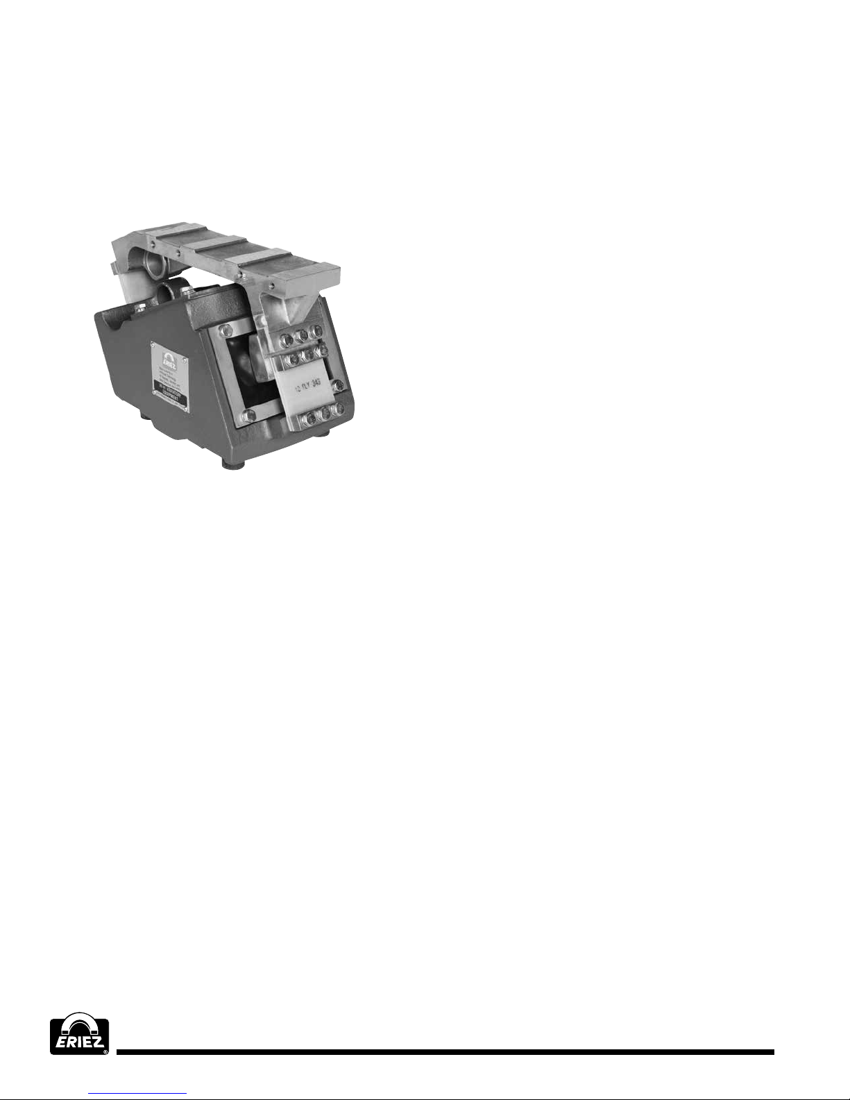
Installation
Mounting
This Hi-Vi model should be mounted on a flat surface
and fastened with bolts or screws of proper size.
Use lock washers under the bolt heads.
FIGURE 1
Electrical Connections
NOTE: The Eriez Vibratory Feeder is designed to be
operated from an AC source. It cannot be operated
from a DC source.
All wiring should conform to all applicable
electrical codes.
1. Check the specifications of the power line to be
certain that they are the same as those shown on
the nameplate.
2. Connect the black and white wires in the feeder
power cord to the power source or to the proper
terminals in the control box.
3. Connect the green wire to the ground or to the
lug provided in the control box.
4. If using a control box, make all connections as
indicated on the control wiring diagram.
5. Connect the ground lug in the control box to a
good earth ground (a cold water line is excellent).
6. On multiple drive feeders (two or more drives on
one tray) all drives should be wired electrically in
phase and in parallel.
The black wires from each power cord should be
connected together and the white wires connected
together. The black wires should be connected
to the line side of the input voltage and the white
wires should be connected to the neutral side.
You are now ready to start your vibratory feeder.
Operation & Maintenance
Do not operate the unit with associated equipment
touching any part of the unit.
To start the feeder after all connections have been
made, apply power to the line connected to the feeder.
If a controller is used, operate the switch on the
controller and adjust the output voltage to maximum
by rotating the control knob to the full clockwise
position. Ordinarily (at ordinary room temperatures)
the unit will take about two minutes to reach full
steady-state displacement.
After full steady-state displacement has been attained,
use the controller to adjust the unit to the desired
feed rate.
No routine maintenance or lubrication is required,
except that any accumulation of foreign matter should
be periodically removed from between the tray-tiebar
assembly and the body, and from between the body
and the mounting surface, to prevent restriction of
movement of the vibratory elements.
IMPORTANT NOTE:
Special Trays and Attachments
Eriez engineering service should always be consulted
before undertaking the design or construction of
special trays. Neither standard nor special trays as
furnished by Eriez should be modified or attachments
made without first consulting us. Not doing so will void
warranty. (See Standard Tray Specifications.)
TUNING GUIDE
General Information
The tuning means is provided solely for the purpose
of mechanically tuning the unit, with its tray, to the
desired vibratory displacement at full voltage. When
a unit is furnished complete with tray, it is properly
tuned to the tray at the factory. Such tuning is naturally
somewhat different for trays of different size or weight.
4
 Loading...