

Page 1

© 2017 erie water treatment TM-EN-SOF-WHF-Rev2017.01
Technical Manual
WHOLEHOUSE WATER FILTER
Models: SOF-WHF-
Page 2

TABLE OF CONTENT
Page 2
Table of content ...................................................................................................................Page 2
Warning & Safety instructions ..............................................................................................Page 3
Operating conditions & Requirements .................................................................................Page 4
Installation ...........................................................................................................................Page 5
Commissioning .....................................................................................................................Page 6
Electronic control panel .......................................................................................................Page 7
Maintenance ........................................................................................................................Page 10
Troubleshooting ...................................................................................................................Page 12
Electrical wiring diagram ......................................................................................................Page 13
Default configuration parameter settings.............................................................................Page 14
Exploded view - System ........................................................................................................Page 15
Exploded view - Timer assembly ..........................................................................................Page 17
Exploded view - Valve body ..................................................................................................Page 19
Technical data ......................................................................................................................Page 21
Page 3

WARNING & SAFETY INSTRUCTIONS
Page 3
Before you begin the installation of the appliance, we advise you read
and carefully follow the instructions contained in this manual. It contains
important information about safety, installation, use and maintenance of
the product. The actual system that you have received, may differ from
the pictures/illustrations/descriptions in this Technical Manual.
Failure to follow the instructions could cause personal injury or damage
to the appliance or property. Only when installed, commissioned and
serviced correctly, the appliance will offer you many years of trouble-free
operation.
The appliance is intended to 'filter' the water, meaning it will remove
specific undesired substances; it will not necessarily remove other
contaminants present in the water. The appliance will not purify polluted
water or make it safe to drink!
Installation of the appliance should only be undertaken by a competent
person, aware of the local codes in force. All plumbing and electrical
connections must be done in accordance with local codes.
Before setting up the appliance, make sure to check it for any externally
visible damage; do not install or use when damaged.
Use a hand truck to transport the appliance. To prevent accident or
injury, do not hoist the appliance over your shoulder. Do not lay the
appliance on its side.
Keep this Technical Manual in a safe place and ensure that new users are
familiar with the content.
The appliance is designed and manufactured in accordance with current
safety requirements and regulations. Incorrect repairs can result in
unforeseen danger for the user, for which the manufacturer cannot be
held responsible. Therefore repairs should only be undertaken by a
competent technician, familiar and trained for this product.
In respect of the environment, the appliance should be disposed of in
accordance with Waste Electrical and Electronic Equipment
requirements. Refer to national/local laws and codes for correct recycling
of this appliance.
Page 4

OPERATING CONDITIONS & REQUIREMENTS
Page 4
OPERATING PRESSURE MIN-MAX: 2,0-8,3 bar / 29-120 psi
check water pressure regularly; it may fluctuate severely
depending on the time of day, the day of the week or even the
season of the year.
take into account that night time water pressure may be
considerably higher than day time water pressure.
install a pressure reducer ahead of the appliance if necessary.
install a pressure booster, if it is likely that water pressure may
drop below the minimum.
OPERATING TEMPERATURE MIN-MAX: 2-48 °C / 36-120 °F
do not install the appliance in an environment where high
ambient temperatures (e.g. unvented boiler house) or freezing
temperatures can occur.
the appliance cannot be exposed to outdoor elements, such as
direct sunlight or atmospheric precipitation.
do not install the appliance too close to a water heater; keep at
least 3 m (10 ft) of piping between the outlet of the appliance
and the inlet of the water heater; water heaters can sometimes
transmit heat back down the cold pipe into the appliance;
always install a check valve at the outlet of the appliance.
ELECTRICAL CONNECTION:
the appliance only works on 24 VAC; always use it in
combination with the supplied transformer.
make sure to plug the transformer into a power outlet, which is
installed in a dry location, with the proper rating and overcurrent protection.
Page 5
INSTALLATION
Page 5
INLET & OUTLET
We strongly recommend the use of flexible hoses to
connect the appliance to the water distribution system; use
hoses with a large diameter in order to limit the pressure
loss.
If the appliance is not equipped with the factory bypass
(optional), we strongly recommend to install a 3-valve
bypass system (not included with this product!) to isolate the
appliance from the water distribution system in case of
repairs. It allows to turn off the water to the appliance, while
maintaining (untreated) water supply to the user.
WITH FACTORY BYPASS (optional)
Picture 1
= mains water supply (untreated water)
= inlet of appliance (untreated water)
= outlet of appliance (treated water)
= house/application (treated water)
1. Screw the factory bypass onto the in/out ports on the
control valve (&); make sure to install the gasket
seals. Tighten the nuts firmly by hand.
2. Screw the connection kit with nuts onto the factory
bypass (&); make sure to install the gasket seals.
Tighten the nuts firmly by hand.
3. Connect the mains water supply to the adaptor on the
inlet port of the factory bypass ().
4. Connect the house/application to the adaptor on the
outlet port of the factory bypass ().
WITH 3-VALVE BYPASS SYSTEM (not included)
Picture 2
= inlet of appliance (untreated water)
= outlet of appliance (treated water)
1. Install the 3-valve bypass system.
2. Screw the connection kit with nuts onto the in/out ports
on the control valve (&); make sure to install the
gasket seals. Tighten the nuts firmly by hand.
3. Connect the 3-valve bypass system to the adaptors on the
in () and out () port of the control valve.
4. Connect the mains water supply to the inlet of the 3-valve
bypass system.
5. Connect the house/application to the outlet of the 3-valve
bypass system.
DRAIN
We recommend the use of a stand pipe with P-trap.
To prevent backflow from the sewerage system into the
appliance, always install and use the included drain adaptor
with air gap and double hose barb, to connect the drain hose
to the sewerage system.
Lay-out the drain hose in such a way that pressure loss
is minimized; avoid kinks and unnecessary elevations.
Make sure that the sewerage system is suitable for the
rinse water flow rate of the appliance.
Picture 3
1. Install the drain adaptor to the sewerage system; it fits
over a 32 mm pipe or inside a 40 mm pipe adaptor. Ensure
a permanent and watertight connection.
2. Connect a 13 mm hose to the drain connection of the
control valve (); secure it by means of a clamp.
3. Run the drain hose to the drain adaptor and connect it to
one of the hose barbs; secure it by means of a clamp. This
drain line operates under pressure, so it may be installed
higher than the appliance.
Page 6
COMMISSIONING
Page 6
ELECTRICAL
Picture 4
1. Plug the transformers output lead into the socket on the
control valves power cord; secure it by means of the
TwistLock clamp.
2. Plug the transformer into an electrical outlet.
PRESSURIZING
1. Make sure the bypass system is in 'bypass' position.
2. Make sure the electronic controller of the appliance is in
service mode.
3. Open the mains water supply.
4. Open a cold treated water faucet nearby the appliance
and let the water run for a few minutes until all air is
purged and all foreign material that may have resulted
from the installation is washed out; close the tap.
5. Gently pressurize the appliance, by putting it into service:
factory bypass:
1. open the 'outlet' valve;
2. slowly open the 'inlet' valve.
3-valve bypass:
1. close the 'bypass' valve;
2. open the 'outlet' valve;
3. slowly open the 'inlet' valve.
6. After 2-3 minutes, open a cold treated water faucet
nearby the appliance and let the water run until all air is
purged from the installation and the filter media is
properly rinsed (it is normal for the rinse water to show
some discoloration!); let the water run until the rinse
water is clear; close the tap.
7. Check the appliance and all hydraulic connections for
leaks.
ELECTRONIC CONTROL PANEL
1. Program the electronic controller.
PERFORM REGENERATION
1. Manually initiate a regeneration, by pressing the scroll
button; the display will show:
2. Leave the appliance in this position; the countdown timer
will countdown to 0 sec and start a regeneration.
Regen in 10 sec
Page 7
ELECTRONIC CONTROL PANEL
Page 7
Picture 5
POWER-UP
After power-up the display will show the installed software
version for a period of 5 seconds.
POWER FAILURE
In the event of a power failure, the program will remain
stored in the NOVRAM® during an undefined period, while an
incorporated SuperCap will maintain the correct time of day
during a period of several hours; consequently, in case of
prolonged power failure, the time of day might not be
maintained; if this happens, the time of day will be reset to
8:00 when the power supply is re-established, while the
indication will flash, indicating that the time of day needs to
be set.
When the power failure occurs during the execution of an
automatic regeneration, the control valve will remain in its
last position; when the power supply is re-established, the
control valve will return to the service position, stay there for
60 sec. and restart a complete regeneration from the
beginning.
TIMER FAILURE
In the event of a timer failure, the display will show the
message:
If powering off/on the appliance doesn’t solve this problem,
professional service is required.
MAINTENANCE REMINDER
Only available if the maintenance reminder function has
been activated and programmed by your supplier!
Once the maintenance interval is reached, the display will
intermittently show the message:
While the appliance will continue to operate normally, it is
recommended to have preventive maintenance performed
by a professional.
SERVICE MODE
In service mode the display shows the time of day and the
number of days remaining until the next regeneration:
REGENERATION MODE
In regeneration mode the display shows the remaining
regeneration time and the remaining cycle time:
The appliance can be reset to service mode at any time by
pressing the scroll button, as such manually advancing it
through the regeneration cycles.
MANUAL REGENERATION
It is possible to manually initiate an immediate regeneration
or a delayed regeneration (at the preprogrammed time of
regeneration).
1. Press the scroll button; the display will show:
If the control panel is left in this position, the
countdown timer will countdown to 0 sec and start an
immediate regeneration.
To cancel this mode, press the scroll button before
the countdown timer has reached 0 sec; the display
will show:
If the control panel is left in this position, a delayed
regeneration will be started at the indicated
preprogrammed time of regeneration.
To cancel this mode, press the scroll button; the
control panel will return to the service mode.
HOLIDAY MODE
It is possible to put the appliance in holiday mode; this will
prevent automatic regeneration from taking place, yet will
ensure the appliance is automatically regenerated at the end
of the holiday cycle.
1. Press the scroll button repeatedly until the display
shows:
Press the up or down button to activate the
holiday mode by setting the number of full days away
from home, or deactivate the holiday mode (OFF).
Once the control panel is back in service mode, the display
will show:
The holiday mode is automatically cancelled when a
regeneration is manually initiated!
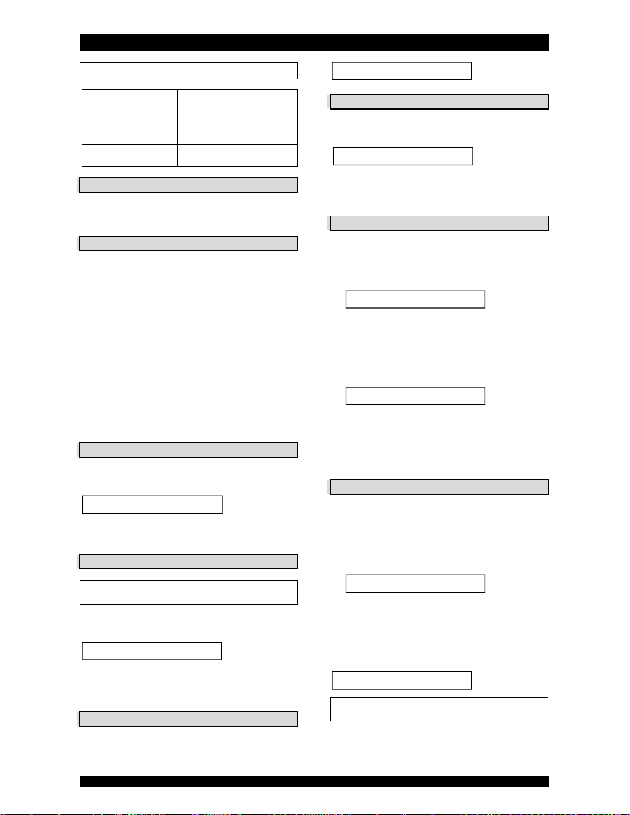
symbol
button
function
SCROLL
to advance to the next
parameter
UP
to increase the value of the
parameter
DOWN
to decrease the value of the
parameter
Service Required
Rgn:XXX CycY:ZZZ
8:01 7 DAY REM
Maintenance Now
Regen in 10 sec
Regen @ 2:00
Holiday: OFF
8:01 Holiday
Page 8

ELECTRONIC CONTROL PANEL
Page 8
PROGRAMMING INSTRUCTIONS -
BASIC SETTINGS
Before entering the programming mode, make sure that
the appliance is in the service mode.
In case no button is pressed in a period of 5 min, the
control panel will automatically return to the service mode;
any changes made will NOT be saved!
1. Press the scroll button and hold it for 2 sec until the
display shows:
Press the up or down button to set the
language.
2. Press the scroll button again; the display will show:
Press the up or down button to set the time of
day.
3. Press the scroll button again; the display will show:
Press the up or down button to set the number
of days between regenerations.
4. Press the scroll
button again; the display will show:
Press the up or down button to save the settings
into the NOVRAM® and exit the programming mode.
The regeneration cycle is necessary to wash out
impurities that are captured in the filter media during the
service cycle, and to prevent ‘caking’ of the filter media,
which may result in an increase of pressure drop over the
appliance. Typically a regeneration every 7 days should be
sufficient. In case of high flow rates, excessive water usage
or a high concentration of impurities in the incoming water,
it may be necessary to lower the number of days between
regenerations.
PROGRAMMING INSTRUCTIONS -
CONFIGURATION PARAMETERS
Before entering the programming mode, make sure that
the appliance is in service mode.
All configuration parameters on this appliance have
been pre-programmed in the factory, to offer optimal
performance in a wide range of applications and situations.
Nevertheless it may be necessary or desirable to change any
of these parameters, to further optimize the appliances
performance or to adapt it to the specific requirements of
the installation.
In case no button is pressed in a period of 5 min, the
control panel will automatically return to the service mode;
any changes made will NOT be saved!
1. Press the scroll button and hold it for 6 sec until the
display shows:
2. Within 10 sec, press the up button; the display will
show:
Press the up or down button to set the units of
measure (Metric or US).
3. Press the scroll button again; the display will show:
Press the up or down button to activate the
maintenance reminder function by setting the
maintenance interval, or deactivate the maintenance
reminder function.
4. Press the scroll button again; the display will show:
Press the up or down button to set the length
of the regeneration cycle.
Press the scroll button again to advance to the next
regeneration cycle.
Cycle 1
Backwash
Cycle 2
No function
Cycle 3
Fast rinse
5. Press the scroll button again; the display will show:
Press the up or down button to set the time of
regeneration.
6. Press the scroll button again; the display will show:
Press the up or down button to save the settings
into the NOVRAM® and exit the programming mode.
Regen @ 0:00
Exit
Language:English
Set time: 8:01
Interval:7 Days
Exit
Cycle 1: XX min
System Check
MaintInt: OFF
Units:Metric
Page 9
ELECTRONIC CONTROL PANEL
Page 9
DIAGNOSTICS MODE
In the Diagnostics mode several operating parameters
can be consulted; particularly during a service intervention,
these parameters can be helpful to identify the cause of a
problem or malfunction.
Before entering the Diagnostics mode, make sure that
the appliance is in service mode.
In case no button is pressed in a period of 5 min, the
control panel will automatically return to the service mode!
Accessing the Diagnostics mode
1. Press the scroll button and hold it for 6 sec until the
display shows:
2. Within 10 sec, press the down button; the display will
show:
You are now in the Diagnostics mode.
Press the scroll button to advance to the next
diagnostics parameter.
Available diagnostics parameters
Regen X days ago: number of days since last
regeneration.
In Srvc: total number of days in service.
# of Regens: number of regenerations since installation.
Regen @: setting of time of regeneration.
Interval: setting of number of days between
regenerations.
Cycle X: setting of length of corresponding regeneration
cycle.
Units: control is programmed for Metric units.
Regen: setting of the regeneration mode.
Valve Type: setting of valve type.
MP Resets: number of resets of microprocessor (for
factory purpose only).
Memory Reset: number of corrupt memory start-ups (for
factory purpose only).
EZRFTg EZDRV r02: software version.
Exiting the Diagnostics mode
1. Press the scroll button repeatedly until the display
shows:
Press the up or down button to exit the
Diagnostics mode.
Exit
Regen XXdays ago
System Check
Page 10
MAINTENANCE
Page 10
RECOMMENDATION
Notwithstanding the reliability of the appliance, we strongly
recommend to have it serviced and maintained on a regular
basis by a competent and duly trained technician. He will be
able to determine the appropriate maintenance interval for
the appliance, depending on your specific application and the
local operating conditions. The advantages of performing
regular maintenance are:
regular check of the local operating conditions (water
quality, pressure, etc);
regular control and adjustment of the settings of the
appliance, to guarantee it operates at maximum
efficiency;
minimize the risk of unexpected break-down.
Contact your dealer or installer for more information, or visit
our website.
ROUTINE CHECKS
Regularly the user should perform a basic check to verify if the
appliance is functioning correctly, on the basis of the
following control points:
1. Check settings of electronic control panel.
2. Check water composition before/after appliance.
3. Check drain line from control valve; there shouldn’t be
any water flow (unless appliance is in regeneration).
4. Check appliance and surrounding area; there shouldn’t be
any water leakages.
BYPASSING THE APPLIANCE
Occasionally it may be necessary to put the appliance
hydraulically in bypass, i.e. to isolate it from the water
distribution system; f.e.:
in case of an urgent technical problem;
when it is not necessary to supply treated water to the
house/application (refill swimming pool, irrigation,...).
WITH FACTORY BYPASS (optional)
Picture 6.a
SERVICE POSITION
= inlet valve to appliance is OPEN
= outlet valve from appliance is OPEN
Picture 6.b
BYPASS POSITION
= inlet valve to appliance is CLOSED
= outlet valve from appliance is CLOSED
Picture 6.c
MAINTENANCE POSITION
= inlet valve to appliance is OPEN
= outlet valve from appliance is CLOSED
WITH 3-VALVE BYPASS SYSTEM (not included)
Picture 7.a
SERVICE POSITION
= bypass valve is CLOSED
= inlet valve to appliance is OPEN
= outlet valve from appliance is OPEN
Picture 7.b
BYPASS POSITION
= bypass valve is OPEN
= inlet valve to appliance is CLOSED
= outlet valve from appliance is CLOSED
Picture 7.c
MAINTENANCE POSITION
= bypass valve is OPEN
= inlet valve to appliance is OPEN
= outlet valve from appliance is CLOSED
SANITIZING THE APPLIANCE
This appliance is manufactured from premium quality
material and assembled in safe conditions to assure it is clean
and sanitary. If installed and serviced correctly, this appliance
will not infect or contaminate your water supply. However, as
in any 'device' plumbed-in in your water distribution system,
a proliferation of bacteria is possible, especially in case of
'stagnant water'. Therefore this appliance will automatically
rinse the filter media periodically.
If the power supply to the appliance is disconnected for a
longer period of time, we recommend, when the power
supply is re-established, to manually initiate a complete
regeneration.
Page 11
TROUBLESHOOTING
Page 11
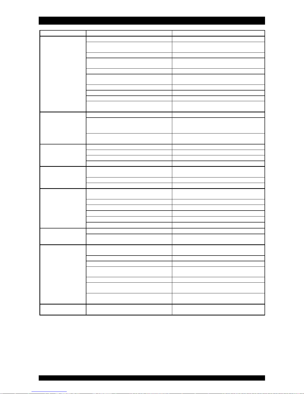
PROBLEM
CAUSE S
OLUTION
Untreated water to
service
Open or defective bypass
Close
or replace
bypass
Appliance
in regeneration
Wait until regeneration finishes or
manually
advance regeneration to end
Excessive water usage
Initiate regeneration manually
Change in raw water hardness
Verify
composition
of incoming
untreated
water
and adjust regeneration frequency accordingly
Appliance
fails to
r
egenerat
e Refer to problem “
Appliance
fails to
regenerate
” Appliance
fails to backwash properly
Refer to problem “
Appliance
fails to
backwash
properly”
V
alve body and timer out of synchronisation
Synchronize valve body and timer
Decreasing
filter capacity of
filter media
Clean or replace filter media
Loss of
filter media
Refer to problem “Loss of
filter media
”
Leak at riser tube
Verify that riser tube is seated correctly and is not
cracked
Low levels of
contaminant in treated
water
Bypass not completely closed
Close bypass
Excessive service flow rate
Lower service flow rate
Increase filter capacity by increasing volume of filter
media
Leak at riser tube
Verify that riser tube is seated correctly and is not
cracked
Appliance
fails to
regenerate
Faulty electrical supply
Verify electrical service (fuse, transformer,...)
Defective PCB
Replace PCB
Defective
drive motor
Replace
drive motor
Regeneration frequency not programmed
Program regeneration frequency
Loss of water pressure
Mineral or iron build
-
up in resin tank
Clean resin bed and control valve; increase
regeneration frequency
Plugged lower and/or upper distributor
Verify that distributors are free of debris
Crushed lower and/or upper distributor
Replace distributor(s)
Drain line from control
valve flows
continuously
Appliance
in regeneration
Wait until regeneration finishes or
manually
advance regeneration to end
Faulty electrical supply
Verify electrical service (fuse, transformer,...)
Defective drive motor
Replace drive motor
Defective micro switch
Replace micro switches
Defective PCB
Replace PCB
Valve body and timer out of synchronisation
Synchronize valve body and timer
Loss of
filter media
Lower and/or upper distributor damaged
Replace distributor(s)
Leak between riser tube and upper distributor
Verify that riser tube is seated correctly and is not
cracked
Appliance fails to
backwash properly
Low operating pressure
Check operating pressure; must be higher than
2,0
bar
Insufficient water supply
Check water supply (flow rate/dynamic pressure)
Restricted drain line
Verify drain line for kinks or restrictions
Excessive b
uild-up of impurities
in
pressure
tank Clean or replace
filter media
and control valve;
increase regeneration frequency
Plugged backwash flow control
Clean or replace backwash flow control
Plugged top or bottom distributor
Verify that top and bottom
distributor are clean and
slots are not clogged by iron or other impurities
Filter media is completely ‘caked’ (solid block)
Replace filter media and reduce regeneration
interval
Control valve cycles
continuously
Defective micro switch
Replace micro
switches
Page 12
ELECTRICAL WIRING DIAGRAM
Page 12
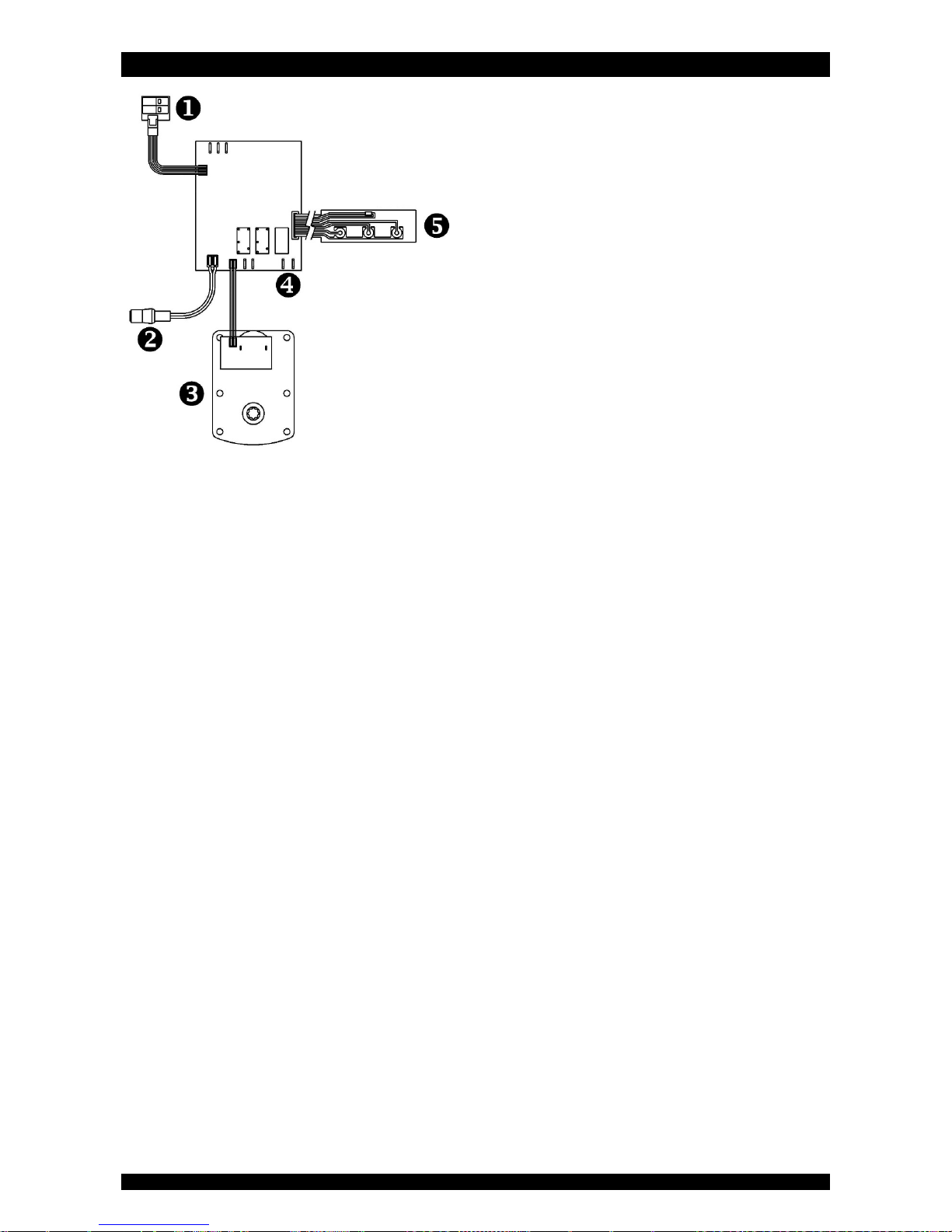
= position switches
= power lead
= drive motor
= auxilliary contact (24 VAC, max. 500mA)
= key pad
Page 13

DEFAULT CONFIGURATION PARAMETER SETTINGS
Page 13
Model SOF-WHFFilter media 12 26
44 Units
Metric Metric Metric
MaintInt (mths)
OFF OFF OFF
Cycle 1: BACKWASH (min) 5 5 5
Cycle 2: SLOW RINSE (min) 0 0 0
Cycle 3: PURGE (min) 2 2 2
Regen @ 0:00 0:00 0:00
Page 14
EXPLODED VIEW - SYSTEM
Page 14
Page 15
EXPLODED VIEW - SYSTEM
Page 15
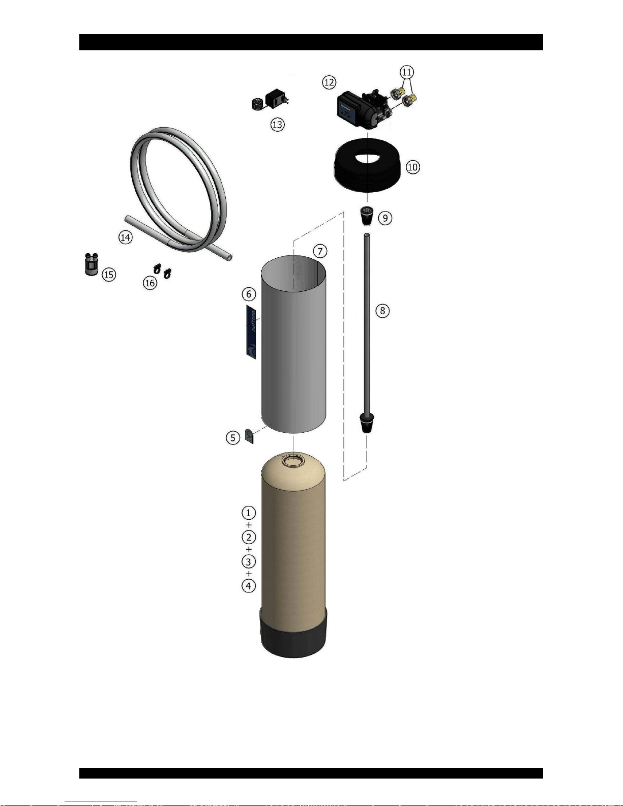
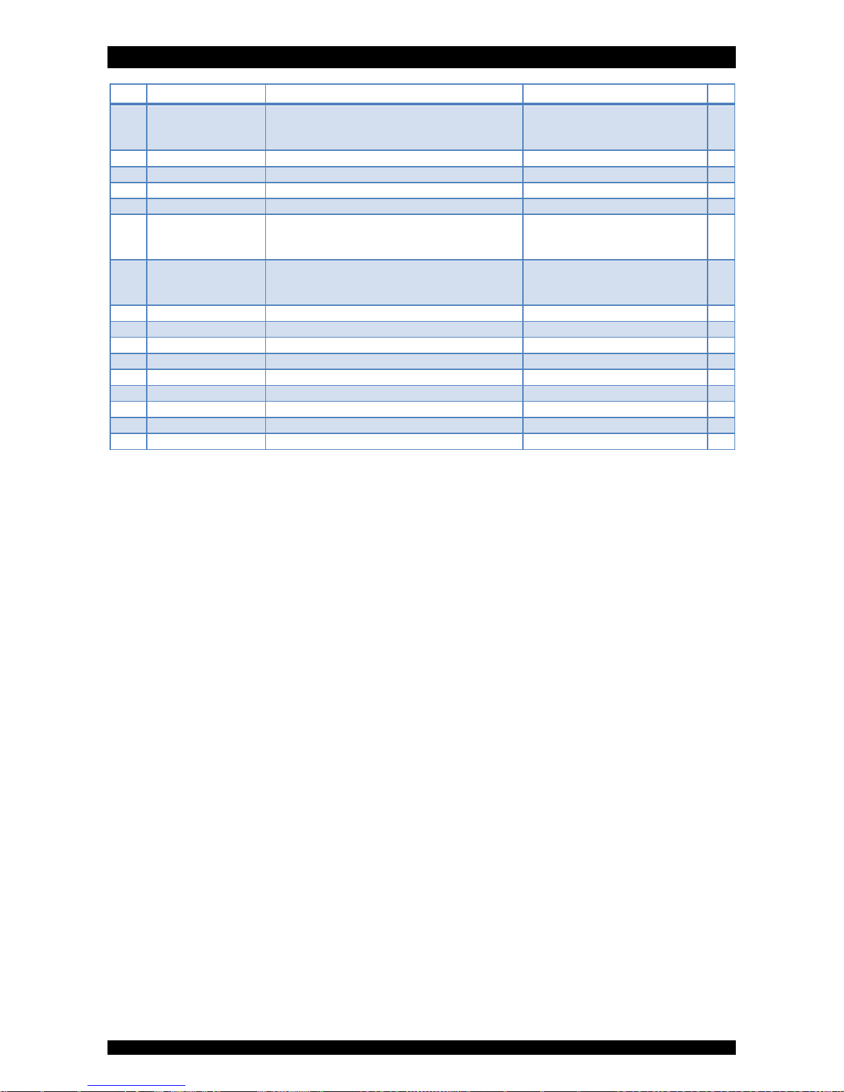
Item PN Description Remark (*)
1 PT/1018/BA Pressure tank, 10x18 12L
PT/1035/BA Pressure tank, 10x35 26L
PT/1054/BA Pressure tank, 10x54 44L
2 A1100(BB) Coconut Granular Activated Carbon (GAC) multiple of 1 cuft
3 A2000 Quartz sand multiple of 25 kg (=17 ltr)
4 A1000 Gravel multiple of 25 kg (=17 ltr)
5 39004 Dome label ‘erie water treatment’
6 39099 Label ‘Softena’ (mini) 12L
39100 Label ‘Softena’ (midi) 26L
39101 Label ‘Softena’ (maxi) 44L
7 J/1018(W) Tank jacket 10x18, white 12L
J/1035(W) Tank jacket 10x35, white 26L
J/1054(W) Tank jacket 10x54, white 44L
8 38534 Riser tube assembly to be cut to length
9 287/166/LS Top distributor
10 J/10 Tack cover
11 568/303/1 Connection kit 1” BSP male
12 2400TF/JM/AUX/MAX Control valve
13 28/298/11 Transformer 230/24V - 50 Hz, 24VA, EuroT plug
14 38522 Drain hose to be ordered per meter
15 74163 Air gap with double hose barb
16 38521 Clamp, drain hose (2x)
(*) Recommended Spare Part
Page 16
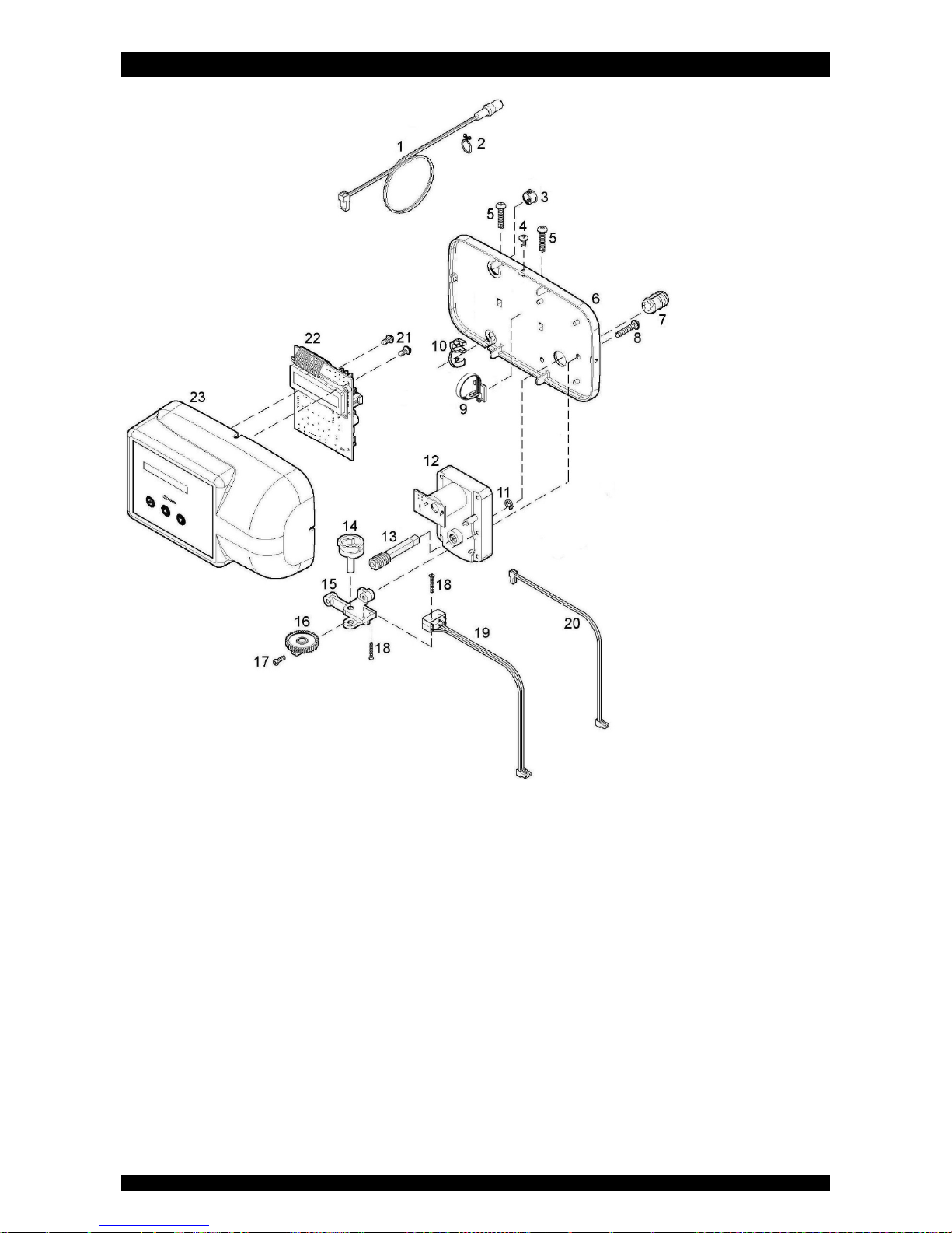
EXPLODED VIEW - TIMER ASSEMBLY
Page 16
Page 17
EXPLODED VIEW - TIMER ASSEMBLY
Page 17
(*) Recommended Spare Part
Item PN Description Remark (*)
1 70971 Power lead with plug
2 72263 Clamp
3 28/244/1 Plug (large)
4 71502 Screw, timer cover (3x)
5 15/222 Screw, back plate (2x)
6 70962 Back plate
7 75157 Worm coupling
8 15/222 Screw, drive motor assembly (2x)
9 74267 Cable clamp
10 70312 Strain relief, power lead
11 75158 Retaining ring, worm drive shaft
12 72261 Drive motor
13 75156 Worm drive shaft
14 70965 Switch cam
15 568/386 Bracket, micro switches
16 568/310 Gear, switch cam
17 15/184/7 Locking screw, switch cam
18 15/173/12 Screw, micro switches (2x)
19 72451 Micro switch assy
20 71679 Cable set, drive motor
21 15/102 Screw, PCB (2x)
22 72703 Printed Circuit Board
23 74274 Timer cover assembly ‘Softena’
Page 18
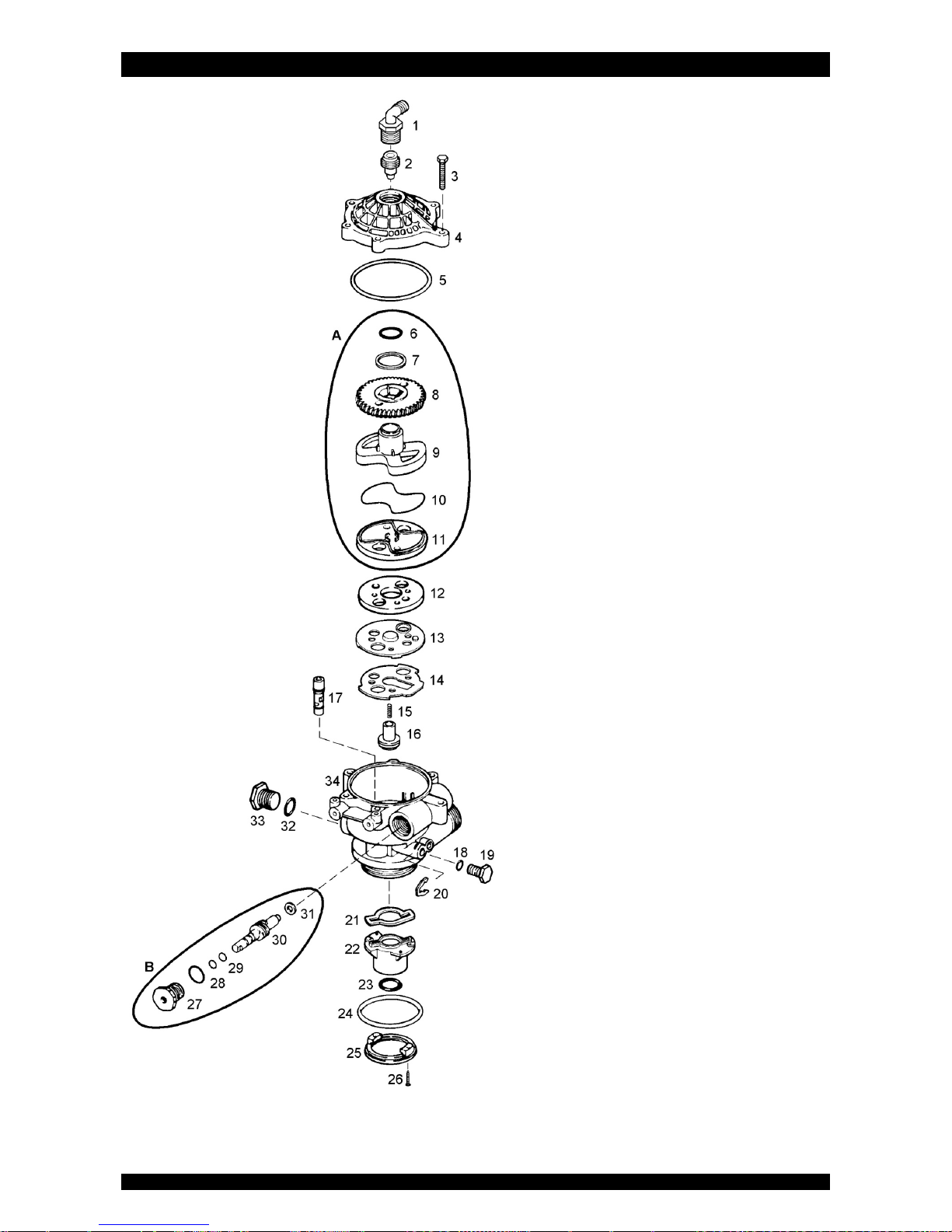
EXPLODED VIEW - VALVE BODY
Page 18
Page 19

EXPLODED VIEW - VALVE BODY
Page 19
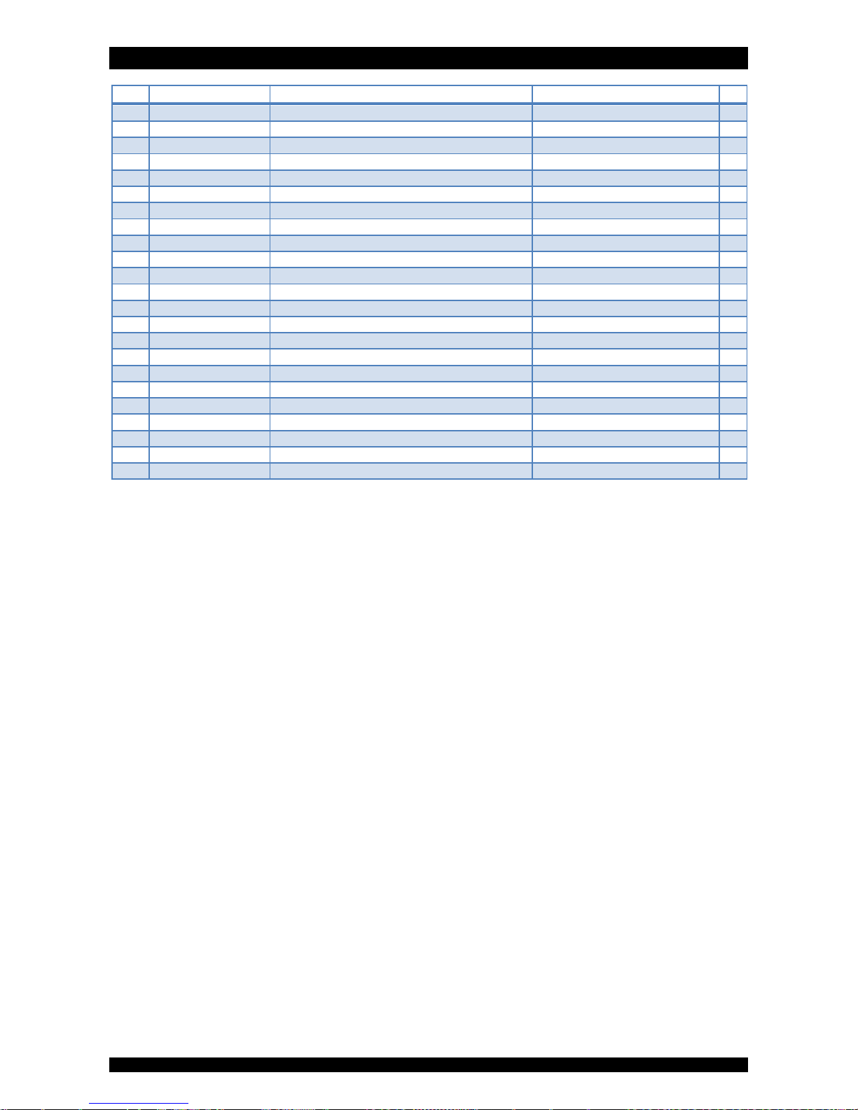
Item PN Description Remark (*)
1 21/83 Drain connection
2 568/271/M Backwash flow control M (18,9 ltr/min)
3 72678 Bolt, valve cover (6x)
4 568/254/3 Valve cover
5 185/154/1 O-ring, valve cover
6 186/112 O-ring, Teflon
7 72327 Washer, PE
8 568/260 Worm gear
9 568/259 Rotor cam
10 185/041/1 O-ring, rotor
11 568/345/2 Rotor plate
12 568/256 Seal disk
13 568/383 Insert plate
14 568/384 Gasket
15 51/5/105 Spring, float valve
16 568/270/4 Float valve
17 568/274/5 Injector (green)
18 186/118 O-ring, plug (small)
19 541/273 Plug (small)
20 541/254 Spring clip, plug (small)
21 570/251 Gasket, riser
22 568/334 Riser insert
23 185/214/1 O-ring, riser tube
24 185/337/1 O-ring, tank
25 541/232 Adapter ring
26 15/207/12 Screw, adapter ring (2x)
27 72772 Packing gland nut (plastic)
28 185/211/1 O-ring, packing gland nut
29 186/115 O-ring, worm drive shaft (2x)
30 568/208/2 Worm drive shaft
31 14/43 Washer, worm drive shaft
32 185/208/1 O-ring, plug (large)
33 21/72/3 Plug (large)
34 72800 Valve body
A RK/568/259/2 Repair kit rotor
B RK/75154 Repair kit packing gland nut
(*) Recommended Spare Part
Page 20
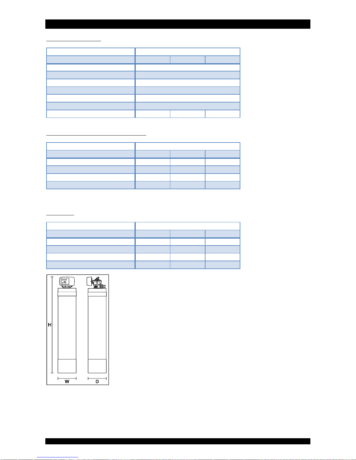
TECHNICAL DATA
Page 20
Technical specifications:
Model SOF-WHFFilter media (cuft) 12 26 44
Operating pressure min/max (bar) 2,0/8,3
Operating temperature min/max (°C) 2/48
Electrical connection (V/Hz) 230/50
(1)
Max. power consumption (VA) 12
Hydraulic connection inlet/outlet 1” BSP Male
Hydraulic connection drain 13 mm hose barb
Pressure tank 10x18 10x35 10x54
(1) Supplied with 24V transformer
Performances @ 3 bar operating pressure
(2)
:
Model SOF-WHFFilter media (cuft) 12 26 44
Service flow rate @∆p 1 bar (m³/hr)
(3)
3,6 3,4 3,2
Recomm. max. service flow (m³/hr)
(4)
1,0 1,2 1,4
Rinse water usage per regeneration (ltr) 132 132 132
Backwash flow rate (ltr/min) 19 19 19
(2) Indicative numbers, performances depending on operating conditions and water quality
(3) Based on clean filter bed operation
(4) Flow rate at which filtration process is still executed adequately, higher (up to x2) intermittent flow rates are possible
Dimensions:
Model SOF-WHFFilter media (cuft) 12 26 44
Width (mm) (W) 264 264 264
Depth (mm) (D) 282 282 282
Depth, incl. factory bypass (mm) (D) 371 371 371
Height (mm) (H) 629 1.065 1.554
Page 21

Page 21
Page 22

Page 22
Page 23

Page 23
Page 24

Manufactured & Assembled by
erie water treatment
a division of Aquion, Inc.
www.eriewatertreatment.com
 Loading...