


BelAir20E
BelAir20E
User Guide
Release: 12.0
Document Date: April 2, 2012
Document Number: BDTM02201-A01
Document Status: Standard
Security Status: Confidential
Customer Support: 613-254-7070
1-877-BelAir1 (235-2471)
techsupport@belairnetworks.com
© Copyright 2012 by BelAir Networks.
The information contained in this document is confidential and proprietary to BelAir Networks. Errors and Omissions Excepted.
Specification may be subject to change. All trademarks are the property of their respective owners.
Protected by U.S. Patents: 7,171,223, 7,164,667, 7,154,356, 7,030,712 and D501,195. Patents pending in the U.S. and other countries.
BelAir Networks, the BelAir Logo, BelAir200, BelAir200D, BelAir100, BelAir100S, BelAir100C, BelAir100T, BelAir20, BelAir20M, BelAir20E, BelAir20EO, BelAir100M,
BelAir100i, BelAir100SN, BelAir100SNE, BelAir100N, BelAir100P, BelView and BelView NMS are trademarks of BelAir Networks Inc.
Page 1 of 255

BelAir20E User Guide Contents
Contents
About This Document . . . . . . . . . . . . . . . . . . . . . . . . . . . . . . . . . . . 3
System Overview . . . . . . . . . . . . . . . . . . . . . . . . . . . . . . . . . . . . . . . 4
BelAir20E Configuration Interfaces . . . . . . . . . . . . . . . . . . . . . . . . . 6
Command Line Interface Basics . . . . . . . . . . . . . . . . . . . . . . . . . . . 12
BelAir20E Access Methods. . . . . . . . . . . . . . . . . . . . . . . . . . . . . . . 27
User and Session Administration . . . . . . . . . . . . . . . . . . . . . . . . . . 35
IP Settings . . . . . . . . . . . . . . . . . . . . . . . . . . . . . . . . . . . . . . . . . . . . 44
System Settings . . . . . . . . . . . . . . . . . . . . . . . . . . . . . . . . . . . . . . . . 49
BelAir20E Auto-configuration . . . . . . . . . . . . . . . . . . . . . . . . . . . . 58
Ethernet or LAN Interface Settings . . . . . . . . . . . . . . . . . . . . . . . . 64
Card Settings. . . . . . . . . . . . . . . . . . . . . . . . . . . . . . . . . . . . . . . . . . 67
Wi-Fi Radio Configuration Overview . . . . . . . . . . . . . . . . . . . . . . 71
Configuring Wi-Fi Radio Parameters . . . . . . . . . . . . . . . . . . . . . . . 72
Configuring Wi-Fi Access Point Parameters . . . . . . . . . . . . . . . . . 80
Wi-Fi AP Security . . . . . . . . . . . . . . . . . . . . . . . . . . . . . . . . . . . . . 100
Wi-Fi Backhaul Link Configuration . . . . . . . . . . . . . . . . . . . . . . . 115
Mobile Backhaul Mesh . . . . . . . . . . . . . . . . . . . . . . . . . . . . . . . . . 123
Mobile Backhaul Point-to-point Links . . . . . . . . . . . . . . . . . . . . . 127
Operating in High Capacity and Interference Environments. . . . 138
DHCP Relay Settings . . . . . . . . . . . . . . . . . . . . . . . . . . . . . . . . . . 145
Network Address Translation . . . . . . . . . . . . . . . . . . . . . . . . . . . 149
Universal Access Method . . . . . . . . . . . . . . . . . . . . . . . . . . . . . . . 154
Using Layer 2 Tunnels . . . . . . . . . . . . . . . . . . . . . . . . . . . . . . . . . 163
Quality of Service Settings . . . . . . . . . . . . . . . . . . . . . . . . . . . . . . 177
Layer 2 Network Configuration. . . . . . . . . . . . . . . . . . . . . . . . . . 183
Performing a Software Upgrade. . . . . . . . . . . . . . . . . . . . . . . . . . 197
For More Information. . . . . . . . . . . . . . . . . . . . . . . . . . . . . . . . . . 205
Technical Support. . . . . . . . . . . . . . . . . . . . . . . . . . . . . . . . . . . . . 207
Definitions and Acronyms . . . . . . . . . . . . . . . . . . . . . . . . . . . . . . 208
Appendix A: Node Configuration Sheets . . . . . . . . . . . . . . . . . . 210
Appendix B: Mesh Auto-connection Example . . . . . . . . . . . . . . 213
Appendix C: Scripting Guidelines . . . . . . . . . . . . . . . . . . . . . . . . 223
Appendix D: BelAir20E Factory Defaults . . . . . . . . . . . . . . . . . . 240
Detailed Table of Contents . . . . . . . . . . . . . . . . . . . . . . . . . . . . . 242
April 2, 2012 Confidential Page 2 of 255
Document Number BDTM02201-A01 Standard

BelAir20E User Guide About This Document
About This Document
This document provides the information you need to install and configure the
BelAir20E™, and the procedures for using the BelAir20E Command Line
Interface (CLI).
This document may contain alternate references to the product. Ta bl e 1 shows
possible synonyms to the product name.
Table 1: Product Name Synonyms
Product Name Synonym
BelAir20™, BelAir20E™, BelAir20EO™ BA20
Ty pog raph ica l Conventions
Related Documentation
This document uses the following typographical conventions:
• Text in < > indicates a parameter required as input for a CLI command;
for example, < IP address >
• Text in [ ] indicates optional parameters for a CLI command.
• Text in { } refers to a list of possible entries with | as the separator.
• Parameters in ( ) indicate that at least one of the parameters must entered.
The following titles are BelAir reference documents:
•
BelAir20E Quick Install Guide
•
BelAir20E Troubleshooting Guide
April 2, 2012 Confidential Page 3 of 255
Document Number BDTM02201-A01 Standard

BelAir20E User Guide System Overview
System Overview
The BelAir20E Access Point (AP) is an evolution of BelAir Networks indoor
solution and part of BelAir Networks industry leading product portfolio. The
BelAir20E adds standards-based beamforming, five Gigabit Ethernet ports
(one WAN port with PoE and four LAN ports), integrated antennas, and full
802.11n compliance (802.11n-2009) to BelAir Networks leading low cost, high
capacity indoor access.
The next generation BelAir20E continues to lead with the industry’s highest
performance and most flexible indoor access node. Offering all the same
features and management as the other BelAir products, the BelAir20E has been
optimized for managed hot spot applications, with Edge Policy Enforcement
using centralized control and a true Plug-and-Play architecture. And, with the
latest fully compliant 802.11n, it is ideal for even the most demanding
applications, including voice and video. The BelAir20E also provides
connectivity between indoor and outdoor networks, enabling true
standards-based seamless mobility as users move from outside to inside.
The operating temperature of the BelAir20E is -20 ºC to +45 ºC.
The BelAir20E is available in following models:
• The BelAir20E-11 contains both a 2.4 GHz radio and a 5.8 GHz radio.
• The BelAir20E-10 contains only a 2.4 GHz radio.
This document may describe 5.8 GHz radio functionality. In such case, the
descriptions apply to the BelAir20E-11 model only. They do not apply to the
BelAir20E-10 model.
The BelAir20E is available in following variants:
• The BelAir20E-11 and the BelAir20E-10 are available for the USA only.
Operators of the BelAir20E-11 and the BelAir20E-10 can set the country of
US
operation only to
transmit power levels can be set only to values that are valid for the USA.
• The BelAir20E-11R and the BelAir20E-10R are available for countries other
than the USA. Operators of the BelAir20E-11R and the BelAir20E-10R can
set the country of operation to any BelAir approved country. Similarly, the
operating channels, antenna gain, and the transmit power levels can be set
to values that are valid for the specified country of operation.
. Similarly, the operating channels, antenna gain, and the
April 2, 2012 Confidential Page 4 of 255
Document Number BDTM02201-A01 Standard
BelAir20E User Guide System Overview
HTME
5.8 GHz
Radio
AC Power
Adapter
Antenna 0
LAN
48 V DC
Antenna 1 Antenna 2
2.4 GHz
Radio
100-240 V AC
Reset
Antenna 3
WAN
PoE
LAN LAN LAN
-11 model only
-11 model only
-11 model only
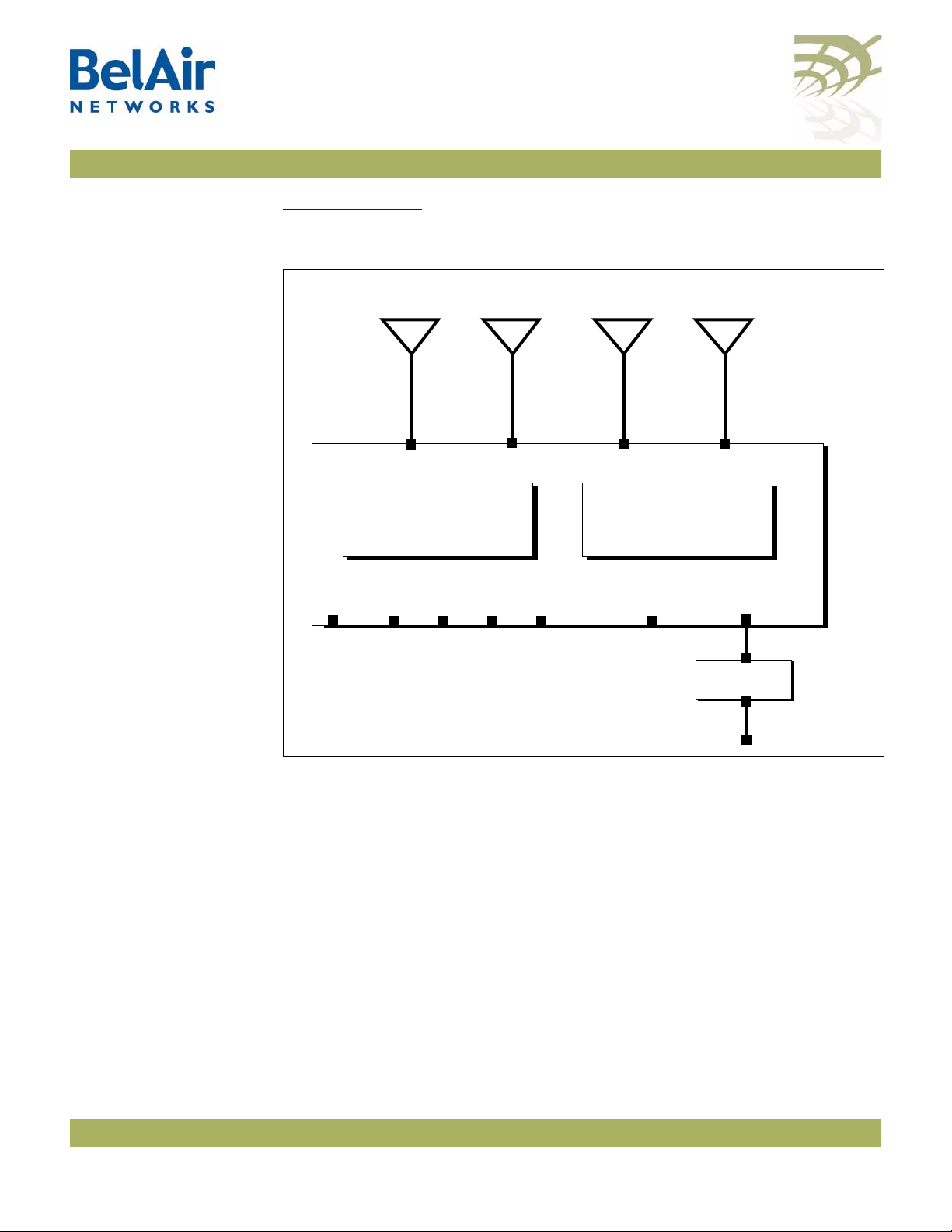
Hardware Description
Figure 1 on page 5 shows the relationship between the main BelAir20E
hardware modules.
Figure 1: BelAir20E Hardware Module Block Diagram
The BelAir20E consists of the following modules:
• one High Throughput Module Evolved (HTME) providing:
—a wireline 10/100/1000 Base-TX WAN Ethernet interface to the Internet
—four wireline 10/100/1000 Base-TX LAN Ethernet interfaces
—a 2.4 GHz Wi-Fi radio and a 5.8 GHz Wi-Fi radio (-11 model only) using
fully compliant 802.11n links. Each radio can act as an Access Point (AP)
or provide backhaul links. An AP provides user traffic wireless access to
the BelAir20E. Backhaul links connect to other BelAir radios to create a
radio mesh.
• four integrated dual-band antennas (-11 model only)
• an external connector field
April 2, 2012 Confidential Page 5 of 255
Document Number BDTM02201-A01 Standard

BelAir20E User Guide BelAir20E Configuration Interfaces
BelAir20E Configuration Interfaces
The BelAir20E can be accessed and configured using the following configuration
interfaces:
• the command line interface (CLI)
• the SNMP interface
• the Web interface (using either HTTPS or HTTP)
All three interfaces (CLI, SNMP and Web) have the same public IP address. All
three also access the same BelAir20E node database. That means that changes
made with one interface are seen immediately through the other interfaces.
Command Line Interface
SNMP Interface
The CLI allows you to configure and display all the parameters of a BelAir20E
unit, including:
• system parameters
• system configuration and status
• radio module configuration and status
• user accounts
• BelAir20E traffic statistics
• layer 2 functionality, such as those related to bridging and VLANs
• Quality of Service parameters
• alarm system configuration and alarms history
Each unit can have up to nine simultaneous CLI sessions (Telnet or SSH). For a
description of basic CLI commands and tasks see “Command Line Interface
Basics” on page 12.
The Simple Network Management Protocol (SNMP) provides a means of
communication between SNMP managers and SNMP agents. The SNMP
manager is typically a part of a network management system (NMS) such as HP
OpenView, while the BelAir20E provides the services of an SNMP agent.
Configuring the BelAir20E SNMP agent means configuring the SNMP
parameters to establish a relationship between the manager and the agent.
April 2, 2012 Confidential Page 6 of 255
Document Number BDTM02201-A01 Standard

BelAir20E User Guide BelAir20E Configuration Interfaces
The BelAir20E SNMP agent contains Management Information Base (MIB)
variables. A manager can query an agent for the value of MIB variables, or
request the agent to change the value of a MIB variable.
Refer to the following sections:
• “SNMP Configuration Guidelines” on page 27
• “SNMP Command Reference” on page 28
Integrating the BelAir20E with a Pre-deployed NMS
Table 2: Standard SNMP MIBs
File Name Description
BRIDGE-MIB.mib implements RFC1493
IANAifType-MIB.mib defines standard interface types assigned by the Internet
IEEE802dot11-MIB.mib IEEE MIB to manage 802.11 devices
IF-MIB.mib implements RFC2863
IP-MIB.mib defines IP and ICMO data types
PerfHist-TC-MIB.mib defines data types to support 15-minute performance history
In addition to providing support for the SNMP MIBs described in Tab l e 2, BelAir
Networks provides a number of enterprise MIB definitions that you can
integrate with your Network Management System (NMS). Table 3 on page 8
describes the BelAir20E SNMP MIBs. A copy of the BelAir20E SNMP MIBs is
available from the BelAir Networks online support center at:
www.belairnetworks.com/support/index.cfm.
Assigned Numbers Authority (IANA)
counts
RADIUS-ACC-CLIENT-MIB.mib implements RFC2620
RADIUS-AUTH-CLIENT-MIB.mib implements RFC2618
RSTP-MIB.mib implements 802.1w RSTP
SNMP-COMMUNITY-MIB.mib defines data types to support co-existence between SNMP
versions
SNMP-FRAMEWORK-MIB.mib implements RFC3411
SNMP-MPD-MIB.mib implements RFC3412
April 2, 2012 Confidential Page 7 of 255
Document Number BDTM02201-A01 Standard

BelAir20E User Guide BelAir20E Configuration Interfaces
Table 2: Standard SNMP MIBs (Continued)
File Name Description
SNMP-NOTIFICATION-MIB.mib implements RFC3413
SNMP-TARGET-MIB.mib implements RFC3413
SNMP-USER-BASED-SM-MIB.mib implements RFC3414
SNMPv2-CONF.mib implements RFC1450
SNMPv2-MIB.mib implements RFC1907
SNMPv2-SMI.mib implements RFC1450
SNMPv2-TC.mib implements RFC1450
SNMP-VIEW-BASED-ACM-MIB.mib implements RFC3415
Table 3: BelAir Enterprise MIBs
File Name Description
BELAIR-IEEE802DOT11-CLIENT.mib
BELAIR-IEEE802DOT11.mib
BELAIR-IP.mib defines BelAir IP data types
BELAIR-MESH.mib defines BelAir multipoint-to-multipoint data types
BELAIR-MOBILITY.mib defines data types to support mobile backhaul mesh and
BELAIR-PHYIF-MAPPING.mib defines data types to support universal slots
BELAIR-PRODUCTS.mib defines product object IDs
BELAIR-RSTP.mib defines RSTP data types
BELAIR-SMI.mib defines BelAir top level OID tree
BELAIR-SYSTEM.mib defines basic OAM features such as software download,
BELAIR-TC.mib defines BelAir data types
BELAIR-TUNNEL.mib defines L2TP data types
defines features that are not supported by the standard
IEEE802.11 MIB
point-to-point links
temperature and BelAir alarms
April 2, 2012 Confidential Page 8 of 255
Document Number BDTM02201-A01 Standard

BelAir20E User Guide BelAir20E Configuration Interfaces
Table 3: BelAir Enterprise MIBs (Continued)
File Name Description
BELAIR-WRM.mib defines BelAir WiMAX data types
The procedure for importing the SNMP MIB definition files depends on the
deployed NMS platform. Refer to your NMS platform documentation for
details.
Web Interface
Accessing the Web Interface
Accessing the System Page with Secure HTTP or with HTTP
BelAir Networks has verified that the BelAir20E Web interface operates
correctly with the following web browsers:
• Microsoft Internet Explorer version 6.0, service pack 2
• Mozilla Firefox version 1.5, or later
You can access the Web interface using either secure HTTP (HTTPS) or HTTP.
Both HTTP and HTTPS are enabled when each BelAir20E node is shipped. Each
unit can have up to five simultaneous CLI sessions (HTTP or HTTPS).
By default, the BelAir20E Web interface has an associated time-out value. If the
interface is inactive for 9 minutes, then you are disconnected from the
interface. To reconnect to the interface, you need to log in again.
To log in to the BelAir20E Web interface and access the main page using HTTPS
or HTTP, do the following steps:
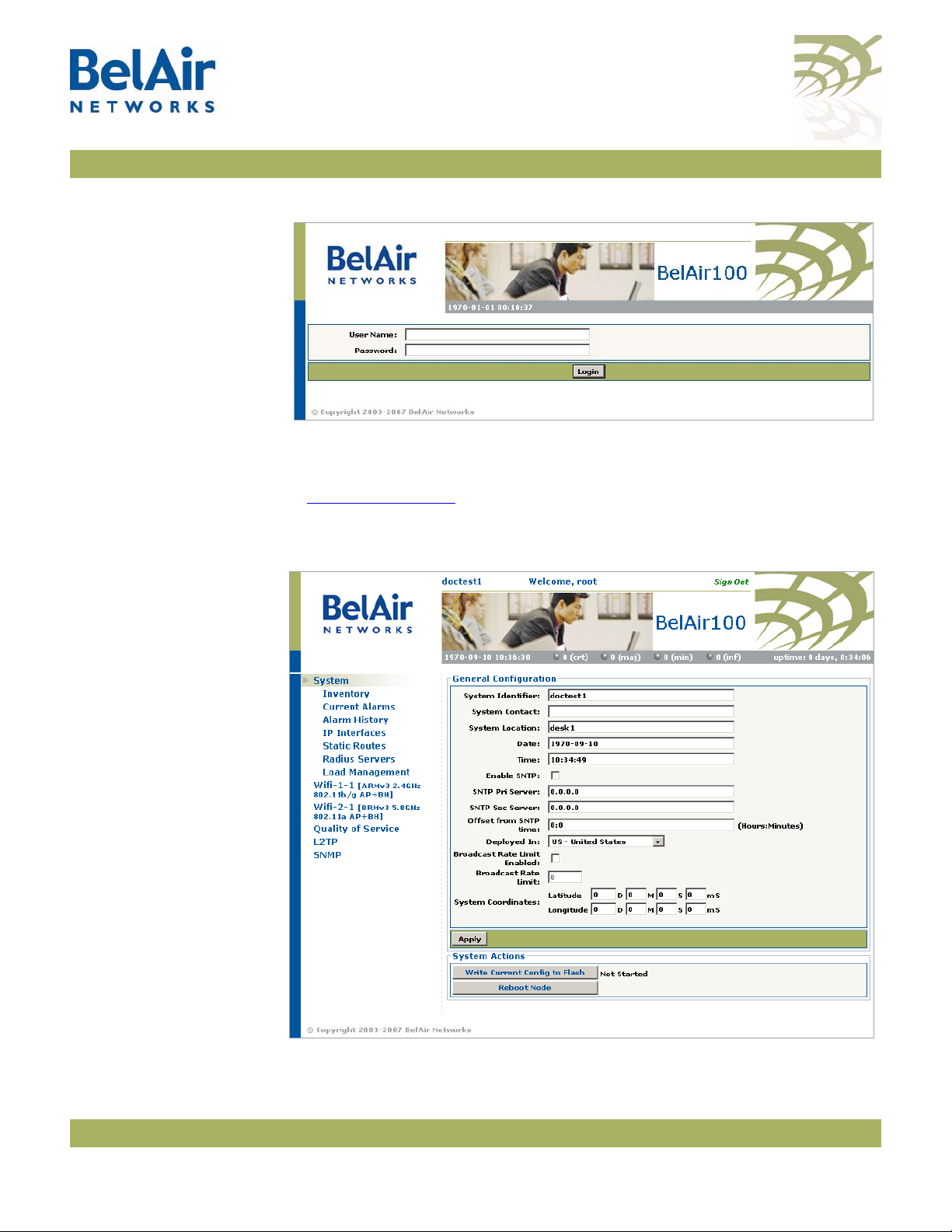
1 Open your Web browser and specify the IP address of the BelAir20E node
you want to access.
The default IP address of each BelAir20E node is: 10.1.1.10.
Figure 2 shows the resulting Login page.
April 2, 2012 Confidential Page 9 of 255
Document Number BDTM02201-A01 Standard
BelAir20E User Guide BelAir20E Configuration Interfaces
Figure 2: Typical Login Page
2 Enter a valid user name, such as root, and a valid password.
Note:The specified password is case sensitive.
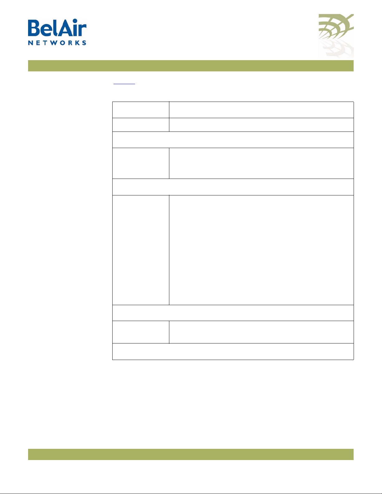
Figure 3 on page 10
interface.
Figure 3: Typical Web Interface Main Page
shows a typical resulting main page for the Web
April 2, 2012 Confidential Page 10 of 255
Document Number BDTM02201-A01 Standard

BelAir20E User Guide BelAir20E Configuration Interfaces
Stopping a Session To stop a Web interface session, click on the Logout button located in the top
right corner each page. See Figure 3.
Additional Troubleshooting Tools
The Web interface provides the following tools to display radio performance
metrics:
• a throughput meter
• histogram display of various performance metrics
These tools are only available with the Web interface. For full details, see the
BelAir20E Troubleshooting Guide
.
April 2, 2012 Confidential Page 11 of 255
Document Number BDTM02201-A01 Standard

BelAir20E User Guide Command Line Interface Basics
Command Line Interface Basics
Use this chapter to familiarize yourself with basic CLI tasks, including:
• “Connecting to the BelAir20E” on page 12
• “Starting a CLI Session” on page 12
• “Command Modes” on page 14
• “Abbreviating Commands ” on page 18
• “Command History” on page 18
• “Special CLI Keys ” on page 19
• “Help Command” on page 19
• “Common CLI Commands” on page 23
Connecting to the BelAir20E
CAUTION! Do not connect the BelAir20E to an operational data network before you
You can connect to the BelAir20E default address using one of the following
methods:
• through the BelAir20E radio interface
• by connecting directly to the Ethernet port on the BelAir20E
configure its desired IP network parameters. This may cause traffic disruptions
due to potentially duplicated IP addresses.
The BelAir20E unit must connect to an isolated LAN, or to a desktop or laptop
PC configured to communicate on the same IP sub-network as the BelAir20E.
Using the Radio Interface
Use a desktop or laptop PC equipped with a wireless 802.11a, 802.11b, 802.11g
or 802.11n compliant interface as required, configured with a static IP address
on the same subnet as the default OAM IP address (for example, 10.1.1.1/24).
For the required configuration procedure, refer to your PC and wireless
interface configuration manuals or contact your network administrator. The PC
will connect to the BelAir20E through the radio interface.
Connecting to the Ethernet Port
Use a cross-connect RJ45 cable to connect the Ethernet port of the unit.
For a detailed procedure, refer to the
BelAir20E Installation Guide
.
Starting a CLI Session
April 2, 2012 Confidential Page 12 of 255
Start a Telnet or secure shell (SSH) client and connect to the BelAir20E IP
address. If you are configuring the BelAir20E for the first time, you must use the
Document Number BDTM02201-A01 Standard

BelAir20E User Guide Command Line Interface Basics
BelAir20E default IP address (10.1.1.10). The BelAir20E prompts you for your
user name and password.
The default super-user account is “root”. The default password is “admin123”.
If the login is successful, the BelAir20E prompt is displayed. The default prompt
is “#”, if you login as root. Otherwise, the default prompt string is “>”.
Note 1: The terminal session locks after four unsuccessful login attempts. To
unlock the terminal session, you must enter the super-user password.
Note 2: BelAir20E CLI commands are not case sensitive (uppercase and
lowercase characters are equivalent). However, some command
parameters are case sensitive. For example, passwords and any Service
Set Identifier (SSID) supplied with the
sensitive. Also, all parameters of the
sensitive.
Note 3: Later, you will see that you can configure the BelAir20E to have more
than one interface with an IP address. For example, you can configure
Virtual LANs and management interfaces each with their own IP
address. If you do this, make sure your Telnet or secure shell (SSH)
connections are to a management interface. This ensures maximum
responsiveness for your session by keeping higher priority management
IP traffic separate from other IP traffic.
radio
syscmd
commands are case
commands are case
April 2, 2012 Confidential Page 13 of 255
Document Number BDTM02201-A01 Standard

BelAir20E User Guide Command Line Interface Basics
SSH Session Example of Initial Login
With secure shell, the system prompts you twice for your password.
ssh -l root 10.1.1.10
root@10.1.1.10's password:
BelAir Backhaul and Access Wireless Router
BelAir User: root
Password:
/#
Telnet Session Example of Initial Login
With Telnet, the system prompts you only once for your password.
telnet 10.1.1.10
BelAir Backhaul and Access Wireless Router
BelAir User: root
Password:
/#
Command Modes
The BelAir20E CLI has different configuration “modes”. Different commands
are available to you, depending on the selected mode.
Each card in the BelAir20E has at least one associated physical interface. Some
examples of physical interfaces are a Wi-Fi radio or an Ethernet interface.
Use the
mode
command to display the modes that are available. Because each
physical interface and each card in the BelAir20E has its own mode, displaying
the modes also displays a profile summary of the BelAir20E. See Figure 4.
April 2, 2012 Confidential Page 14 of 255
Document Number BDTM02201-A01 Standard

BelAir20E User Guide Command Line Interface Basics
/# mode
/card
/htme-1
/interface
/wifi-1-1 (HTMEv1 5GHz 802.11n)
/wifi-1-2 (HTMEv1 2.4GHz 802.11n)
/eth-1-1 (1000BASE-T)
/lan-1 (1000BASE-T)
/lan-2 (1000BASE-T)
/lan-3 (1000BASE-T)
/lan-4 (1000BASE-T)
/mgmt
/protocol
/ip
/nat
/radius
/rstp
/snmp
/sntp
/te-syst (tunnel)
/qos
/services
/auto-conn
/mobility
/ssh
/ssl
/syslog
/system
/diagnostics
• The node has one card. The HTME
card is in slot 1.
• The node has the following physical
interfaces:
—Interface
wifi-1-1
is associated
with the HTME 5.8 GHz radio.
—Interface
wifi-1-2
is associated
with the HTME 2.4 GHz radio.
—Interface
eth-1-1
is associated with
the HTME card’s Ethernet
interface.
—Interfaces
lan-1
to
lan-4
are
associated with the HTME card’s
LAN interfaces.
• The
mgmt
mode allows you to
control user accounts, which
authentication to use, and whether
you can access the node with Telnet.
• You can control the IP, RADIUS,
RSTP, SNMP, SNTP, L2TP and NAT
protocols through the
protocol
mode and its submodes.
• You can control auto-connect and
backhaul mobility through the
services
mode and its submodes.
• These modes allow you to control
SSH, SSL, Syslog and system settings.
You can also run diagnostics.
Figure 4: Sample Output of mode Command
April 2, 2012 Confidential Page 15 of 255
Document Number BDTM02201-A01 Standard
BelAir20E User Guide Command Line Interface Basics
Ta bl e 4
Table 4: Command Line Interface Modes
describes the modes that are supported.
Mode Description
“root” mode (/) The top or root level of the CLI commands.
Card Management: /card/<card_type>-<n>
one of:
•htme-<n>
Physical Interfaces: /interface/<iface>-<n>-<m>
one of:
• wifi-<n>-<m>
• eth-<n>-<m>
•lan-<n>
Configure hardware:
•
htme
is High Throughput Module, evolved
•<n> is slot number
Configure the BelAir20E physical interfaces:
• <iface> is the type of physical interface. One of:
—
wifi
: 802.11a/b/g/n, HTME radios
—
eth
: 1000Base-TX, HTME Ethernet
—
lan
: 1000Base-TX, HTME LAN
•<n> is the slot number where the interface is located
in the BelAir platform
• <m> is port number. <m> is 1 for most interfaces.
The HTME card can have multiple ports representing
multiple Wi-Fi radios operating different frequencies.
Some configurations may have multiple Ethernet or
LAN ports.
Node Management
mgmt • Configure user accounts, user authentication and
Te l n e t a c c e s s
Protocol Management: /protocol/<protocol>
April 2, 2012 Confidential Page 16 of 255
Document Number BDTM02201-A01 Standard

BelAir20E User Guide Command Line Interface Basics
Table 4: Command Line Interface Modes (Continued)
Mode Description
one of:
•ip
•nat
•radius
•rstp
• snmp
• sntp
• te-<eng>
Configure the following protocols:
• IP parameters for node and VLANs
•NAT
• RADIUS for user sessions
•RSTP
• SNMP
•SNTP
• L2TP tunnel engine (te). BelAir platforms can have one
tunnel engine per system (syst).
Services: /services/<service>
one of:
• auto-conn
• mobility
Configure the following services:
• Auto-configuration
•Backhaul mobility
Administration
qos Configure Quality of Service (QoS) parameters
ssh Configure Secure Shell (SSH) parameters
ssl Configure Secure Socket Layer (SSL) parameters
syslog Configure the destination of SYSLOG messages
See the
BelAir20E Troubleshooting Guide
for details.
system System and node configuration and administration
diagnostics Run link diagnostics.
You can move between modes with the cd command. For instance, you can
move from
/# cd /system
/system#
root
mode to
system
mode using the command:
April 2, 2012 Confidential Page 17 of 255
Document Number BDTM02201-A01 Standard

BelAir20E User Guide Command Line Interface Basics
Note 1: The prompt changes to match the current mode. You can further
customize the prompt to show the switch name or a 20-character
string that you define.
Note 2: Access to a mode is only allowed if the user has sufficient privileges to
execute commands in that mode.
When you access a given mode, only the commands pertaining to that mode
are available. For example, accessing
snmp
mode provides access to SNMP
commands. For a physical interface, this means that only the commands that
apply to that specific type and version of interface are available when you access
a particular physical interface. For example, if you access an HTMEv1 interface,
only the commands that apply to an HTMEv1 Wi-Fi radio are available.
Entering ? displays the commands that apply to the currently accessed mode.
Entering ?? or
help
displays the commands that apply to the currently accessed
mode plus common commands that are available in all modes.
Users may execute commands from other modes than the current one, by
prefixing the desired command with the slash character ‘/’ followed by the
mode’s name. For instance, entering:
Abbreviating Commands
Command History
/system# /protocol/snmp/show community
executes a command from
snmp
mode while in
system
mode.
You must enter only enough characters for the CLI to recognize the command
as unique.
The following example shows how to enter the
telnet status
/mgmt# sh t s
You can use the
:
history
command to display a list of the last commands that
mgmt
mode command
show
you have typed.
Example
/# history
8 h
9 hi
10 ?
11 show user
12 cd /system
13 show loads
14 show sessions
15 cd /
April 2, 2012 Confidential Page 18 of 255
Document Number BDTM02201-A01 Standard

BelAir20E User Guide Command Line Interface Basics
16 cd interface/wifi-1-1/
17 ?
18 show
19 show ssid table
20 show statistics
21 history
Special CLI Keys Command Completion
You can ask the CLI to complete a partially typed command or mode name by
pressing the
unambiguously, the CLI presents you with a list of possible completions. For
instance, entering:
/system# show co{tab}
produces the following output:
Available commands :
show communications
show config-download status
show coordinates
show country [detail]
Execution of the Last Typed Command
tab
key. If the command or mode name cannot be completed
Help Command ?
You may repeat the last command, by entering the ! key twice, followed by
carriage return.
Executing the Previous Commands
You may browse through the command history by using the up and down arrow
keys of a VT100 or compatible terminal. You can also execute a certain
command from the command history by entering the ! key, followed by the
command number (as displayed in the
history
command output) and carriage
return.
?? [<command>]
help [<command>]
These commands display:
• a list of commands available in the current mode
• help on a particular command available in the current mode
• help on commands starting with the given keyword in the current mode
Entering "??" is equivalent to entering "help".
April 2, 2012 Confidential Page 19 of 255
Document Number BDTM02201-A01 Standard

BelAir20E User Guide Command Line Interface Basics
Available Commands
Entering
?
displays the commands that apply to the currently accessed mode.
For example:
/mgmt# ?
Available commands :
adduser <user-name> -p <passwd> [ -d <default-mode>] [-g <grp-name>]
deluser <user-name>
moduser <user-name> [ -p <passwd>] [ -d <default-mode>] [-g <grp-name>]
set authentication-login {local | radius <list>}
set telnet {enabled|disabled}
show authentication-login
show telnet status
show user
Entering ?? or
help
displays the commands that apply to the currently accessed
mode plus common commands that are available in all modes. For example:
/mgmt# ??
Available commands :
adduser <user-name> -p <passwd> [ -d <default-mode>] [-g <grp-name>]
deluser <user-name>
moduser <user-name> [ -p <passwd>] [ -d <default-mode>] [-g <grp-name>]
set authentication-login {local | radius <list>}
set telnet {enabled|disabled}
show authentication-login
show telnet status
show user
alias [<replacement string> <token to be replaced>]
cd <path>
clear-screen
console lock
exit
help [ command ]
history
mode [<mode_name>]
passwd
ping <ip addr> [-l <size>]
run script <script file> [<output file>]
version
whoami
config-save [{active|backup} remoteip <server> remotefile <filename>
[{tftp | ftp [user <username> password <password>]}]]
config-restore remoteip <ipaddress> remotefile <filename> [{tftp | ftp
[user <username> password <password>]}] [force]
show date
su <username>
Keyword Help
Entering ?? or
help
followed by a keyword displays all possible commands
starting with that keyword. For example:
/mgmt# ?? show
Available commands :
April 2, 2012 Confidential Page 20 of 255
Document Number BDTM02201-A01 Standard

BelAir20E User Guide Command Line Interface Basics
show authentication-login
Description : show authentication login status and RADIUS servers
configuration
show telnet status
Description : shows the status of the telnet.
show user
Description : List all valid users, along with their permissible mode.
show date
Description : show current system date and time
Help for a Specific Command
When help is needed for a specific command, enter ?? or
help
followed by the
command within quotes. For example:
/mgmt# help "adduser"
Available commands :
adduser <user-name> -p <passwd> [ -d <default-mode>] [-g <grp-name>]
Description : Create a user.
Help with Abbreviations
When an abbreviation is used in the help string, all matching commands are
listed with the description. For example:
/mgmt# ?? s
Available commands :
set authentication-login {local | radius <list>}
Description : defines how login session will be authenticated.
set telnet {enabled|disabled}
Description : enable or disable CLI access via the telnet protocol.
show authentication-login
Description : show authentication login status and RADIUS servers
configuration
show telnet status
Description : shows the status of the telnet.
show user
Description : List all valid users, along with their permissible mode.
show date
Description : show current system date and time
su <username>
Description : Substitute present user with the given user.
Saving your Changes
If you change any settings from the system defaults, you must save those
changes to the configuration database to make sure they are applied the next
time the BelAir20E reboots. Similarly, you can restore the entire configuration
database from a previously saved backup copy.
Saving the Configuration Database
config-save [{active|backup} remoteip <ipaddress>
remotefile <filename>
[{tftp|ftp [user <usrname> password <pword>]}]]
This command allows you to save the current configuration of the entire
BelAir20E node. This includes all system, layer 2 and radio settings.
April 2, 2012 Confidential Page 21 of 255
Document Number BDTM02201-A01 Standard

BelAir20E User Guide Command Line Interface Basics
Restoring the Configuration Database
When used without its optional parameters, the
the configuration database for the active software load to persistent storage.
The stored configuration is automatically applied at the next reboot.
When used with its optional parameters, the
transfers the configuration database to a remote server.
If
active
is specified, the
for the active software load to persistent storage and then transfers it to a
remote server. If
software load is not saved. Instead, the configuration database for the active
software load that was saved previously to persistent storage, is transferred to
a remote server.
You can use either TFTP or FTP to communicate with the remote server. By
default, the
specify the username and password. The default FTP username is
and the default FTP password is
address of node making the request. If you do not use the default FTP
username, the FTP server must be configured to accept your username and
password.
config-restore remoteip <ipaddress> remotefile <filename>
[{tftp|ftp [user <usrname> password <pword>]}]]
[force]
This command transfers the configuration database from a remote server to
the active software load in persistent storage. This allows you to restore the
entire configuration database from a previously saved backup copy.
backup
config-save
config-save
is specified, the configuration database for the active
command uses TFTP. If you specify FTP, you can also
command saves the configuration database
root@<nodeip>
config-save
config-save
command saves
command also
anonymous
, where <nodeip> is the IP
Use the
You can use either TFTP or FTP to communicate with the remote server. By
default, the
specify the user name and password. The default FTP user name is
and the default FTP password is
address of node making the request. If you do not use the default FTP
username, the FTP server must be configured to accept your username and
password.
The optional
file that is being downloaded. You can use a backup copy that was created with
a different version of software than the current software installed on the unit. If
you do, BelAir Networks strongly recommends that you fully and thoroughly
verify the configuration and operation of the unit after you reboot the system
and before you save the restored configuration.
April 2, 2012 Confidential Page 22 of 255
Document Number BDTM02201-A01 Standard
reboot
command for the new configuration to take effect.
config-restore
force
command uses TFTP. If you specify FTP, you can also
anonymous
root@<nodeip>
parameter suppresses version checking on the configuration
, where <nodeip> is the IP

BelAir20E User Guide Command Line Interface Basics
Example
/# cd system
/system# config-restore remoteip 122.45.6.123 remotefile unitA.conf
Common CLI Commands
Terminating your CLI Session
Changing Your Password
CAUTION! If you forget the super-user account password, you may be unable to use all the
In addition to any previously described commands, the following commands are
always available, regardless of your current mode.
exit
Use this command to terminate your own CLI session at any time.
passwd
This command lets you change your current password. First, you are asked to
enter your old password. Then you must enter your new password twice, to
verify that you have typed it correctly.
Note: The specified password is case sensitive, must consist of alphanumeric
characters, must be at least six characters long, and cannot exceed 20
characters.
unit’s management functions and you may need to reset the unit’s configuration
to factory defaults.
Example
passwd
Old Password:
Enter New Password:
Reenter the Password:
Password updated Successfully
Clearing the Console Display
Locking the Console Display
clear-screen
This command clears your console display window.
console lock
This command lock your console display window. You must enter your
password to unlock it.
Displaying the Current Software Version
version
This command displays the version of the currently running BelAir software
load.
Example
/# version
April 2, 2012 Confidential Page 23 of 255
Document Number BDTM02201-A01 Standard

BelAir20E User Guide Command Line Interface Basics
Version is BA20E 12.0.0.D.2011.01.19.14.32 (r36096)
Displaying the Current Date and Time
Displaying Current User
show date
This command displays the current date and time.
Example 1
The following example displays the current date and time when it is set
manually.
/# show date
Current date: 2007-05-10 06:52:20
Example 2
The following example displays the current date and time when using a Simple
Network Time Protocol (SNTP) server and a time offset of -4 hours and 30
minutes. See “Configuring the System Date and Time” on page 51 for details.
/# show date
Current date: 2006-07-21 13:15:16 (UTC)
Current date: 2006-07-21 08:45:16
whoami
This command displays current user.
Example
/# whoami
/# Current User is root
Switching User Accounts
su <username>
This command changes the user account you are currently using. To return to
exit
the original user account, use the
command.
Example
/# whoami
Current User is root
/# su guest
/> whoami
Current User is guest
/> exit
/# whoami
Current User is root
Replacing a Token by a String
alias [<replacement string> <token to be replaced>]
This command replaces the specified token by the given string. It is provided for
customers writing scripts. See “Scripting Guidelines” on page 223.
April 2, 2012 Confidential Page 24 of 255
Document Number BDTM02201-A01 Standard

BelAir20E User Guide Command Line Interface Basics
Example
/# alias gu guest
Pinging a Host or Switch
Starting a Telnet Session
ping <host> [-1 <size>]
This command pings a host machine or switch using the host name or IP
address.
The following options are supported:
-l size
specifies the size of the ping request packets to be sent.
Examples
The following example shows typical ping output:
/# ping 10.1.1.100 -l 128
PING 10.1.1.100 (10.1.1.100): 128 data bytes
136 bytes from 10.1.1.100: icmp_seq=0 ttl=128 time=2.0 ms
136 bytes from 10.1.1.100: icmp_seq=1 ttl=128 time=1.2 ms
136 bytes from 10.1.1.100: icmp_seq=2 ttl=128 time=1.0 ms
--- 10.1.1.100 ping statistics --3 packets transmitted, 3 packets received, 0% packet loss
round-trip min/avg/max = 1.0/1.4/2.0 ms
telnet <ip address> [<port_number>]
This command lets you start a Telnet session to another machine, such as
another BelAir node, by specifying the IP address. By default t, Telnet uses
port 23. You can also specify an alternate port number.
Radio Configuration Summary
show interface summary
This command displays a summary of the configuration of all radio interfaces.
Example
The following example shows a typical output for a BelAir20.
/# show interface summary
wifi-1-1
Radio description:............ HTMv1 5GHz 802.11n
Admin state: ................. Enabled
Channel: ..................... 149
Access:
AP admin state: ............ Enabled
Backhaul:
link admin state: .......... Enabled
link id: ................... BelAirNetworks
topology: .................. mesh
wifi-1-2
Radio description:............ HTMv1 2.4GHz 802.11n
Admin state: ................. Enabled
Channel: ..................... 6
April 2, 2012 Confidential Page 25 of 255
Document Number BDTM02201-A01 Standard

BelAir20E User Guide Command Line Interface Basics
Access:
AP admin state: ............ Enabled
Backhaul:
link admin state: .......... Disabled
link id: ................... BelAirNetworks
topology: .................. mesh
April 2, 2012 Confidential Page 26 of 255
Document Number BDTM02201-A01 Standard

BelAir20E User Guide BelAir20E Access Methods
BelAir20E Access Methods
When a BelAir20E is shipped from the factory, all access methods (CLI, SNMP,
Telnet, HTTP, HTTPS, SSH) are enabled. You can use these interfaces to
configure the system’s IP networking parameters.
This chapter describes the CLI commands you can use to configure these
access methods.
Note: Some access methods, such as HTTP and HTTPS, are configured while
in SSL mode.
SNMP
Configuration
This section describes how to configure the BelAir20E to communicate to
either an SNMPv1/v2 server or an SNMPv3 server.
Guidelines
SNMPv1/v2 Servers To configure an SNMP community, use the
in “Communities” on page 29.
For sending traps, use the
to configure the node with the parameters of the destination SNMP manager.
Refer to “SNMP Command Reference” on page 28 for detailed descriptions of
all SNMP commands.
SNMPv3 Servers To configure an SNMP user, use the
page 30.
For sending notifications, use the
“Notifications” on page 30 to configure the node with the parameters of the
destination SNMP manager.
Refer to “SNMP Command Reference” on page 28 for detailed descriptions of
all SNMP commands, including entities that need to be predefined.
SNMP Naming Restrictions
SNMP community names, user names, and notification names must not contain
the following characters:
set trap
command described in “Traps” on page 29
set user
set notify
set community
command described in “Users” on
command described in
command described
—bar (|)
—semicolon (;)
—percent (%)
—double quotation mark (“)
April 2, 2012 Confidential Page 27 of 255
Document Number BDTM02201-A01 Standard

BelAir20E User Guide BelAir20E Access Methods
SNMP Command
The following sections show you how to configure SNMP functions.
Reference
SNMP Agent
SNMP Configuration
EngineId: 80003d9805000d67091448
Community configuration:
-----------------------Index Name IP Address Privilege
----- ------------------ --------------- ----------1 public 0.0.0.0 ReadOnly
2 private 10.1.1.70 ReadWrite
Trap configuration:
------------------Index IP address Community Version
----- --------------- --------------- ------1 10.1.1.70 public v1v2
/protocol/snmp/set snmp-agent {enabled | disabled}
/protocol/snmp/show snmp-agent
The
set snmp-agent
/protocol/snmp/show config [{v2 | v3 | all}]
Use the
Passwords are only displayed to users with
show config
command enables or disables SNMP access.
command to display the current SNMP configuration.
root
privileges. See “User Privilege
Levels” on page 35 for details.
Example 1
/protocol/snmp# show config v2
Example 2
/protocol/snmp# show config v3
EngineId: 80003d9805000d67006902
User configuration:
------------------User Name IP address Auth Password Privacy Password Privilege
------------------------- --------------- ---- --------------- -------- --------------- --------Test 0.0.0.0 MD5 md5md5md5 DES_CBC TEST ReadWrite
Notification configuration:
------------------Name Type IP address Timeout Retry Auth Password Privacy Password
--------------- ------ --------------- ------- ----- ---- --------------- ------- --------TRAP trap 10.1.1.70 1250 2 MD5 md5md5md5 DES_CBC TRAP
April 2, 2012 Confidential Page 28 of 255
Document Number BDTM02201-A01 Standard

BelAir20E User Guide BelAir20E Access Methods
Communities
/protocol/snmp/set community <CommunityIndex>
community-name <name> ipaddr <ip_addr>
privilege {readonly|readwrite}
/protocol/snmp/delete community <CommunityIndex>
/protocol/snmp/show community
The
set community
command configures the SNMP community security. You
can configure up to 10 communities. The community is assigned with privileges.
The
delete community
The
show
command displays the SNMP community configuration.
command deletes the specific community information.
Assigning an IP address of 0.0.0.0 to an SNMP community of a node allows node
access by all managers configured for that community. See “Example 1” on
page 29. To limit access to a single manager, enter the manager’s IP address. See
“Example 2” on page 29.
Example 1
/protocol/snmp# set community 1 community-name belair ipaddr 0.0.0.0 privilege readonly
In this example, all managers configured with the SNMP community of
belair
can access the node for read only functions.
Example 2
/protocol/snmp# set community 1 community-name belair200 ipaddr 10.10.10.11 privilege readonly
/protocol/snmp# set community 2 community-name belair100 ipaddr 20.20.20.20 privilege readwrite
/protocol/snmp# set community 3 community-name belcom ipaddr 30.30.30.30 privilege readonly
In the previous example, the manager at IP address 20.20.20.20 configured with
the SNMP community of
belair100
has read-write access to the node.
Example 3
/protocol/snmp# show community
Index Name IP Address Privilege
----- ------------------ --------------- ----------1 public 0.0.0.0 ReadOnly
2 private 10.1.1.70 ReadWrite
Tr ap s
/protocol/snmp/set trap <index> mgr-addr <ip_addr>
community <name> version {v1|v2|both}
/protocol/snmp/delete trap <index>
/protocol/snmp/show trap
The
set trap
command configures the parameters of the SNMPv2 trap manager.
You can configure up to 10 traps.
delete trap
The
command deletes the specified trap manager information.
April 2, 2012 Confidential Page 29 of 255
Document Number BDTM02201-A01 Standard

BelAir20E User Guide BelAir20E Access Methods
The
show trap
command displays the SNMPv2 trap manager configuration
information.
Example 1
/protocol/snmp# set trap 1 mgr-addr 40.40.40.40 community bel1 version v1
/protocol/snmp# set trap 2 mgr-addr 41.41.41.41 community bel2 version v2
Example 2
/protocol/snmp# show trap
Index IP address Community Version
----- --------------- --------------- ------1 10.1.1.70 public v1v2
Users
/protocol/snmp/set user <UserName> ipaddr <IP_addr>
access {readonly | readwrite}
[auth {md5 | sha} <password> [priv-DES <passwd>]]
/protocol/snmp/delete user <UserName>
/protocol/snmp/show user
The
set user
command defines an SNMPv3 user. You can define up to 10 users,
each with different authentication and privacy settings.
The
ipaddr
access
The
<password>
parameter specifies the IP address associated with this user. The
parameter specifies the level of access granted to this user.
parameter is the password required by the user to access
SNMP data. A user must supply this password if using a MIB browser.
The BelAir20E uses DES encryption to encrypt SNMP packets. The
priv-DES
parameter specifies the encryption key required to encrypt or decrypt the
packet.
The
delete user
The
show
to users with
command deletes the definition of the specified SNMP user.
command displays the configured users. Passwords are only displayed
root
privileges. See “User Privilege Levels” on page 35 for details.
Example 1
/protocol/snmp# set user v3md5 ipaddr 0.0.0.0 access readwrite auth md5 md5md5md5
Example 2
/protocol/snmp# show user
User Name IP address Auth Password Privacy Password Privilege
-------------- --------------- ---- --------------- -------- --------v3md5 0.0.0.0 MD5 md5md5md5 None none ReadWrite
Notifications
/protocol/snmp/set notify <NotifyName> type {Trap | Inform}
ipaddr <IP_addr> [timeout <1-1500>]
April 2, 2012 Confidential Page 30 of 255
Document Number BDTM02201-A01 Standard

BelAir20E User Guide BelAir20E Access Methods
[retries <1-3>] [auth {md5 | sha}
<password> [priv-DES <passwd>]]
/protocol/snmp/delete notify <NotifyName>
/protocol/snmp/show notify
The
set notify
command enables notifications to be sent to an SNMPv3
manager for the specified notification name. You can configure up to
10 notification names.
The
ipaddr
The
timeout
acknowledgement before resending the SNMP packet. The
parameter specifies the IP address associated with this notification.
parameter specifies how many seconds to wait for an
retries
parameter
specifies the number of times to resend the SNMP before declaring a failure.
The
<password>
parameter is the password associated with this notification.
The BelAir20E uses DES encryption to encrypt SNMP packets. The
priv-DES
parameter specifies the encryption key required to encrypt or decrypt the
packet.
The
delete notify
command disables notifications from being sent for the
specified notification name.
The
show notify
Passwords are only displayed to users with
command displays the current SNMP notify configuration.
root
privileges. See “User Privilege
Levels” on page 35 for details.
Example 1
/protocol/snmp# set notify trap1 type trap ipaddr 10.1.1.70
Example 2
Name Type IP address Timeout Retry Auth Password Privacy Password
--------------- ------ -------------- ------- ----- ---- --------------- ------- ------------trap1 trap 10.1.1.70 1500 3 None none None none
trap2 trap 10.1.1.70 1250 3 None none None none
trap3 trap 10.1.1.70 1250 2 None none None none
trap4 trap 10.1.1.69 1500 3 SHA shasha None none
trap5 trap 10.1.1.69 1500 3 MD5 md5md5 None none
trap6 trap 10.1.1.11 1500 3 None none None none
trap7 trap 10.1.1.12 1250 3 None none None none
trap8 trap 10.1.1.12 1250 3 MD5 md5md5 DES_CBC JEKTEST
trap9 trap 10.1.1.9 1250 3 MD5 md5md5 DES_CBC bob
trap10 trap 10.1.1.8 50 1 MD5 md5md5 DES_CBC bob
/protocol/snmp# show notify
Authentication Traps
/protocol/snmp/set authentication-trap {enable|disable}
/protocol/snmp/show authentication-trap status
These commands enable or disable the ability to send authentication traps.
April 2, 2012 Confidential Page 31 of 255
Document Number BDTM02201-A01 Standard

BelAir20E User Guide BelAir20E Access Methods
Engine Identifier
Te l n e t
HTTP
/protocol/snmp/show engineid
This command displays the current engine identifier.
/mgmt/telnet {enable|disable}
/mgmt/show telnet status
The
telnet
command enables or disables Telnet access to the unit.
The
show
command displays the status of the Telnet interface.
Example 1
/#cd /mgmt/
/mgmt# telnet enable
Example 2
cd /mgmt/
/mgmt# show telnet status
Telnet: Enabled
/ssl/set http {enable|disable}
/ssl/show http status
These commands enable or display the HTTP interface. The
displays the current status.
show
command
Secure HTTP
SSH
SSH Access
SSL
Displaying Server Certificate
/ssl/set secure-http {enable|disable}
/ssl/show secure-http status
These commands enable or display the secure HTTP interface. The
show
command displays the current status.
The following sections show you how to configure the Secure Shell (SSH)
functions.
/ssh/show ssh status
This command displays the status of the SSH interface.
The following sections show you how to configure the Secure Socket Layer
(SSL) functions.
/show ssl server-cert
This command displays the server-certificate for SSL.
April 2, 2012 Confidential Page 32 of 255
Document Number BDTM02201-A01 Standard

BelAir20E User Guide BelAir20E Access Methods
Configuring the Server Certificate
Creating RSA Key Pair
Creating Certificate Request
To configure the server certificate:
1 Create the RSA key pair. See “Creating RSA Key Pair” on page 33
.
2 Create a certificate request. See “Creating Certificate Request” on page 33.
The certificate request is displayed on the screen.
3 Copy the certificate request to a file and send it to the Certificate Authority
(CA) that will generate the certificate.
4 When the CA responds with the certificate, configure the BelAir20E SSL
configuration to use it. See “Configuring the Server Certificate” on page 33.
5 Save the SSL configuration. See “Saving an SSL Configuration” on page 33.
/ssl/ssl gen key {rsa} <no. of bits>
This command creates a new RSA key pair. The input value of
no of bits
can be
512 or 1024.
Example
/#cd ssl
/ssl# ssl gen key rsa 1024
/ssl/ssl gen cert-req algo rsa sn <SubjectName>
This command creates a certificate request using the RSA key pair and
SubjectName
. The subject name is the identification of the switch or the
switch’s IP address.
Example
/#cd ssl
/ssl# ssl gen cert-req algo rsa sn 10.1.1.10
Configuring the Server
/ssl/ssl server-cert
Certificate
This command imports a server certificate provided by a CA.
When you use this command, you are prompted to enter the certificate. To do
so, open the certificate and copy its contents to the CLI.
Note: The application that you use to open the certificate may insert
additional line breaks and spaces at the end of each line of the
certificate. Make sure to remove these extra line breaks and spaces
when you copy the certificate to the CLI.
Saving an SSL
/ssl/ssl save
Configuration
This command saves the SSL configuration.
April 2, 2012 Confidential Page 33 of 255
Document Number BDTM02201-A01 Standard

BelAir20E User Guide BelAir20E Access Methods
Example
/#cd ssl
/ssl# ssl save
April 2, 2012 Confidential Page 34 of 255
Document Number BDTM02201-A01 Standard

BelAir20E User Guide User and Session Administration
User and Session Administration
This chapter describes user administration functions with the following topics:
• “User Privilege Levels” on page 35
• “User Accounts” on page 38
• “Configuring Authentication for User Accounts” on page 39
• “CLI and Web Sessions” on page 41
User Privilege Levels
User accounts on the BelAir20E can be assigned the following three privilege
levels:
•An
•A
• The
Each unit can have any number of observer users and normal users, but only
one super-user account, called
observer
—most
—the
—the
—the
—the cd and
—the
—the
—the
normal
the super-user.
super-user
CLI commands that are reserved for the super-user.
user can execute only the following commands:
show
commands
help
and ? commands
passwd
clear-screen
history
whoami
ping
command
and
exit
commands
mode
commands
command
command
command
user can execute any CLI command, except those reserved for
can execute any CLI command. Table 5 on page 35 lists the
root
.
Table 5: Super-user commands
Common Commands
config-restore remoteip <ipaddress> remotefile <filename>
[{tftp|ftp [user <usrname> password <pword>]}]]
[force]
April 2, 2012 Confidential Page 35 of 255
Document Number BDTM02201-A01 Standard

BelAir20E User Guide User and Session Administration
Table 5: Super-user commands (Continued)
Mgmt Commands
adduser <user-name> -p <passwd> [-d <mode>] [-g <group>]
deluser <user-name>
moduser <user-name> [ -p <passwd>] [ -d <mode>] [-g <group>]
show user
set telnet {enabled|disabled}
set authentication-login {local | radius <list>}
show authentication-login
System Commands
set country <country_name>
set global-session-timeout <period>
terminate session <session_index>
upgrade load remoteip <serverIPaddress>
remotepath <serverSubDir>
[{tftp|ftp [user <usrname> password <pword>]}]]
cancel upgrade
reboot [{force}]
commit load
set next-load {A|B|current|inactive}
syscmd restoreDefaultConfig
/Card/<card_type>-n Commands
reboot [{force}]
/Protocol/IP Commands
set interface {system | vlan <1-2814>}
static <ip addr> <mask>
[delay-activation]
set interface {system | vlan <1-2814>} dynamic
fallback-ip <address> <mask>
accept-dhcp-params {enabled|disabled}
[delay-activation]
April 2, 2012 Confidential Page 36 of 255
Document Number BDTM02201-A01 Standard

BelAir20E User Guide User and Session Administration
Table 5: Super-user commands (Continued)
renew ip {system | vlan <1-2814>}
SSL Mode Commands
set http {enable|disable}
set secure-http {enable|disable}
show http status
show secure-http status
show server-cert
ssl gen cert-req algo rsa sn <SubjectName>
ssl gen key {rsa} <no. of bits>
ssl save
ssl server-cert
Syslog Mode Commands
logserver {enable [<ip address>] | disable}
monitor logging {enable | disable}
loglevel {debug|info|notice|warn|error|critical|alert|emerg}
/Protocol/SNMP Mode Commands
set snmp-agent {enabled | disabled}
set community <CommunityIndex>
community-name <name> ipaddr <ip_addr>
privilege {readonly|readwrite}
delete community <CommunityIndex>
set trap <index> mgr-addr <ip_addr>
community <name> version {v1|v2|both}
delete trap <index>
set user <UserName> ipaddr <IP_addr>
access {readonly | readwrite}
[auth {md5 | sha} <password> [priv-DES <passwd>]]
delete user <UserName>
April 2, 2012 Confidential Page 37 of 255
Document Number BDTM02201-A01 Standard

BelAir20E User Guide User and Session Administration
Table 5: Super-user commands (Continued)
set notify <NotifyName> type {Trap | Inform}
ipaddr <IP_addr> [timeout <1-1500>]
[retries <1-3>] [auth {md5 | sha}
<password> [priv-DES <passwd>]]
delete notify <NotifyName>
set authentication-trap {enable | disable}
User Accounts
/mgmt/adduser <user-name> -p <passwd> [-d <mode>] [-g <group>]
/mgmt/deluser <user-name>
/mgmt/moduser <user-name> [-p <passwd>] [-d <mode>] [-g <group>]
/mgmt/show user
The
The
adduser
deluser
command creates a new user account.
command deletes a user account. The default login, “root”, cannot
be deleted.
The
moduser
command, the
The
show user
command modifies the parameters of a user account. For this
group
parameter does not apply to changes to the
root
account.
command lists all valid user accounts, the mode in which they
start their session and their maximum privilege level. For example, under
Groups,
displays
The
normal users display
root NORMAL OBSERVER
mode
parameter sets the command mode that a user accesses when they
NORMAL OBSERVER
.
while the
root
account
log in. If unspecified, it defaults to a slash (/) so the user begins their session in
root mode. Users with observer privileges must start their sessions in root
mode.
group
The
OBSERVER
parameter specifies the user account’s privilege level. It can be
or
NORMAL
. If unspecified, the user account has observer
privileges.
To use this command, you must be in
mgmt
mode.
Note 1: The specified password is case sensitive, must consist of alphanumeric
characters, must be at least six characters long, and cannot exceed 20
characters. Changes the super-user account require that you provide
the super-user password.
Note 2: The specified group is case sensitive.
If you use a RADIUS server to authenticate users as they login, you must
specify the user’s privilege level in the RADIUS
Reply-Message
field. Specifically,
April 2, 2012 Confidential Page 38 of 255
Document Number BDTM02201-A01 Standard

BelAir20E User Guide User and Session Administration
the
Reply-Message
NORMAL
sure the user privilege levels are entered exactly as specified. If the privilege
levels are unspecified in RADIUS, then the BelAir20E provides the user with
observer
Example 1
/mgmt# adduser testuser -p userpwd - d system
Example 2
/mgmt# deluser xyz
Example 3
or
privileges.
field must contain in plain text one of the following:
OBSERVER
. These entries in RADIUS are case sensitive, so make
root
,
Configuring Authentication for User Accounts
Authentication Mode
In the following example, the user
and their password is changed to “guest123”.
/mgmt# moduser guest –p guest123 –d interface
Example 4
/mgmt# show user
USER MODE GROUPS
root / root NORMAL OBSERVER
user1 / OBSERVER
user2 / OBSERVER
user3 interface NORMAL OBSERVER
You can use a RADIUS server to authenticate users as they login to their
accounts. This applies to all user accounts including
/mgmt/set authentication-login {local|radius <list>}
/mgmt/show authentication-login
These commands determine how the BelAir20E authenticates users.
The
local
setting means that the BelAir20E uses the locally stored password and
user account information to authenticate the user. This is the default setting.
guest
begins their session in
root
interface
.
mode
radius
The
authenticate the user. The
RADIUS server list. Refer to “RADIUS Servers” on page 40
April 2, 2012 Confidential Page 39 of 255
Document Number BDTM02201-A01 Standard
setting means that the BelAir20E uses a RADIUS server to
list
parameter specifies the index used in the
.

BelAir20E User Guide User and Session Administration
Example 1
/mgmt# set authentication-login radius 1,2
Example 2
mgmt# show authentication-login
Authentication Login is radius
Radius Authentication server table
------------------------------------ Index : 1
Radius Server Address : 10.1.3.254
UDP port number : 1812
Radius Client Address : 10.1.3.48
Timeout : 3
------------------------------------------- Index : 2
Radius Server Address : 10.1.3.253
UDP port number : 1812
Radius Client Address : 10.1.3.48
Timeout : 3
--------------------------------------------
RADIUS Servers
/protocol/radius/set server <server-idx> <IP_addr>
<shared-secret>
[authport <server-port>]
[acctport <acct-port>]
[interface {system | vlan <1-2814>}]
[timeout <seconds>]
[reauthtime <seconds>]
/protocol/radius/set server-state <server-idx> {enabled|disabled}
/protocol/radius/del server <server-idx>
/protocol/radius/show servers
These commands allow you to specify a list of RADIUS servers that you can use
to authenticate users. The list can contain up to 10 servers.
IP_addr
The
The
shared-secret
parameter specifies the IP address of the RADIUS server.
parameter specifies the password for access to the RADIUS
server.
The
authport
parameter ranges from 0 to 65535. It specifies the UDP port
number of the RADIUS server (typically 1812).
The
acctport
parameter ranges from 0 to 65535. It specifies the UDP port
number for RADIUS accounting data (typically 1813).
The
interface
parameter specifies the interface to associate the BelAir20E
RADIUS client to. This can be the unit’s system interface or any VLAN
interface. The default value is
system
.
April 2, 2012 Confidential Page 40 of 255
Document Number BDTM02201-A01 Standard

BelAir20E User Guide User and Session Administration
The
timeout
parameter ranges from 2 to 300. It specifies the interval (in
seconds) after which the RADIUS client considers that the remote server has
timed out if a reply is not received. The default value is 10 seconds.
The
reauthtime
parameter ranges from 0 to 50000000. It specifies the RADIUS
re-authentication time (in seconds). This forces the BelAir20E to check all
connected clients with the RADIUS server (that is, make sure they are still
allowed to access the network) at the specified interval. You only need to
configure this parameter if it is not specified on the RADIUS server. Setting the
interval to zero disables this feature. The maximum interval time is
2147483647. If you enter a higher number, the value is set to its maximum.
Note: Make sure the user’s privilege level are correctly specified in the
RADIUS
Reply-Message
field. Refer to “User Accounts” on page 38.
Example 1
/protocol/radius# set server 3 172.16.1.20 my-secret12345 authport 1812 acctport 1813 interface
system timeout 15 reauthtime 1
Example 2
/protocol/radius# set server-state 3 enabled
CLI and Web Sessions
Session Management
The BelAir20E allows you to manage CLI and Web session, such as listing and
terminating sessions as well as configuring the idle timeout period.
/system/show sessions
/system/terminate session <session_index>
The
show sessions
command lists all active CLI and Web interface sessions.
The current session is flagged with an asterisk besides its session index number.
The
terminate session
command allows you to terminate any CLI or Web
session.
Example
/system# show sessions
index user type IP address since last-cmd timeout tssh logging
----- -------- ------- --------------- --------- --------- --------- --------- -------- 1 root telnet 10.9.9.14 0:27:57 0:01:43 0:30:00 inactive active
9 root telnet 10.9.9.14 0:22:09 0:00:00 0:30:00 inactive active
11[*] root web 10.9.9.14 0:13:51 0:13:51 1:00:00
In this example, the current session is session 11 with an idle period set at
1hour.
April 2, 2012 Confidential Page 41 of 255
Document Number BDTM02201-A01 Standard

BelAir20E User Guide User and Session Administration
Configuring the Session Timeout Interval
/system/set global-session-timeout <period>
/system/set session-timeout <period>
/system/show global-session-timeout
By default, a CLI session is automatically disconnected if it is idle for longer than
30 minutes. These commands allows you to change the idle period, preventing
unwanted disconnections. The idle period is specified in minutes. Setting a
period of 0 prevents any automatic disconnection.
The
set global-session-timeout
command changes the idle period of all CLI
sessions. Its <period> parameter ranges from 1 to 1440; that is up to 24 hours.
You cannot specify 0 as the global session idle period. You must be logged in as
root
to use this command.
The
set session-timeout
command changes the idle period of only the current
CLI sessions. Its <period> parameter ranges from 0 to 1440; that is up to
24 hours. The session timeout period overrides the global timeout period.
The new idle period takes effect immediately and to all current and future
sessions; until changed with these commands again.
The
show
command displays the settings for the global timeout period. To see
the setting for the session, use the
/system/show sessions
command.
CLI Prompt Customization
Example
/system# set idle-timeout 60
/system/set prompt selection [default|string|switch-name}
/system/set prompt string <20-char_string>
/system/show prompt
The
set prompt selection
command customizes the prompt for CLI sessions.
The choices are as follows:
•
default
•
switch-name
, where the CLI prompt includes the current command mode only
, where the CLI prompt includes the current command mode
and the first eight characters of the switch name described in “System
Identification Parameters” on page 50
•
string
, where the CLI prompt includes the current command mode and the
20-character string as defined by the
set prompt string
command. The string
can consist of any 20 ASCII characters, except for the semicolon (;).
The
show prompt
command displays the current prompt settings.
April 2, 2012 Confidential Page 42 of 255
Document Number BDTM02201-A01 Standard

BelAir20E User Guide User and Session Administration
Examples
/system#set prompt string BelAir-128-50-46-189
/system#set prompt selection string
[BelAir-128-50-46-189]/system#system
[BelAir-128-50-46-189]/system#set prompt selection switch-name
[BA20E-A]/system#set prompt selection switch-name
[BA20E-A]/system#set prompt selection default
/system# show prompt
User-defined string: BelAir-128-50-46-189
prompt selection: default
switch BA20E-A
April 2, 2012 Confidential Page 43 of 255
Document Number BDTM02201-A01 Standard

BelAir20E User Guide IP Settings
IP Settings
This chapter contains procedures for managing BelAir20E IP parameters as
follows:
• “Displaying IP Parameters” on page 44
• “Configuring IP Parameters” on page 45
—“Configuring Dynamic IP Addressing” on page 45
—“Renewing the IP Address” on page 46
—“Auto-IP” on page 46
—“Setting a Static IP Address and Subnet Mask” on page 47
—“Static IP Routes” on page 47
• “Configuring the Domain Name System Lookup Service” on page 48
• “Configuring IP Address Notification” on page 48
CAUTION! The BelAir20E uses internal IP addresses in the range of 192.168.1.x,
192.168.2.x and 192.168.3.x. As a result, do not configure the BelAir20E to use
any IP addresses within these ranges.
Displaying IP Parameters
/protocol/ip/show config
The
/protocol/ip/show config
command displays a detailed view of the system’s
IP configuration.
Example
Interfaces:
Address Configured/ Configured/ Accept
Current Current Alloc Fallback Fallback DHCP
Interface Address Netmask Type D Address Netmask Parameters
----------------------------------------------------------------------------------------------- System 10.9.9.20 255.255.255.0 Static 10.9.9.20 255.255.255.0 Disabled
AutoIP: Enabled
Routes:
Destination Netmask Gateway Interface Active
--------------- --------------- --------------- ------------------ ----- No static routes currently configured
DNS:
/protocol/ip# show config
April 2, 2012 Confidential Page 44 of 255
Document Number BDTM02201-A01 Standard

BelAir20E User Guide IP Settings
Domain name lookup: disabled
Configured domain name:
Configured primary DNS server: 0.0.0.0
Configured secondary DNS server: 0.0.0.0
Configuring IP Parameters
Configuring Dynamic IP Addressing
You can configure:
• dynamic IP addressing
• a static IP address and subnet mask, as well as static IP routes.
/protocol/ip/set interface {system | vlan <1-2814>} dynamic
fallback-ip <address> <mask>
accept-dhcp-params {enabled|disabled}
[delay-activation]
/protocol/ip/del ip vlan <1-2814>
The
set interface
command specifies that a Dynamic Host Configuration
Protocol (DHCP) server provides IP addresses for the node. This includes IP
addresses for the node’s management interface as well as any VLANs it may
have. If you specify a new VLAN, then that VLAN is created. The
command deletes VLAN IP parameters previously created with the
interface
command.
del ip vlan
set
If the IP address is dynamically set, BelAir Networks recommends that you also
configure the
switch name, location
and
contact
parameters. These parameters
then allow you to identify the node if you later need to do a remote CLI
session. Refer to “System Identification Parameters” on page 50.
In addition to providing the IP address, the DHCP server can be used to supply
additional parameters including:
• a TFTP server and a script file name
• DNS server IP address and a domain name
• a SNTP server list and time offset
accept-dhcp-params
The
parameter controls whether the node accepts
additional parameters from the DHCP server or not. Refer to “DHCP
Options” on page 58 for details.
The
delay-activation
take effect until after you execute a
recommends that you always specify
parameter specifies that the new IP parameters do not
config-save
delay-activation
command. BelAir Networks
if you change the system
IP parameters. Otherwise you will need to start a new CLI session using the
new IP address to execute the
config-save
command to save your changes.
April 2, 2012 Confidential Page 45 of 255
Document Number BDTM02201-A01 Standard

BelAir20E User Guide IP Settings
Note 1: DHCP servers usually have the ability to assign a default route to
DHCP clients. Make sure that the DHCP server assigns only one
default route, even you are using many different IP interfaces on the
same BelAir platform (for example, a management IP interface and a
VLAN IP interface).
Note 2: You must configure the DHCP server lease time to be one minute or
longer.
Note 3: If the network contains nodes with static IP addressing and nodes with
dynamic IP addressing, make sure the DHCP server does not issue
addresses that been previously issued statically.
Example
/protocol/ip# set interface system dynamic fallback-ip 92.121.68.34
255.255.255.255 accept-dhcp-params disabled delay-activation
The previous command changes the system interface to:
• accept a dynamic IP address, and no other parameters, from a DHCP server
• if the DHCP server cannot be reached, use an IP address of 92.121.68.34
and an IP mask of 255.255.255.255
Renewing the IP Address
CAUTION! Using this command may cause the DHCP server to change the IP address of
Auto-IP
The changes do not take effect until you use the
config-save
command to save
your changes.
/protocol/ip/renew ip {system | vlan <1-2814>}
This command is used when the node is configured to dynamically receive IP
addresses. See “Configuring Dynamic IP Addressing” on page 45.
Issuing this command causes the DHCP server to renew the IP address of the
node’s management interface or of the VLAN.
the node’s management interface. If this happens you may need to reconnect to
the node using the new IP address.
/protocol/ip/set auto-IP {enabled | disabled}
This command lets you configure the auto-IP feature which complements the
fallback IP when you configure dynamic IP addressing. Auto-IP is useful when
multiple nodes have been configured with the same fallback IP.
April 2, 2012 Confidential Page 46 of 255
Document Number BDTM02201-A01 Standard

BelAir20E User Guide IP Settings
The auto-IP feature automatically configures the node to have a specific default
IP address based on the node’s MAC address if it cannot get an IP address from
the DHCP server or when it is in factory default mode.
Setting a Static IP Address and Subnet Mask
When auto-IP is enabled, the default IP address is
255.255.0.0
; where x is the last byte of the node’s MAC address. When you can
169.254.1.x
with a mask of
connect a laptop directly to the unit, the laptop also auto-configures itself with
an IP address 169.254.x.x and a mask of 255.255.0.0 if it is in DHCP mode. You
can then use the laptop to start a CLI session into the unit with its 169.254.1.x
address.
The default setting is
/protocol/ip/set interface {system | vlan <1-2814>}
static <ip addr> <mask>
[delay-activation]
/protocol/ip/del ip vlan <1-2814>
The
set interface
enabled
.
command specifies that the node uses static IP addressing for
the node’s management interface as well as any VLANs it may have. If you
specify a new VLAN, then that VLAN is created. The
deletes VLAN IP parameters previously created with the
del ip vlan
set interface
command
command.
The
delay-activation
take effect until after you execute do a
recommends that you always specify
parameter specifies that the new IP parameters do not
config-save
delay-activation
command. BelAir Networks
if you change the system
IP parameters. Otherwise you will need to start a new CLI session using the
new IP address to execute the
config-save
command to save your changes.
Example
/protocol/ip# set interface system static 92.121.68.34 255.255.255.255
delay-activation
The previous command changes the system interface to have a static IP address
of 92.121.68.34 and an IP mask of 255.255.255.255. The changes do not take
Static IP Routes
effect until you use the
/protocol/ip/add route <dest ip addr> <dest mask> gw <gateway>
/protocol/ip/del route <dest ip addr> <dest mask> gw <gateway>
The
ip route add
command adds extra static IP routes. If your units needs to
config-save
command to save your changes.
communicate with an IP interface from another sub-network, you must add the
appropriate routes to the remote IP interface. Contact your administrator to
obtain the IP address and mask of the remote IP interface.
April 2, 2012 Confidential Page 47 of 255
Document Number BDTM02201-A01 Standard

BelAir20E User Guide IP Settings
The
ip route del
command deletes a static route.
Configuring the Domain Name System Lookup Service
Configuring IP
Use the
/protocol/ip/set dns server {primary | secondary} <ip_address>
/protocol/ip/del dns server {primary | secondary}
/protocol/ip/set dns domain name <customer.com>
/protocol/ip/del dns domain name
The BelAir20E provides a Domain Name System (DNS) lookup service by
providing a DNS client that resolves computer names to IP addresses. If the
local DNS server fails, a query to the public network is made.
The
secondary DNS server. The
address.
The
to perform Fully Qualified Domain Name requests. The
command erases the current domain name.
The IP addresses of the DNS servers and the default domain name can also be
specified automatically through DHCP. See “DHCP Options” on page 58.
/protocol/ip/set ip-addr-notification {enabled | disabled}
gateway
set dns server
parameter to specify the IP address of the network gateway.
command specifies the IP address of a primary and
set dns domain name
del dns server
command specifies the default domain name required
command erases the current IP
del dns domain name
Address
Notification
April 2, 2012 Confidential Page 48 of 255
When this setting is
configured trap destinations every 60 minutes. The notification interval is not
currently configurable. By default, this setting is
Document Number BDTM02201-A01 Standard
enabled
, the node sends out its IP addresses as traps to the
disabled
.

BelAir20E User Guide System Settings
System Settings
This chapter contains procedures for managing BelAir20E parameters as
follows:
• “Country of Operation” on page 49
• “System Identification Parameters” on page 50
• “Custom Fields” on page 50
• “Configuring the System Date and Time” on page 51
• “GPS Coordinates” on page 53
• “LED Control” on page 53
• “Setting the Network Egress Point” on page 54
• “Limiting Broadcast Packets” on page 54
• “Displaying Unit Inventory Information” on page 55
Country of Operation
• “Defining a Maintenance Window” on page 55
• “Displaying System Up Time” on page 55
• “Displaying the Running Configuration” on page 56
• “Restarting the Node” on page 56
• “Creating and Using Script Files” on page 56
• “Enabling or Disabling Session Logging” on page 56
/system/show country [detail]
/system/set country <country_code>
Note: These commands apply only to BelAir units purchased outside of the
United States of America and its territories. For units purchased in the
United States of America and its territories, the unit’s country code is
US
and cannot be changed.
These commands allow you to adjust the radios in your unit to conform to the
regulatory requirements for your country. This includes valid radio channel
ranges as well as transmit power levels and the use of Dynamic Frequency
Selection (DFS), a regulatory requirement in some jurisdictions.
April 2, 2012 Confidential Page 49 of 255
Document Number BDTM02201-A01 Standard

BelAir20E User Guide System Settings
The
show country
Specifying the
command displays the current country of operation.
detail
parameter also displays both the name and the ISO 3066
identity code for all supported countries.
The
set country
sets the country of operation for your unit. The
<country_code> parameter is the ISO 3066 identifier for the country as listed
by the
show country detail
. The default value is US.
CAUTION! Improper setting of a unit’s country setting may exceed regulatory
requirements and void the operator’s right to operate the radio equipment.
Contact BelAir Networks for details regarding country specific approvals.
Additional country settings are also available by contacting BelAir Networks.
System Identification Parameters
Custom Fields
/system/set system-id ([switch <name>] [contact <firm>]
[location <place>])
/system/show system-id
These commands let you manage system identification parameters such as
switch name, switch contact information and physical switch location. The
<name> parameter is limited to 32 characters.
Example
The following example sets the switch name to
information to
/system# system-id switch BA20E-A contact BelAirNetworks
location PoleNumber1
/system/set custom ([field1 <random_str>][field2 <random_str>]
[field3 <random_str>][field4 <random_str>]
[field5 <random_str>])
/system/show custom fields
BelAirNetworks
and its location to
BA20E-A
PoleNumber1
, the contact
.
These commands let you manage the contents of up to five data fields that you
can use to store any information of your choosing. Each field can store up to
50 characters except for custom field 1 which is limited to 32 characters.
Custom field data is saved with the node’s configuration data.
Example
/system# show custom fields
Custom Field 1: Mesh main node
Custom Field 2: Used for experiments
Custom Field 3: Zone 3 master
Custom Field 4: Services customer xyz
Custom Field 5: First in service
April 2, 2012 Confidential Page 50 of 255
Document Number BDTM02201-A01 Standard

BelAir20E User Guide System Settings
Configuring the System Date and Time
Manual Date and Time Configuration
The system date and time can be configured:
• manually
•using a Simple Network Time Protocol (SNTP) server
In both cases, you can use an offset to convert the displayed Coordinated
Universal Time (UTC) to local time.
The IP addresses of the SNTP servers and the time offset can also be specified
automatically through DHCP. See “DHCP Options” on page 58.
/system/set date <YYYY-MM-DD> [time <hh:mm:ss>]
/system/set time <hh:mm:ss>
/system/set time offset <hour_offset:minute_offset>
/system/show date
/system/show timeoffset
The
set date
and
set time
commands set the current date and time. The value
must be formatted as follows:
• YYYY is the year
• MM is the month
• DD is the date
• hh specifies the hour
• mm specifies the minutes
• ss specifies the seconds
You must enter the exact date and time format as specified; that is, four digits
for the year and two digits for the month, day, hour, minutes and seconds.
set time offset
The
displayed UTC time to local time. The
ranges from -12 to +13. The
command configures an offset that is used to convert the
hour_offset
minute_offset
portion of the parameter ranges
portion of the parameter
from 0 to 59.
Example 1
/system# set date 2004-02-10 time 06:50:00
Example 2
/system# set time 08:45:00
Example 3
/system# set time offset -4 30
April 2, 2012 Confidential Page 51 of 255
Document Number BDTM02201-A01 Standard

BelAir20E User Guide System Settings
Example 4
/system# show date
Current date: 2011-08-11 23:04:46 (UTC)
Current date: 2011-08-11 17:04:46
Managing an SNTP Server
/protocol/sntp/set ip-address {primary|secondary}
{<host> | disabled}
/protocol/sntp/set timeoffset <hour_offset:minute_offset>
/protocol/sntp/set status {enabled | disabled}
/protocol/sntp/show {config | status}
The BelAir20E supports the Simple Network Time Protocol (SNTP) by
providing an SNTP client that can synchronize the unit date and time with any
SNTP compatible external time server.
The
set ip-address
command lets you identify a primary and secondary SNTP
server by specifying its host name or IP address, or disable this functionality. If
the SNTP client cannot synchronize the unit date and time with the primary
SNTP server, it attempts to synchronize with the secondary unit.
The
set timeoffset
displayed UTC time to local time. The
ranges from -12 to +13. The
command configures an offset that is used to convert the
hour_offset
minute_offset
portion of the parameter ranges
portion of the parameter
from 0 to 59.
The
set status {enable|disable}
command enables or disables the SNTP client.
To use this service, you must configure the IP address of at least one SNTP
server either manually or through DHCP. When the SNTP client is enabled, the
BelAir20E’s clock is reset to use UTC.
The
show status
and the
show config
commands display whether the SNTP
process is running or not and the effective (actual) information used by the
SNTP client as well as the information stored by the BelAir20E. Differences
may be caused by the setting of the
accept-dhcp-params
parameter. See “DHCP
Options” on page 58.
Example 1
/protocol/sntp# set ip-address primary 10.1.1.2
Example 2
/protocol/sntp# set timeoffset -4 30
Example 3
/protocol/sntp# show status
SNTP process is running
April 2, 2012 Confidential Page 52 of 255
Document Number BDTM02201-A01 Standard

BelAir20E User Guide System Settings
Effective SNTP Timeoffset:
===========================
SNTP Timeoffset origin: SNTP schema
SNTP Time Offset: 6:00
Effective SNTP server:
======================
SNTP Servers origin: SNTP schema
Active Server: Primary - 0.pool.ntp.org
SNTP server Primary : 0.pool.ntp.org
SNTP server Secondary : 1.pool.ntp.org
DHCP timeserver Primary : 0.0.0.0
DHCP timeserver Secondary: 0.0.0.0
GPS Coordinates
LED Control
Find Me Function
/system/set coordinates [latitude <-90,+90> ] [longitude <-180,+180>]
/system/show coordinates
These commands allow you to specify the exact geographic location of a BelAir
unit. You can then use the Global Positioning System (GPS) coordinates to
locate a unit in the field.
The
show coordinates
command displays the unit’s coordinates.
Example
/system# set coordinates latitude 76 longitude -120
/system# show coordinates
latitude: ............... 76.000000
longitude: .............. -120.000000
You can use the following commands to control the LED behavior of the
BelAir20E:
• “Find Me Function” on page 53
• “LED Enable or Disable” on page 53
/system/find-me {start|stop}
This command helps you determine the physical location of a unit.
When you start the
find me
function, the unit’s power LED starts a green and
red flashing cycle.
LED Enable or Disable
/system/show visual-indicators-status
/system/set visual-indicators {off | enable}
This command lets you turn enable or disable the LEDs of a unit.
April 2, 2012 Confidential Page 53 of 255
Document Number BDTM02201-A01 Standard

BelAir20E User Guide System Settings
Setting the Network Egress Point
Limiting Broadcast Packets
/system/show system-egress-point
/system/set system-egress-point {yes {direct|indirect gateway-ip <ip_addr>}|no}
In a BelAir network, a node can act as an egress point to an outside network,
usually the Internet, for the backhaul traffic of many other nodes. The other
nodes may be connected to the egress node through point-to-point,
point-to-multipoint or multipoint-to-multipoint links.
This command lets you specify whether or not the current unit has such an
egress point, and the type of connection.
•Use
•Use
The default setting is
/system/show broadcast-filter config
/system/set broadcast-filter rate <filter_rate>
/system/set broadcast-filter status {enable|disable}
direct
when the node is connected directly to the outside network
through its Ethernet port or a DSL modem.
indirect
Wi-Fi link, WiMAX link, or third-party device. In such cases, you must
supply the IP address of the device that is connected to the outside
network.
when the node is connected to the outside network through a
yes direct
.
In a BelAir network, each node limits the rate at which broadcast packets are
sent. The
The
broadcast packets are sent in packets/second. The <filter_rate> parameter
ranges from 100 to 1000. The default setting is 200.
Use the
filtering.
See also:
• “Filtering Broadcast and Multicast Packets” on page 96
• “Broadcast to Unicast Packet Conversion” on page 96
Example
/system# show broadcast-filter config
Broadcast Filter Configuration
--------------------------------------------Broadcast Filter Rate :200
show broadcast-filter
set broadcast-filter rate
set broadcast-filter status
command displays the current broadcast rate.
command lets you set the maximum rate at which
command to disable broadcast packet
April 2, 2012 Confidential Page 54 of 255
Document Number BDTM02201-A01 Standard

BelAir20E User Guide System Settings
Displaying Unit Inventory Information
/system/show phyinv
This command displays the manufacturing parameters (name, serial number and
part version numbers) of the equipment parts contained in a unit.
Example - BelAir20E
System Name: BA20E-11
Type Class Serial number Assembly code BA order code
BelAir20 indoor K000000001 BA20E
Physical Inventory Table
Slot Card type Version Serial number Assembly code
1 HTME 1.1.1 K000000001 B2XH131AA-A A01
Physical Interface Table
Name Type Slot Card type Description
wifi-1-1 Wifi 802.11 1 HTME HTMEv1 5GHz 802.11n
wifi-1-2 Wifi 802.11 1 HTME HTMEv1 2.4GHz 802.11n
eth-1-1 Ethernet 1 HTME 1000BASE-T
lan-1 Ethernet 1 HTME 1000BASE-T
lan-2 Ethernet 1 HTME 1000BASE-T
lan-3 Ethernet 1 HTME 1000BASE-T
lan-4 Ethernet 1 HTME 1000BASE-T
Defining a
/system# show phyinv
/system/set maintenance-window {{enabled {hh:mm hh:mm} | disabled }}
/system/show maintenance-window
Maintenance
Window
Use these commands to define and enable a maintenance window where
generated alarms do not count against the alarm threshold. For details, see
“Setting the Tunnel Down Alarm Threshold” on page 175.
By default, the maintenance window is enabled and runs from midnight (00:00)
to 7 am (07:00).
Specified window start and end times are rounded down to the nearest
15-minute increment.
Example
/system# set maintenance-window enabled 00:14 03:20
The previous command sets the maintenance window to run from midnight
(00:00) to 3:15 am.
Displaying System Up Time
/system/show sysuptime
This command displays the time the system has been operating.
April 2, 2012 Confidential Page 55 of 255
Document Number BDTM02201-A01 Standard

BelAir20E User Guide System Settings
Example
/system# show sysuptime
System Up Time: 234 days, 16:45:32.34
Displaying the Running Configuration
Restarting the Node
/system/show running-configuration
This command displays the configuration that the node is currently operating
with. It executes a series of
screen. Use the scroll bar of the Telnet or SSH window to see any particular
section of the output.
/system/reboot [{force}]
/system/show restart-reason
The
reboot
before the node is rebooted.
Under some circumstances, a reboot may be prevented because of processing
from other user sessions. Use the
restrictions and restart the node regardless.
The
show restart-reason
See also “Restarting a Card” on page 70.
Example
/system# show restart-reason
Previous reboot was a cold restart initiated by user.
command restarts the entire node. You must confirm your intent
show
commands with results displayed on the CLI
force
parameter to override these
command displays the reason for the last restart.
Creating and Using Script Files
Enabling or Disabling Session Logging
April 2, 2012 Confidential Page 56 of 255
You can use script files to:
• make repetitive tasks quicker and easier to do
• automate the configuration of a node when it starts up. See “BelAir20E
Auto-configuration” on page 58.
To help create your scripts, follow the guidelines in “Scripting Guidelines” on
page 223.
/system/set session-logging {enable | disable}
When session logging is enabled, all commands entered during a CLI session
are recorded in a command log file. However, if you run repetitive scripts, you
may want to disable logging to avoid filling the file with the same sets of
commands.
Document Number BDTM02201-A01 Standard

BelAir20E User Guide System Settings
This command allow you to enable or disable session logging. The default
setting is
setting.
enable
. Use the
/system/show sessions
command to see the current
Use the
the BelAir20E Troubleshooting Guide for a detailed description.
/syslog/export logs
command to access the command log file. Refer to
April 2, 2012 Confidential Page 57 of 255
Document Number BDTM02201-A01 Standard

BelAir20E User Guide BelAir20E Auto-configuration
BelAir20E Auto-configuration
With auto-configuration, the BelAir20E can automatically obtain a script file
after it powers up. The unit then configures itself based on the content of the
file. Auto-configuration minimizes the amount of manual intervention required
to pre-configure the unit before you install it. To create a valid script file, refer
to the guidelines listed in “Creating and Using Script Files” on page 56.
The following sections describe the different ways you can automatically supply
a script file to the BelAir20E:
• “DHCP Options” on page 58
• “DNS” on page 61
• “Configuration Download Profile” on page 62
All methods are independent, but can be used in conjunction with each other.
For example, you can use DHCP options to download a script file that
configures the configuration download profile. You then use the configuration
download profile to download a second script file for the rest of the BelAir20E.
DHCP Options
With this method, the BelAir20E uses the exchange of DHCP packets with a
DHCP server as a means of exchanging information during startup. The
BelAir20E uses DHCP Options 12, 60, 55 and 43 to retrieve extra information
during startup and to supply the DHCP server with information about itself.
The BelAir20E provides the system identifier host name through DHCP
Option 12 and the vendor class identifier
Option 60.
Through DHCP Option 55, the DHCP server provides the BelAir20E with the
following parameters in addition to basic IP parameters (address, subnet mask
and default route) described in “Configuring Dynamic IP Addressing” on
page 45:
• TFTP server IP address and script file name. These parameters cause a TFTP
session to be created and the script file to be downloaded and executed
during startup.
• DNS domain name. Only one domain name is valid at any one time per
BelAir20E and not per interface. See “Configuring the Domain Name
System Lookup Service” on page 48.
BelAir Networks
through DHCP
April 2, 2012 Confidential Page 58 of 255
Document Number BDTM02201-A01 Standard

BelAir20E User Guide BelAir20E Auto-configuration
• DNS server IP addresses. Up to two DNS servers are supported. See
“Configuring the Domain Name System Lookup Service” on page 48
• IP address for a time server. Two time servers are supported for use by the
SNTP service. See “Managing an SNTP Server” on page 52.
• time offset value used by the SNTP service. See “Managing an SNTP Server”
on page 52.
Through DHCP Option 43, the BelAir20E provides the DHCP server with the
following parameters about the itself:
.
• assembly code, as shown with the
• serial number, as shown with the
•MAC address
• version of the active software load, as shown with the
command
• GPS coordinates, as shown with the
• switch name, as shown with the
• custom field 1, as shown with the
You can use the information from DHCP Option 55 to configure the BelAir20E
management interface or one of its VLAN interfaces.
After the BelAir20E receives these parameters, it configures the interface in
question. At startup, it downloads the script file from the TFTP server and
executes it.
DHCP options can only be enabled for one interface. For example, if you
enable DHCP options for the management interface, you are prevented from
enabling them for a VLAN interface until you first disable them for the
management interface.
/system/show phyinv
/system/show phyinv
command
command
/system/show loads
/system/show coordinates
/system/show system-id
command
/system/show custom fields
command
command
By default, the BelAir20E accepts all parameters provided by the DHCP server.
However, you can configure the BelAir20E to accept or reject any individual
parameter. By accepting only specific parameters, you can control how much of
the BelAir20E is auto-configured. For example, if you do not want to use a
script file from the TFTP server, you can set the
parameter to
April 2, 2012 Confidential Page 59 of 255
Document Number BDTM02201-A01 Standard
disabled
. See “Accepting Specific DHCP Parameters” on page 60.
accept-tftp-download

BelAir20E User Guide BelAir20E Auto-configuration
Data provided by the DHCP server overrides any data configured locally.
During operation, if the DHCP server provides updated data, the BelAir20E
continues operation with the updated data.
Pre-requisites To use DHCP options, your DCHP server must be configured to supply the
information requested by the BelAir platform. In particular, make sure of the
following:
• Your DHCP server supplies a list of SNTP servers instead of NTP servers
and that they are listed in order of preference.
• Your DHCP server assigns only one default route, even you are using many
different IP interfaces on the same BelAir platform (for example, a
management IP interface and a VLAN IP interface).
Configuring and Using DHCP Options
Accepting Specific DHCP Parameters
To use DHCP options, you must:
1 Set the default IP address assignment of an interface to
accept-dhcp-params
parameter to
enabled
. See “Configuring Dynamic IP
dynamic
and set the
Addressing” on page 45.
2 Specify which specific parameters to accept from DHCP server. See
“Accepting Specific DHCP Parameters” on page 60.
The BelAir20E then contacts the DHCP server to request the parameters.
/protocol/ip/set dhcp-accept ([dns-domain {enabled|disabled}]
[dns-server {enabled|disabled}]
[tftp-download {enabled|disabled}]
[time-server {enabled|disabled}]
[time-offset {enabled|disabled}])
These commands control whether the individual parameters supplied by the
DHCP server are accepted or not by the BelAir20E. To use this command you
must first set the default IP address assignment for the interface to
set the
accept-dhcp-params
parameter to
enabled
. See “Configuring Dynamic
dynamic
and
IP Addressing” on page 45.
By default, the node accepts all parameters from the DHCP server; that is, each
of these parameters is set to
enabled
.
The
dns-domain
parameter controls the domain name option used to perform
DNS requests. Only one domain name is valid at any one time per BelAir20E.
See “Configuring the Domain Name System Lookup Service” on page 48.
April 2, 2012 Confidential Page 60 of 255
Document Number BDTM02201-A01 Standard

BelAir20E User Guide BelAir20E Auto-configuration
The
dns-server
servers are supported. See “Configuring the Domain Name System Lookup
Service” on page 48.
The
tftp-download
address and script file. Enabling this option causes a TFTP session to be created
and the script file to be downloaded and executed during startup.
The
time-server
servers are supported. This information is used by the SNTP service. See
“Managing an SNTP Server” on page 52.
The
time-offset
SNTP service. See “Managing an SNTP Server” on page 52.
The TFTP server IP address and the script file are downloaded and executed
only during a startup. If the script on the server changes, it is not sent to the
node until the next time the node reboots or starts up.
If DNS and SNTP data on the DHCP server changes, then it is sent to the node
whenever the node renews DHCP information. The new DNS and SNTP data
then takes effect immediately.
parameter controls DNS server IP addresses. Up to two DNS
parameter controls two DHCP options: TFTP server IP
parameter controls the IP address for a time server. Two time
parameter controls the time offset value that is used by the
DNS
In all cases, DNS and SNTP data provided by the DHCP server overrides any
data configured locally.
With this method, the BelAir20E uses DNS to connect to an FTP server
containing a script file to be executed during startup.
When the BelAir20E starts up with factory default settings, it looks for a DHCP
server to assign its IP address.
If the DHCP server provides a TFTP server IP address and script file name,
then the BelAir20E performs auto-configuration based on these values. See
“DHCP Options” on page 58.
If DHCP server does not provide a TFTP server IP address and script file name,
then the BelAir20E obtains the script file based on DNS information from the
DHCP server as follows:
1 The BelAir20E uses DHCP to obtain the DNS server IP address and domain
name from the DHCP server.
2 The BelAir20E attempts to open a session to an FTP host called
bnconfigserv
hard-coded in the BelAir20E and cannot be changed. If unsuccessful, it opens
using local DNS settings. The host name
bnconfigserv
is
April 2, 2012 Confidential Page 61 of 255
Document Number BDTM02201-A01 Standard

BelAir20E User Guide BelAir20E Auto-configuration
Configuration Download Profile
an FTP session to
bnconfigserv.belairnetworks.com
bnconfigserv.<domain_name>
). In either case:
(for example,
—The FTP username used by the BelAir20E is
bn_%02x_%02x_%02x_%02x_%02x_%02x
address of the BelAir20E is
FTP server is
bn_00_0d_67_0c_21_76
00:0d:67:0c:21:76
. For example, if the MAC
, then the username on the
. The username must be in lower
case and must exist in the FTP server.
—The FTP password used is the md5sum of the username. To obtain this,
do
echo <username> | md5sum
. Omit the spaces and dash at the end of
the md5sum output.
3 In the FTP home directory for the user, the BelAir20E looks for a script file
named
bn_config.cfg
.
With the configuration download profile you specify:
• the filename of the script file
• the server from which to get the script file
• a user-name and password
You can specify the server by either its IP address or its name. If both are
specified, the IP address has precedence. The default name is
belairconfig.com
The script file is downloaded and executed only during a startup. If the script on
the server changes, it is not sent to the node until the next time the node
reboots or starts up.
Pre-requisites To use a configuration download profile, your server must be configured with
the appropriate user accounts and passwords. The account must contain a valid
script file.
Also, if you identify the server with a name, you need a DNS server to resolve
names to IP addresses.
Using a Configuration Download Profile
/system/set config-download [server <name_or_ip_addr>]
[auto-conf-protocol {ftps|ftp|tftp]
[filename <filename>]
[user <user_name>]
[password <pword>]
{enabled|disabled}
/system/show config-download status
These commands provision the configuration download profile.
.
April 2, 2012 Confidential Page 62 of 255
Document Number BDTM02201-A01 Standard

BelAir20E User Guide BelAir20E Auto-configuration
The server may be identified by supplying either its IP address or providing its
name. The default server name is
FTPS. The default user name and password is
is
auto-config.txt
. By default, the configuration download file is disabled.
belairconfig.com
anonymous
. The default protocol is
. The default filename
Example
/system#show config-download status
config-download adminStatus: enabled
config-download server: 0.0.0.0
config-download servername: belairconfig.com
config-download user-name: auto-config.txt
config-download password: anonymous
config-download filename: auto-config.txt
config-download protocol: ftp
April 2, 2012 Confidential Page 63 of 255
Document Number BDTM02201-A01 Standard

BelAir20E User Guide Ethernet or LAN Interface Settings
Ethernet or LAN Interface Settings
This chapter describes how to configure the Ethernet or LAN interfaces
provided by your unit’s HTME card. The following topics are covered:
• “Managing the Ethernet or LAN Interface Settings” on page 64
• “Managing Egress Node Traffic” on page 64
• “Changing Ethernet or LAN Interface Admin State” on page 66
Managing the Ethernet or LAN Interface Settings
To display statistics, see the
/interface/eth-<n>-<m>/set ethernet {auto|{speed {10|100}
{mode {full-duplex|half-duplex}}}}
/interface/eth-<n>-<m>/show status
/interface/lan-<n>/set ethernet {auto|{speed {10|100}
{mode {full-duplex|half-duplex}}}}
/interface/lan-<n>/show status
The
set ethernet
interface. The
correct settings to communicate with the other Ethernet device. If you do not
use the
100 Mbps and the mode to either full or half-duplex.
The
settings. The current operational settings are a result of the negotiation that
occurs with another Ethernet device and may be different than that configured
locally.
Example
/interface/eth-1-1# show status
Type : 1x1000baseTx [Electrical: Single]
Admin Status : Enabled
Link State : Up
Speed : 100 Mbps
Mode : Full Duplex
Auto-Negotiation : Enabled
Mac Address : 00:0D:67:0C:23:38
auto
show status
command controls the operational settings of the Ethernet
auto
setting causes the interface to automatically discover the
setting, you can manually set the interface speed to either 10 or
command displays the current operational Ethernet interface
BelAir20E Troubleshooting Guide
.
Managing Egress Node Traffic
April 2, 2012 Confidential Page 64 of 255
In a BelAir network, the Ethernet or LAN port of a node can act as an egress
point for the backhaul traffic of many other nodes. The other nodes may be
connected to the egress node through point-to-point, point-to-multipoint or
multipoint-to-multipoint links.
Document Number BDTM02201-A01 Standard

BelAir20E User Guide Ethernet or LAN Interface Settings
VLAN Conversion
/interface/eth-<n>-<m>/show pvid
/interface/eth-<n>-<m>/set pvid {<vlan_id>|untagged}
/interface/eth-<n>-<m>/set reverse-pvid {<vlan_id>|untagged}
/interface/lan-<n>/show pvid
/interface/lan-<n>/set pvid {<vlan_id>|untagged}
/interface/lan-<n>/set reverse-pvid {<vlan_id>|untagged}
These commands let you convert the VLAN tagging of traffic entering or leaving
the Ethernet or LAN port of an egress node:
• The
set pvid
command applies when traffic between BelAir nodes uses
VLAN IDs and these VLAN IDs must be removed before the traffic leaves
the node through the Ethernet or LAN port to the external network. If you
use the
set pvid
command and specify a VLAN ID, untagged VLAN packets
coming from external network through the Ethernet or LAN port are
converted to tagged packets with the specified VLAN ID before they are
sent to the BelAir nodes. Similarly, packets that are tagged with the specified
VLAN ID are sent to the external network through Ethernet or LAN port
as untagged VLAN packets.
• The
set reverse-pvid
command applies when traffic between BelAir nodes is
untagged and must be tagged with a VLAN ID before it leaves the node
through the Ethernet or LAN port to the external network. If you use the
set reverse-pvid
command and specify a VLAN ID, untagged VLAN packets
coming from BelAir Nodes are converted to tagged packets with the
specified VLAN ID before they are sent through the Ethernet or LAN port
to the external network. Similarly, packets that are tagged with the specified
VLAN ID arriving from the external network through the Ethernet or LAN
port are converted to untagged packets before being sent to the BelAir
nodes.
If you specify the keyword
untagged
instead of VLAN ID, then packets are not
converted as they enter or leave the Ethernet or LAN port of the egress node.
VLAN Filtering
The default setting is
/interface/eth-<n>-<m>/show vlans
/interface/eth-<n>-<m>/add vlan {<vlan_id>|untagged}
/interface/eth-<n>-<m>/delete vlan {<vlan_id>|untagged}
/interface/lan-<n>/show vlans
/interface/lan-<n>/add vlan {<vlan_id>|untagged}
/interface/lan-<n>/delete vlan {<vlan_id>|untagged}
untagged
.
You can create a list containing up to four VLAN IDs to control which traffic
enters or leaves the Ethernet or LAN port of an egress node. Only packets that
are tagged with a VLAN ID in the list are allowed to enter or leave the Ethernet
or LAN port of the egress node.
April 2, 2012 Confidential Page 65 of 255
Document Number BDTM02201-A01 Standard

BelAir20E User Guide Ethernet or LAN Interface Settings
These commands let you manage list of VLAN IDs. By default, the list is empty
meaning that all traffic is allowed to enter or leave the Ethernet or LAN port of
the egress node. If you add a VLAN ID to the list, then only traffic belonging to
that VLAN can enter or leave the Ethernet or LAN port of the egress node. If
you add the keyword
or leave the Ethernet or LAN port of the egress node.
untagged
to the list, then only untagged traffic can enter
Changing Ethernet or LAN Interface Admin State
/interface/eth-<n>-<m>/set admin-state {enable|disable}
/interface/lan-<n>/set admin-state {enable|disable}
This command controls the state of the Ethernet or LAN interface:
• When set to
state and the associated port LED is green.
• When set to
functions are disabled and the associated LED is off.
The default is
Use the corresponding
of the Ethernet or LAN interface.
enable
disable
enabled
, the Ethernet or LAN interface is in the operational
, the Ethernet or LAN interface and its associated
.
show status
command to view the current admin state
April 2, 2012 Confidential Page 66 of 255
Document Number BDTM02201-A01 Standard

BelAir20E User Guide Card Settings
Card Settings
This chapter contains the following topics that describe card operations:
• “Determining which Cards are in a Node” on page 67
• “Displaying Card Information” on page 68
• “Card Administrative State” on page 70
• “Restarting a Card” on page 70
Ta bl e 6 lists the location of documentation for physical interface parameters.
Table 6: Physical Interface Parameter Settings
Determining which Cards are in a Node
Physical Interface
Ty pe
Wi-Fi • “Wi-Fi Radio Configuration Overview” on page 71
Ethernet
(1000Base-TX)
/mode
/card/mode
Use the
mode
command to determine <card_type> and <n>.
Refer to...
• “Configuring Wi-Fi Radio Parameters” on page 72
• “Configuring Wi-Fi Access Point Parameters” on
page 80
• “Wi-Fi AP Security” on page 100
• “Wi-Fi Backhaul Link Configuration” on page 115
• “Mobile Backhaul Mesh” on page 123
• “Mobile Backhaul Point-to-point Links” on
page 127
• “Ethernet or LAN Interface Settings” on page 64
April 2, 2012 Confidential Page 67 of 255
Document Number BDTM02201-A01 Standard

BelAir20E User Guide Card Settings
Example 1
/# mode
/card
/htme-1
/interface
/wifi-1-1 (HTMEv1 5GHz 802.11n)
/wifi-1-2 (HTMEv1 2.4GHz 802.11n)
/eth-1-1 (1000BASE-T)
/lan-1 (1000BASE-T)
/lan-2 (1000BASE-T)
/lan-3 (1000BASE-T)
/lan-4 (1000BASE-T)
/mgmt
/protocol
/ip
/radius
/rstp
/snmp
/sntp
/te-syst (tunnel)
/qos
/services
/auto-conn
/mobility
/ssh
/ssl
/syslog
/system
/diagnostics
Displaying Card Information
Displaying the Card Physical Data
Displaying the Card Physical Interfaces
Example 2
/card# mode
/htme-1
The following sections describe commands that display card parameters.
/card/<card_type>-<n>/show info
This command applies to all cards types except
bts
. This command displays
various physical aspects of the card.
Example
/card/htme-1# show info
Slot Type Version Serial Number Assembly Code
==== ==== ======= =============== ===============
1 htme 1 844000010 B2CH103AA-A A01
/card/<card_type>-<n>/show interfaces
April 2, 2012 Confidential Page 68 of 255
Document Number BDTM02201-A01 Standard

BelAir20E User Guide Card Settings
Displaying the Card CPU and Memory Usage
This command applies to all cards types except
bts
physical interfaces that the card provides.
Example
/card/htme-1# show interfaces
htme: has the following interfaces:
wifi-1-1
wifi-1-2
eth-1-1
lan-1
lan-2
lan-3
lan-4
/card/<card_type>-<n>/show cpuocc
/card/<card_type>-<n>/show meminfo
These commands apply to all cards types except
bts
command displays the card’s CPU idle rate. The sh
memory usage data.
Examples
/card/htme-1# show cpuocc
CPU-idle: 97.0
. This command displays the
. The
show cpuocc
ow meminfo
displays card
In the previous example, the card CPU is 97% idle and 3% occupied
/card/htme-1# show meminfo
MemTotal: 125068 kB
MemFree: 54996 kB
Buffers: 0 kB
Cached: 31424 kB
SwapCached: 0 kB
Active: 19808 kB
Inactive: 20784 kB
Active(anon): 11856 kB
Inactive(anon): 0 kB
Active(file): 7952 kB
Inactive(file): 20784 kB
Unevictable: 0 kB
Mlocked: 0 kB
HighTotal: 0 kB
HighFree: 0 kB
LowTotal: 125068 kB
LowFree: 54996 kB
SwapTotal: 0 kB
SwapFree: 0 kB
Dirty: 0 kB
Writeback: 0 kB
AnonPages: 9196 kB
Mapped: 9876 kB
Shmem: 2688 kB
April 2, 2012 Confidential Page 69 of 255
Document Number BDTM02201-A01 Standard

BelAir20E User Guide Card Settings
Note: The type and amount of card memory usage data may vary depending
on the card‘s software version.
Card Administrative State
Restarting a Card
/card/<card_type>-<n>/show state
/card/<card_type>-<n>/set state {enabled | disabled}
These commands apply to all cards types except
the card’s administrative state.
Example
/card/htme-1# show state
Admin:Up Status:running
/card/<card_type>-<n>/reboot [{force}]
This command restarts a specific card. You must confirm your intent before the
card is rebooted.
Under some circumstances, a reboot may be prevented because of processing
from other user sessions. Use the
restrictions and restart the card regardless.
force
parameter to override these
bts
. These commands manage
April 2, 2012 Confidential Page 70 of 255
Document Number BDTM02201-A01 Standard

BelAir20E User Guide Wi-Fi Radio Configuration Overview
Wi-Fi Radio Configuration Overview
Available Wi-Fi Radios
Configuration Process
Table 7 on page 71 lists the available BelAir Wi-Fi radios.
Table 7: BelAir Wi-Fi Radio Summary
Can
Radio
Module
HTMEv1 2.4/5.8 GHz BelAir20E Yes mp-to-mp
Use the following process to configure a Wi-Fi radio:
1 Configure basic radio parameters. See “Configuring Wi-Fi Radio
Parameters” on page 72.
2 Configure AP parameters, if required. See “Configuring Wi-Fi Access Point
Parameters” on page 80 and “Wi-Fi AP Security” on page 100.
3 Configure backhaul parameters. See “Wi-Fi Backhaul Link Configuration” on
page 115.
Operating
Frequency
Platform
Operate
as Access
Point?
Supported
Backhaul
To p o l o g i e s
p-to-mp
p-to-p
4 Configure mobile backhaul mesh parameters. See “Mobile Backhaul Mesh”
on page 123
April 2, 2012 Confidential Page 71 of 255
Document Number BDTM02201-A01 Standard

BelAir20E User Guide Configuring Wi-Fi Radio Parameters
Configuring Wi-Fi Radio Parameters
This chapter describes how to display and configure Wi-Fi radio parameters,
including:
• “Displaying Wi-Fi Radio Configuration” on page 73
• “Displaying Configuration Options” on page 74
• “Operating Channel” on page 74
• “Antenna Gain” on page 76
• “Transmit Power Level” on page 76
• “Link Distance” on page 77
• “Dynamic Frequency Selection” on page 77
• “Collision Aware Rate Adaptation” on page 78
• “Rate Aware Fairness” on page 78
• “802.11n Aggregation” on page 78
• “Minimum Receive Threshold” on page 78
• “Changing Wi-Fi Interface Admin State” on page 79
To configure parameters that are specific to Wi-Fi Access Points (APs), see
“Configuring Wi-Fi Access Point Parameters” on page 80.
To configure parameters that are specific to backhaul radios, including the
different types of backhaul links, see “Wi-Fi Backhaul Link Configuration” on
page 115.
See also:
• “Configuring Wi-Fi Access Point Parameters” on page 80
• “Wi-Fi AP Security” on page 100
• “Wi-Fi Backhaul Link Configuration” on page 115
• “Mobile Backhaul Mesh” on page 123
April 2, 2012 Confidential Page 72 of 255
Document Number BDTM02201-A01 Standard

BelAir20E User Guide Configuring Wi-Fi Radio Parameters
Displaying Wi-Fi Radio Configuration
/interface/wifi-<n>-<m>/show config
[{all|access|backhaul|qos|mobile}]
This command displays various aspects of the radio’s configuration.
Example - Typical BelAir20E
/interface/wifi-1-1# show config all
Slot: 1, Card Type: htme, revision: 1, Port: 1, Radio: HTMEv1 5GHz
802.11n
admin state: ................. Enabled
channel: ..................... 149
mode: ...................... ht40plus
mimo: ...................... 3x3
tx power: .................. 18.0 (dBm per-chain), 23.0 (dBm total)
antenna location: ............ External Port
antenna index: ............... 1
antenna gain: ................ 5.0 (dBi)
link distance: ............... 1 (km)
base radio MAC : ............. 00:0d:67:0c:21:90
Access:
AP admin state: ............ Enabled
secure addresses (vlan): ... none
client blacklist: .......... none
dhcp unicast: .............. Disabled
deauth dos defense: ........ Disabled
client auth trap: .......... Disabled
Misc:
rts-cts threshold: ......... 100
broadcast filter status: ... Disabled
broadcast filter rate: ..... 200
QOS:
wmm: ....................... Enabled
uapsd: ..................... Enabled
mapping: ................... UP/DSCP
voice acm: ................. Disabled
video acm: ................. Disabled
Common Backhaul:
privacy: ................... AES
key: .......................
mesh-min-rssi............... -100 (dbm)
Stationary Backhaul:
link admin state: .......... Disabled
link id: ................... BelAirNetworks
topology: .................. mesh
Mobile Backhaul:
mobile admin state: ........ Disabled
mobile link id: ............
mobile link role: .......... ss
Blacklist:
No blacklist entries
Link Failure Detection: ...... Disabled
Backhaul T1 Bandwidth limit:.. Disabled
April 2, 2012 Confidential Page 73 of 255
Document Number BDTM02201-A01 Standard

BelAir20E User Guide Configuring Wi-Fi Radio Parameters
Displaying Configuration Options
/interface/wifi-<n>-<m>/show available-config-options
This command displays valid channel, antenna gains and transmit power values
for your unit. The displayed values vary depending on the country of operation.
Example - Typical BelAir20E
/interface/wifi-1-1# show available-config-options
Channels:
-------------------------------------------------------------------[Mode=ht20]
36 37 38 39 40 41 42 43 44 45
46 47 48
[Mode=ht40+]
36 37 38 39 40 41 42 43 44
[Mode=ht40-]
40 41 42 43 44 45 46 47 48
[Mode=ht20]
149 150 151 152 153 154 155 156 157 158
159 160 161 162 163 164 165
[Mode=ht40+]
149 150 151 152 153 154 155 156 157
[Mode=ht40-]
153 154 155 156 157 158 159 160 161
External antenna gain list:
--------------------------------------------------------------------
0.00 5.00 9.00
Tx power values for channel [149] and antenna gain [5]:
------------------------------------------------------------------- 18 17 16 15 14 13 12 11 10 9
Operating Channel
/interface/wifi-<n>-<m>/set channel {<channel-number>
[secondary <channel-number>]
[channel-bandwidth {5000|2500]
[channel-mode ht20|ht40plus|ht40minus|20] |
auto [background-scan {enabled | disabled}]}
/interface/wifi-<n>-<m>/re-scan-channel
Note: The specific syntax and options for the
depending on the type of radio being configured. Use the
wifi-<n>-<m>/?
command to display the options and syntax that apply
set channel
command varies
/interface/
to you.
The
set channel
radio. Use the
command lets you specify the channel settings for a Wi-Fi
show available-config-options
command to display valid channel
numbers. The displayed values vary depending on the country of operation.
Refer to your RF plan and site survey to determine which value you should use.
CAUTION! Improper setting of channel, antenna gain and transmit power may exceed
regulatory requirements and void the operator’s right to operate the radio
equipment. Refer to the
BelAir Radio Transmit Power Tables
to determine valid
combinations of channel, antenna gain and transmit power for your country.
April 2, 2012 Confidential Page 74 of 255
Document Number BDTM02201-A01 Standard

BelAir20E User Guide Configuring Wi-Fi Radio Parameters
If the unit is a member of a multipoint-to-multipoint mesh cluster, the channel
must be set to match the one used by the multipoint-to-multipoint mesh
cluster.
If a unit is equipped with many radios for backhaul, their channels must be
separated by at least 35 MHz (that is, seven channel numbers) to avoid radio
interference resulting in poor data communication quality. For example, channel
numbers 53 and 61 can be used together, but not 53 and 59.
The
secondary
Selection (DFS), a regulatory requirement in some jurisdictions. The
parameter sets an optional secondary channel for use with DFS. The default
value is 0, instructing DFS to operate as if the secondary channel is the same as
the primary channel. If you change the channel number from the default value
and if you do not specify a secondary channel, then your secondary channel is
set to be the same as your primary channel. DFS behaves the same way
regardless of whether your secondary channel is the same as the primary
channel or whether your secondary channel is 0. Refer to your RF plan and site
survey to determine if you need to set a secondary channel other than 0 or
your primary channel.
parameter applies to any radio supplying Dynamic Frequency
secondary
The
channel-bandwidth
bandwidth of the channel you want to use. The specified bandwidth is in kHz.
The
channel-mode
802.11n channel mode.
The
auto
and
background-scan
auto
parameter causes the radio to search for surrounding APs. At startup, the
system scans all channels in a given channel mode to collect several parameters.
The channel providing the best quality is selected.
The
background-scan
channel settings to use. By default background scan is disabled.
If background scan is enabled, the system periodically does an off-channel scan
of a foreign channel where it collects more channel quality data.
After a sufficient number of background scans have occurred, the system
re-calculates the best channel to use based on:
• the most recent data for the home channel and all foreign channels
• the historic data of all foreign channels
parameter applies to the WCSv1 only. It sets the
parameter applies to all 2.4 and 5.8 GHz radios. It sets the
parameters apply to 2.4 GHz radios only.The
parameter assists the auto feature in determining the
April 2, 2012 Confidential Page 75 of 255
Document Number BDTM02201-A01 Standard

BelAir20E User Guide Configuring Wi-Fi Radio Parameters
If a foreign channel is at least 20% better the home channel, then the system
switches to the new channel.
The
re-scan-channel
See also:
• “Country of Operation” on page 49
command causes the radio to perform another search.
Antenna Gain
Tra n s mit Po we r Level
• the
/interface/wifi-<n>-<m>/set antenna-gain <gain>
This command lets you specify the gain of the antenna installed with your unit.
Use the
dBi). The displayed values vary depending on the country of operation and the
channel in use.
You must set the
in your unit. For all countries except Korea, the default access antenna gain is
8 dBi. For Korea, the default access antenna gain is 6 dBi.
See also:
• “Country of Operation” on page 49
• “Operating Channel” on page 74
• the
/interface/wifi-<n>-<m>/set tx-power <tx-power-value>
[secondary <tx-power-value>]
This command sets the transmit power for a Wi-FI radio. The range of
<tx-power-value> is limited to be valid for your country of operation, physical
channel in use, and type of antenna that is installed. Use the
available-config-options
(in dBm). The displayed values vary depending on the country of operation and
channel in use.
BelAir Radio Transmit Power Tables
show available-config-options
<gain>
parameter to match the gain of the antenna installed
command to display valid gain values (in
BelAir Radio Transmit Power Tables
command to display valid transmit power values
show
The default setting is to have the radio transmit at maximum power.
secondary
The
power for an optional secondary channel for use with Dynamic Frequency
Selection (DFS), a regulatory requirement in some jurisdictions. The default is
to have the same transmit power level for both the primary and secondary
channel. Refer to your RF plan and site survey to determine if you need to set a
different power level for the DFS secondary channel.
April 2, 2012 Confidential Page 76 of 255
Document Number BDTM02201-A01 Standard
parameter applies only to 5.8 GHz radios. It sets the transmit

BelAir20E User Guide Configuring Wi-Fi Radio Parameters
CAUTION! Improper setting of the transmit power may exceed regulatory requirements
and void the operator’s right to operate the radio equipment.
See also:
• “Country of Operation” on page 49
• “Operating Channel” on page 74
• “Antenna Gain” on page 76
Link Distance
Dynamic Frequency Selection
/interface/wifi-<n>-<m>/set link-distance <distance>
This command adjusts the unit’s MAC timers to compensate for the additional
time to receive acknowledgements because the other unit is farther. The
distance
parameter has a range of 0 to 40 and is specified in kilometers. The
default value is 1 km.
/interface/wifi-<n>-<m>/show dfs
This command does not apply to platforms that do not have a 5.8 GHz radio,
such as the BelAir20E-10.
This command displays current Dynamic Frequency Selection (DFS) settings, a
regulatory requirement in some jurisdictions. DFS is automatically implemented
depending on the country of operation.
See also:
• “Country of Operation” on page 49
• “Operating Channel” on page 74
• “Transmit Power Level” on page 76
Example
/interface/wifi-1-1# show dfs
DFS admin state : enabled
current channel : 53
channel DFS radar holdoff-time
# required detected remaining
------------------ --------- ---------- ----------- primary: 53 no no 0 (sec)
secondary: 53 no no 0 (sec)
April 2, 2012 Confidential Page 77 of 255
Document Number BDTM02201-A01 Standard

BelAir20E User Guide Configuring Wi-Fi Radio Parameters
Collision Aware Rate Adaptation
Rate Aware Fairness
/interface/wifi-<n>-<m>/set advanced-collision-ctrl
{enable|disable}
Collision Aware Rate Adaptation (CARA) is an advanced algorithm that turns
RTS on and off when it detects a collision. This allows frames that failed due to
the collision to get through without compromising the transmission rate (that
is, the RTS is sent at 1mpbs and clears the channel of collisions for the high rate
data packet).
By default, CARA is enabled.
/interface/wifi-<n>-<m>/set rate-aware-fairness {enable|disable}
Rate aware fairness is a transmission algorithm that chooses dynamic retreat
and progress thresholds based on the transmission rate of the station being
transmitted to, and the size of the packet.
Normally, when the AP has a client with a slower connection, all other clients
are throttled down to that same rate. Rate Aware Fairness overcomes this
issue by trying to give clients equal amounts of air-time instead of equal
numbers of packets.
By default, rate aware fairness is disabled.
802.11n Aggregation
Minimum Receive Threshold
/interface/wifi-<n>-<m>/set tx-aggr {enable|disable}
This command applies to the HTM and DRU only.
This command enables or disables transmit aggregation for the radio. Transmit
aggregation is an 802.11n feature where multiple MSDUs or MPDUs are packed
together to reduce the overhead and average them over multiple frames, thus
increasing the user level data rate.
The default setting is
/interface/wifi-<n>-<m>/set rcv-rssi-threshold <dBM_threshold>
{disabled | enabled}
This command sets a minimum signal strength threshold to prevent associations
with weak radio signals. Associations are only created between radios with a
signal strength greater than the specified threshold.
The default setting is
enable
.
disabled
.
April 2, 2012 Confidential Page 78 of 255
Document Number BDTM02201-A01 Standard

BelAir20E User Guide Configuring Wi-Fi Radio Parameters
Changing Wi-Fi Interface Admin State
/interface/wifi-<n>-<m>/set admin-state {enable|disable}
This command controls the state of the Wi-Fi interface including all links.
When set to
disable
is
Use the
admin state of the Wi-Fi interface.
, the Wi-Fi interface and all associated functions are disabled. The default
disabled
enable
.
, the Wi-Fi interface is in the operational state. When set to
/interface/wifi-<n>-<m>/show config
command to view the current
April 2, 2012 Confidential Page 79 of 255
Document Number BDTM02201-A01 Standard

BelAir20E User Guide Configuring Wi-Fi Access Point Parameters
Configuring Wi-Fi Access Point Parameters
This chapter describes how to display and configure Wi-Fi Access Point (AP)
parameters, including:
• “Displaying AP Configuration” on page 81
• “AP Custom Rates” on page 81
• “Displaying Associated Wireless Clients” on page 83
• “Displaying Wireless Client Details” on page 85
• “Disconnecting a Wireless Client” on page 85
• “Wireless Client Load Balancing” on page 85
• “Configuring RTS-CTS Handshaking” on page 86
• “Specifying the Beacon Period” on page 86
• “Displaying Client Association Records” on page 87
• “Changing AP Admin State” on page 88
• “AP Service Set Identifiers” on page 88
—“Displaying the SSID Table” on page 89
—“Displaying SSID Details” on page 90
—“Default Management SSID” on page 90
—“Configuring SSIDs” on page 91
—“Upstream User Priority Marking” on page 92
—“Setting Traffic Limits” on page 93
—“Providing Vendor Specific Information” on page 93
—“Changing SSID Admin State” on page 94
• “Out-of-service Advertising” on page 95
• “Filtering Broadcast and Multicast Packets” on page 96
• “Broadcast to Unicast Packet Conversion” on page 96
• “Limiting Upload and Download Rates” on page 97
• “ARP Filtering” on page 97
April 2, 2012 Confidential Page 80 of 255
Document Number BDTM02201-A01 Standard

BelAir20E User Guide Configuring Wi-Fi Access Point Parameters
• “ARP to Unicast Conversion” on page 98
• “802.11b Protection” on page 98
See also:
• “Configuring Wi-Fi Radio Parameters” on page 72
• “Wi-Fi AP Security” on page 100
• “Wi-Fi Backhaul Link Configuration” on page 115
• “Mobile Backhaul Mesh” on page 123
Displaying AP Configuration
Use the
show config access
command to display the current AP configuration.
See “Displaying Wi-Fi Radio Configuration” on page 73 for details.
Example - Typical BelAir20E
/interface/wifi-1-1# show config access
Slot: 1, Card Type: htme, revision: 1, Port: 1, Radio: HTMv1 5GHz
802.11n
admin state: ................. Enabled
channel: ..................... 149
mode: ...................... ht40plus
mimo: ...................... 3x3
tx power: .................. 18.0 (dBm per-chain), 23.0 (dBm total)
antenna location: ............ External Port
antenna index: ............... 1
antenna gain: ................ 5.0 (dBi)
link distance: ............... 1 (km)
base radio MAC : ............. 00:0d:67:0c:21:90
Access:
AP admin state: ............ Enabled
secure addresses (vlan): ... none
client blacklist: .......... none
dhcp unicast: .............. Disabled
deauth dos defense: ........ Disabled
client auth trap: .......... Disabled
Misc:
rts-cts threshold: ......... 100
broadcast filter status: ... Disabled
broadcast filter rate: ..... 200
AP Custom Rates
/interface/wifi-<n>-<m>/show custom-rates
/interface/wifi-<n>-<m>/set custom-rates {disabled |
enabled [{add|del} [b <rate_string>]
[g <rate_string>]
[ht <rate_string>]}
These commands let you customize the modulation rates used by your 802.11n
radio by building a list of rates to include. Putting a rate on the list allows the
radio to use that rate.
April 2, 2012 Confidential Page 81 of 255
Document Number BDTM02201-A01 Standard

BelAir20E User Guide Configuring Wi-Fi Access Point Parameters
The
show
command displays modulation rates that are currently on the list;
that is, the rates that the radio uses. Rates that have short preamble are
indicated with sp.
Use the
set
command to enable or disable the custom rates feature. By default,
the custom rates feature is disabled.
Once you enabled custom rates, use the
specific list of rates that you need. The
output by the
If you use the
show custom-rates
set
command without specifying a custom rate, a list of valid
command.
add
and
del
<rate_string>
parameters to create the
parameter is one of rates
custom rates is displayed.
Note: Adding a rate does not mean that the radio automatically begins to use
that rate. The modulation rate selected by a radio depends on several
factors. The custom rates list is just one of those factors.
Example 1 - Using Custom Rates
/interface/wifi-1-2# set custom-rates enabled
Valid custom b rates are:
11,5.5,2,1,11(sp),5.5(sp),2(sp)
Valid custom g rates are:
48,24,12,6,54,36,18,9
Valid custom n rates are:
mcs0,mcs1,mcs2,mcs3,mcs4,mcs5,mcs6,mcs7
/interface/wifi-1-2# show custom-rates
Custom-rate is enabled and the list includes:
A/G : 48 24 12 6 54 36 18 9
B : 11 5.5 2 1 11(sp) 5.5(sp) 2(sp)
HTSS : mcs0 mcs1 mcs2 mcs3 mcs4 mcs5 mcs6 mcs7
HTDS : mcs8 mcs9 mcs10 mcs11 mcs12 mcs13 mcs14 mcs15
Example 2 - Using Custom Rates
/interface/wifi-1-2# show custom-rates
Custom-rate is enabled and the list includes:
A/G : 48 24 12 6 54 36 18 9
/interface/wifi-1-2# set custom-rates enabled del g 18
/interface/wifi-1-2# show custom-rates
Custom-rate is enabled and the list includes:
A/G : 48 24 12 6 54 36 9
April 2, 2012 Confidential Page 82 of 255
Document Number BDTM02201-A01 Standard

BelAir20E User Guide Configuring Wi-Fi Access Point Parameters
Displaying Associated Wireless Clients
/interface/wifi-<n>-<m>/show clients [ssid <ssid_index>]
This command displays the list of associated wireless clients for a given SSID. If
no SSID is specified, the displayed list shows all associated clients and their
SSID.
The
ssid_index
In the resulting output:
• The
• The IP field lists the client's IP address. (s) indicates static IP addressing.
• The
• The
• The
Table 8: Auth Field Value Descriptions
time
radio.
identity
WPA SSIDs.
auth
dhcp
dynamic IP addressing). See Table 9 on page 83.
parameter must be a valid SSID index.
field displays how long the client has been associated to the BelAir
field lists the 802.1X client identity. It is present for dot1x or
field lists the authentication state of the client. See Tab l e 8.
field lists the client DHCP state (applicable only if client uses
Value Description
unauth default or initial state
auth client is authorized for Open or WEP privacy
eapAuth client is authorized for dot1x, WPA1 or WPA2 privacy
pskErr Possible wrong WPAPSK key configured on client
radto For dot1x, WPA1 or WPA2. Problems connecting to radius
server, possibly because of a network problem.
cltto For dot1x, WPA1 or WPA2. Problems sending EAP packets to
client.
Table 9: DHCP Field Value Descriptions
Value Description
init Client has just connected and has not yet started a DHCP
sequence
April 2, 2012 Confidential Page 83 of 255
Document Number BDTM02201-A01 Standard

BelAir20E User Guide Configuring Wi-Fi Access Point Parameters
Table 9: DHCP Field Value Descriptions (Continued)
Value Description
disc Client has sent a DHCP Discover message and is waiting for a
DHCP Offer message to get its IP address.
(Applicable only if client does not already have a valid IP address.
Otherwise client sends DHCP Request message.)
offer Server has responded to the DHCP Discover message with a
DHCP Offer message. This packet tells the client its IP address.
The client should then send a DHCP Request message to verify the
IP address.
req Client has sent the DHCP Request message to the server and is
waiting for a DHCP Ack message to confirm the assigned IP
address.
decl Server has declined the client’s DHCP request. Verify the server
settings.
ack Client has sent a DHCP Request message and the server has
confirmed the assigned IP address.
(a * appended to the value indicates a completed DHCP process.)
nack Server has responded to the client’s DHCP request with a DHCP
Nack message. Verify the server settings.
relse Client has sent a DHCP Release message.
inform Client has sent a DHCP Inform message. Depending on the server,
the server may respond with a DHCP Ack message.
(a * appended to the value indicates a completed DHCP process.)
arpRes Client has gone through one of the DHCP state transitions and
replied to an ARP request for its IP address.
(a * appended to the value indicates a completed DHCP process.)
Depending on the server configuration, if a client moves to a different subnet, it
may need to timeout the current IP address (approx. 30 seconds) and then
restart the DHCP sequence. During this process the client may use the
standard default IP address for Microsoft Windows (169.254.X.X).
Example
/interface/wifi-2-1# show clients
April 2, 2012 Confidential Page 84 of 255
Document Number BDTM02201-A01 Standard

BelAir20E User Guide Configuring Wi-Fi Access Point Parameters
SS-ID vlan mac addr time IP identity rssi auth dhcp
----- ---- ----------------- ---- ------------------ ---------- ---- ------- -----2-4 0 00:11:24:26:24:AA 4m 10.9.9.20(s) -82 eapAuth static
Displaying Wireless Client Details
/interface/wifi-<n>-<m>/show client <1|2|...|2007>
[throughput] [stats]
This command displays the details of a wireless client that is associated or was
recently associated with the AP. You determine the client number
<1|2|...|2007>
with the
show clients
command. See “Displaying Associated
Wireless Clients” on page 83.
The
throughput
The
stats
parameter allows displays additional information on packet statistics.
In the resulting output, the
received a data frame from the client and the
authenticated (2)
parameter displays additional information on traffic throughput.
age
parameter shows the time since the radio last
state
parameter shows
if the client is no longer associated.
Example
/interface/wifi-1-1# show client 35
Ssid: ........... 1
Vlan: ........... 0
Mac Address: .... 00:18:DE:98:28:E8
Connected Time: . 0 yrs 0 days 00:00:42
Aging Time: ..... 0 seconds
Ip Address: ..... 10.1.1.60
Identity: .......
Rssi: ........... -48 (dBm)
Auth State: ..... Authenticated(open/wep)
Dhcp State: ..... Client sent ARP response (complete)
Disconnecting a Wireless Client
Wireless Client Load Balancing
/interface/wifi-<n>-<m>/disconnect client <mac_address>
This command lets you disconnect the specified client from the AP.
You determine the client MAC address with the
“Displaying Associated Wireless Clients” on page 83
/interface/wifi-<n>-<m>/set max-num-clients <max_num> [strict]
show clients
.
command. See
This command lets you set the maximum number of clients that can associate
with the AP. Once the maximum is reached, new client associations are not
immediately accepted.
April 2, 2012 Confidential Page 85 of 255
Document Number BDTM02201-A01 Standard

BelAir20E User Guide Configuring Wi-Fi Access Point Parameters
While using this command, keep in mind the following:
Configuring RTS-CTS Handshaking
• If you do not use the
associate after the client maximum is reached, the AP does accept it after
three retries. (All association retries in a one minute interval is considered a
single retry.)
• If you use the
the client maximum is reached, even if the new client to tries to associate
repeatedly.
• Changing the client maximum does not take effect until two minutes later.
• Changing the client maximum does not disconnect any existing client.
The <max_num> parameter ranges from 0 to 256. The default is 256.
/interface/wifi-<n>-<m>/set rts-cts {disabled|enabled <threshold>}
This command lets you enable or disable Request-to-Send (RTS) and
Clear-to-Send (CTS) handshaking.
When enabled, handshaking occurs for packets larger than the threshold. The
<threshold> parameter can range from 1 to 65536. The default value is 100.
By default, dynamic rate handshaking is
strict
strict
parameter, and a new client continues to try to
parameter, the AP does not accept a new client when
disabled
.
Specifying the
/interface/wifi-<n>-<m>/set beacon-period
{auto | <bp_value> [dtim <dt_value>]}
Beacon Period
This command lets you specify the behavior of your beacon period for
broadcast Service Set Identifiers (SSIDs). See also “AP Service Set Identifiers”
on page 88.
If specified, the
milliseconds. It ranges from 100 to 400.
The optional
to 3.
If you select
DTIM value dynamically according to the number of MBSSIDs.
The default setting is to have a fixed beacon period of 100 ms with a DTIM
value of 3.
April 2, 2012 Confidential Page 86 of 255
Document Number BDTM02201-A01 Standard
<bp_value>
<dt_value>
auto
, the BelAir unit automatically adjusts the beacon period and
parameter specifies a fixed beacon period in
parameter specifies the DTIM value. It ranges from 1

BelAir20E User Guide Configuring Wi-Fi Access Point Parameters
Displaying Client Association Records
/interface/show client-record <num_entries> [radio <radioIf_name>]
[vlan {<vlan_id>| none}] [mac-addr <mac_address>]
[aggregation | start <start_idx>]
/interface/show client-record detail <num_entries>
Every 15 minutes, the BelAir node generates wireless client association
records. A client record includes the following information:
• The IP address, MAC address, VLAN, RSSI, DHCP state, and authentication
state of the client.
• The radio interface and SSID index for the radio the Wi-Fi client is
associated to.
• The start and end connection time, as well as the times a client has a
throughput greater than 2 kBps or transmits more than 2 kB of traffic.
If a client connection crosses more than one 15-minute interval, another client
record is generated for that client. A
continue
flag indicates that the client has
another record in the next 15-minute interval.
The
num_entries
parameter specifies the number of entries to display.
You can filter the output based on the following optional parameters:
•Use
radio <radioIf_name>
to filter for records of clients connected to a
particular Wi-FI interface, such as
wifi-2-1
.
•Use
vlan <vlan_id>
to filter for records of clients using a particular VLAN,
or no VLAN.
•Use
mac-addr <mac_address>
to filter for records with a client’s MAC
address.
•Use
aggregation
to show combined client records when a client connection
crosses multiple 15-min boundary. Use
start <start_idx>
to show client
records starting from a particular record index number. The starting index
number is always unique.
Use the
show client-record detail
command to display details of a particular
client record.
Example - Non Aggregated Records
/interface# show client-record 4
SSID Start Time Connect IP MAC RSSI Vlan RX TX Continue
ID Radio INX dd hh:mm:ss mm:ss address address max avg min Id KB KB flag
11 wifi-2-1 1 11 06:42:57 15:02 10:1:1:7 00:18:de:c2:30:46 -25 -44 -64 0 90 109 Yes
10 wifi-2-1 1 11 06:27:55 15:02 10:1:1:7 00:18:de:c2:30:46 -25 -44 -64 0 60 72 Yes
9 wifi-2-1 1 11 06:12:53 15:02 10:1:1:7 00:18:de:c2:30:46 -25 -44 -64 0 268 323 Yes
8 wifi-2-1 1 11 05:57:51 15:02 10:1:1:7 00:18:de:c2:30:46 -25 -44 -64 0 219 250 Yes
April 2, 2012 Confidential Page 87 of 255
Document Number BDTM02201-A01 Standard

BelAir20E User Guide Configuring Wi-Fi Access Point Parameters
/interface# show client-record detail 4
Client Record INX[4]:
Radio Interface: wifi-2-1
SSID Idx: 1
Start Time (mon-dd hh:mm:ss): 07-11 05:08:02
End Time (mon-dd hh:mm:ss): 07-11 05:12:45
Vlan ID: 0
IP Address: 10:1:1:7
MAC Address: 00:18:de:c2:30:46
RSSI(dbm): max -25, min -64, avg -43
Exceed Throughput(2KB) Time: 07-11 05:08:21
Throughput: Rx 35KB, Tx 33KB
Authenticate State: Authenticated(open/wep)
DHCP State: Client sent ARP response
Is Continued: Yes
When the client logged in
When the record ends
Client RSSI information
Time when client crossed the 2 kbyte
threshold.
Same as
show client detail
command.
If
Ye s
, record continues into next
15-minute window.
Example - Aggregated Records
/interface# show client-record 20 aggregation
SSID Start Time End Time IP MAC RSSI Vlan RX TX Cross Byte Cross Rate
ID Radio INX dd hh:mm:ss dd hh:mm:ss address address avg Id KB KB dd hh:mm:ss dd hh:mm:ss
1 wifi-2-1 1 11 04:57:41 11 04:59:40 10:1:1:7 00:18:de:c2:30:46 -42 0 5 4 11 04:58:42 not exceed
3 wifi-2-1 1 11 05:00:11 11 05:01:25 10:1:1:7 00:18:de:c2:30:46 -45 0 11 8 11 05:00:52 not exceed
4 wifi-2-1 1 11 05:08:02 11 06:57:59 10:1:1:7 00:18:de:c2:30:46 -44 0 1074 1255 11 05:08:21 not exceed
Example - Client Record Detail
Figure 5: Client Record Detail Example
Changing AP Admin State
/interface/wifi-<n>-<m>/set ap admin-state {enable|disable}
This command controls the state of the AP. When set to
the operational state. When set to
are disabled. The default is
AP Service Set Identifiers
Use the commands in this section to:
• configure AP Service Set Identifiers (SSIDs)
• map an SSID to a VLAN
April 2, 2012 Confidential Page 88 of 255
• provide vendor specific information
Each AP supports up to 8 SSIDs. If associated clients use different SSIDs, then
the BelAir20E can use the SSID to direct traffic to different VLANs.
Document Number BDTM02201-A01 Standard
enable
disable
enabled
.
, the AP and all associated functions
, the AP is in

BelAir20E User Guide Configuring Wi-Fi Access Point Parameters
Displaying the SSID
/interface/wifi-<n>-<m>/show ssid table
Table
This command summarizes in table format the parameters of all configured
SSIDs. In the resulting output:
• The
broadcast
setting is the default for SSID 1. A
broadcast
setting means
that the access radio responds to a broadcast probe request and that SSID
information element is present in the beacon dataframe. A
broadcast
SSID
has a Basic Service Set (BSS), a unique identifier having the same format as a
MAC address.
•A
suppressed
setting means that the access radio responds only to a unicast
probe request and that SSID information element is present in the beacon
dataframe, but has a length of 0 and a null value. A
suppressed
SSID has a
Basic Service Set (BSS), a unique identifier having the same format as a MAC
address.
Example - Typical Output
/interface/wifi-1-1# show ssid table
SSID Information
------------------------------------------------------------------------------------ id enabled vlan type privacy wb sp acl bss ssid
------------------------------------------------------------------------------------ 1 yes -- Broadcast none -- -- -- 00:0D:67:0C:21:98 RickBA20E-15-2
2 no -- Suppressed none -- -- -- 00:0D:67:0C:21:99 DefaultSsid2-2
3 no -- Suppressed none -- -- -- 00:0D:67:0C:21:9A DefaultSsid2-3
4 no -- Suppressed none -- -- -- 00:0D:67:0C:21:9B DefaultSsid2-4
5 no -- Suppressed none -- -- -- 00:0D:67:0C:21:9C DefaultSsid2-5
6 no -- Suppressed none -- -- -- 00:0D:67:0C:21:9D DefaultSsid2-6
7 no -- Suppressed none -- -- -- 00:0D:67:0C:21:9E DefaultSsid2-7
8 no -- Suppressed none -- -- -- 00:0D:67:0C:21:9F DefaultSsid2-8
==================================================
In the previous example:
•
wb
is for wireless bridge; see “Disabling or Enabling AP Wireless Bridging”
on page 111
•
sp
is for secure port; see “AP Secure Port Mode” on page 112
•
acl
is for access control list; see “Wireless Client Access Control List” on
page 109
bss
•
is for basic service set; see “Configuring SSIDs” on page 91
• a star ( * ) means that the feature is enabled for that particular SSID
• a double dash ( -- ) means that the feature is not enabled for that particular
SSID
April 2, 2012 Confidential Page 89 of 255
Document Number BDTM02201-A01 Standard

BelAir20E User Guide Configuring Wi-Fi Access Point Parameters
Displaying SSID Details
/interface/wifi-<n>-<m>/show ssid <ssid_index> config
This command displays details of a particular SSID. Use the
command to determine
<ssid_index>
.
show ssid table
Example
/interface/wifi-1-1# show ssid 3 config
Configuration for ssid 3
admin state: ..................... Enabled
SSID: ............................ DefaultSsid2-1
AP oos identifier: ............... outOfService..
mbssid state: .................... Enabled
type: ............................ Broadcast
privacy mode: .................... none
rekey: ........................... Disabled
key strict: ...................... no
traffic mapped to vlan: .......... none
passthrough vlan(s): ............. disabled
wireless bridge state: ........... Disabled
group address filter: ............ none
upstream UP marking: ............. Disabled (0)
acl state: ....................... Disabled
secure port state: ............... Disabled
arp unicast conversion state: .... Disabled
radius NAS identifier: ........... belair
radius accounting: ............... Disabled
radius station id unformatting: .. Disabled
radius account session id: ....... Disabled
secure addresses (vlan):
No secure addresses configured
client blacklist:
No blacklist entries
auto secure gateway: ............. enabled
Address Vlan
00:0a:5e:49:1c:33 (500)
00:0a:5e:49:1c:8b (600)
radius servers:
No radius servers configured for this ssid
DHCP relay servers:
Server[1] Addr: 10.1.100.88
sub-option: 150/151 inserted
sub-option151: vpn-selector
Option82 Insert Enabled.
Default Management SSID
By default, SSID 8 of each radio is a suppressed SSID preconfigured for a
management session.
The default management SSID is
BelAir-<MAC_info>
, where <MAC_info> is
the last six digits of the node’s MAC address.
For example, if a node has a MAC address of
management SSID is
BelAir-084896
.
00:0D:67:08:48:98
, the default
April 2, 2012 Confidential Page 90 of 255
Document Number BDTM02201-A01 Standard

BelAir20E User Guide Configuring Wi-Fi Access Point Parameters
By default, SSID 8:
Configuring SSIDs
• uses WPA encryption with the following pre-shared key:
DefaultKey123
.
Users may wish to change the security settings to suit their needs.
• is not mapped to a VLAN. Users may wish to map SSID 8 to a separate
VLAN reserved for management sessions.
Refer to the following topics for details on changing the default settings for
SSID 8:
• To change the SSID and map it to a VLAN, see “Configuring SSIDs” on
page 91.
• To change the security settings, see “Wi-Fi AP Security” on page 100.
/interface/wifi-<n>-<m>/set ssid <ssid_index>
service-set-identifier <ssid_string>
{broadcast | suppressed}
vlan {<vlanID-list>|none}
[passthrough-vlan {<passvlanID-list>|none}]
This command allows you to configure AP SSIDs.
The
ssid_string
parameter is the SSID setting. SSIDs are case sensitive and can
contain up to 32 alphanumeric characters. To specify a blank string, input two
double quotes (““).
The
ssid_index
command to determine
For a description of the
parameter is an integer from 1 to 8. Use the
<ssid_index>
broadcast
.
and
suppressed
parameters, see “Displaying
show ssid table
the SSID Table” on page 89.
The
vlanID-list
parameter, if present, specifies a comma separated list of VLAN
IDs. Each VLAN ID must be an integer from 1 to 2814. The list can contain up
to eight VLAN IDs.
The
vlanID-list
parameter activates functionality to balance traffic among up to
eight VLANs, based on the last three bits of the MAC address of the wireless
client generating the traffic. The last three bits of the MAC address can range in
value from 0 to 7. For example:
• Traffic from clients where the last three bits have a value of 0 is directed to
the first VLAN on the list.
• Traffic from clients where the last three bits have a value of 1 is directed to
the second VLAN on the list.
April 2, 2012 Confidential Page 91 of 255
Document Number BDTM02201-A01 Standard

BelAir20E User Guide Configuring Wi-Fi Access Point Parameters
• Traffic from clients where the last three bits have a value of 6 is directed to
the seventh VLAN on the list.
If the last three bits of the MAC address does not reference a VLAN on the list,
then the client's traffic is directed to the first VLAN on the list.
If the
vlan
parameter is
then the traffic corresponding to the specified SSID is passed through the
access radio without change. If the wireless client is sending tagged traffic, then
you can use the
The
passvlanID-list
of VLAN IDs. As with the
integer from 1 to 2814, and the list can contain up to eight VLAN IDs.
The
passvlanID-list
generated from Linux wireless clients. If the traffic’s VLAN tag matches a VLAN
on the list, then that traffic is allowed to go through unchanged. Otherwise, the
tagged traffic from the client is dropped.
If
passvlanID-list
such cases, untagged traffic from the client is tagged with the VLAN from
vlanID-list
client remains untagged.
. If the VLAN ID list is set to
passvlanID-list
is populated, then
none
and the wireless client is sending untagged traffic,
parameter.
parameter, if present, also specifies a comma separated list
vlanID-list
parameter applies to pre-tagged traffic; for example,
parameter, each VLAN ID must be an
vlanID-list
can specify only one VLAN ID. In
none
, then untagged traffic from the
Upstream User Priority Marking
If the passthrough VLAN list is
dropped. Untagged packets from the client are tagged with the VLAN ID from
vlanID-list
/interface/wifi-<n>-<m>/set ssid <ssid_index>
upstream-up-marking {enabled|disabled}
[ up-value <val> ]
This command enables or disables the ability to set the User Priority (UP) value
of any packet received by the AP for a particular SSID. The UP values are then
used throughout the network to separate and prioritize traffic through Quality
of Service (QoS) settings. See “Quality of Service Settings” on page 177
details.
By default, upstream UP marking is
The
Identifiers” on page 88
according to the last three bits of the client’s MAC address.
ssid_index
parameter must be a valid SSID index. See “AP Service Set
none
, tagged packets from a wireless client are
disabled
.
for
April 2, 2012 Confidential Page 92 of 255
Document Number BDTM02201-A01 Standard

BelAir20E User Guide Configuring Wi-Fi Access Point Parameters
Setting Traffic Limits
Providing Vendor Specific Information
/interface/wifi-<n>-<m>/set ssid <ssid_index> traffic-limit
([upstream <bits-per-second>]
[downstream <bits-per-second>])
This command allows you to control the amount of traffic the AP sends for a
particular SSID:
•Use the
•Use the
upstream
parameter to specify the amount sent to the network.
downstream
parameter to specify the amount sent to wireless
clients.
• Specify 0 to remove previously set limits.
Use the
ssid <ssid_index> config
/interface/wifi-<n>-<m>/set ssid <ssid-number>
option82 insertion {enabled|disabled}
/interface/wifi-<n>-<m>/set ssid <ssid-number>
option82 use {subopt9 | subopt150-151}
/interface/wifi-<n>-<m>/set ssid <ssid-number>
option82-suboption151 <random_str>
You can enable DHCP relay functionality for the SSID with the
<ssid_index> dhcp-relay
show ssid table
command to determine
<ssid_index>
. Use the
show
command to see the currently configured values.
set ssid
command. For details see “Assigning SSID Traffic to
Use DHCP Relay” on page 147.
Once DHCP relay functionality is enabled for the SSID, your BelAir20E
automatically adds DHCP Option 82 information (that is, relay agent
information) to the DHCP packets for that SSID sent to the wireless client and
DHCP server.
By default, if Option 82 insertion is enabled, the relay agent information is
packaged as part of Suboption 9. However, you can choose to instead use
Suboption 150 (VLAN info) and 151 (VPN selection ID).
If you choose Suboption 9, the relay agent information is packaged as follows:
• agent circuit ID
• Subsuboption 1, the MAC address of your BelAir20E
• Subsuboption 2, VLAN identifier
• Subsuboption 3, Radio MAC address
• Subsuboption 4, SSID: the SSID that is using the DHCP relay functionality
• Subsuboption 5, GPS coordinates
April 2, 2012 Confidential Page 93 of 255
Document Number BDTM02201-A01 Standard

BelAir20E User Guide Configuring Wi-Fi Access Point Parameters
If you choose Suboption 150 and 151, the relay agent information is packaged as
follows:
• Suboption 150. The VLAN info is packaged as follows:
0x96, 0x04,0xn, 0xn, 0xn, 0xn
Where:
—The first field is always 0x96, identifying Suboption 150.
—The second field is always, 0x04, specifying the length of the VLAN info.
—The last four fields are 0xn, where each value of n is a digit specifying the
VLAN number.
For example, 0x96, 0x04, 0x1, 0x2, 0x0, 0x0 specifies VLAN 1200. VLAN
100 would be specified as 0x96, 0x04, 0x0, 0x1, 0x0, 0x0.
• Suboption 151. The VPN selection ID is packaged as follows:
0x97, 0x0a, 0x00, 0xnn, 0xnn, 0xnn, 0xnn, 0xnn, 0xnn, 0xnn, 0xnn, 0xnn
Where:
Changing SSID Admin State
—The first field is always 0x97, identifying Suboption 151.
—The second field specifies the length of the VPN selection ID.
—The remaining fields specify an ASCII string of the VPN selection ID.
Use the
set ssid option82 insertion
command to control whether DHCP
Option 82 (DHCP relay agent information) is inserted into packets or not.
If Option 82 insertion is enabled, use the
set ssid option82 use
command to
control whether Suboption 9 or Suboptions 150 and 151 are used.
If Suboption 150 and 151 are selected, use the
set ssid option82-subopton151
command to specify the VPN selection ID. You can specify an ASCII string of up
to 32 alphanumeric characters. To specify a blank string, input two double
quotes (““).
If Suboption 150 and 151 are selected and a Suboption 151 string is undefined,
the SSID string is used instead.
/interface/wifi-<n>-<m>/set ssid <ssid_index> admin-state
{enable|disable}
This command enables or disables a particular SSID. Use the
command to determine
<ssid_index>
.
show ssid table
April 2, 2012 Confidential Page 94 of 255
Document Number BDTM02201-A01 Standard

BelAir20E User Guide Configuring Wi-Fi Access Point Parameters
Out-of-service Advertising
The default is
/interface/wifi-<n>-<m>/set ssid <ssid-number> ap-oos-identifier
<oos_string>
/system/set ap-oos-broadcast-delay <oos_delay>
/interface/wifi-<n>-<m>/set ap-oos-broadcast {enabled|disabled}
[option {replace|prepend}]
/system/show ap-oos-broadcast-delay
enabled
for SSID 1 and
disabled
for all others.
These commands let you modify the SSIDs of a radio with an out-of-service
string when a node loses its egress connection for longer than the period
specified by
<oos_delay>
. The out-of-service string can be prepended to the
existing SSID or it can replace the existing SSID. The out-of-service string can
contain up to 14 characters. The default string is
outOfService..
and by default
it replaces the SSID.
The out-of-service delay (<oos_delay>) ranges from 30 to 300 seconds. The
default is 300 seconds. The out-of-service delay is set for the entire BelAir20E.
Use the
/system/show ap-oos-broadcast-delay
command to display the current
delay.
When a node’s egress connection is declared out-of-service, the node also
applies WPA AES encryption with a 16-character pre-shared key to all SSIDs
except for the default management SSID. This is to to prevent a user from
accidently connecting to an open SSID which is in out-of-service. The
16-character pre-shared key consists of the first 10 characters of the
out-of-service identifier followed by the last six digits of the node’s MAC
address. If the out-of-service identifier is less than 10 characters, then period
characters (.) are used to complete the first 10 characters of the pre-shared
key.
The status of a node's egress connection is determined as follows:
1 If a tunnel is enabled, the egress status is the tunnel's status.
2 If a tunnel is not enabled and there is a cable modem in the system, the
egress status is the modem's status.
3 If a tunnel is not enabled and there is no cable modem in the system, the
egress status is the Ethernet link's status.
See also:
• “Default Management SSID” on page 90
• “Security Options for Wireless Clients” on page 100
April 2, 2012 Confidential Page 95 of 255
Document Number BDTM02201-A01 Standard

BelAir20E User Guide Configuring Wi-Fi Access Point Parameters
Filtering Broadcast and Multicast Packets
Broadcast to Unicast Packet Conversion
/interface/wifi-<n>-<m>/set ssid <ssid_index>
group-address-filter {none | ipv4}
This command filters all broadcast and multicast packets to and from a wireless
client except for ARP and DHCP packets, allowing you to reduce the amount of
broadcast and multicast traffic in the network.
The
ssid_index
Identifiers” on page 88
Use the
If wireless bridging is enabled, the default is
the default is
See also:
• “Limiting Broadcast Packets” on page 54
• “Broadcast to Unicast Packet Conversion” on page 96
/interface/wifi-<n>-<m>/set ssid <ssid_index>
dhcp-advanced {upstream-unicast | none}
This command lets you convert broadcast packets to unicast packets. Reducing
the number of broadcast packets sent over wireless connections provides the
following benefits:
none
parameter must be a valid SSID index. See “AP Service Set
setting to disable this function. Use
none
ipv4
.
ipv4
to enable this function.
. If wireless bridging is disabled,
• Broadcast packet are not retried in wireless transmissions, so in high
interference environments wireless clients can miss their DHCP exchange.
• It reduces the bandwidth required for exchanges of DHCP messages.
ssid_index
The
Identifiers” on page 88.
The
set ssid <ssid_index> dhcp-advanced
meaning that it is disabled. In this case:
• All BOOTP packets, including DHCP packets, coming from the client are
examined to determine if they are broadcast or unicast. This information is
stored for use when the response arrives.
• All BOOTP packets, including DHCP packets, arriving from the network are
examined. If needed, they are converted to match the format (broadcast or
unicast) sent by the wireless client.
When the
upstream-unicast
April 2, 2012 Confidential Page 96 of 255
Document Number BDTM02201-A01 Standard
parameter be a valid SSID index. See “AP Service Set
command is set to
set ssid <ssid_index> dhcp-advanced
, it unsets the Request Broadcast bit for BOOTP packets,
command is set to
none
by default,

BelAir20E User Guide Configuring Wi-Fi Access Point Parameters
including DHCP packets, originating from clients before sending those packets
to the network. This means that the network should respond with unicast
packets instead of broadcast packets.
The
set ssid <ssid_index> dhcp-advanced
packets arriving from the network. All BOOTP packets, including DHCP
packets, arriving from the network are examined. If needed, they are converted
to match the format (broadcast or unicast) sent by the wireless client.
See also:
• “Limiting Broadcast Packets” on page 54
• “Filtering Broadcast and Multicast Packets” on page 96
command does not affect BOOTP
Limiting Upload and Download Rates
ARP Filtering
/interface/wifi-<n>-<m>/set ssid <ssid_index>
max-download-rate {<bps_rate>|unlimited}
/interface/wifi-<n>-<m>/set ssid <ssid_index>
max-upload-rate {<bps_rate>|unlimited}
These commands let you specify the maximum rate (in bits per second) at
which a client can upload or download data from the AP for a particular SSID.
The
ssid_index
Identifiers” on page 88
Use the
If wireless bridging is enabled, the default is
the default is
See also:
• “Limiting Broadcast Packets” on page 54
• “Broadcast to Unicast Packet Conversion” on page 96
/interface/wifi-<n>-<m>/set arp-filtering {disabled|enabled}
This command enables or disables ARP filtering on radio traffic from the AP to
the wireless client. When enabled, the radio only forwards ARP request
packets to a currently connected client. Otherwise, the downstream ARP
requests are dropped.
unlimited
parameter must be a valid SSID index. See “AP Service Set
setting to disable this function.
none
. If wireless bridging is disabled,
ipv4
.
The default setting is
April 2, 2012 Confidential Page 97 of 255
Document Number BDTM02201-A01 Standard
disabled
.

BelAir20E User Guide Configuring Wi-Fi Access Point Parameters
ARP to Unicast Conversion
/interface/wifi-<n>-<m>/show arp-unicast-table [vlan <vlan_id> ]
/interface/wifi-<n>-<m>/set ssid <
arp-unicast-conversion {enabled|disabled}
ssid_index>
These commands control the conversion of upstream ARP packets to unicast
packets.
When enabled, this feature intercepts ARP requests from wireless clients and
sends them only to known gateway MAC addresses. ARP responses from the
gateway are sent to the wireless client without interception and manipulation.
When the AP starts, the ARP unicast conversion table is empty. So the first
ARP packet from the client is sent out as is; no conversion happens. When the
ARP response arrives, the AP records its information, including the unicast
MAC address, in the conversion table. For the following ARP packets, the AP
replaces the broadcast MAC address in the ARP packet with the unicast MAC
address from the conversion table.
When a conversion table entry is used, a 4-second response timer is started. If
the ARP response arrives within 4 seconds, then the entry remains valid.
Otherwise the entry is deemed invalid and removed from the table. Each entry
is removed after 4 hours of inactivity.
The table holds up to 128 entries.
802.11b Protection
The default setting is
disabled
.
Example
/interface/wifi-1-2# show arp-unicast-table
vlaid ip mac expire
--------------------------------------------------------------- 5 10.1.5.53 00:10:18:27:bc:07 03:57:18
0 10.1.1.53 00:10:18:27:bc:07 03:59:32
90 10.1.90.53 00:10:18:27:bc:07 03:59:55
/interface/wifi-<n>-<m>/set b-protection {disabled|enabled}
This command enables or disables 802.11b protection for the radio. Normally,
an 802.11g AP uses CTS-to-self to interact with 802.11b APs. The transmitted
packet is small, but in High Capacity and Interference environments the
accumulated effect is a substantial performance penalty. This feature disables
802.11b protection for the radio, meaning that CTS-to-self are not sent and
maximizing the throughput for wireless clients that operate in the 2.4 GHz
range.
April 2, 2012 Confidential Page 98 of 255
Document Number BDTM02201-A01 Standard

BelAir20E User Guide Configuring Wi-Fi Access Point Parameters
This feature improves performance if there are only a few 802.11b clients
present and they are not generating large amounts of traffic. If not, the 802.11b
clients may generate substantial numbers of collisions and actually impair traffic.
The default setting is
enabled
.
April 2, 2012 Confidential Page 99 of 255
Document Number BDTM02201-A01 Standard

BelAir20E User Guide Wi-Fi AP Security
Wi-Fi AP Security
This chapter describes how you can set up security to encrypt your Wi-Fi
transmissions so that your data cannot be deciphered if it is intercepted, and to
prevent access to the network by unauthorized clients. The following topics are
covered:
• “Security Options for Wireless Clients” on page 100
• “RADIUS Servers for Wireless Clients” on page 101
—“Managing RADIUS Servers” on page 104
—“Changing RADIUS Server Admin State” on page 105
—“Assigning SSIDs to RADIUS Servers” on page 105
—“RADIUS Pre-authentication” on page 105
—“RADIUS Assigned VLAN” on page 106
—“RADIUS Accounting” on page 106
Security Options for Wireless Clients
• “Client Authentication and De-authentication Trap” on page 107
• “AP Privacy” on page 107
• “Wireless Client Blacklist” on page 109
• “Wireless Client Access Control List” on page 109
• “Controlling Inter-client Communication” on page 110
• “Protecting against Denial of Service Attacks” on page 113
See also:
• “Configuring Wi-Fi Radio Parameters” on page 72
• “Configuring Wi-Fi Access Point Parameters” on page 80
• “Wi-Fi Backhaul Link Configuration” on page 115
• “Mobile Backhaul Mesh” on page 123
The BelAir20E has several options for wireless authentication and data
encryption. The method that you use depends on your security needs and your
network configuration.
April 2, 2012 Confidential Page 100 of 255
Document Number BDTM02201-A01 Standard
 Loading...