

Page 1
Operator’s Manual
Monogram Series
®
EDACS
Trunking Portable
ericssonz
Page 2
NOTICE!
This manual covers Ericsson and General Electric
products manufactured and sold by Ericsson Inc.
NOTICE!
Repairs to this equipment should be made only by an authorized
service technician or facility designated by the supplier. Any repairs,
alterations or subs titution of recomm ended parts made by the user t o
this equipment not approved by the m anuf acturer c ould void the us er’s
authority to operate the equipment in addition to the manufacturer’s
warranty.
NOTICE!
The software contained in this device is copyrighted by Ericsson Inc.
Unpublished rights are reserved under the copyright laws of the
United States.
This manual is published by
to this manual necessitated by typographical errors, inaccuracies of current information, or
improvements to programs and/or equipment, may be made by
without notice. Such changes will be incorporated into new editions of this manual. No part of
this manual may be reproduced or transmitted in any form or by any means, electronic or
mechanical, including photocopying and recording, for any purpose, without the express
written permission of
Copyright © August 1995, Ericsson Inc.
Ericsson Inc.
2
Ericsson Inc.
, without any warranty. Improvements and changes
Ericsson Inc.
, at any time and
Page 3

TABLE OF CONTENTS
Page
BATTERY CHARGING AND CARE ......................7
FOR BEST PERFORMANCE.............................8
EXTENDED OPERATIONS ...............................9
FCC LICENSING................................................10
TRANSCEIVER SERVICE .................................10
INTRODUCTION...................................................13
FEATURES............................................................15
QUICK REFERENCE GUIDE................................16
CONTROLS........................................................16
INDICATORS.........................................................18
SYS AND GRP/CHANNEL INDICATORS..........19
STATUS INDICATORS......................................20
ALERT TONES......................................................21
STANDARD TONES ..........................................21
TONES FOR TRUNKED OPERATION ONLY...22
ERROR MESSAGES.............................................25
KEYPAD LOCK......................................................25
KEYPAD MUTE .....................................................26
SCAN OPERATION...............................................26
EDACS OPERATION ............................................27
RECEIVING A MESSAGE..................................27
SENDING A MESSAGE.....................................28
SQUELCH ADJUSTMENT.................................29
SENDING A SPECIAL CALL..............................30
SENDING A MANUALLY ENTERED INDIVIDUAL
CALL ............................................................32
SENDING A MANUALLY ENTERED
INTERCONNECT CALL...............................33
STORING INDIVIDUAL AND INTERCONNECT
NUMBERS ...................................................35
3
Page 4

TABLE OF CONTENTS (con’t)
Page
RECALLING MANUALLY STORED INDIVIDUAL
AND INTERCONNECT NUMBERS.............36
DTMF OVERDIAL...............................................38
SCAN OPERATION...............................................39
ENABLE/DISABLE SCAN ..................................39
ADD/DELETE GROUPS.....................................39
WIDE AREA AND PRIORITY SYSTEM
SCANNING (OPTIONAL).............................40
PROSOUND™(OPTIONAL)...............................41
DYNAMIC REGROUPING (OPTIONAL)............41
HOME/EMERGENCY KEY DEFINITION...........42
EMERGENCY OPERATION (OPTIONAL).........42
HOME.................................................................43
GE-MARC OPERATION........................................45
RECEIVING A MESSAGE..................................45
SENDING A MESSAGE.....................................46
SENDING A SPECIAL CALL..............................48
SENDING A PREPROGRAMMED SPECIAL
CALL IN CONFERENCE CALL ...................50
SENDING A MANUALLY ENTERED
INDIVIDUAL CALL.......................................51
SENDING A MANUALLY ENTERED
INTERCONNECT CALL...............................53
STORING INDIVIDUAL AND INTERCONNECT
NUMBERS ...................................................56
RECALLING MANUALLY STORED INDIVIDUAL
AND INTERCONNECT NUMBERS.............58
WIDE AREA SYSTEM SCAN .............................61
DIRECT MODE...................................................61
SCAN OPERATION............................................64
4
Page 5

TABLE OF CONTENTS (con’t)
Page
CONVENTIONAL MODE OPERATION ................67
RECEIVING A MESSAGE..................................67
SENDING A MESSAGE.....................................68
SQUELCH ADJUSTMENT.................................68
SENDING A MANUALLY ENTERED
INTERCONNECT CALL...............................69
SCAN OPERATION............................................70
OPERATOR’S RADIO SETUP..............................72
WARRANTIES.......................................................74
EMERGENCY NUMBERS.....................BACK PAGE
5
Page 6

SAFETY INFORMATION
The Federal Communications Commission (FCC),
with its action in General Docket 79-144, March 13,
1985, has adopted a safety standard for the human
exposure to radio frequency (RF) electromagnetic
energy emitted by FCC regulated equipment. Proper
operation of this radio will result in user exposure far
below the Occupational Safety and Health Act and
Federal Communication Commission limits.
DO NOT hold the radio in such a manner that the
antenna is close to, or touching, exposed parts of the
body -- especially the eyes or face --while the radio is
transmitting.
DO NOT operate the radio near unshielded electrical
blasting caps or in an explosive atm osphere, unless it is
a type specifically designed and qualified for such use.
DO NOT operate the radio unless the antenna
connector is secure and any open connectors are
properly terminated.
DO NOT allow children to operate transmitter-
equipped radio equipment.
This device complies with Part 15 of the FCC
rules. Operation is subject to the condition that this
device does not cause harmful interference.
6
Page 7

BATTERY CHARGING AND CARE
Do not dispose of the battery pack in fire - it may
explode, causing injury or death.
Do not replace the battery in hazardous atmosphere
locations.
Do not carry battery loose in your pocket or purse.
Do not attempt to repair battery.
The product you have purchased
contains a rechargeable battery. The
battery is recyclable. At the end of its
useful life under various state and local
laws it may be illegal to dispose of this
g
proper disposal in your area. Call Toll Free 1-800-8BATTERY for information and/or procedures for
returning rechargeable batteries in your state.
Your radio comes supplied with one 7.5 volt 1100
mAh Ni-Cd battery pack, which can be recharged from
500 to 1000 times before requiring replacement. The
battery into the municipal waste stream.
Check with your local solid waste officials
for details concerning recycling options or
actual number of charge / recharge cycles vary
depending upon usage. W e recomm end that the battery
7
Page 8

be charged 14 to 16 hours on the first charge cycle and
then in accordance with the charger model instructions
thereafter.
To remove the battery pack, push up on the battery
latch and slide the battery pack to the right. To replace
the battery, align the battery on the track and s lide to the
left until a click is heard, indicating the battery is correctly
installed.
If the battery is to be charged on the radio, ensure
that the power switch on the radio is in the off position
before charging. Failing to turn the power switch to off
during the charge cycle will result in a less than full
charge condition, which will noticeably reduce the
operating time between charges!
Normal battery operation time is 8 hours. This may
vary depending upon how much the receiver audio is
present and how much you transmit. The actual time
may vary from day to day depending upon operational
requirements.
FOR BEST PERFORMANCE
1. Charge battery to full capacity, 14 hours at the
standard C/10 rate (capacity X .10). For "rapid"
chargers, allow additional time (2-3 hours) for
"topping off" the charge after it switches from "fast"
to "slow".
2. Use the battery soon and use as m uch of the battery
capacity as possible or practical. A battery that is
charged and discharged c ompletely will maintain the
8
Page 9

longest running time capacity. Also, several
charge/discharge cycles are recommended to bring
a new battery up to its rated capacity.
3. Store and charge the batteries at room temperature
65°F to 75°F. Batteries that have been stored for
over a month should be recharged before putting into
service due to chem ical self-discharge which occurs
at a rate of approximately 1% per day. Do not charge
cold batteries (40°F or below).
4. Reduced capacity or "memory effect" may result
from repeated identical shallow discharge/full
recharge cycles. If such a condition is suspected, run
the battery until the instrumentation loses all power,
then fully recharge and discharge again. Repeat this
cycle 3-4 times.
EXTENDED OPERATIONS
When operating in "Fringe Areas" at some distance
from the System, the other party may not receive your
transmission clearly. Also you may notice that the
background noise will increase on received signals.
Moving to higher ground or moving closer to the System
will help alleviate these problems. If moving closer to the
System is not practical, communication may be improved
by moving away from s hielding structures. If you are in a
building interior, move closer to a window (preferably one
generally in the direction of the System). At 800 MHz the
wave length is very short, sometimes moving a few
inches to a few feet can m ake significant signal strength
changes. Finding the best location can also be done
9
Page 10

while listening to the background noise while moving
about; attempt to find a spot where the background noise
is reduced to a minimum or eliminated entirely. This m ay
make the difference from not being heard, to being heard
loud and clear when operating in the fringe areas of your
System coverage.
The fringe distance will vary greatly from plains
areas, hilly terrain and mountain top sites.
FCC LICENSING
This unit may or may not require a specific FCC
license to operate. The FCC requires all transmitters in
the conventional and some Trunked Systems to be
licensed by the Federal Communications Commission.
Some Trunked operations now are exempt from
individual licensing requirements but must be operated in
a licensed System.
Consult your dealer regarding specific licensing
information, or contact the Federal Communications
Commission.
For more information regarding the FCC license
application (Form 571), call 717-337-1212 for additional
information or contact the FCC District Office nearest
your location.
TRANSCEIVER SERVICE
There are no user serviceable components inside
the radio. Altering the internal components or
10
Page 11

adjustments m ay result in illegal emissions, including of ffrequency operation, or damage to the radio.
Should an UNLOCK condition be shown in the LCD
display, or the LCD fail to display information, or all ic ons
and display segments are shown, turn the
ON/OFF/VOLUME control OFF then ON to reset the
microprocessor. Ensure that the battery is fully charged
and check that the antenna is securely tightened.
If the unit still fails to operate properly, refer to an
Authorized Service Center for servicing.
11
Page 12

This page intentionally left blank
12
Page 13

INTRODUCTION
The Monogram Series EDACS Trunking Portable
Radio provides reliable trunked communication in the
800 MHz band. Advanced Dual Format technology
allows the radio to operate within the EDACS Trunked
system and the GE-MARC Trunked system. The radio
will also operate in a Conventional system.
The unit is lightweight and easy to carry. A backlit
alpha-numeric display provides clear visibility for nighttime operation.
This manual provides instructions for operating in
either of the 3 systems (EDACS, GE-MARC and
Conventional). A separate section is provided for each
System (EDACS, GE-MARC and Conventional), with a
complete set of instructions for operating the radio within
that system. The DESCRIPTION section which follows
and the Battery information at the back of the m anual, is
applicable to all users.
NOTE
This radio allows the operator to switch between an
EDACS system, a GE-MARC system and a
Conventional system. Special attention should be
given to the system selected and the operating
characteristics of the radio working within that
system.
13
Page 14
14
Page 15

FEATURES
• Up to 9 Areas x 9 Groups (GE-MARC)
• Combined maximum of 128 System/Groups
(EDACS), 16 standard
• System scan
• System lockout when scanning
• Group Scan automatically or manually
• First Available System Scan when out of range of
Systems
• 7-character alpha-numeric LCD display with
backlight for System and Group identification and
other status information
• Operation in both Trunked and Conventional (non-
Trunked) modes
• Repeater talkaround in Conventional and Trunked
modes
• Standard telephone keypad for placing telephone
interconnect calls
• Call indicator
• User-programmable storage of up to 10 telephone
numbers and up to 10 individual numbers of up to 14
digits in length
• Automatic System ringback if System is busy
• Transmit inhibit with busy tone
• Clear-to-Talk beep tone signal indicates when
speaking can begin
System setup determines the specific operation of
some of the above fea tures. Refer to th e descriptions
in this manual f or more information.
NOTE
15
Page 16
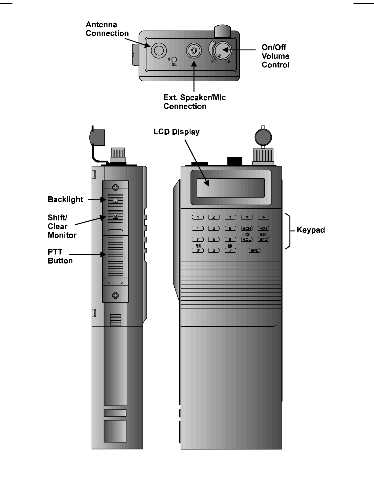
CONTROLS
QUICK REFERENCE GUIDE
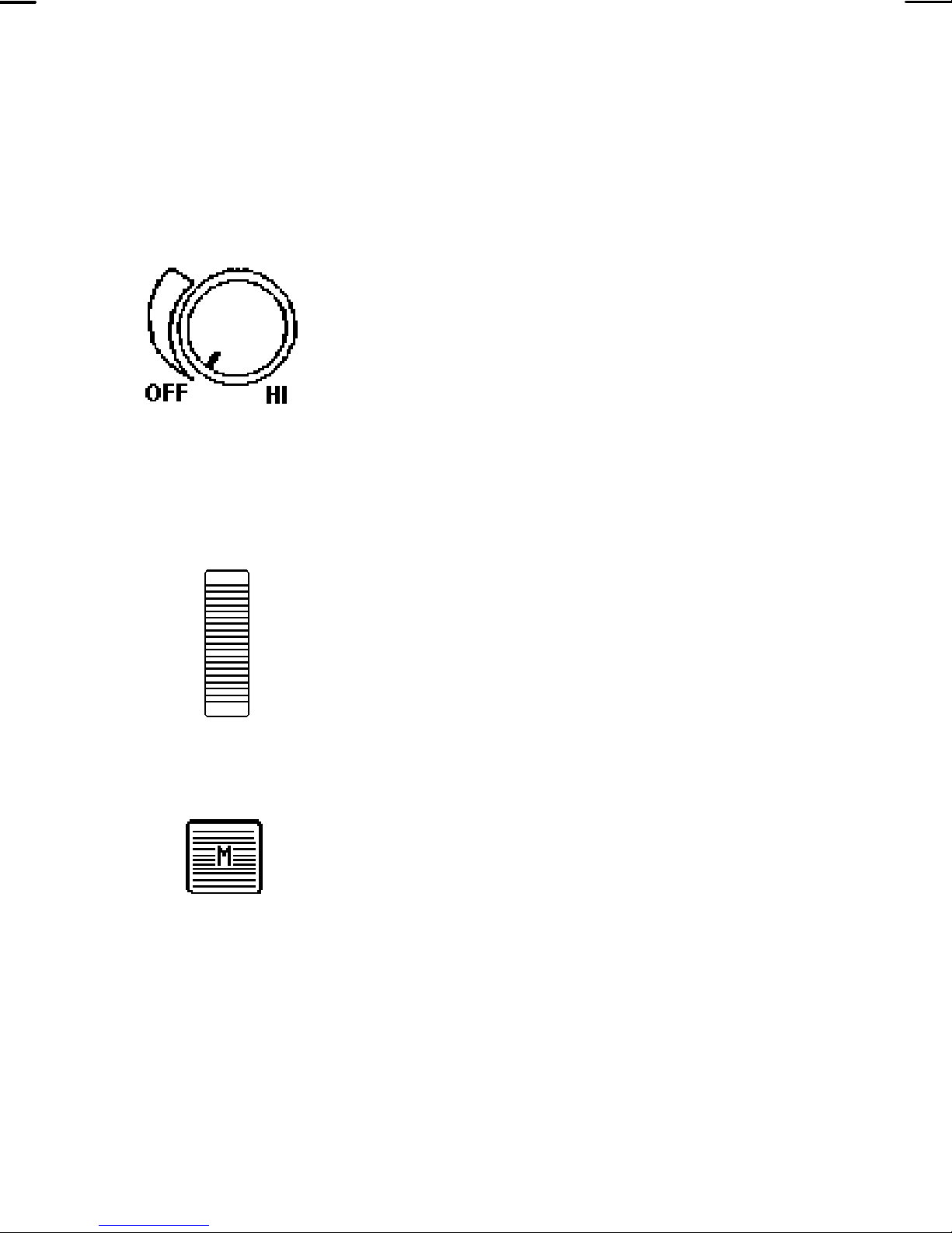
On/Off
Volume
PTT Button
The top, right clockwise rotation
applies power with a mechanical
click sound, and a full counter
clockwise rotation, removes power
with a click sound. A clockwise
rotation makes the volume level
increase and a counter clockwise
rotation decreases the volume level.
The radio can be programmed to
beep once after power is applied,
indicating it is ready for use.
Pressing the PTT button (located on
the side of the radio) will key the
radio’s transmitter and perform the
Shift/Clear/
Monitor
necessary steps to acquire a
communication channel.
All alternate key functions are
accessed by pressing the
Shift/Clear/Monitor button and then
pressing the desired function key.
Trunked - Pressing the Shift/Clear/
Monitor button twice (double click)
will invoke the CLEAR func tion which
is used to exit the Special Call mode
and return to the normal System/
16
Group display.
Page 17
Conventional - Pressing and holding
the Shift/Clear/Monitor button twice
(double click) will enable
MONITORING the channel for
activity by unsquelching the receiver.
All transmissions will be heard, even
if Channel Guard protected.
Backlight
System/Group
Select Switch
<
>
The side, uppermost mounted
momentary switch when pressed
illuminates the LCD for a preprogrammed time perod.
The Select buttons
switches are used to increment or
decrement the current Group/
Channel selection. Pressing the
Shift button and then the
>
decrement the System selection.
The Select buttons are also used to
increment or decrement the Special
Call selection while in the Special
buttons will increment or
<
and
<
>
and
H
Call mode.
The HOME/Emergency key is used
to automatically select a desired
Group and/or System by pressing
and holding the key for a
programmed duration. The HOME/
Emergency key is also used to
declare emergencies by pressing
and holding the key for a preprogrammed duration. Emergency
messages may only be issued on
17
Page 18

EDACS systems.
S
s
T
Pressing the SPC (Special) key will
put the radio in the Special Call
mode. From the Special Call mode
the radio is able to make individual
and interconnect calls. The key is
active with trunked systems only.
The SCAN-Add/Delete key is used to
enable the Scan mode and to add or
delete Groups/Channels to the scan
list.
The STORE key is used to store
individual call numbers and interconnect calls. T his key is active with
trunked systems only.
MUTE The MUTE key is used to
mute/unmute the radio. Mute is also
a second function as described in
Lock section
LOCK The LOCK key in combination with
the SHIFT/CLEAR/MONITOR key is
used to lock the keypad. All buttons
and keys will be locked except the
PTT,
TOR, and the LOCK.
The
H
r
, SHIFT/CLEAR/ MONI-
(Recall) key can be used
r
to recall manually entered individual
18
and interconnect calls in the EDACS
and GE-MARC systems.
Page 19
INDICATORS
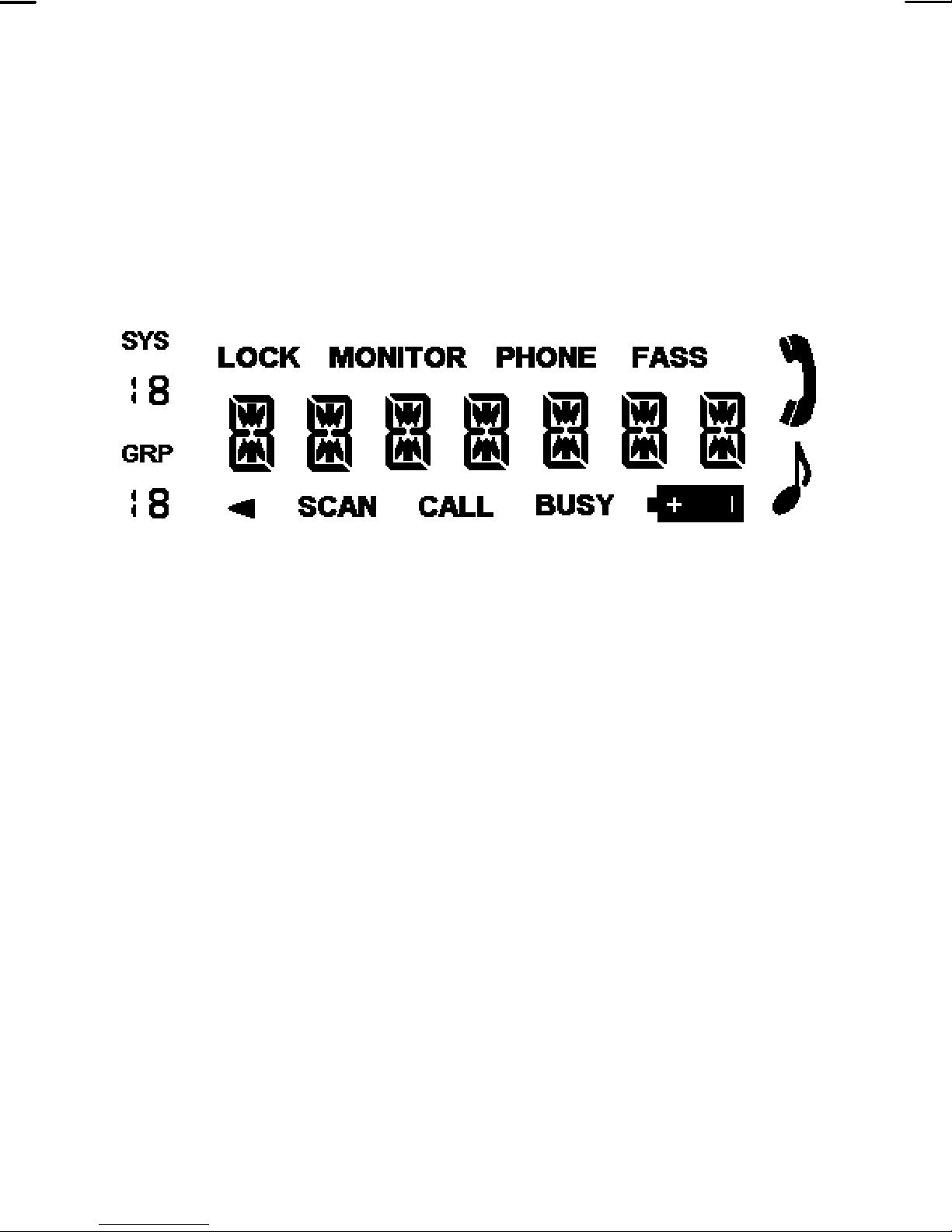
Alpha-numeric display, is a 7 character display that
identifies the selected System/Group and those
operating modes or error conditions. In addition there are
12 status indicators that are described on the following
pages.
The LCD backlighting can be program m ed to turn on
anytime the backlight switch is pressed or anytime a
button or key is pressed. It will remain on for a
programmable length of time after the button or key is
released. Backlighting is programmed on a per
Group/Channel basis or it may be programmed to
remain off at all times. Each radio that is programmed
with backlighting may also be programm ed to remain on
or off when the PTT bar is pressed.
SYS AND GRP/CHANNEL INDICATORS
SYS The SYSTEM display indicates the
number of the current EDACS, GE-
MARC, or Conventional system
selected.
19
Page 20

GRP The GRP (Group) display indicates
the number of the current Group in
an EDACS or GE-MARC System.
The GRP icon is suppressed while
operating from a Conventional
System, but will show channel
number.
STATUS INDICATORS
BUSY The Channel Busy flag is on when
the radio receives a call or when a
conventional channel is in use. The
flag is also on when transmitting on a
trunked channel.
The Battery flag is on when the
B
battery power is low and needs
charging.
SCAN The SCAN flag is on when Scan is
activated.
LOCK The LOCK flag is on when the
keypad lock function is active.
The V flag is used to indicate when a
V
trunked group or conventional
channel is scan enabled.
PHONE In EDACS or GE-MARC, the PHONE
20
P
and
when the radio is placed in the
Special Call mode.
status flags will be illuminated
Page 21

CALL The CALL icon will be illuminated
when the radio receives an individual
call in EDACS or GE-MARC modes.
Indicates that the “key press” tones
QQ
Monitor Indicates that the monitor mode has
The radio generates a number of alert tones to
are heard.
been enabled in a conventional
system.
ALERT TONES
indicate various events. T he following section describes
the alert tones.
STANDARD TONES
Power-UP If programmed, a tone will sound on
power-up after the radio passes the
self test.
Low Battery A low pitch tone will sound every 130
seconds when the battery is low and
needs charging.
Carrier Control
Timer
The Carrier Control Timer (CCT)
alert is a pulsed tone signal that
sounds whenever the PTT button is
continuously pressed for a preprogrammed length of time. After
nine seconds of pulsing the
21
Page 22

transmitter shuts down and
communications is interrupted. To
maintain communications, release
and re-key the PTT switch. This
resets the timer and turns the
transmitter back on. The CCT is a
built-in precaution against inadvertent use of the system.
TONES FOR TRUNKED OPERATION ONLY
Call Originate
(EDACS)
If programmed, a short tone is
sounded whenever the Push-To-Talk
(PTT) button is keyed and the radio
has acquired a channel. This tone
indicates the user may proceed to
talk.
Call Originate
(GE-MARC)
If programmed, a three tone alert is
sounded whenever the Push-To-Talk
(PTT) button is keyed and the radio
has acquired a channel. This tone
indicates the user may proceed to
talk.
Call Received If programmed, a single alert tone
Call Queued
(EDACS)
22
sounds when a group call is received
and a two tone alert (one high
followed by one low tone) is sounded
for an individual call.
If one short, high pitched tone
sounds after the transm itter is k eyed,
Page 23

this indicates that the system has
placed the request in a queue. This
tone sounds at both the transmitting
unit and the receiving unit(s),
indicating to the user on the receiving
end that they will receive a call
shortly. If the PTT is unkeyed while
in the queue, the radio will autokey
(automatically key the PTT) when a
channel becomes available. (See
Autokey below).
Autokey
(EDACS)
When the PTT is keyed to place a
call on the system, but the PTT is
released before getting to the
channel (e.g. a queued call), the
radio automatically keys on the
channel when it gets the assignment.
The radio generates a long beep and
holds the transmitter keyed for two
seconds. Pressing the PTT button
keeps the channel and sends the
message before this two second
time-out has expired.
System Busy EDACS - If you key the PTT bar and
hear three short, medium pitched
tones, this indicates that the
receiving party is already engaged in
another call or the system is busy
and its queue is full. You m ust rek ey
later to access the system.
23
Page 24

GE-MARC - If you key the PTT bar
and hear a low frequency tone for 1
second this indicates all channels are
busy.
Call Denied
(EDACS)
Out of Range/
System
A single low pitch beep will sound
when the PTT switch is keyed and
the request is denied by the system.
This happens if the unit is an invalid
user or if the unit is requesting an
unavailable service.
EDACS - A single pitched tone will
sound immediately after the PTT
switch is keyed indicating the radio is
out of range of the repeater. The
radio tries to place the c all f or a s hort
period (3 seconds) after the initial
attempt. The radio generates a
second low pitched tone when it
gives up trying to place the call. The
system is off the air or the radio
needs servicing when the radio is
within calling rage, and these tones
are heard.
GE-MARC - Five beeps will sound
shortly after the PTT switch is keyed
when the radio is out of range of the
repeater or the radio is inoperative.
If the “Call Retry” is active, the radio
will try the channel at twenty second
intervals for five minutes.
24
Page 25
ERROR MESSAGES
SYN LOC, if at anytime the Synthesizer is unable to
load and lock on the channel property, a SYN LOC
mess age will be displayed. If the SYN LOC mess age is
displayed on all systems, the radio has failed or has not
been programmed properly. The radio’s buttons and
keys will still operate with a SYN LOC message
displayed.
PRS ERR, message indicates the personality has
not been programmed into the radio.
KEYPAD LOCK
The keypad can be locked at any time to prevent
undesired key presses. To lock the k eypad when it is in
the unlocked state, press and release the LOCK (shifted
r
SHIFT/CLR/MO NITOR and LOCK (shifted
now be inhibited. If the Emergency function of the
key is disabled, the
) key. All buttons and keys except the PTT,
r
H
key will also be inhibited. If the
H
) will
H
key is programmed for Emergency or Emergency/
Home, then the key is not inhibited and an emergency
can still be declared on the Home System/Group or the
current System/Group (however programmed). To
unlock the keypad when it is in the locked state, press
and release the LOCK (Shifted
r
) key.
,
25
Page 26

KEYPAD MUTE
The keypad can be muted at anytime. To mute the
keypad when it is in the unmute state, press and release
the MUTE (shifted
T
) key. All buttons will be muted.
To unmute the keypad, press and release the MUTE
(shifted
T
), the keypad is now unmuted.
SCAT OPERATION
A SCAT (Single Channel Autonomous Trunking)
System operates with same set of features as a standard
EDACS system. The only user change relates to the
BSY indicator. Since only one channel, operating as both
control and working channel, exists in a SCAT System,
the BSY indicator will be ON when the SCAT channel is
in the working channel mode. When the transmission on
the channel is completed, the indicator turns OFF and
indicates the return of SCAT control channel signaling.
26
Page 27
EDACS OPERATION
RECEIVING A MESSAGE
1. Turn the radio on by rotating the
ON/OFF/VOLUME control clockwise from
the OFF detent position. After the radio has
passed the power-up self test an optional
tone will sound and the current System and
Group will be displayed. If the unit does not
pass the test, an error message will be
displayed (see ERROR MESSAGES
section) or the display will be blank.
2. Press the SHIFT/CLR/M ONITO R button and
then use the SELECT buttons
<
or
>
to select an EDACS system. The system
icon will indicate the current System
selected.
3. Use the SELECT buttons
<
or
>
to
select the desired group. The GRP icon will
indicate the current Group selected. The
radio is now ready to receive messages.
4. INDIVIDUAL CALL - If an individual call (call
directed only to your radio) is received, the
radio unsquelches on the assigned channel.
The BUSY flag lights. If programm ed on, the
individual call received tones (one high
followed by one low) will sound and the
originator’s ID or just “ID” (dependent upon
programming) is displayed for a short time.
27
Page 28
To answer call, sim ply press PTT and begin talking if
caller’s ID is still in dis play. If caller’s ID is no long in
display, press the
then press PTT and begin talking.
GROUP CALL - When the radio receives a group
call, it unsquelches on the assigned channel and
lights the BUSY flag. If programmed on, the group
call received tone (single tone) will sound. T he radio
can also be programm ed to display the Group nam e
originators ID.
INTERCONNECT CALL - If an interconnect call
(telephone call directed to your radio) is received, the
radio unsquelches on the assigned channel and the
BUSY flag turns on. If programmed on, the
interconnect call received tones (one high followed
S
key to display caller’s ID,
P
by one low) will sound. The PHONE and
flags will be displayed.
status
P
NOTE
The opt ional call received tones are pr ogrammed of f
by default.
5. Using the
necessary.
SENDING A MESSAGE
1. Turn the radio on and set the desired System and
VOLUME
knob, adjust the volume as
Group as described under RECEIVE A MESSAGE
steps 1-3.
28
Page 29

2. Observe the display for the absence of both the
BUSY indicator and the NC indicator to ensure that
no one is transmitting on the selected Group and
ensuring radio is in service area.
3. Press and hold the PTT bar. The radio will perform
the necessary signalling required to obtain a
communication channel. If the signalling is
unsuccessful, the radio will sound the appropriate
alert tone(s).
4. When the channel has been acquired, the red TX
LED on top panel and the BUSY status flag in the
display is illuminated and if programmed, the Call
Originate tone will sound.
5. Hold the radio about 3 inches from your mouth and
speak as you would normally into the microphone.
6. Release the PTT bar when the transmission is
complete and listen for any reply.
SQUELCH ADJUSTMENT
In normal operation the squelch is automatically set
by the radio and does not need adjusting. If it becomes
necessary to adjust the squelch, the squelch may be
adjusted using the following procedure:
1. Press and hold the SHIFT/CLR/MONITOR button.
2. Use the SELECT
the squelch. Pressing the SELECT
<
or
>
buttons to adjust
<
will open
29
Page 30
the squelch and pressing the SELECT
close the squelch.
NOTE
The radio must be on a Conventional System or an
EDACS working Channel (i.e. receiving a voice call)
to adjust the squelch. It is recommended to adjust
squelch from a Conventional System.
SENDING A SPECIAL CALL
>
will
1. Press the
mode and provide access to a pre-programmed
special call alpha-numeric list. Each selection from
the list is pre-programmed with either an individual
number or an interconnect number. If programmed,
the special call alpha-num eric will be displayed. The
PHONE and
while in the Special Call mode.
2. Press the SELECT
increment or decrement through the special call list.
To display the last seven digits of the individual or
S
P
P
key to put the radio into Special Call
status flag will also be illuminated
<
NOTE
or
>
buttons to
interconnect number currently selected, press and
hold the SHIFT/CLR/MONITOR button and then
press the
3. Individual - Once the desired individual special call
number is displayed, press and hold the PTT to
30
S
key.
Page 31

initiate the call. The radio performs the necessary
signaling required to obtain a working channel.
Interconnect - Once the desired interconnec t special
number is displayed, press and release the PTT to
initiate the call. The radio performs the necessary
signaling required to obtain a working channel.
4. Individual - When the signaling is successfully
completed the BUSY flag turn on and the Call
originate tone sounds. Speak directly into the
microphone. Release the PTT bar as soon as you
stop talking and wait for a reply.
Interconnect - When the signaling is successfully
completed the BUSY flag turns on and the proper
DTMF tones will be sent and heard at the speaker.
When someone answers, press the PTT bar and
speak directly into the microphone. Release the
PTT bar as soon as you stop talking. Messages
cannot be received when the PTT bar is pressed.
If the signaling is unsuccessf ul, the radio will remain
in the Special Call Mode and sound the appropriate
alert tone(s).
5. When the Call is complete, double click the
SHIFT/CLR/MONITOR button to exit the Special Call
mode and return to the normal System/Group
display.
The radio is also c apable storing and/or rec alling up
to 10 individual and 10 interconnect numbers in 2
31
Page 32
separate storage locations. These numbers are
manually entered and recalled from the keypad.
SENDING A MANUALLY ENTERED INDIVIDUAL
CALL
1. Press the
mode. The display displays the last accessed
Special Call name/number from the pre-programmed
Special Call selection. The PHONE and
flags will also be illuminated while in the Special Call
mode.
2. Enter the ID number of the radio to be called. The
last digit entered will always be displayed in the far
right hand side of the display. Any previously
entered digits will scroll left. Only the last seven
characters will be visible at a time with the leading
character scrolling of f the display upon each new key
entry.
S
key to put the radio into Special Call
P
status
P
To rec all th e last indivi dual num ber enter ed manual ly
from the key pad, press the
3. Press and hold the PTT bar to initiate the call. The
radio performs the necessary signaling required to
obtain a working channel.
32
NOTE
r
key.
Page 33
4. When the signaling is successfully completed the
BUSY flag turns on and the Call originate tone
sounds. Speak directly into the microphone.
Release the PTT bar as soon as you stop talking and
wait for a reply. Messages cannot be received when
the PTT bar is pressed. If the signaling is
unsuccessful, the radio will remain in the Special Call
Mode and sound the appropriate alert tone(s).
5. When the call in complete, double click the
SHIFT/CLR/MONITOR button to exit the Special Call
mode and return to the normal System/Group
display.
SENDING A MANUALLY ENTERED INTERCONNECT
CALL
1. Press the
S
key to put the radio into Special Call
mode. The radio displays the last accessed call
number from the pre-programmed Special Call
P
selection. The PHONE and
status flags will also
P
be illuminated while in the Special Call Mode.
2. Enter the telephone number to be called. The last
digit entered will always be displayed in the far right
hand side of the display. Any previously entered
digits will scroll left. Only the last seven characters
will be visible at a time with the leading character
scrolling off the display upon each new key entry.
33
Page 34
NOTE
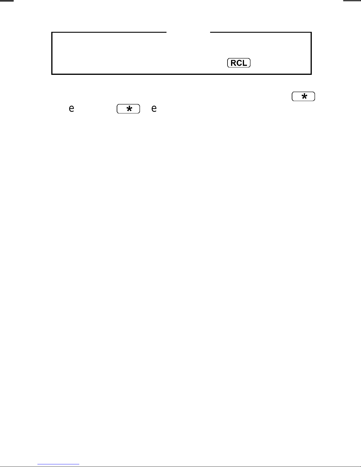
To recall the last interconnect number entered
manually from the keypad, press the
3. Complete the telephone entry by pressing the
key. The
*
key indicates the digits are for an
r
key.
*
interconnect call. This will not be displayed but a
tone will sound.
4. Press and release the PTT bar to initiate the call.
The radio perform s the necessary signaling required
to obtain a working channel. When the signaling is
successfully completed the BUSY flag lights and the
proper DTMF tones will be sent and heard at the
speaker. If the interconnect signaling is
unsuccessful, the radio will remain in the Special Call
Mode and sound the appropriate alert tone(s).
5. When someone answers, press the PTT bar and
speak directly into the microphone. Release the
PTT bar as soon as you stop talking. Messages
cannot be received when the PTT bar is pressed.
6. When the call is complete, double click the
SHIFT/CLR/MONITOR button to exit the Special Call
mode and return to the normal system/group display.
34
Page 35
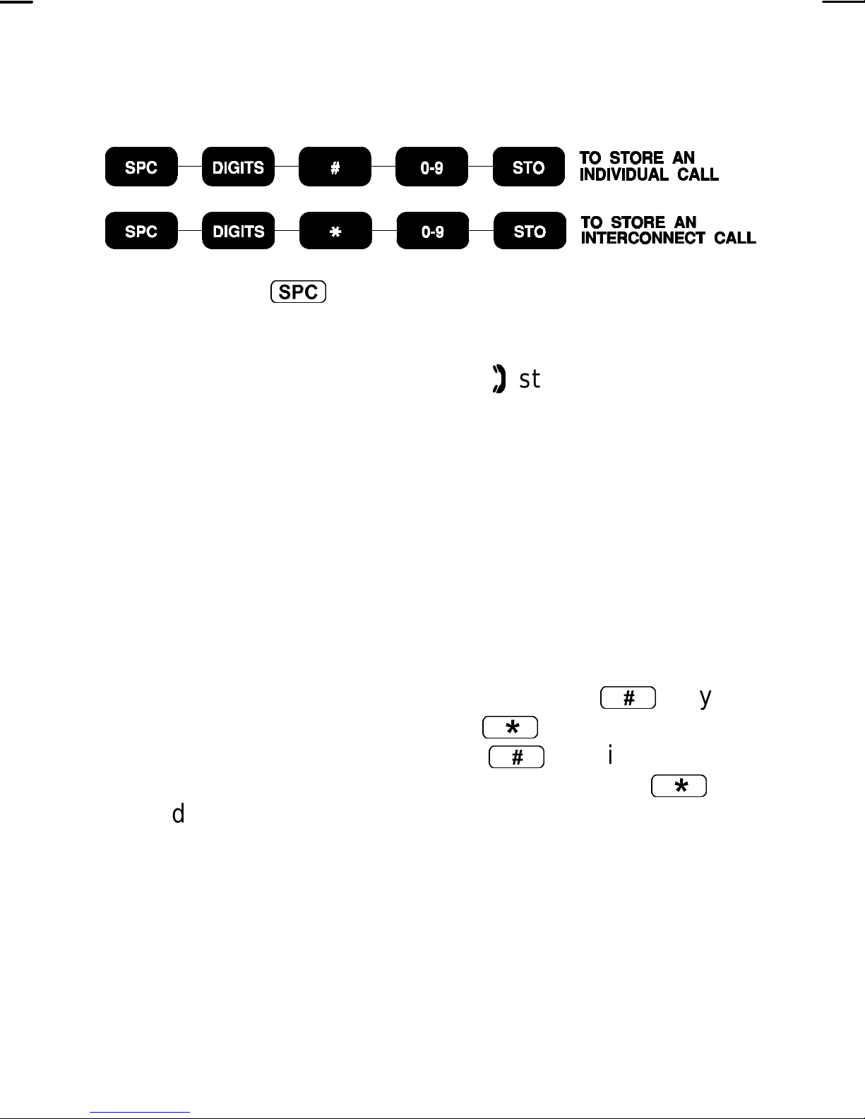
STORING INDIVIDUAL AND INTERCONNECT
NUMBERS
1. Press the
S
key to put the radio into Special Call
mode. The display displays the last accessed call
number from the pre-programmed Special Call
P
selection. The PHONE and
status flags will also
P
be illuminated while in the Special Call Mode.
2. Enter the ID number or telephone number of the
radio to be stored. The las t digit entered will always
be displayed in the far right hand side of the display.
Any previously entered digits will scroll left. Only the
last seven character s will be visible at a time with the
leading character scrolling of f the display upon each
new key entry.
3. Complete the entry by pressing the
#
key for
individual numbers and the
interconnect numbers. The
digits entered are for an individual call and
indicates the digits are for an interconnect call. They
will not be displayed but a tone will sound.
4. Enter a digit between 0 and 9 to select a storage
location. The storage location will not be displayed,
but a tone will sound. There are 10 storage locations
for individual numbers and 10 storage locations for
interconnect numbers.
*
#
key for telephone
key indicates the
*
key
35
Page 36
5. Press the
T
key to complete the storage
procedures.
6. Double click the SHIFT/CLR/MONITOR button to
exit the Special Call mode and return to the normal
System/Group display.
RECALLING MANUALLY STORED INDIVIDUAL AND
INTERCONNECT NUMBERS
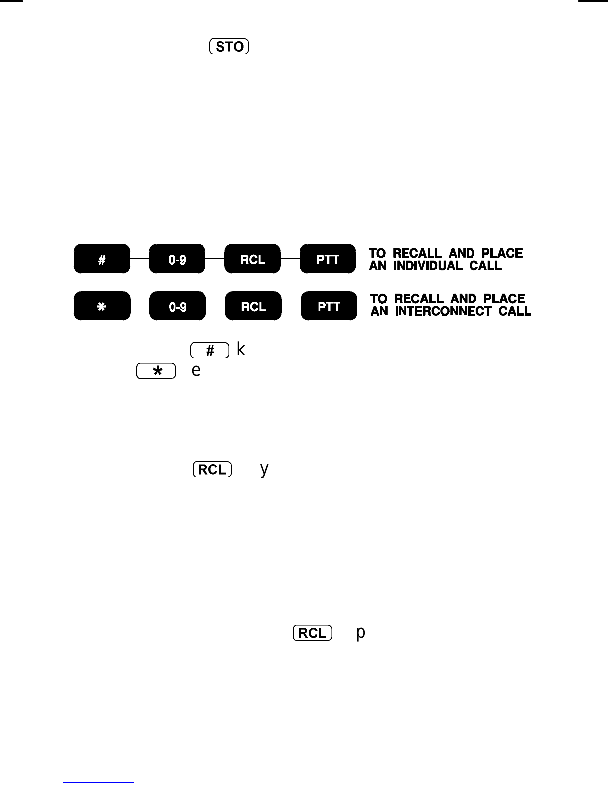
1. Press the
the
*
#
key to recall the individual call list or
key to specify the interconnect call list. The
screen will blank and a tone will sound.
2. Enter the desired storage location number (0-9).
3. Press the
r
key and the radio will switch to the
Special Call mode. If the number is from the
individual call list, the ID number will be displayed. If
the number is f rom the interconnect call list, the last
seven digits of the telephone number will be
displayed.
If the mem ory location is blank the radio will sound a
low pitch tone after the
r
is pressed.
4. Individual - Once the desired individual call number
is displayed, press and release the PTT to initiate the
36
Page 37

call. The radio performs the necessary signaling
required to obtain a working channel.
Interconnect - Once the desired interconnec t special
call number is dis played, press and release the PT T
to initiate the call. The radio perf orm s the neces sary
signaling required to obtain a working channel.
5. Individual - When the signaling is successfully
completed the BUSY flag turns on, TX indicator
turns red and the Call originate tone sounds. Speak
directly into the microphone. Release the PTT bar
as soon as you stop talking and wait for a reply.
Interconnect - When the signaling is successfully
completed the BUSY flag turns on and the proper
DTMF tones will be sent and heard at the speaker.
When someone answers, press the PTT bar and
speak directly into the microphone. Release the
PTT bar as soon as you stop talking. Messages
cannot be received when the PTT bar is pressed.
If the signaling is unsuccessf ul, the radio will remain
in the Special Call mode and sound the appropriate
alert tone(s).
6. When the call is complete, double click the
SHIFT/CLR/MONITOR button to exit the Special Call
mode and return to the normal System/Group
display.
37
Page 38
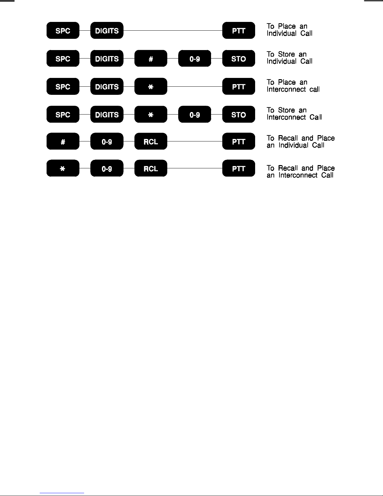
DTMF OVERDIAL
After the radio has acquired a working channel to
make a message trunked call, DTMF tones can be sent
by:
1. Pressing and holding the PTT bar.
2. Manually entering the desired numbers from the
keypad.
In the same manner, stored interconnect numbers
(tones) may be sent by:
1. Recalling the desired storage location as described
previously in the Recalling Manually Stored
Individual and Interconnect Numbers section.
2. Pressing the PTT bar to send the tones.
38
Page 39
SCAN OPERATION
ENABLE/DISABLE SCAN
To enable Group scanning, press and release the
s
is active. W hen scan is on, press and release the
key. The SCAN flag will illuminate to indicate s can
s
key to disable scan operation. The SCAN flag will be
extinguished when scan in turned off.
ADD/DELETE GROUPS
Groups can be added or deleted from the scan list
as necessary. To add Groups to the Scan list:
1. Select the desired Group to be added. If the current
group is already included in the scan list, the V flag
will be illuminated.
2. To add the group to the scan list, press the
SHIFT/CLR/MONITOR button and then press the
V
s
key. The
flag will turn on and the group will
be included.
NOTE
Scan must be disabled to add a Group to the scan
list.
39
Page 40

DELETE GROUPS
1. Select the desired Group to be deleted. If the
current group is already included in the scan list, the
V
flag will be illuminated.
2. To delete the group from the scan list, press the
SHIFT/CLR/MONITOR button and then press the
s
key. The V flag will turn off and the group will
be removed from the scan list.
WIDE AREA AND PRIORITY SYSTEM SCANNING
(OPTIONAL)
Radios operating within an EDACS system may be
programm ed for W ide Area Scan operation for multi-site
applications. Upon the loss of the currently selected
system’s control channel, radios m ay be program med to
automatically scan other systems. If a new control
channel is found, the radio will switch to the new system
and sound and alert tone. Group selection may change
upon switching to the new system.
The radio m ay also be programmed for priority wide
area system scan. A priority system m ay be assigned to
each system programmed into the radio. Radios
programm ed in this manner will scan the priority trunked
system’s control channel once every one, two, three, or
four minutes (programm able). This priority scan timer is
reset each time the PTT bar is pressed.
40
Page 41

PROSOUND™ (OPTIONAL)
The radio m ay be programm ed f or ProSound s ystem
scan operation for multi-site applications. ProSound
scanning is an enhanced replacement for wide area
system scanning. This algorithm insures that the radio
continually receives high quality audio. When the
selected system degrades to a pre-programmed level,
the radio begins searching for the best adjacent system
on a part time basis. Once a better system is found the
radio changes to the new system and sounds a tone.
should the control channel be lost completely, the radio
will scan the adjacent systems until a suitable one is
found.
DYNAMIC REGROUPING (OPTIONAL)
Dynamic Regrouping is a feature which allows the
System Manger to dynamically program new groups into
selected radios. Upon development of the regrouping
plan, the site controller sends each radio the regroup
plan number, “group position”, and activate/deactivate
comm ands. W hen the radio is regrouped, it will alert the
user and displays the regroup number “(nn = 01 - 08)” in
the 6th digit of the display.
NOTE
The regroup is identified by the leading zero in the 6th
digit of the Display field. This zero is normally
suppressed in Group 1-8.
41
Page 42

HOME/EMERGENCY KEY DEFINITION
The
H
key can be programmed in one of the
following configurations:
1. Emergency Enabled and Home Enabled - The radio
will switch to the programmed home System and/or
Group, and send an emergency transmission.
2. Emergency Enabled and Home Disabled - T he radio
will send and emergency transmission on the
Current System/Group.
3. Emergency Disabled and Home Enabled - T he radio
will switch to the home System and/or Group.
4. Emergency Disabled and Home Disabled - The key
is not active.
EMERGENCY OPERATION (OPTIONAL)
If the radio receives an Emergency Channel
Assignment, an alert tone will sound if programm ed and
EMRGNCY will be displayed.
Sending An Emergency Call
To enable an Emergency transmission:
1. Press and hold the
H
key for the programmed
duration. If programmed, EMRGNCY will be
displayed and a alert tone will sound.
42
Page 43
NOTE
The radi o may be progr ammed for both Quiet and/or
Blind mode in which case no alert tone is heard
and/or the display does not change respectively. If
programmed to display an EMRGNCY, the radio’s
disp lay w ill ret u rn to no rm al op eration once the PTT is
pressed.
2. The radio transm its an emergency message until an
Emergency Channel Assignment is received.
3. Upon receipt, the radio begins operation on the
programmed System/Group (see the Home/
Emergency Key Definitions section).
4. Press the PTT bar and speak directly into the
microphone in a normal voice.
5. Release the PTT bar when the transmission is
complete and listen for a reply.
HOME
The radio can be programmed to automatically
switch to a home System and/or Group by pressing and
holding the
H
key for the programm ed duration. The
radio will also transit an emergency message on the
home System and/or Group if programmed (see the
Emergency Operation section).
43
Page 44

This page intentionally left blank
44
Page 45
GE-MARC OPERATION
RECEIVING A MESSAGE
1. Turn the radio on by rotating the
ON/OFF/Volume control clockwise from the
OFF detent position. After the radio has
passed the power-up self test an optional
tone will sound and the current System and
Channel will be displayed. If the unit does
not pass the test, an error message will be
displayed, or the display will be blank.
2. Press the SHIFT/CLR button and then use
the SELECT buttons
<
or
>
select a
GE-MARC system. The SYS icon will
indicate the current System selected.
3. Use the SELECT buttons
<
or
>
select the desired Group. T he GRP icon will
indicate the current Group selected. The
radio is now ready to receive messages.
4. INDIVIDUAL CALL - If an individual call (call
directed only to your radio) is received, the
radio unsquelches on the assigned channel
and the BUSY flag lights. The individual call
received tones (one high followed by one
low) will sound and ID (for individual call) is
displayed. The call received tones may be
programmed off.
45
Page 46

GROUP CALL - When the radio receives a group
call, it unsquelches on the assigned channel and
lights the “BUSY” flag. The group call received tone
(single tone) will sound (unless programmed off).
INTERCONNECT CALL - If an interconnect call
(telephone call directed to your radio) is received, the
radio unsquelches on the assigned channel and the
BUSY flag turns on. If the received tone s et was the
selected group tone set, then the radio will operate
as it does when it receives a group call f rom another
radio. If the tone set was the selected system’s
individual call tone set, the radio will operate as if it
had received an individual call from another radio.
5. Using the VOLUME knob, adjust the volume as
necessary.
SENDING A MESSAGE
1. Turn the radio on and set the desired System and
Group as described under RECEIVE A MESSAGE
steps 1-3.
2. Observe the display for the absence of the BUSY
indicator to ensure that no one is transmitting on the
selected Group.
3. Press and release the PTT bar. The radio will
perform the nec essary signaling required to obtain a
communication channel.
46
Page 47

The radio is out of range or the radio is operative
when the signaling is unsuccessful, a NO SRVC
message is displayed and a sequence of f ive beeps
are heard at the speaker. Any subsequent attempt
to initiate a call within the next 20 seconds will be
ignored.
All channels are busy when the signaling is
unsuccessful and a one second low frequency tone
is heard at the speaker. The call will not be retried
automatically.
NOTE
If the “Call Retry” option is active, the radio will try the
channel at twenty second intervals for five minutes
before returning to the normal System/Group display.
4. When the channel has been acquired, the BUSY flag
is illuminated and, if program med, the Call Originate
tones (three tone alert) will sound.
5. Press PT T bar. The TX indic ator will light red. Hold
the radio about three inches from your mouth and
speak as you would normally into the microphone.
6. Release the PTT bar when the transmission is
complete and listen for any reply.
47
Page 48
SENDING A SPECIAL CALL
1. Press the
mode which also provides access to a preprogrammed special call list. Each selection from
the list is programmed with either an individual
number or an interconnect num ber. If programmed,
the special call list is c apable of displaying an alphanumeric field. The PHONE and
illuminated while in the Special Call mode.
2. Press the SELECT
increment or decrement through the special call list.
S
key to put the radio into Special Call
P
flag will also be
P
<
or
>
buttons to
NOTE
To display the last seven digits of the individual or
interconnect number currently selected, press and
hold the SHFT/CLR/MONITOR button and then press
the
S
3. Individual Call - Once the desired individual special
call number is dis played, press and release the PT T
to initiate the call. The radio perf orm s the neces sary
signaling required to obtain a working channel.
Interconnect Call - Once the desired interconnect
special call number is displayed, press and release
the PTT to initiate the call. The radio performs the
necessary signaling required to obtain a working
channel.
key.
48
Page 49

4. Individual Call - When the signaling is successfully
completed the BUSY flag turns on and the Call
originate tones (three tone alert) sound. Press the
PTT bar and speak directly into the microphone.
Release the PTT bar as soon as you stop talking and
wait for a reply.
Interconnect Call - When the signaling is
successfully completed the BUSY flag turns on and
the proper DTMF tones will be sent and heard at the
speaker. When someone answers, press the PTT
bar and speak directly into the microphone. Release
the PTT bar as soon as you stop talking. Messages
cannot be received when the PTT bar is pressed.
5. The radio is out of range or the radio is inoperative
when the signaling is unsuccessful, the NO SRVC
will be displayed, and a sequence of five beeps are
heard at the speaker. Any subsequent attempt to
initiate a call within the next 20 seconds will be
ignored.
All channels are busy when the signaling is
unsuccessful and a one second low frequency tone
is heard at the speaker. The call will not be retried
automatically.
NOTE
If the “Call Retry” option is active, the radio will try the
channel at twenty second intervals for five minutes
before returning to the normal System/Group display.
49
Page 50

6. When the call is complete, double click the
SHIFT/CLR/MONITOR button to exit the Special Call
mode and return to the normal System/Group
display.
The radio is capable of the following from the Special
Call Mode:
• Storing and/or recalling up to 10 individual and 10
interconnect numbers in 2 separate storage
locations. These num bers are manually entered from
the keypad.
• Initiating individual and interconnect calls that are
manually entered from the keypad.
Each of these features are discussed in detail in the
following sections.
SENDING A PRE-PROGRAMMED SPECIAL CALL IN
CONFERENCE CALL
1. Preprogrammed Special Calls can also be initiated
using the selected group tone set. To initiate a
special call in Conference Call mode, press
7
to
put the radio into Conference Call mode, the
SYStem field will display SP and the GRP (group)
field will display the current selection number from
the special call list, if no special calls are
programmed then this field will be blank.
50
Page 51
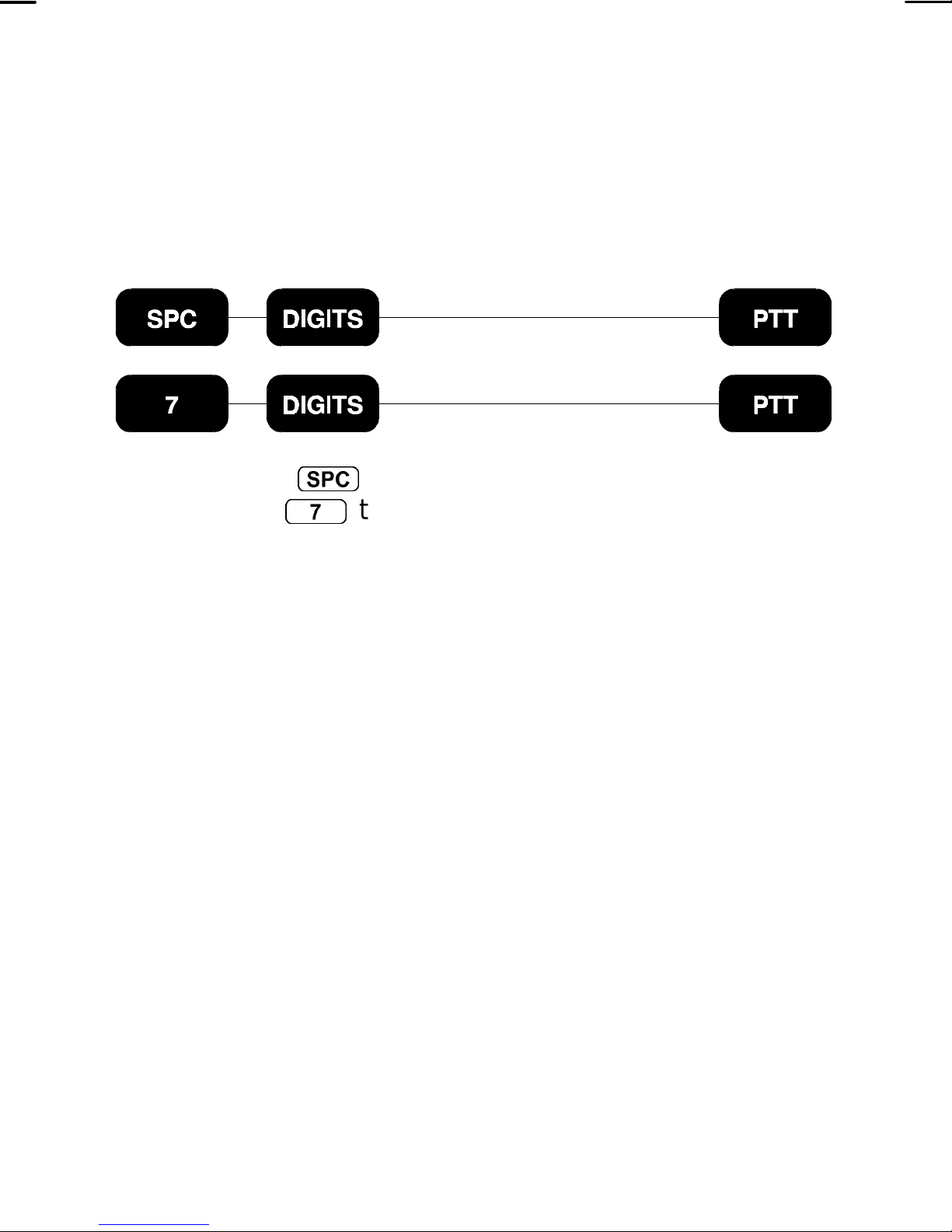
2. The program med call m ay now be sent following the
procedure described in SENDING A SPECIAL CALL
section.
SENDING A MANUALLY ENTERED INDIVIDUAL
CALL
1. Press the
mode or
S
7
key to put the radio into Special Call
to put the radio into Conference Call
mode. The SYStem field will display SP and the GRP
(Group) field will display the last accessed call
number from the preprogrammed Special Call
selection. or will be blank if no Special Calls are
programmed for this area.
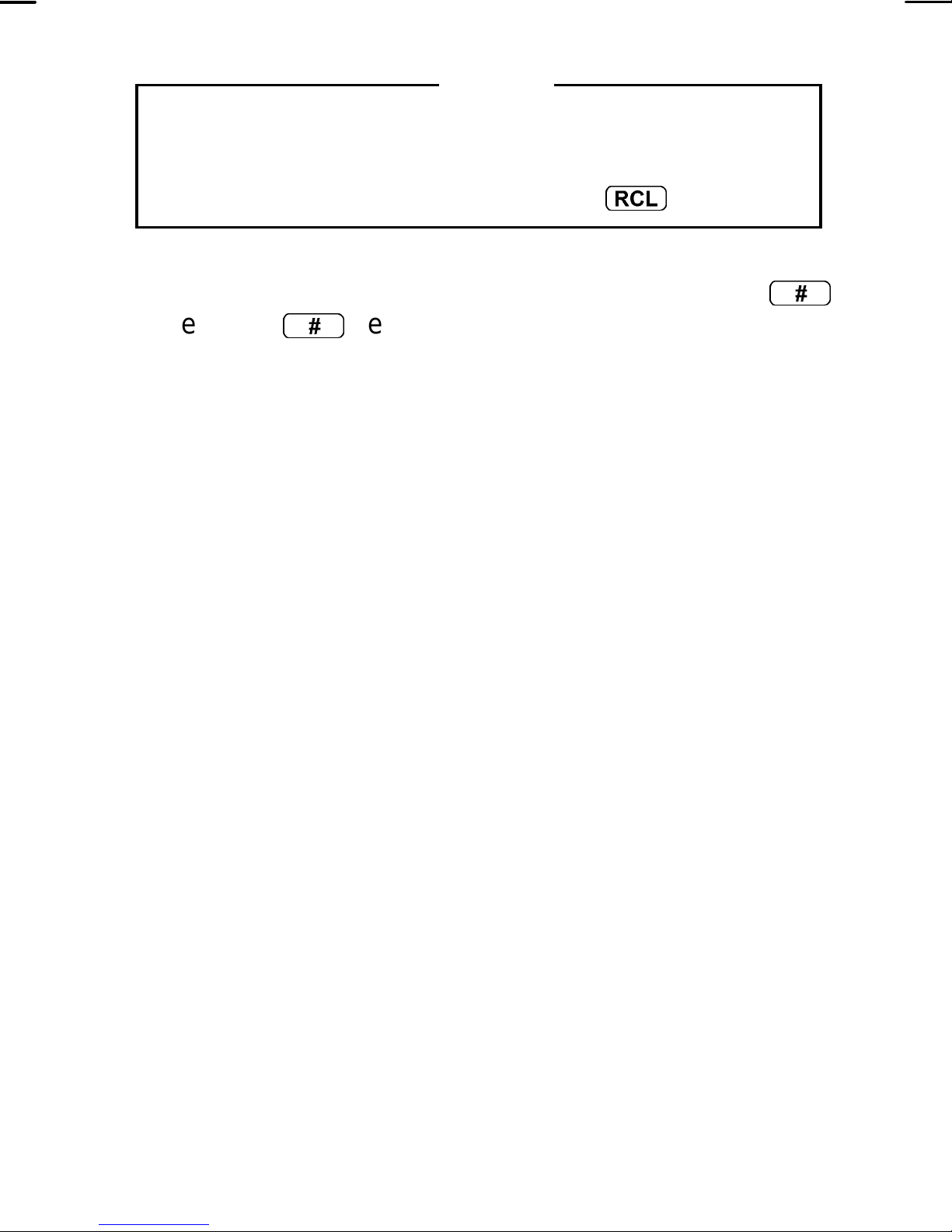
2. Enter the tone set of the radio to be called. The first
digit entered will cause the System field and the 10's
digit in the Group field to blank. The last digit entered
will always be displayed in the 1's digit of the Group
display. Any previously entered digits will scroll left.
Only four characters will be visible at a tim e with the
leading character scrolling of f the display upon each
new key entry.
51
Page 52
NOTE
To rec all th e last indivi dual number enter ed manual ly
from the key pad, press and hold the SHFT/CLR/
MONITOR button and then press the
3. Complete the tone set entry by pressing the
key. The
#
key indicates the digits entered are for
r
key.
#
an individual call. This will not be displayed but a
tone will sound.
4. Press and release the PTT bar to initiate the call.
The radio perform s the nec essary signalling required
to obtain a working channel.
5. When the signalling is successfully completed the
BUSY flag turns on and the Call Originate tones
(three tone alert) sound. Press the PTT bar and
speak directly into the microphone. Release the PTT
bar as soon as you stop talking and wait for a reply.
Messages cannot be received when the PTT bar is
pressed.
The radio is out of range or the radio is inoperative
when the signalling is unsuccessful, the NO SRVC
indicator is illum inated and a sequence of f ive beeps
are heard at the speaker. Any subsequent attempt to
initiate a call within the next 20 seconds will be
ignored. The radio can be cleared from this m ode by
double clicking the SHFT/CLR/MONITOR button.
All channels are busy when the signalling is
unsuccessful and a one second low frequency tone
52
Page 53
is heard at the speaker. The call will not be retried
automatically.
NOTE
If the “Call Retry” option is active, the radio will try the
channel at twenty second intervals for five minutes
before returning to the normal System/Group display.
6. When the call is complete, double click the
SHIFT/CLR/MONIT OR button to ex it the Special Call
mode or Conference Call mode and return to the
normal System/Group display.
SENDING A MANUALLY ENTERED INTERCONNECT
CALL
1. Press the
mode. or
S
7
key to put the radio into Special Call
to put the radio into Conference Call
mode. The SYStem field will display SP and the GRP
(Group) field will display the last accessed call
number from the preprogrammed Special Call
selection or will be blank if no Special Calls are
programmed for this area.
53
Page 54
2. Enter the telephone number to be called. The first
digit entered will cause the System field and the 10's
digit in the Group field to blank. The last digit entered
will always be displayed in the 1's digit of the Group
field. Any previously entered digits will scroll left.
Only four characters will be visible at a tim e with the
leading character scrolling of f the display upon each
new key entry.
NOTE
To recall the last interconnect number entered
manually from the key pad, press and hold the
SHFT/CLR/MONITOR button and then press the
r
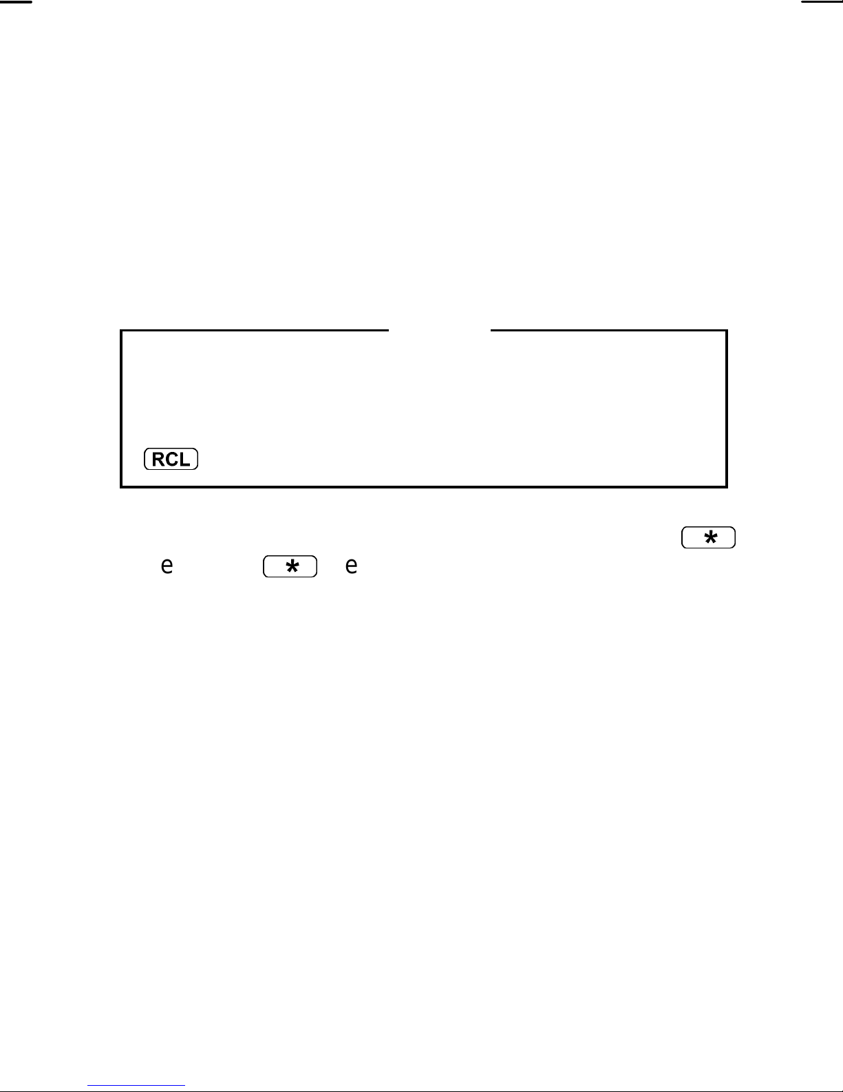
3. Complete the telephone entry by pressing the
key. The
key.
*
*
key indicates the digits are for an
inter-connect call. This will not be displayed but a
tone will sound.
4. Press and release the PTT bar to initiate the call.
The radio perform s the nec essary signalling required
to obtain a working channel. When the signalling is
successfully completed the BUSY flag lights and the
proper DTMF tones will be sent and heard at the
speaker.
The radio is out of range or the radio is inoperative
when the signalling is unsuccessful, the NO SRVC
indicator is illum inated and a sequence of f ive beeps
are heard at the speaker. Any subsequent attempt to
initiate a call within the next 20 seconds will be
54
Page 55

ignored. The radio can be cleared from this m ode by
double clicking the SHFT/CLR/MONITOR button.
All channels are busy when the signalling is
unsuccessful and a one second low frequency tone
is heard at the speaker. The call will not be retried
automatically.
NOTE
If the “Call Retry” option is active, the radio will try the
channel at twenty second intervals for five minutes
before returning to the normal System/Group display.
5. When someone answers, press the PTT bar and
speak directly into the microphone. Release the PTT
bar as soon as you stop talking. Messages cannot
be received when the PTT bar is pressed.
6. When the call is complete, double click the
SHIFT/CLR/MONIT OR button to ex it the Special Call
mode and return to the normal system/group display.
55
Page 56
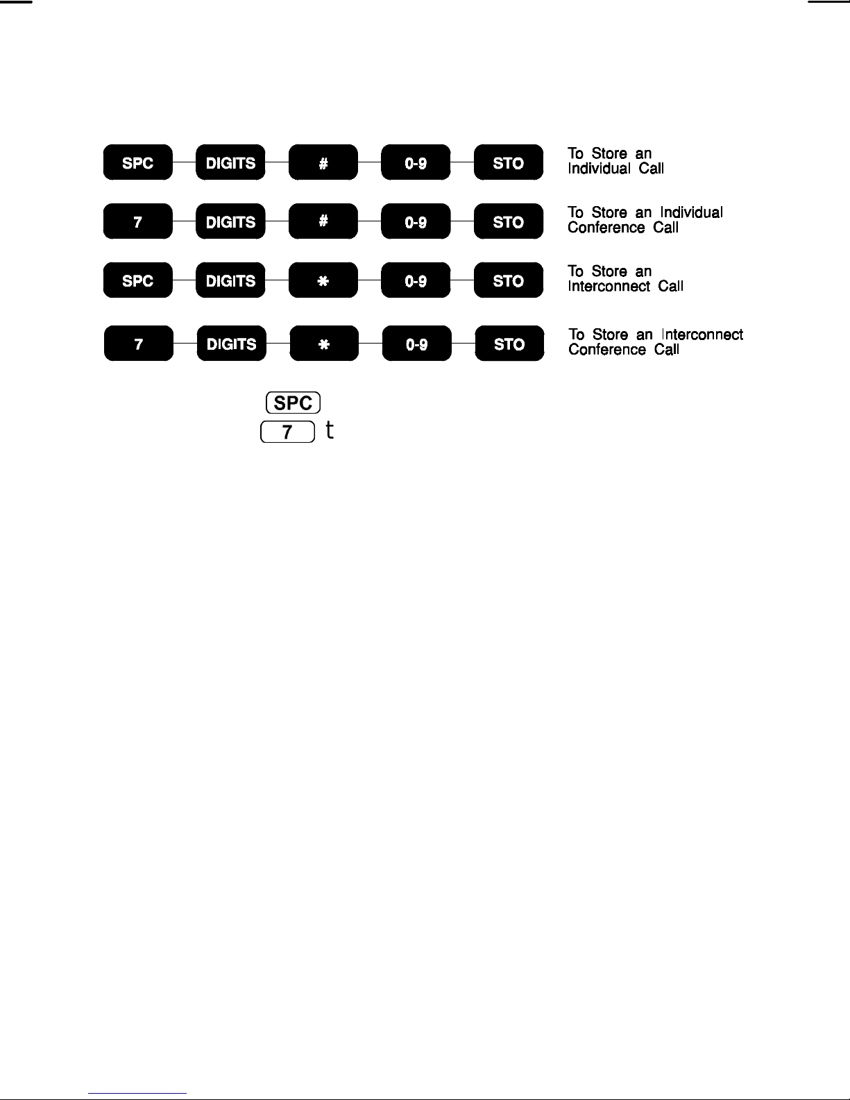
STORING INDIVIDUAL AND INTERCONNECT
NUMBERS
1. Press the
mode. or
S
7
key to put the radio into Special Call
to put the radio into Conference Call
mode. The SYStem field will display SP and the GRP
(Group) field will display the last accessed call
number from the preprogrammed Special Call
selection or will be blank if no Special Calls are
programmed for this area.
2. Enter the tone set (individual call) or telephone
number to be stored. The first digit entered will
cause the System display and the 10's digit in the
Group field to blank. The last digit entered will always
be displayed in the 1's digit of the Group field. Any
previously entered digits will scroll left. Only four
characters will be visible at a time with the leading
character scrolling of f the display upon each new key
entry.
56
Page 57
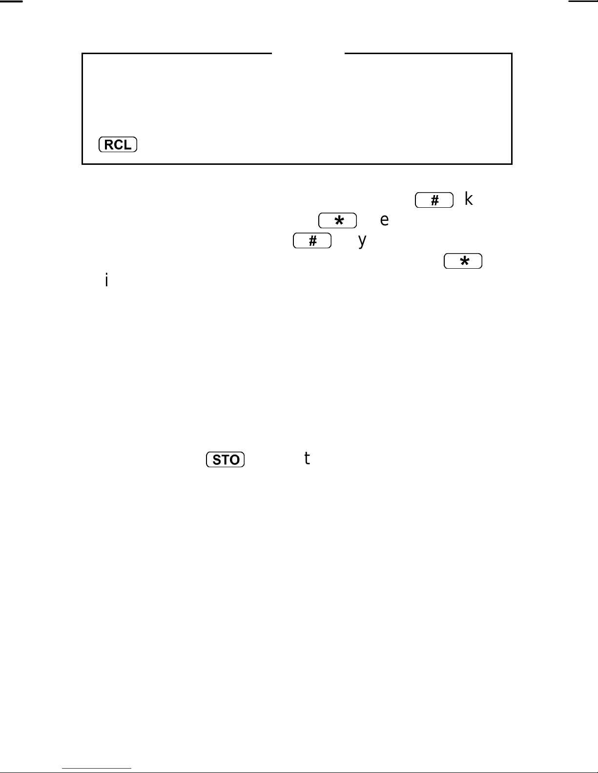
NOTE
To recall the last interconnect number entered
manually from the key pad, press and hold the
SHFT/CLR/MONITOR button and then press the
r
3. Complete the entry by pressing the
individual calls and the
interconnect calls. The
entered are for an individual call and
key.
*
#
#
key for
key for telephone
key indicates the digits
*
key
indicates the digits are for an interconnect call. T hey
will not be displayed but a tone will sound.
4. Enter a digit between 0 and 9 to select a storage
location. The storage location will not be displayed,
but a tone will sound. There are 10 storage locations
for individual numbers and 10 storage locations for
interconnect numbers.
5. Press the
T
key to complete the storage
procedure.
6. Double click the SHIFT/CLR/MONITOR button to
exit the Special Call mode and return to the normal
System/Group display.
57
Page 58
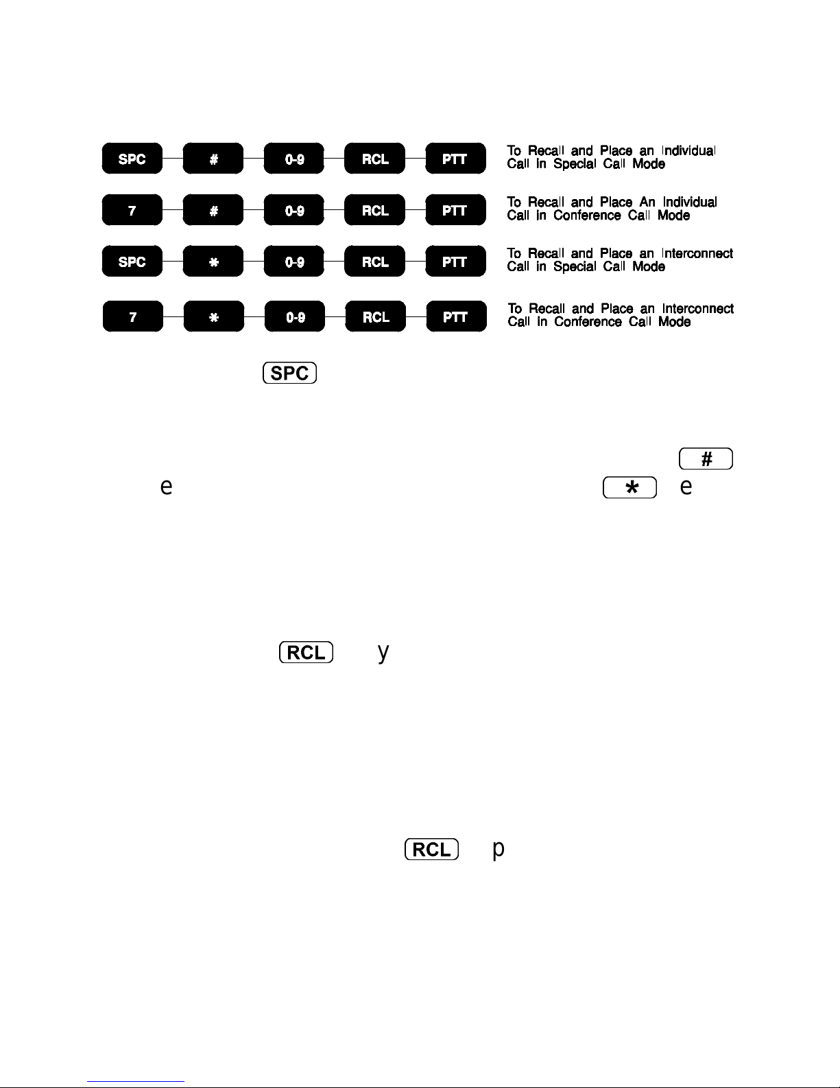
RECALLING MANUALLY STORED INDIVIDUAL AND
INTERCONNECT NUMBERS
1. Press the
S
key to put the radio into Special Call
mode to send a stored call using the programmed
special call tone set, otherwise the call will be sent
using the selected group tone set. Press the
key to recall the individual call list or the
*
key to
recall the interconnect call list. T he screen will blank
and a tone will sound.
2. Enter the desired storage location number (0-9).
3. Press the
r
key. If the number is from the
individual call list the last four digits of the tone set
will be displayed. If the number is from the
interconnect call list, the last four digits of the
telephone number will be displayed.
#
If the mem ory location is blank the radio will sound a
low pitch tone after the
4. Individual - Once the desired individual call number
is displayed , press and release the PTT to initiate
the call. The radio performs the nec essary signalling
required to obtain a working channel.
58
r
is pressed.
Page 59

Interconnect - Once the desired interconnec t special
call number is dis played,, press and release the PT T
to initiate the call. The radio performs the nec essary
signalling required to obtain a working channel.
5. Individual - When the signalling is successfully
completed the BUSY flag turns on and the Call
Originate tones (three alert tone) sound. Press the
PTT bar and speak directly into the microphone.
Release the PTT bar as soon as you stop talking and
wait for a reply.
Interconnect - When the signalling is successfully
completed the BUSY flag turns on and the proper
DTMF tones will be sent and heard at the speaker.
When someone answers, press the PTT bar and
speak directly into the microphone. Release the PTT
bar as soon as you stop talking. Messages cannot
be received when the PTT bar is pressed.
6. The radio is out of range or the radio is inoperative
when the signalling is unsuccessful, the NO SRVC
indicator is illum inated and a sequence of f ive beeps
are heard at the speaker. Any subsequent attempt to
initiate a call within the next 20 seconds will be
ignored. The radio can be cleared from this m ode by
double clicking the SHFT/CLR/MONITOR button.
All channels are busy when the signalling is
unsuccessful and a one second low frequency tone
is heard at the speaker. The call will not be retried
automatically.
59
Page 60
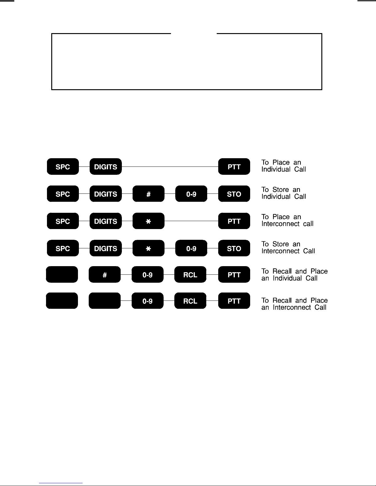
NOTE
If the “Call Retry” option is active, the radio will try the
channel at twenty second intervals for five minutes
before returning to the normal System/Group display.
7. When the call is complete, double click the
SHIFT/CLR/MONIT OR button to ex it the Special Call
mode an return to the normal System/Group display.
60
Page 61
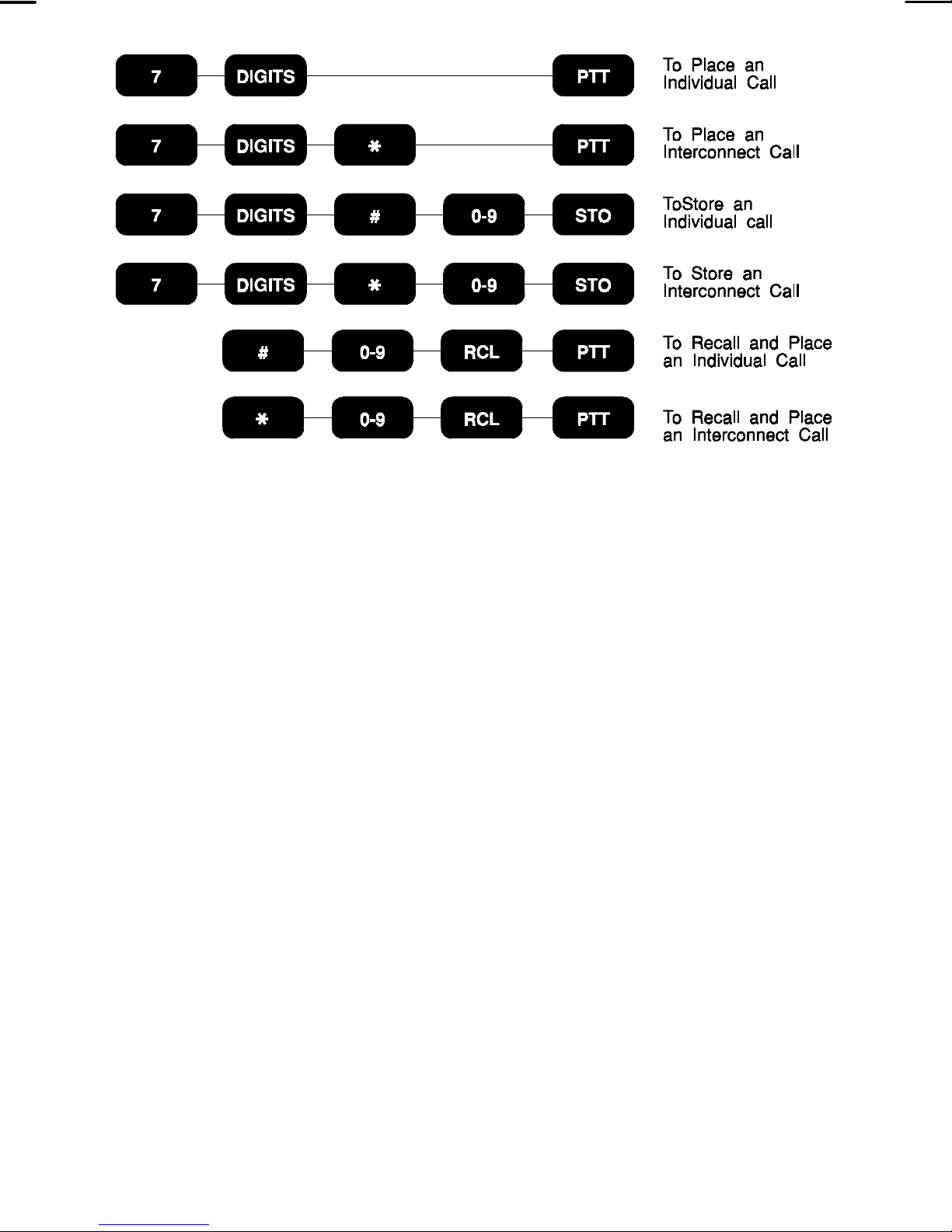
WIDE AREA SYSTEM SCAN
The Monogram Series EDACS Trunking Portable
radio operating within a GE-MARC system may be
programmed to scan up to 20 channels from other GEMARC systems. The radio will scan the channels in the
selected system and if its programmed c ollect tone is not
seen, then it will proceed to scan the channels of the
systems in its wide area scan list. The group selection
may change upon switching to the new system.
DIRECT MODE
The following section describes how to operate the
radio within a Direct Mode System (radio-to-radio).
Follow these procedures while operating on a Direct
Mode channel.
61
Page 62
Receiving A Message
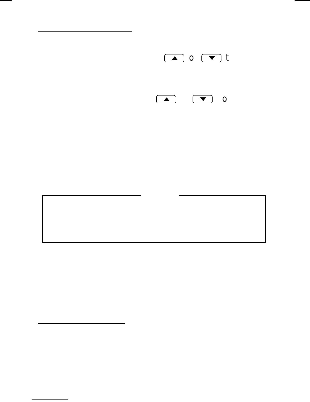
1. Press the SHIFT/CLR/MONITOR button and then
use the SELECT buttons
<
or
>
to select a
Direct Mode System. The SYStem display will
indicated the current System selected.
2. Use the SELect buttons
<
or
>
to select the
desired Channel. The radio is now ready to receive
message.
3. Press the SHIFT/CLR/MONITOR button twice
(“double click”) to disable squelch and monitor the
channel. Adjust the VOLUME control to the desired
audio level.
NOTE
Pressing the SHIFT/CLR/MONITOR twice (“double
click”) to monitor the channel may affect Busy Tone
signalling if programmed for the select channel.
4. When a message is received (and the correct Busy
Tone signal is decoded, if programmed and enabled)
the receiver will unsquelch and the message will be
heard.
Sending A Message
1. Turn the radio on and set the desired System and
Channel as described in the previous section.
62
Page 63

2. Ensure no one is transmitting on the selected
channel by pressing the SHIFT/CLR/MONITOR
button twice (“double click”) and/or observing the
display for the absence of the BUSY indicator to
ensure that no one is transmitting on the selected
Channel.
3. Holding the radio about 3 inches from your mouth,
press the PTT bar and speak as you would normally
into the microphone.
4. Release the PTT bar when the transmission is
complete and listen for any reply.
Sending A Manually Entered Interconnect Call
1. Select a channel in your radio system that has
telephone interconnect capability. The radio should
be programmed for DTMF operation on this channel.
2. Press and hold the PTT bar to key the transmitter.
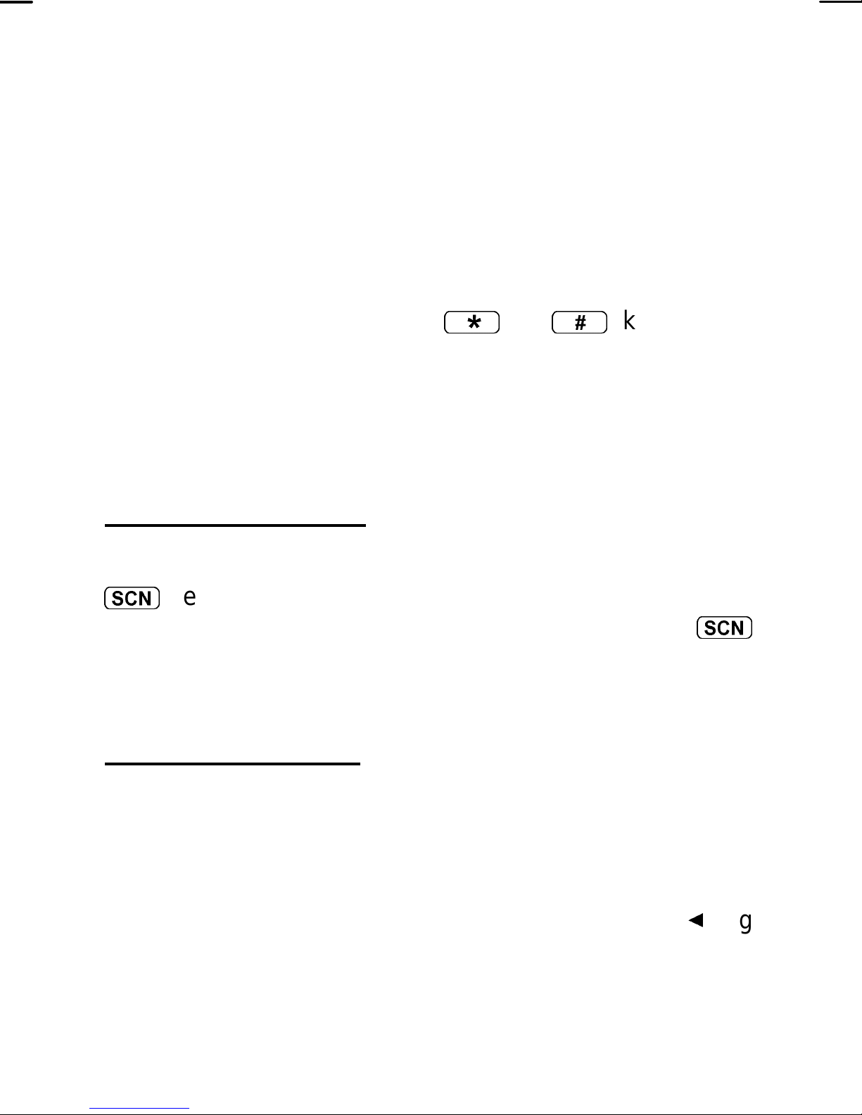
3. While holding the PTT bar, pres s either the
or the
#
key as required by the radio system to
*
key
obtain a telephone line. The radio will transmit the
selected tone.
4. Release the PTT bar and listen f or a dial tone. When
the dial tone is received, press and hold the PTT bar
and enter the desired telephone number. As you
enter each digit, the DTMF sidetone will be heard in
the speaker as the radio transmits the DTMF tone.
63
Page 64
5. After all the digits have been keyed in, release the
PTT bar.
6. When someone answers, press the PTT bar and
speak directly into the microphone. Release the PTT
bar as soon as you stop talking. Messages cannot
be received when the PTT bar is pressed.
7. At the completion of the call, press and hold the PTT
bar and then enter the
*
or
#
key as the
telephone interconnect system requires. Release the
PTT bar.
SCAN OPERATION
Enable/Disable SCAN
To enter Channel scanning, press and release the
s
is active. When scan is on, press and release the
key. The SCAN flag will illum inate to indicate scan
s
key to disable scan operation. The SCAN flag will be
extinguished when scan is turned off.
Add/Delete Channels
Channels can be added or deleted fr om the scan list
as necessary. To add channels to the scan list:
1. Select the desired channel to be added. If the current
channel is already included in the scan list, the V flag
will be illuminated.
64
Page 65
NOTE
Scan must be disa bled to add a c hannel to t he scan
list.
2. To add the channel to the scan list, press the
SHIFT/CLR/MONIT OR key and then press the
s
key. The V flag will illuminate and the channel will be
included.
To delete Channels from the scan list:
1. Select the desired channel to be deleted. If the
current channel is already included in the scan list,
the V flag will be illuminated.
2. To delete the channel from the scan list, press the
SHIFT/CLR/MONITOR button and then press the
s
key. The V flag will turn off and the channel will
be removed from the scan list.
65
Page 66

This page intentionally left blank
66
Page 67
CONVENTIONAL MODE OPERATION
The procedures in the following section
describes Conventional Mode operation. Each
conventional channel may be programmed with
one or more features such as Channel Guard or
telephone interconnect capability. Follow these
procedures if operating in a conventional system.
RECEIVING A MESSAGE
1. Turn the radio on by rotating the
ON/OFF/VOLUME contract clockwise from
the OFF detent position. After the radio has
passed the power-up self test an optional
tone will sound and the current System and
Group/Channel will be displayed. If the unit
does not pass the test, the display will be
blank.
2. Press the SHIFT/CLR/MONIT OR button and
then use the SELECT buttons
<
or
>
to select a Conventional system. The
SYStem display will indicate the current
System selected.
3. Use the SELECT buttons
<
or
>
to
select the desired Channel. The radio is now
ready to receive messages.
67
Page 68

4. Press the SHIFT/CLR/MONITOR button twice
("double click") to disable squelch and monitor the
channel. Adjust the VOLUME contract to the des ired
audio level.
5. When a message is received (and the correct
Channel Guard signal is decoded, if programmed
and enabled) the receiver will unsquelch and the
message will be heard.
SENDING A MESSAGE
1 Turn the radio on and set the desired System and
Channel as described in the previous section.
2. Ensure no one is transmitting on the selected
channel by pressing the SHIFT/CLR/MONITOR
button twice (“double click”) and/or observing the
display for the absence of the BUSY indicator to
ensure that no one is transmitting on the selected
Channel.
3. Holding the radio about 3 inches from your mouth,
press the PTT bar and speak as you would normally
into the microphone.
4. Release the PTT bar when the transmission is
complete and listen for any reply.
SQUELCH ADJUSTMENT
In normal operation the squelch is automatically set
by the radio and does not need adjusting. If it becomes
68
Page 69
necessary to adjust the squelch, the squelch may be
adjusted using the following procedure:
NOTE
The radio must be on a Conventional System or an
EDACS working Channel (i.e. receiving a voice call)
to adjust the squelch. It is recommended to adjust
squelch from a Conventional System.
1. Press and hold the SHFT/CLR/MONITOR button.
2. Use the
Pressing the
pressing the
<
>
or
>
<
keys to adjust the squelch.
will open the squelch and
will close the squelch.
SENDING A MANUALLY ENTERED INTERCONNECT
CALL
1. Select a channel in your radio system that has
telephone interconnect capability. The radio should
be programmed for DTMF operation on this channel.
2. Press and hold the PTT bar to key the transmitter.
3. While holding the PTT bar, press either the
*
key or the
#
to obtain a telephone line. The radio will transm it the
selected tone.
key as required by the radio system
69
Page 70
4. Release the PTT bar and listen f or a dial tone. When
the dial tone is received, press and hold the PTT bar
and enter the desired telephone number. As you
enter each digit, the DTMF sidetone will be heard in
the speaker as the radio transmits the DTMF tone.
5. After all the digits have been keyed in, release the
PTT bar.
6. When someone answers, press the PTT bar and
speak directly into the microphone. Release the PTT
bar as soon as you stop talking. Messages cannot
be received when the PTT bar is pressed.
7. At the completion of the call, press and hold the PTT
bar and then enter the
*
or
#
key as the
telephone interconnect system requires. Release the
PTT bar.
SCAN OPERATION
Enable/Disable SCAN
To enable Channel scanning, press and release the
s
is active. When scan is on, press and release the
key. The SCAN flag will illum inate to indicate scan
s
key to disable scan operation. The SCAN flag will be
extinguished when scan is turned off.
Add/Delete Channels
Channels can be added or deleted fr om the scan list
as necessary. To add channels to the scan list:
70
Page 71
NOTE
Scan must be disa bled to add a c hannel to t he scan
list.
1. Select the desired channel to be added. If the current
channel is already included in the scan list, the V flag
will be illuminated.
2. To add the channel to the scan list, press the
SHIFT/CLR/MONIT OR key and then press the
s
key. The V flag will illuminate and the channel will be
included.
To delete Channels from the scan list:
1. Select the desired channel to be deleted. If the
current channel is already included in the scan list,
the V flag will be illuminated.
2. To delete the channel from the scan list, press the
SHIFT/CLR/MONITOR button and then press the
s
key. The V flag will turn off and the channel will
be removed from the scan list.
71
Page 72

OPERATOR’S RADIO SETUP
RADIO TYPE: ________________________________
FREQUENCY BAND: __________________________
OPERATOR’S NAME: _________________________
EMERGENCY GROUP: ________________________
SYSTEM
NUMBER
SYSTEM
NAME
TRK/CNV GRP/CHN
NUMBER
GRP/CHN
NAME
USE
72
Page 73

SYSTEM
NUMBER
SYSTEM
NAME
TRK/CNV GRP/CHN
NUMBER
GRP/CHN
NAME
USE
73
Page 74

NICKEL CADMIUM BATTERY WARRANTY
A. Ericsson Inc. (hereinafter "Seller") warrants to the original purchaser for use
(hereinafter "Buyer") that nickel-cadmium batteries supplied by Seller shall
be free from defects in material and workmanship, and shall conform to its
published specifications for a period of twelve (12) months from the date of
purchase.
B. For purposes of this warranty, batteries shall be deemed defective if (1) the
battery capacity is less than 80% of rated capacity, or (2) the battery
develops leakage.
C. If any battery fails to meet the foregoing warranty, Seller shall correct the
failure by issuing a replacement battery upon receipt of the defective battery
at an Authorized Service Center (ASC). To obtain the name and address of
an ASC, ask your salesperson, consult the Yellow Pages, or call the number
printed at the bottom of this page.
D. Replacement batteries shall be warranted only for the remaining unexpired
warranty period of the original battery. This warranty becomes void if:
(1) The battery has been subjected to any kind of misuse, detrimental
exposure, or has been involved in an accident.
(2) The battery is used in equipment or service other than the radio
equipment for which it is specified.
E. The preceding paragraphs set forth the exclusive remedies for claims
(except as to title) based upon defects in or non-conformity of any battery,
whether the claim is in contract, warranty, tort (including negligence), strict
liability or otherwise, and however instituted. Upon the expiration of the
warranty period, all such liability shall terminate. The foregoing warranties
are exclusive and in lieu of all other warranties, whether oral, written,
expressed, implied or statutory. NO IMPLIED OR STATUTORY
W ARRANTIES OF MERCHANTABILITY OR FITNESS FOR PARTICULAR
PURPOSE SHALL APPLY. IN NO EVENT SHALL THE COMPANY BE
LIABLE FOR ANY INCIDENTAL, CONSEQUENTIAL, SPECIAL, INDIRECT
OR EXEMPLARY DAMAGES.
This warranty applies only within the United States.
1-800-528-7711 (Outside USA, 804-528-7711)
74
ECX-841C
Page 75

WARRANTY
A. Ericsson Inc. (hereinafter "Seller") warrants to the origi nal purchaser for use (herei nafter
"Buyer") that Equipment manufactured by Seller shall be free from defects in material,
workmanship and title, and shall conform to its published specificati ons. With respect to
any Equipment not manufactured by Seller (except for integral parts of Sel ler's Equipment
to which the warranties set forth above shall apply). Seller gi ves no warranty, and onl y the
warranty, if any, given by the manufacturer shall apply. Batteries are excluded from this
warranty but are warranted under a separate Nickel-Cadmium Battery Warranty.
B. Seller's obligati ons set forth in Paragraph C below shall apply onl y to failures to meet the
above warranties (except as to title) occurring within the following periods of time from
date of sale to the Buyer and are conditioned on Buyer's giving written notice to Seller
within thirty (30) days of such occurrence:
1. for fuses, incandescent lamps, vacuum tubes and non-rechargeable batteries,
operable on arrivalonly.
2. for parts and accessories (except as noted in B.1) sold by Seller's Service Parts
Operation, ninety (90) days.
3. for all other Equipment of Seller's manufacture, one (1) year.
C. If any Equipment fails to meet the foregoing warranties, Seller shall correct the failure at its
option (i) by repairing any defective or damaged part or parts thereof, or (ii) by making
available at Seller's factory any necessary repai red or replacement parts. Any repaired or
replacement part furnished hereunder shall be warranted for the remainder of the warranty
period of the Equipment in which it is installed. Where such fail ure cannot be corrected by
Seller's reasonable efforts, the parties will negotiate an equitable adjustment in price.
Labor to perform warranty service will be provided at no charge only for the Equipment
covered under Paragraph B.3, and only during the first three (3) months foll owing the date
of sale to the Buyer. Thereafter, labor will be charged at prevailing rates. To be eligible for
no-charge labor, service must be performed by an Authorized Service Center or other
Servicer approved for these purposes either at its place of business during normal
business hours, for mobile or personal equipment, or at the Buyer's location, for fixed
location equipment. Service on fixed location equipment more than thirty (30) miles from
the Service Center or other approved Servicer's place of business will include a charge for
transportation.
D. Seller's obligations under Paragraph C shall not apply to any Equipment, or part thereof,
which (i) has been modified or otherwise altered other than pursuant to Seller's written
instructions or written approval or, (ii) is normally consumed in operation or, (iii) has a
normal life inherently shorter than the warranty periods specified in Paragraph B, or (iv) is
not properly stored, installed, used, maintained or repaired, or, (v) has been subjected to
any other kind of misuse or detrimental exposure, or has been involved in an accident.
E. The preceding paragraphs set forth the exclusive remedies for claims (except as to title)
based upon defects in or nonconformity of the Equipment, whether the claim is in contract,
warranty, tort (including negligence), strict liability or otherwise, and however instituted.
Upon the expiration of the warranty period, all such li ability shall terminate. The foregoing
warranties are exclusive and in lieu of all other warranties, whether oral, written,
expressed, implied or statutory. NO IMPLIED OR STATUTORY WARRANTIES OF
MERCHANTABILITY OR FIT NESS FOR PARTICUL AR PURPOSE SHALL APPLY. IN NO
EVENT SHALL THE SELLER BE LIABLE FOR ANY INCIDENTAL, CONSEQUENTIAL,
SPECIAL, INDIRECT OR EXEMPLARY DAMAGES.
This warranty applies only within the United States.
1-800-528-7711 (Outside USA, 804-528-7711)
ECX-362S
75
Page 76

Police
State Police
Fire
Poison Control
EMERGENCY NUMBERS
Ambulance
Life Saving and
Rescue Squad
Ericsson Inc.
Private Radio Systems
Mountain View Road
Lynchburg, Virginia 24502
1-800-528-7711 AE/LZT 123 1875 R1A
(Outside USA, 804-528-7711) Printed in U.S.A.
 Loading...