

Page 1
LBI-38995
Mobile Communications
Monogram
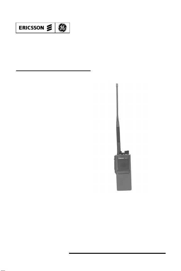
Low Band Portable Radio Unit
Model MGP 300
Series
Operator's Manual
Page 2

TABLE OF CONTENTS
OPERATING RULES AND REGULATIONS ............ 3
OPERATING TIPS ....................................................... 4
MAINTENANCE .......................................................... 6
INTRODUCTION ......................................................... 8
OPTIONS AND ACCESSORIES ................................. 9
PROGRAMMABLE FEATURES ................................ 9
CONTROLS AND INDICATORS ............................. 11
OPERATION ............................................................... 13
Radio On/Off ........................................................ 13
To Receive Messages ........................................... 13
To Transmit A Message ....................................... 14
BATTERY CHARGING AND CARE ....................... 15
Battery Pack Removal .......................................... 16
Rechargeable Battery Pack Disposal .................... 17
ANTENNA INSTALLATION .................................... 17
NICKEL CADMIUM BATTERY WARRANTY ...... 19
ALIGNMENT INSTRUCTIONS ................................ 20
Suggested Test Equipment ................................... 20
Pre-Alignment Notes ............................................ 21
EEPROM Programming ....................................... 21
Transmitter Alignment ......................................... 23
Receiver Alignment .............................................. 24
Antenna Tuning .................................................... 26
MONOGRAM SERIES WARRANTY ....................... 31
Copyright© September 1993, Ericsson GE Mobile Communications Inc.
2
Page 3

OPERATING RULES AND REGULATIONS
Two-way FM radio systems must be operated in
accordance with the rules and regulations of the Federal
Communications Commission (FCC) or, in Canada, the
Department of Communications (DOC). When operating
in other countries or localities, observe the appropriate
rules and regulations. As an operator of two-way radio
equipment, the user must be thoroughly familiar with the
rules that apply to the intended type of radio operation.
Following these rules will help to eliminate confusion,
assure the most efficient use of existing radio channels and
result in a smoothly functioning radio network. Violations
of these rules and regulations are punishable by fine,
imprisonment, or both.
When using the radio, remember these rules:
1. Interruption or refusal to yield a channel or radio
frequency for any distress or emergency message.
Emergency calls have priority over all messages.
Monitor the channel or frequency before sending
any messages. If someone is sending an emergency
message--such as reporting a fire or asking for help
in an accident--KEEP OFF THE AIR!
2. Use of profane, indecent or obscene language.
3. Transmission of false call letters or false distress or
emergency messages.
3
Page 4

4. Willful or malicious interference with any other
radio communications.
5. Repeat or otherwise make known anything
overheard on the radio. Conversations between
others sharing a communications channel must be
regarded as confidential.
6. Identify by use of proper call letters at specific
times. Refer to the rules that apply to the particular
type of operation for the proper procedure.
7. Adjustment of the equipment by anyone other than
a qualified, authorized or certified electronic
technician.
OPERATING TIPS
Antenna orientation and surrounding conditions are
important when using a portable radio unit. Operating in
low areas of terrain, under power lines or bridges, inside of
a vehicle or in a metal or steel framed building can
severely reduce the range of the radio unit. Mountains and
buildings can also reduce the effective range of the unit.
In areas where transmissions or reception is poor, some
improvement may be obtained by ensuring that the antenna
is vertical. Moving a few yards in another direction or
moving to a higher elevation may also improve
communications. In a marginal area, placing the radio unit
on a metal surface such as a car rood will also help.
4
Page 5

When operating with a repeater system utilizing Channel
Guard, as much as 250 milliseconds may be required for
tone recognition. Rapid operation of the PTT bar may
cause the first syllables of words to be clipped.
Battery condition is another important factor in the troublefree operation of the radio. Always use properly charged
batteries.
The radio is designed for use under a variety of
environmental conditions. However, a few precautions will
ensure long life of this radio, and they should be heeded
without fail.
• HIGH HUMIDITY Do not expose to continuous
rain or submerge in water.
• EXTREME HEAT Avoid direct exposure to
extreme heat. At very high temperatures, the nickelcadmium battery tends to self-discharge and reduce
operating time.
• LOW TEMPERATURES The radio can operate
in temperatures down to -30° C (-22° F). However, in
extreme cold, nickel-cadmium battery capacity is
reduced. If using in a very cold environment for an
extended period of time, keep the unit inside your
coat.
5
Page 6

MAINTENANCE
Your
Monogram
is designed to be maintenance free; however, a few
suggestions are offered to keep your radio in top operating
condition.
• Clean external surfaces of the radio with a mild
solution of dishwater detergent diluted in water. Apply
sparingly to avoid excessive moisture contact into
cracks and crevices. DO NOT submerge the radio, but
instead, use a nonmetallic brush to dislodge stubborn
particles. Thoroughly dry the surfaces with a soft, lint
free cloth.
• DO NOT use solvents or spirits for cleaning purposes
as they may permanently damage the housing.
• Clean the battery contacts on the bottom of the radio
with a lint free cloth to remove dirt, grease or other
foreign material that may impede good electrical
contact.
• Avoid physical abuse of the radio.
• DO NOT pound or drop the radio.
Series Model MGP 300 Portable Radio
• DO NOT carry the radio by the antenna.
• DO NOT disassemble the radio for purposes other
than changing the battery pack. There are no user
serviceable adjustments inside.
6
Page 7

• Check the battery and recharge, if necessary.
• Check that the antenna is properly installed and tuned
for the frequency of the radio unit.
• In case of difficulty, contact a service technician for
additional information.
7
Page 8

INTRODUCTION
The Ericsson GE
Band VHF Portable Radio is a lightweight, multichannel
radio offering both simplex and semi-duplex operation
with a wide range of options and accessories available.
This
Monogram
2 MHz segment of the frequency band with 5 watts RF
output power available. Up to 6 transmit/receive channels
may be programmed for operation. With the optional
Channel Guard tone module installed, individual channel
CTCSS tones may be programmed in either the transmit or
receive modes.
The radio is equipped with a 600 mAh nickel cadmium
battery pack to provide adequate service time between
recharging.
Monogram
Series portable radios operate within any
Series Model MGP 300 Low
IMPORTANT
Under U.S. Law, operation of an unlicensed radio
transmitter within the jurisdiction of the United States may
be punishable by a fine up to $10,000, imprisonment up to
two years, or both.
For programming, service and repair needs, see your local
Ericsson GE Service Representative. This radio must be
programmed and then an alignment of the transmitter and
receiver completed before using.
8
Page 9

OPTIONS AND ACCESSORIES
MHNC3R................................... Antenna, 30-35 MHz
MHNC3S...................................Antenna, 35-42 MHz
MHNC3T...................................Antenna, 42-50 MHz
MHAE3J.....................................Speaker/Microphone
MHCG1E.................................. CTCSS Tone Module
MHCH3V ............Dual Rate Desk Charger, 120 VAC
MHCH3W.............Dual Rate Multi-Unit Charger Kit,
120 VAC
MHHC5W............................................... Leather Case
MHPA5P.............600 mAh Battery, Nickel-Cadmium
MHTS3R........................................Radio Programmer
PROGRAMMABLE FEATURES
The following features are programmable on a per channel
basis:
• Transmit Channel Frequency
• Receive Channel Frequency
• Channel Guard (CTCSS) Frequencies - Tone only
9
Page 10
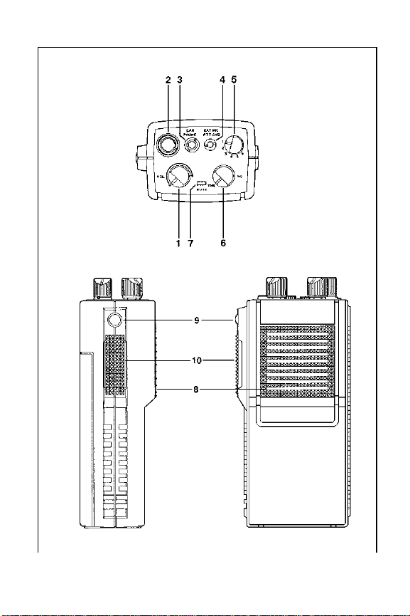
Figure 1 - Controls and Indicators
10
Page 11

CONTROLS AND INDICATORS
(1) ON/OFF/VOLUME Located on the top control
panel, it is used to turn the radio
on or off and to adjust the
listening level.
(2) ANTENNA Connector for antenna.
CONNECTOR
(3) EARPHONE JACK For use with optional
speaker/microphone. May also
be used for an external 8 ohm
speaker or earphone.
(4) EXT MIC/PTT/CHG For use with optional
speaker/microphone. This jack
is also used for charging the
battery pack, using the wall
charger supplied with the radio.
(5) CHANNEL SELECT Selects one of up to six
preprogrammed and designated
channels for operation.
(6) SQUELCH Used to silence the receiver
when no signal is received.
When Channel Guard is used,
rotate to TONE position.
11
Page 12

(7) BT/TX INDICATOR Red LED on when the
transmitter is keyed (normal
transmission). The LED will go
dim or goes out when the
battery voltage is low. The
battery must be replaced or
recharged to restore optimum
performance.
(8) MICROPHONE To transmit clear messages,
hold the portable radio so that
the microphone is about two
inches away from your mouth
and speak in a normal voice.
(9) MONITOR BUTTON Located just above the PTT bar.
When pressed, it defeats the
Channel Guard decode on the
receiver and unsquelches the
receiver to permit the user to
monitor the channel frequency.
Releasing the button returns the
receiver channel to normal
Channel Guard operation
(10) PTT BAR Located on the side of the radio.
Pressing the PTT bar keys the
transmitter and, if installed and
programmed, activates the
Channel Guard encoder for the
selected channel.
12
Page 13

OPERATION
RADIO ON/OFF
1. Turn the radio ON by rotating the VOLume control
fully clockwise (to the right) until you hear a click.
2. Turn the radio OFF by rotating the VOLume control
fully counterclockwise (to the left) until you hear a
click and feel the switch enter the detent position.
TO RECEIVE MESSAGES
1. Turn the radio ON and set the Channel Select switch
to the desired channel.
2. Unsquelch the radio by rotating the SQuelch control
counterclockwise until the receiver unsquelches (a
rushing sound coming from the speaker). Adjust the
VOLume control to desired listening level. Rotate the
SQuelch control clockwise until the squelch noise just
disappears (this is the threshold setting).
If the radio is equipped with the optional Channel Guard
Encoder/Decoder, press the MONITOR button to defeat
the Channel Guard Decoder and then adjust the VOLume
control for desired listening level. Release the MONITOR
button to return the receiver channel to normal Channel
Guard operation.
13
Page 14

TO TRANSMIT A MESSAGE
WARNING
Operation of the transmitter without a proper antenna
installed may result in permanent damage to the radio.
1. Hold the radio upright with the antenna in a vertical
position and the microphone about 2 inches away from
the mouth. Ensure that the antenna is away from the
face and eyes.
NOTE
Monitor the selected channel prior to sending a message.
TRANSMITTING ON AN ACTIVE CHANNEL MAY
INTERFERE WITH OTHER USERS.
2. Select the desired channel with the CHANNEL select
control. If the radio is equipped with the optional
Channel Guard Encoder/Decoder, press the
MONITOR button to defeat the Channel Guard
decoder and listen for activity on the channel.
3. When the channel is clear, release the MONITOR
button. Press and hold the PTT bar on the side of the
radio, and speak slowly and clearly into the
microphone. When you finish your transmission,
release the PTT bar to receive. The red LED on the top
14
Page 15

control panel will be on continuously while the PTT
bar is pressed and the radio is transmitting.
NOTE
The radio is equipped with a red LED transmit/battery
indicator (BT/TX). The LED will be lit continuously while
the PTT bar is pressed and the radio is transmitting.
If the BT/TX LED is dimly lit or goes out completely, this
indicates that the battery is weak and requires recharging.
Operation of the radio will be affected and the battery must
be replaced or recharged to restore optimum operation.
BATTERY CHARGING AND CARE
To ensure peak performance from your radio, the battery
pack must be fully charged. Proper care and charging will
allow maximum performance and life of the battery pack.
New batteries, or batteries that have been stored for a long
period of time, should be fully charged prior to placing into
service.
If the rechargeable battery is only sparingly or seldom used
and is left on continuous charge for one or two months at a
time, it could experience reduced capacity. This would
severely reduce the life of the battery between charges.
15
Page 16

Any rechargeable battery showing signs of reduced
capacity should be taken to a qualified service technician
to be carefully checked before being returned under
warranty or scrapped.
To use the wall charger supplied with the radio, unplug the
optional speaker/microphone from the EXT
MIC/PTT/CHG jack and then connect the wall charger
plug into this jack. Then connect the wall charger to a 120
VAC power source. Full charge should take about 14
hours. BE SURE THE RADIO IS TURNED OFF
BEFORE CHARGING.
The MHCH3V Desk Charger and the MHCH3W MultiUnit Charger Kit offer convenient desktop charging
capabilities. Rapid charge takes approximately three (3)
hours to reach approximately 85% of full discharge.
Leaving the battery in the charger for an additional 3 hours
will result in a 100% charged battery.
BATTERY PACK REMOVAL
To remove the battery pack the battery compartment cover
must be remove. With a screwdriver or coin, turn the latch
on the bottom of the radio in a counterclockwise direction
until the back cover is loosen and can slide off the back of
the unit. The battery pack can now be lifted out of the unit.
To install the new battery pack, position the battery
contacts so that they align with the battery contact
terminals in the battery slot, then snap the top of the
battery into place. Replace the back cover and turn the
16
Page 17
latch on the bottom of the radio in a clockwise direction
until the cover is secured.
Rechargeable Battery Pack Disposal
The product that you have purchased
contains a rechargeable battery. The
battery is recyclable. At the end of its
useful life, under various state and local
laws, it may be illegal to dispose of this
battery into the municipal waste stream.
Check with your local solid waste officials
for details in your area for recycling
options or proper disposal. Call Toll Free 1-800-822-9362
for information and/or procedures for returning rechargeable batteries in your state.
ANTENNA INSTALLATION
Install the antenna to the radio by screwing the antenna
into the antenna receptacle on the top control panel of the
radio.
WARNING
Operation of the portable radio unit without the proper
antenna installed may result in permanent damage to the
radio. Always make sure the correct antenna is connected
for the frequency band of the radio.
17
Page 18

The antennas are identified by a color coded tip or rings for
the different low band frequency bands. The following
antennas are to be used with the various low band radios:
COLOR CODE FREQ. RANGE PART NO.
Yellow 30-35 MHz MHNC3R
Red 35-42 MHz MHNC3S
Blue 42-50 MHz MHNC3T
The antenna must be tuned after the portable radio has
been aligned and programmed for its operating
frequency(s). The antenna is factory tuned for the center
frequency of each frequency band. Have a qualified service
technician tune the antenna.
18
Page 19

NICKEL-CADMIUM BATTERY WARRANTY
A.
Ericsson GE Mobile Communications Inc. (hereinafter "Seller")
warrants to the original purchaser for use (hereinafter "Buyer") that
nickel-cadmium batteries supplied by Seller shall be free from defects
in material and workmanship, and shall conform to its published
specifications for a period of twelve (12) months from the date of
purchase.
B. For purposes of this warranty, batteries shall be deemed defective if (1)
the battery capacity is less than 80% of rated capacity, or (2) the
battery develops leakage.
C. If any battery fails to meet the foregoing warranty, Seller shall correct
the failure by issuing a replacement battery upon receipt of the
defective battery at an authorized General Electric Service Station
(GESS). To obtain the name and address of a GESS, ask your
salesperson, consult the Yellow Pages, or call the number printed at
the bottom of this page.
D. Replacement batteries shall be warranted only for the remaining
unexpired warranty period of the original battery. This warranty
becomes void if:
(1) The battery has been subjected to any kind of misuse, detrimental
exposure, or has been in an accident.
(2) The battery is used in equipment or service other than the ..
radio equipment for which it is specified.
E. The preceding paragraphs set forth the exclusive remedies for claims
(except as to title) based upon defects in or non-conformity of any
battery, whether the claim is in contract, warranty, tort (including
negligence), strict liability or otherwise, and however instituted. Upon
the expiration of the warranty period, all such liability shall terminate.
The foregoing warranties are exclusive and in lieu of all other
warranties, whether oral, written, expressed, implied or statutory. NO
IMPLIED OR STATUTORY WARRANTIES OF MERCHANTABILITY
OR FITNESS FOR PARTICULAR PURPOSE SHALL APPLY. IN NO
EVENT SHALL THE COMPANY BE LIABLE FOR ANY INCIDENTAL,
CONSEQUENTIAL, SPECIAL, INDIRECT OR EXEMPLARY
DAMAGES.
ECX-841B
This warranty applies only within the United States.
1-800-528-7711 (1-800-237-0138 in Virginia)
19
Page 20

ALIGNMENT INSTRUCTIONS
Before the
Portable Radio Unit is placed into service, the user's
operating configuration must be programmed into the
EEPROM and the transmit and receive sections of the
radio adjusted for optimum performance. If the optional
Channel Guard tone decoder/encoder is installed and the
radio programmed for Channel Guard operation, the
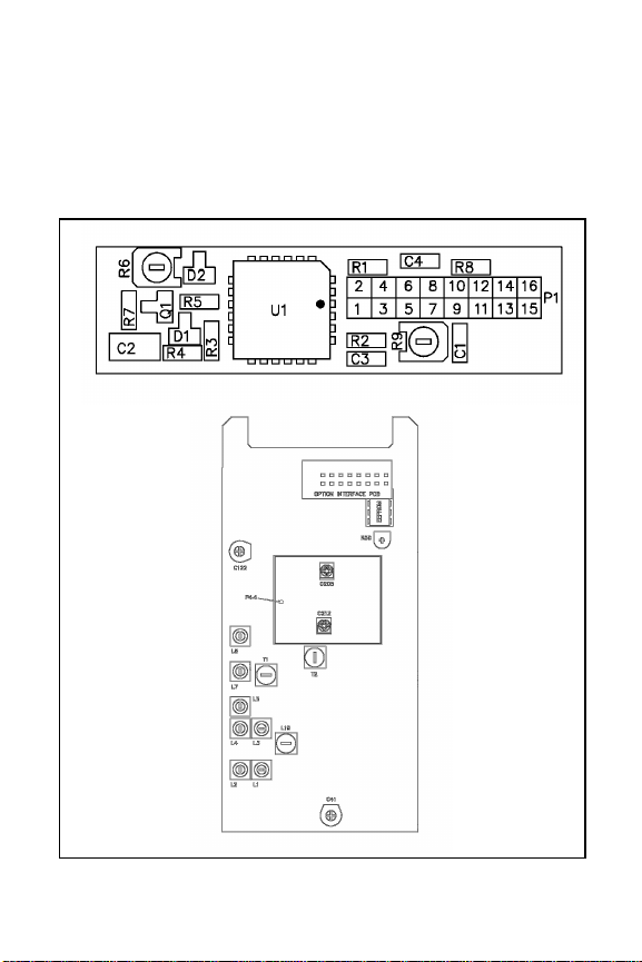
Channel Guard must be adjusted. Refer to Figure 2 for
alignment locations referenced in the following
procedures.
Monogram
Series Model MGP 300 Low Band
WARNING
Any repairs or adjustments should be made by a qualified
service technician or an authorized service center.
Suggested Test Equipment
The following, or its equivalent, is required for proper
alignment of the low band portable.
1. RF watt meter
2. Regulated power supply capable of 9 to 16 volts
adjustable; at least 2-3 ampere capacity.
3. FM Communications Monitor
4. EEPROM Programmer (MHTS3R)
5. SINAD meter
6. Oscilloscope
7. AC/DC voltmeter with a minimum of 1 megohm input
impedance
20
Page 21

Pre-Alignment Notes
1. The transmit frequencies should be within a 2 MHz
range.
2. The receive frequencies should be within a 2 MHz
range.
3. There is no constraint on the relationship between the
transmit frequencies and the receive frequencies
exceptthat they lie within the limits of the radio band
(i.e., 30-35, 35-42 or 42-50 MHz).
EEPROM PROGRAMMING
Before alignment, the radio must be programmed to the
user's transmit and receive frequencies as well as the
optional Channel Guard tone frequencies. This
programmed information is stored in a plug-in EEPROM
inside the radio unit. Use the procedure for the EEPROM
Programmer to program the EEPROM with the operating
information. The following procedure is used for removing
and re-installing the EEPROM in the radio unit.
1. Use a screwdriver or coin to unlatch the back cover
screw, located on the bottom of the radio, to remove
the battery cover. Rotate latch screw counterclockwise
to release.
21
Page 22
2. Remove the battery pack from the battery
compartment.
3. Locate the six screws holding the case together and
remove screws.
Figure 2 - Alignment Points
22
Page 23

4. With the battery compartment facing up, snap the case
halves apart.
5. Locate and carefully remove the optional Channel
Guard printed circuit board (see Figure 2 for location).
6. Locate and carefully remove the EEPROM.
7. Program the EEPROM to the user's operating
configuration.
8. Carefully re-install the EEPROM and reassemble
radio in the reverse order of the preceding steps 5 and
4.
TRANSMITTER ALIGNMENT
1. Connect a regulated power supply to the battery
terminals of the radio (battery removed). Set power
supply voltage for 10.8 VDC as measured at radio
battery terminals.
2. Connect an RF watt meter to the antenna jack.
3. Select the middle programmed transmit channel. Key
the transmitter and adjust C212 on the VCO printed
circuit board for 4.5 ±0.1 VDC at the control voltage
test point P4-4.
4. Select a programmed mid-frequency transmit channel.
Key the transmitter and adjust C122 for the correct
channel frequency ±100 Hz.
23
Page 24

5. Key the transmitter and adjust C41 for maximum RF
power output. Switch the radio between the highest
and lowest transmit frequencies and adjust C41 to
obtain the least power output variation across the
transmit frequency range.
6. Apply an audio frequency of 1 kHz at an output of
300 mVRMS (600 ohms source impedance) to the
EXT MIC/PTT/CHG jack. Key the transmitter and
adjust R50 for ±4.5 kHz deviation. Maintain the level
at 300 mV and sweep the audio frequency from 300 to
3000 Hz and readjust R50, if necessary, to ensure that
the deviation never exceeds ±5.0 kHz. Check all
programmed transmit channels and readjust R50, if
necessary, to ensure that the deviation does not exceed
±5.0 kHz.
7. If the optional Channel Guard tone board is installed
and any transmit channel is programmed for Channel
Guard operation, the Channel Guard tone deviation
must be set. Key the transmitter on the selected
channel and adjust R9 on the Channel Guard board for
±0.75 kHz deviation.
RECEIVER ALIGNMENT
1. Select the middle programmed receive channel and
adjust C205 on the VCO printed circuit board for 4.5
±0.1 VDC at P4-4.
2. Turn the SQuelch control fully counterclockwise but
do not turn into the detent (tone) position.
24
Page 25

3. Connect oscilloscope (and distortion analyzer, if
available) across the speaker terminals.
4. Select a programmed mid-frequency receive channel.
Apply a 1000 Hz tone at 3 kHz deviation at 1 mV on
the receive channel frequency to the antenna jack.
5. Adjust the discriminator coil L19 for maximum sine
wave amplitude at the speaker terminals. Adjust
VOLUME control, if necessary, to prevent clipping. If
a sine wave is not visible (only noise), perform Step 8
then return to this step.
6. Adjust T1, T2 and L19 for lowest audio distortion at
the speaker terminals.
7. Connect a SINAD meter across the speaker terminals.
Adjust the VOLume control to the proper level for the
SINAD meter. Adjust the input from Step 4 until
SINAD meter indicates 12 dB SINAD.
8. Adjust L1, L2, L3, L4, L5, L7, L8 and T1 for the best
sensitivity while readjusting the input level to keep the
SINAD meter reading near 12 dB SINAD.
9. Repeat Step 8 with the highest and lowest
programmed receive channels, if necessary to give the
best sensitivity across the receive band.
10. If the radio is equipped with the optional Channel
Guard encode/decode board and the radio is
programmed for receive Channel Guard, adjustments
must be made to the Channel Guard circuitry.
25
Page 26

11. Adjust input to receiver for a reading of 10 dB SINAD
on the SINAD meter.
12. Rotate the SQuelch control fully counterclockwise
until it goes into the detent (tone) position. This
enables the tone decoder.
13. Monitor U1-13 and adjust R6 until the voltage just
goes high (more than 2.5 VDC). Remove the RF
signal input and verify that U1-13 goes low (less than
2.5 VDC). This sets the noise squelch threshold to 10
dB SINAD to prevent noise falsing.
14. Check tone decoder operation by modulating the RF
input with the selected Channel Guard tone for the
receive channel under test at 750 Hz deviation. The
receiver should unsquelch and the 1000 Hz audio
signal should be heard.
ANTENNA TUNING
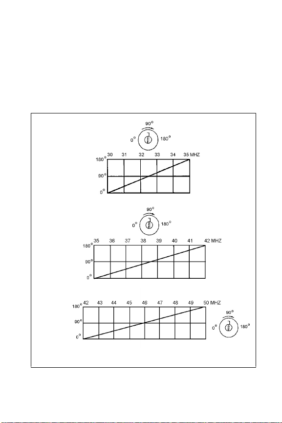
Refer to Figure 3 for tuning capacitor setting for the
various frequencies. To tune the antenna perform the
following steps:
1. Remove slotted set-screw from coil cover of antenna
to uncover the tuning capacitor.
2. Select the channel of the radio that represents the
center of the frequencies programmed.
3. Hold the radio upright and press the PTT bar to key
the transmitter on the selected channel.
26
Page 27
4. With a field strength meter in the same polarization
plane as the radio antenna, use a non-conductive
tuning tool to adjust the tuning capacitor for maximum
field strength.
5. After tuning, carefully re-install the set-screw into the
coil cover until it is flush with the outside of the coil
cover. DO NOT OVER TIGHTEN.
Figure 3 - Antenna Tuning Capacitor Settings Vs
Frequencies
27
Page 28

NOTES
28
Page 29

NOTES
29
Page 30

NOTES
30
Page 31
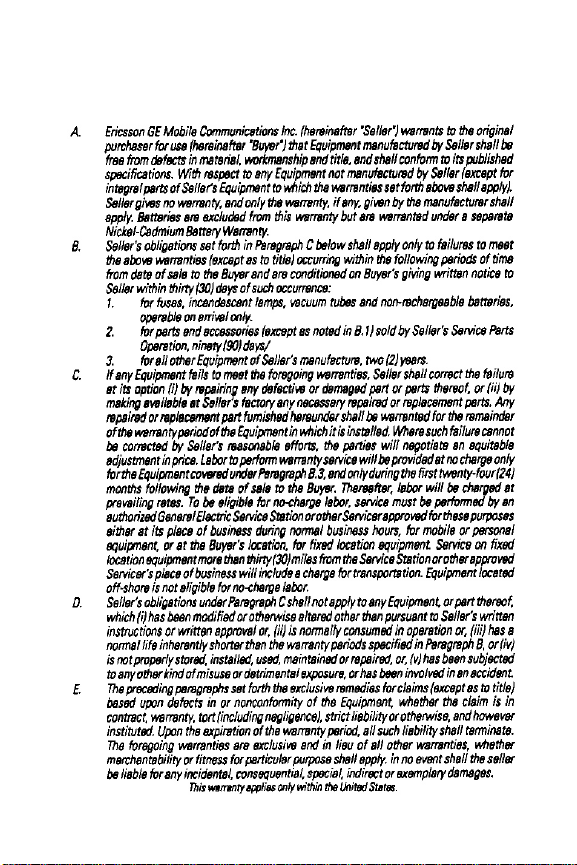
MONOGRAM SERIES WARRANTY
31
Page 32

Police
State Police
Fire
Poison Control
Ambulance
Life Saving and
Rescue Squad
EMERGENCY NUMBERS
Ericsson GE Mobile Communications Inc.
Mountain View Road • Lynchburg, Virginia 24502
32
Printed in U.S.A.
 Loading...