

Page 1
Mobile Communications
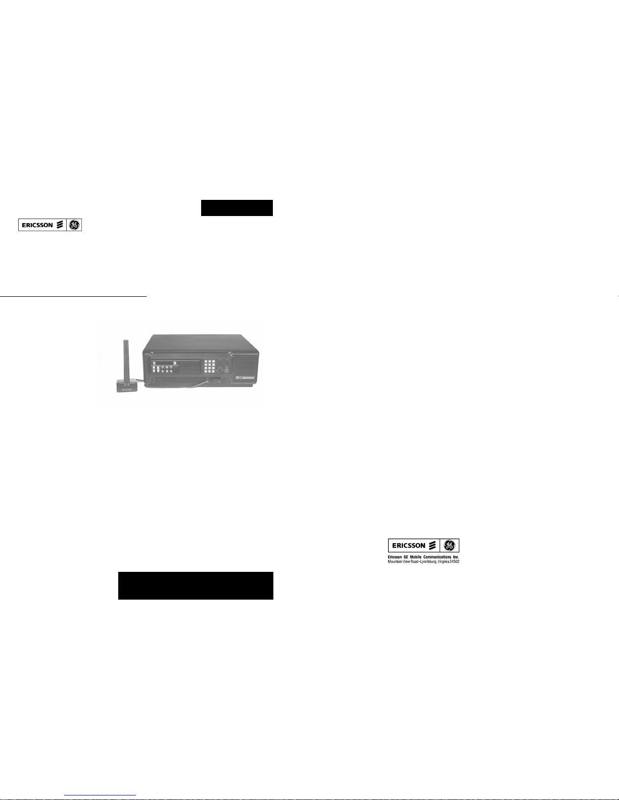
MDX Desk Top Station
Installation Manual
LBI-38977B
Printed in U.S.A
Page 2
INTRODUCTION
This manual contains instructions for the assembly of an
Ericsson GE Desk Top Station. This is done by installing an
MDX mobile radio into the Desk Top Station Assembly, using
the hardware kit supplied.
Ericsson GE Mobile Radios which can be accommodated
by the Desk Top Station are MDX Conventional/EDACS Radios in the 800 and 900 MHz bands.
Included are mounting instructions for the radio, as well as
instructions for making the few required cable connections.
Installation is made easy with the help of an Installation Diagram and an Interconnection Diagram, included as part of this
manual.
UNPACKING AND CHECKING
EQUIPMENT
Hardware Kit 349A9526 was used to assemble your station. The unused material was shipped with the station. Remove the kit and store for possible use.
Copyright© September 1993, Ericsson GE Mobile Communications Inc.
Installation of the Ericsson GE Desk Top Station includes
three parts:
1. Installation of the Mobile Radio in the Desk Top Station Assembly using Hardware Kit 349A9526 (supplied).
2. Installation of Option Boards in the Desk Top Station
Assembly, in accordance with options selected. Remote Interface Board Option, with one of the following remote boards:
a. DC Remote Board
b. 4-Channel Tone Remote Board
c. 5-Channel EDACS Tone Remote Board
d. Standby Power Transfer Option
3. Installation of the Ericsson GE Desk Top Station in
the place of operation with the necessary power, antenna, microphone, and line connecti ons.
INSTALLATION
PREPARATION OF DESK TOP STATION
1. Loosen the two (2) captive screws which hold the
top cover on the Desk Top Assembly. Remove the
cover.
2. Disconnect cable W2 from J202 on the Interconnect board.
3. Loosen,
Do Not Remove, the two (2) M3.5 screws
that hold the radio mounting bracket on the Desk
Top Station Assembly.
4. When external wires for options are to be connected, remove and discard the round knockout
button in the rear of the station housing. Insert the
rubber grommet 5490407P10 in the hole. Place the
cable clamp (344A3480P1) around the wires. Snap
the cable clamp retainer into the hole adjacent to
the grommet.
PREPARATION OF MOBILE RADIO
1. Remove the bottom cover of the radio by removing
the four (4) retaining TORX
®
screws.
2. Unplug the radio internal speaker cable from J904
on the radio and let it hang.
3. Discard the rubber plug and in its place slip the
rubber sleeve on cable W2. P905 of W2 plugs into
J905.
4. Replace the bottom cover of the radio with the four
(4) retaining TORX
®
screws removed in Step 1.
5. Using a permanent marker, copy the FCC identification number of the radio onto the Desk Top Station FCC label.
6. Attach the side mounting brackets with four (4) hex
mounting screws (2 per side) in the sides of the radio.
INSTALLING THE MOBILE RADIO
1. Connect P202 of cable W2 from the radio to J202
on the Interconnect Board.
2. Connect P101 of the Desk Top Station antenna cable W1 into J101 on the radio.
3. Connect P1 of the Desk Top Assembly power cable
W3 to J1 of the radio power cable W901.
4. Place the radio in the mounting bracket and position it for the proper Desk Top Station front appearance and tighten the two (2) M3.5 screws that hold
the radio mounting bracket in place.
5. Replace the Desk Top Assembly cover using the
two (2) screws loosened in Step 1 of "PREPARA-
TION OF DESK TOP STATION."
This completes the installation of the mobile radio in the
Desk Top Station Assembly.
INSTALLING THE DESK T OP STATION
AC Power
The Desk Top Station power supply must be connected
to AC power with the fused and ON/OFF-switched AC
power cable found at the back of the Desk Top Assembly.
The transformer straps are shipped set for a 120 volt power
source:
120volts ±10%, Single-Phase, 50/60 Hz, 4 amps,
500 watts
Refer to Power Supply Maintenance Manual LBI-38751
for procedures to change the transformer straps to accommodate a 240 volt power source:
240volts ±10%, Single-Phase, 50/60 Hz, 2 amps,
500 watts
Microphone
A desk microphone, a DTMF microphone, or a standard
mobile microphone can be used. The microphone connects
to the Desk Top Station at J101 on the Front Cap under the
Control Panel.
Antenna
A 50-ohm antenna is required. It should be connected
through coax cable to the Type N connector mounted in the
rear wall of the Desk Top Assem bly.
TABLE OF CONTENTS
Page
INTRODUCTION . . . . . . . . . . . . . . . . . . . . . . . . . . . . . . . . . . . . . . . . . . . . . . . . . . . . . 1
UNPAC KING AND CHECKING EQUIPMENT . . . . . . . . . . . . . . . . . . . . . . . . . . . . . . . . . . . . 1
INSTALLATION . . . . . . . . . . . . . . . . . . . . . . . . . . . . . . . . . . . . . . . . . . . . . . . . . . . . . 1
PREPARATION OF DESK TOP STATION . . . . . . . . . . . . . . . . . . . . . . . . . . . . . . . . . . . . 1
PREPARATION OF MOBILE RADIO . . . . . . . . . . . . . . . . . . . . . . . . . . . . . . . . . . . . . . . 1
INSTALLING THE MOBILE RADIO . . . . . . . . . . . . . . . . . . . . . . . . . . . . . . . . . . . . . . . 1
INSTALLING THE DESK TOP STAT IO N . . . . . . . . . . . . . . . . . . . . . . . . . . . . . . . . . . . . . 1
INSTALLING THE STANDBY POWER TRANSFER OPTION . . . . . . . . . . . . . . . . . . . . . . . . . 2
INSTALLING THE REMOTE OPTION . . . . . . . . . . . . . . . . . . . . . . . . . . . . . . . . . . . . . . 2
ADJUSTING THE REMOTE OPTION . . . . . . . . . . . . . . . . . . . . . . . . . . . . . . . . . . . . . . 2
INSTALLING THE KEYPAD BOARD OPTIO N . . . . . . . . . . . . . . . . . . . . . . . . . . . . . . . . . 2
DIAGRAMS
INSTALLATION INSTRUCTIONS . . . . . . . . . . . . . . . . . . . . . . . . . . . . . . . . . . . . . . . . . . . 3
INTERCONNECTION DIAGRAM . . . . . . . . . . . . . . . . . . . . . . . . . . . . . . . . . . . . . . . . . . . 15
The Desk Top Station may not operate prope rly with
the antenna mounted near the radio. Always mount
the antenna at least five (5) feet from the station.
CAUTION
LBI-38977 LBI-38977
1
Page 3
INSTALLING THE STANDBY POWER
TRANSFER OPTION
1. Loosen the two (2) captive screws holding the top
cover on the Desk Top Station Assembly and remove the cover.
2. Disconnect cable W3 from the station power supply
at J1/P101.
3. Mount Power Transfer Relay K1 inside to the side
wall between the power supply and speaker using
the single mounting screw supplied.
4. Remove and discard the rectangular knockout button in the rear wall of the Desk Top Assembly.
Snap P2 of BATT STBY/PWR cable into the hole.
5. Connect the relay har ness as f o llows:
a. Connect P1 to J1 of the station power supply.
b. Connect J1 to P1 of W3.
6. Replace the Desk Top Assembly cover using the
two screws loosened in Step 1 of these instructions.
INSTALLI NG THE REMOTE OPTION
1. Remove the two (2) hex screws holding the top
cover on the Desk Top Station Assembly. Remove
the cover.
2. If the Desk Top Assembly already includes the factory installed "Intercom Remote" Control Panel and
the Remote Interface Board, proceed to Step 6 below. Otherwise, replace the standard Control Panel
with the "Intercom Remote" control panel.
3. Remove jumper P104 from J204 on the Interconnect Board. Install the Remote Interface Board.
4. Mount the Remote Interface Board onto the Interconnect Board, plugging it in so P204 and P205
seat directly on the horizontally oriented pins of
J204 and J205 on the Remote Interface Board.
5. Remove and discard cables included with the Remote Board. Install the Remote Board on the base
of the station behind the Interconnect board on
standoffs with M3.5 screws. Connect the Remote
Board J2 to the Remote Interface Board J302 using
cable W7.
6. Connect the Remote Interface Board J301 to the
Control Panel J1 using cable W6.
7. Remove the knockout on the rear of the station for
J11. Insert J 11 of cabl e W10. Conne ct the other end
of W10 to J1 or TB1 of the Remote Board per the Interconnect Diagram 19D904375 sheet 2.
8. Adjust operating audio levels on the Remote Board
DC Remote Board 19A704686P3 LBI-31594
Tone Remote Board 19A704686P6 LBI-31552
EDACS Remote Board 19A704686P8 LBI-38119
The Remote Control Board should be checked
and adjusted when the system is installed. The tone
decoder and filter adjustments are set at the factory
and should not require adjustment unless the tone
filters, decoders, gene ra tors or a ssociated circuitry
are replaced.
Make sure all connections to the base station and
Remote Controller are complete, and that the tone
panel and base station have been properly aligned
before adjusting the To ne Rem o te C ontrol Board.
ADJUSTING THE REMOTE OPTION
Equipment Required
1. Ac voltmeter with dBm scale
2. Audio Generator
3. Deviation Monitor
Receive Audio (R2) (R35) (R66)
1. Apply a 1000 Hz to n e w i th a ± 3 kHz deviation
to the station receiver that is strong enough to fully
quiet the receiver.
2. A. On the DC Remote Bo ard 686P3 set R2 for 0dBm
at J1-1 & J1-4.
B. On the Tone Remote Board 686P6 set R35 for
0dBm at J1-3 & J1-4.
C. On the EDACS Remote Board 686P8 set R66 for
0dBm at TB1-2 & TB1-5.
Tx Mic Audio (R1) (R60) (R82)
1. Apply a 1000 Hz tone at 120mV into the microphone
jack of the Remote Controller with the largest lin e
loss (usually farthest from the station).
2. A. On the 686P3 DC Remote Board set R1 for the
proper deviation.
B. On the 686P6 Tone Remote Bo ard set R60 for the
proper deviation.
C. On the 686P8 PST Remote Board set R82 for the
proper deviation.
For detailed instructions, refer to the applicable maintenance manual for the board being adjusted. T h e a udio lev els
on the Remote Board must be adjusted first, before the two intercom level adjustments can be made on the Remote Interface
Board.
Speaker Level
1. After the Remote Board is set up so that the remote
consoles are transmitting and receiving properly with
the Desk Top Station radio, adjust the intercom levels
on the Remote Interface Boar d :
a. Adjust R323 for the proper remote console
speaker level from the station desk microphone.
b. Adjust R325 for the proper station speaker level
from the remote console microphone.
2. Replace the Desk Top Assembly cover with the two
(2) screws loosened previously.
INSTALLING THE KEYPAD BOARD OPTION
1. Loosen the two (2) captive screws holding the top
cover on the Desk Top Station Assembly. Remove
the cover.
2. Mount the Keypad Board onto the Interconnect
Board, plugging it in so that P207 and P208 seat directly on the horizontally oriented pins of J207 and
J208 on the Interconnect Board.
3. Connect the end of W9 marked "keypad" onto the
keypad pins. Plug the other end onto J401 of the
Keypad Board. Observe keyed pins of W9.
4. When remote options are used, connect cable W8 to
P2 of the Remote Board. Connect the other end to
J401 of the Keypad Board. Orient plug at J402 so the
pin with no wire is toward J208.
5. On Remote Interface Board connect jumpers as follows:
P303 on J303 pins 2 and 3
P304 on J304 pins 2 and 3
P305 on J305 pins 2 and 3
P306 on J306 pins 2 and 3
P307 on J307 pins 2 and 3
6. Replace Desk Top Assembly cover with the two (2)
screws loosened in Step 1.
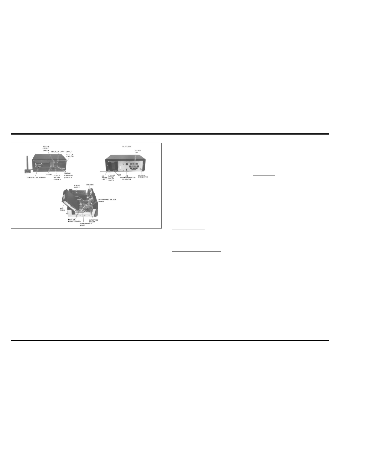
Figure 1 - Desk Top Station Assembly
LBI-38977 LBI-38977
2
Page 4
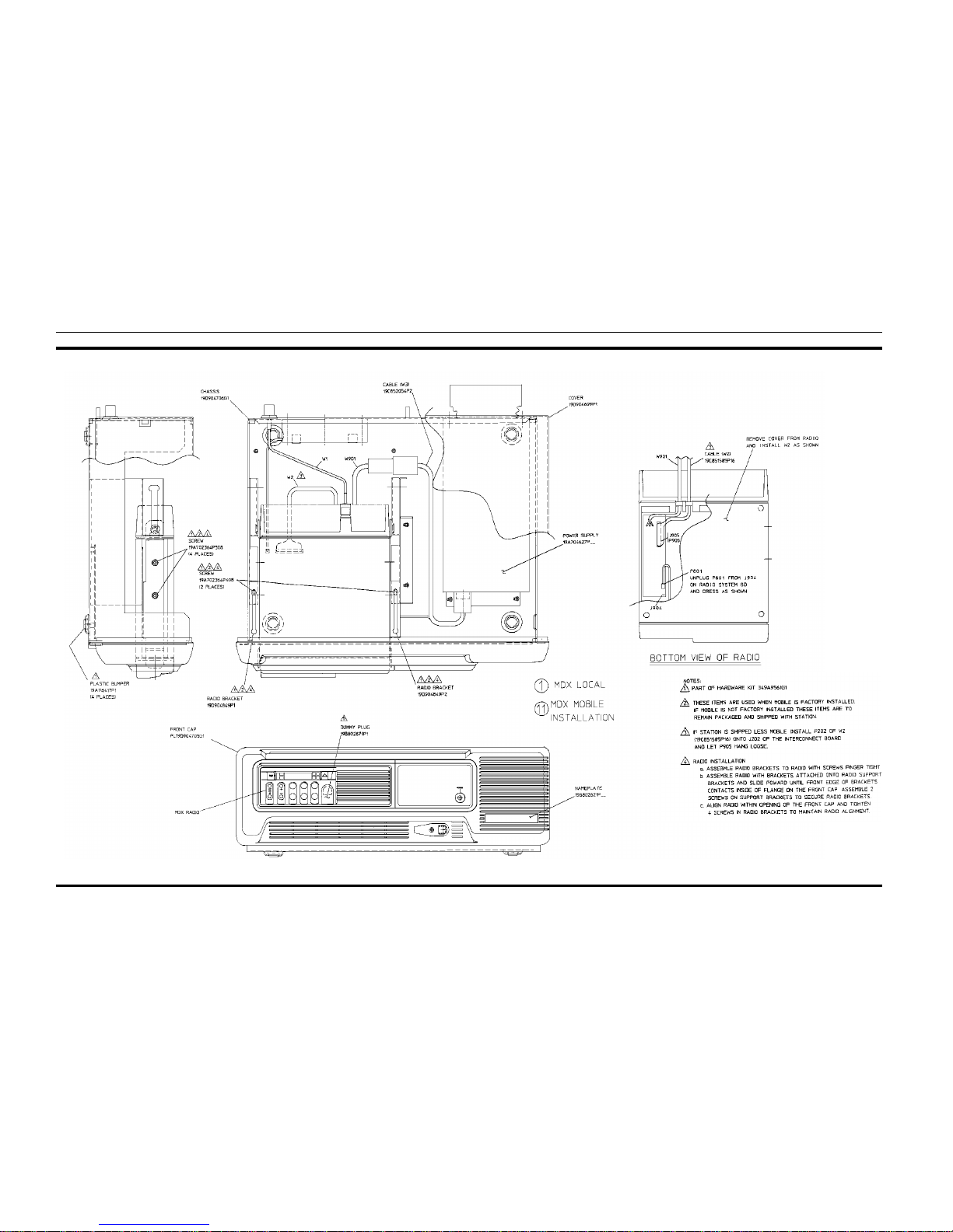
INSTALLATION INSTRUCTIONS
APPLICATION ASSEMBLY
MDX Mobile Installation
(19D904704, Sh. 1, Rev.1)
LBI-38977 LBI-38977
3
Page 5
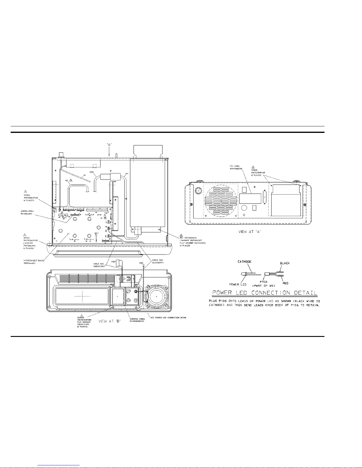
INSTALLATION INSTRUCTIONS
APPLIC ATION ASSEMB LY
MDX Mobile Installation (Cont’d from Sh.1)
(19D904704, Sh. 2, Rev.1)
LBI-38977 LBI-38977
4
Page 6
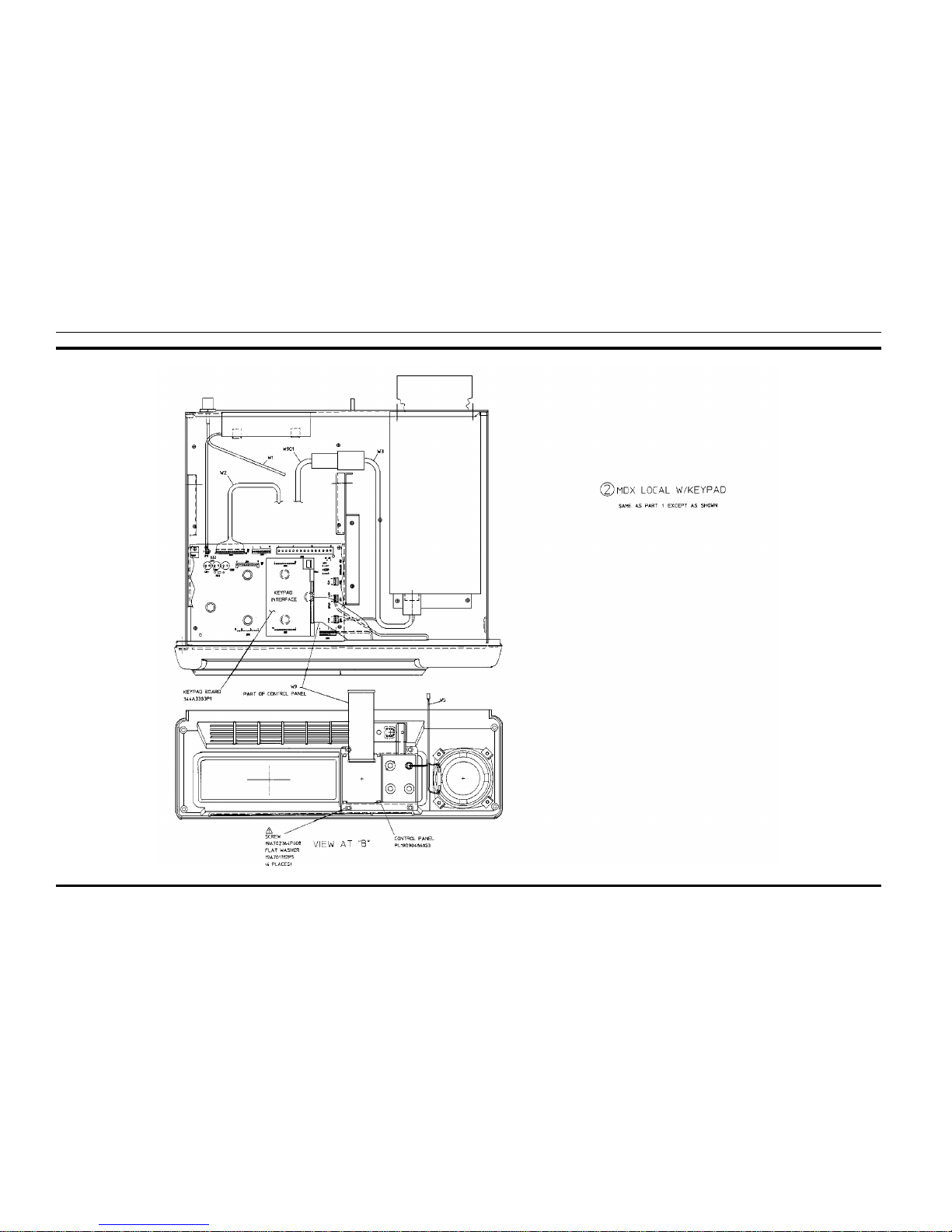
INSTALLATION INSTRUCTIONS
APPLICATION ASSEMBLY
MDX Local with Keypad
(19D904704, Sh. 3, Rev. 1)
LBI-38977 LBI-38977
5
Page 7
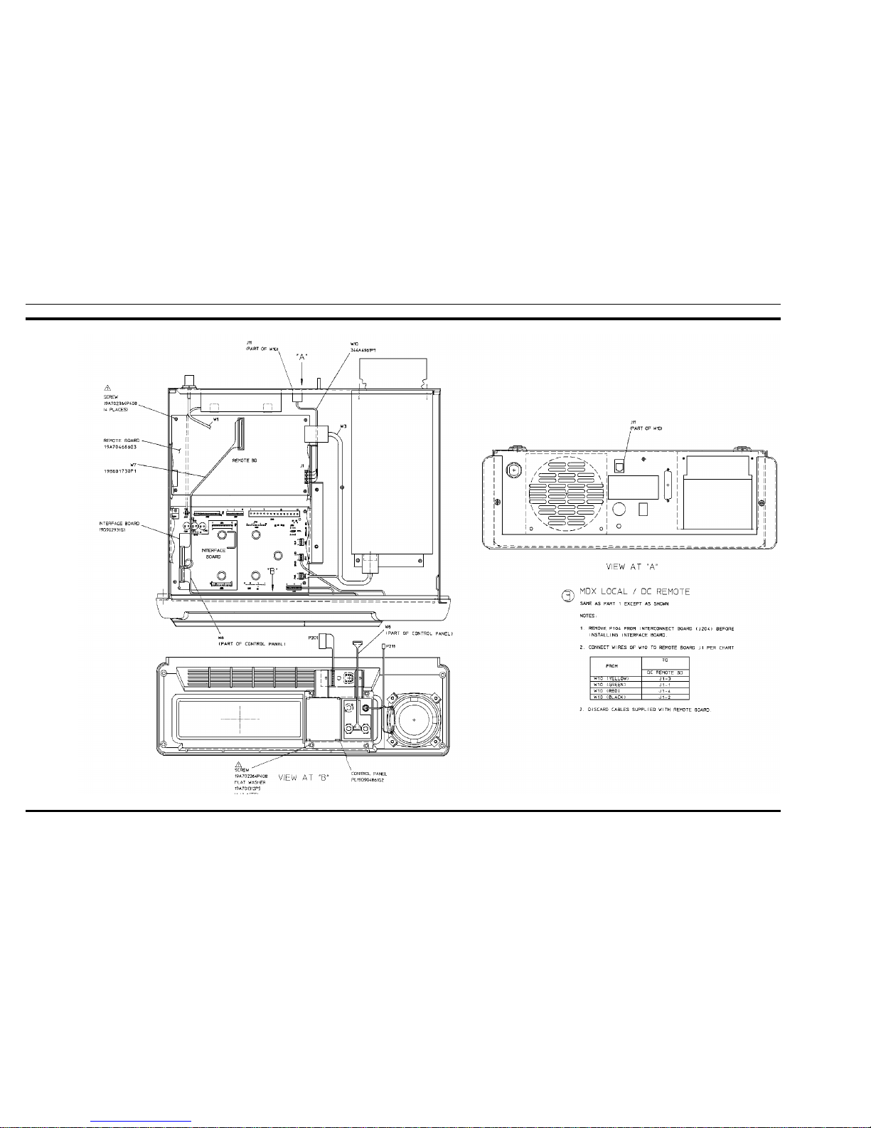
INSTALLATION INSTRUCTIONS
APPLIC ATION ASSEMB LY
MDX Local/ DC Remote
(19D904704, Sh. 4, Rev.1)
LBI-38977 LBI-38977
6
Page 8
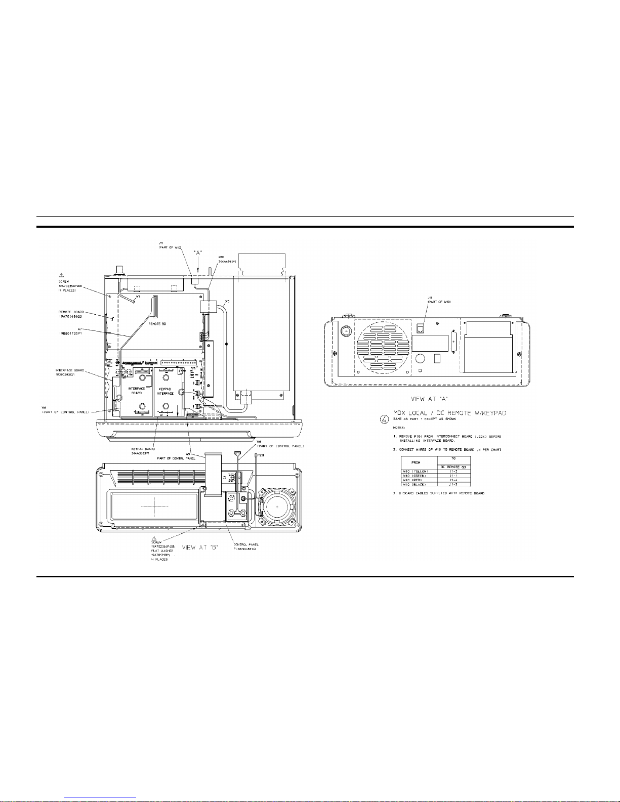
INSTALLATION INSTRUCTIONS
APPLICATION ASSEMBLY
MDX Local/DC Remote with Ke ypad
(19D904704, Sh. 5, Rev. 1)
LBI-38977 LBI-38977
7
Page 9
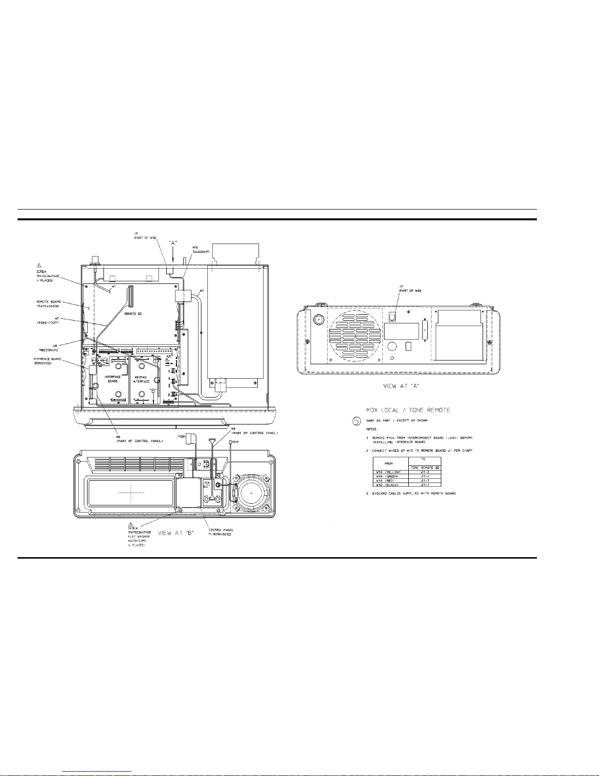
INSTALLATION INSTRUCTIONS
APPLIC ATION ASSEMB LY
MDX Local/Tone Remote
(19D904704, Sh. 6, Rev.1)
LBI-38977 LBI-38977
8
Page 10
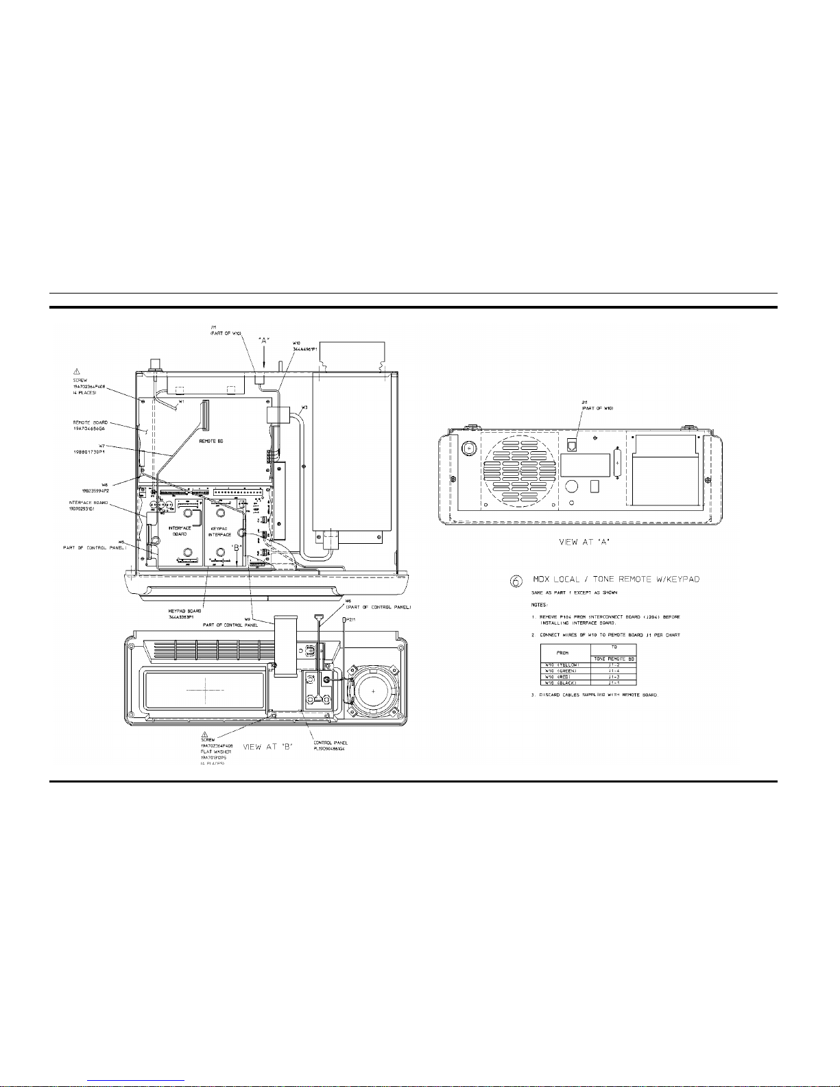
INSTALLATION INSTRUCTIONS
APPLICATION ASSEMBLY
MDX Local/Tone Remote with Keypad
(19D904704, Sh. 7, Rev. 1)
LBI-38977 LBI-38977
9
Page 11
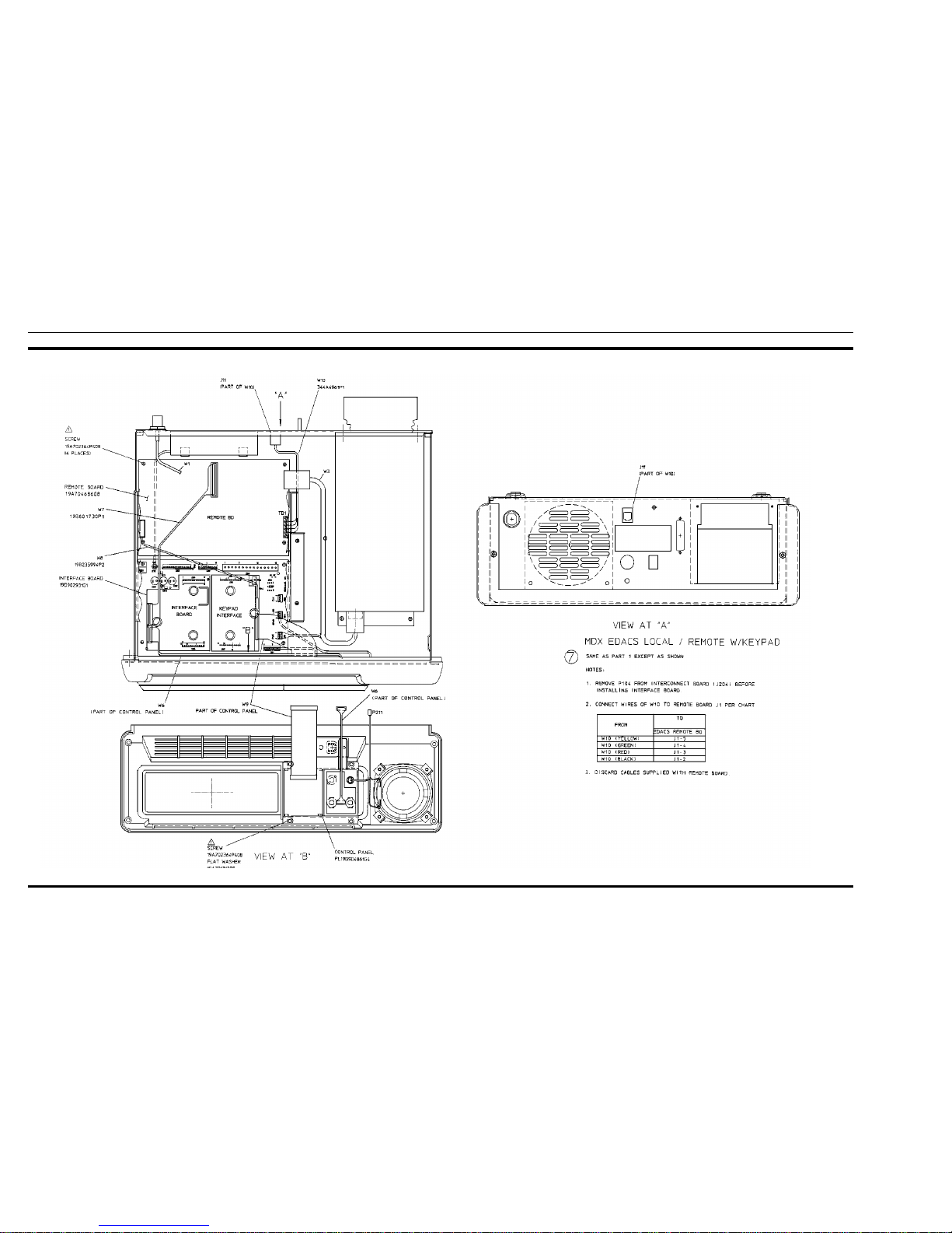
INSTALLATION INSTRUCTIONS
APPLIC ATION ASSEMB LY
MDX EDACS Local/Remote with Keypad
(19D904704, Sh. 8, Rev.1)
LBI-38977 LBI-38977
10
Page 12
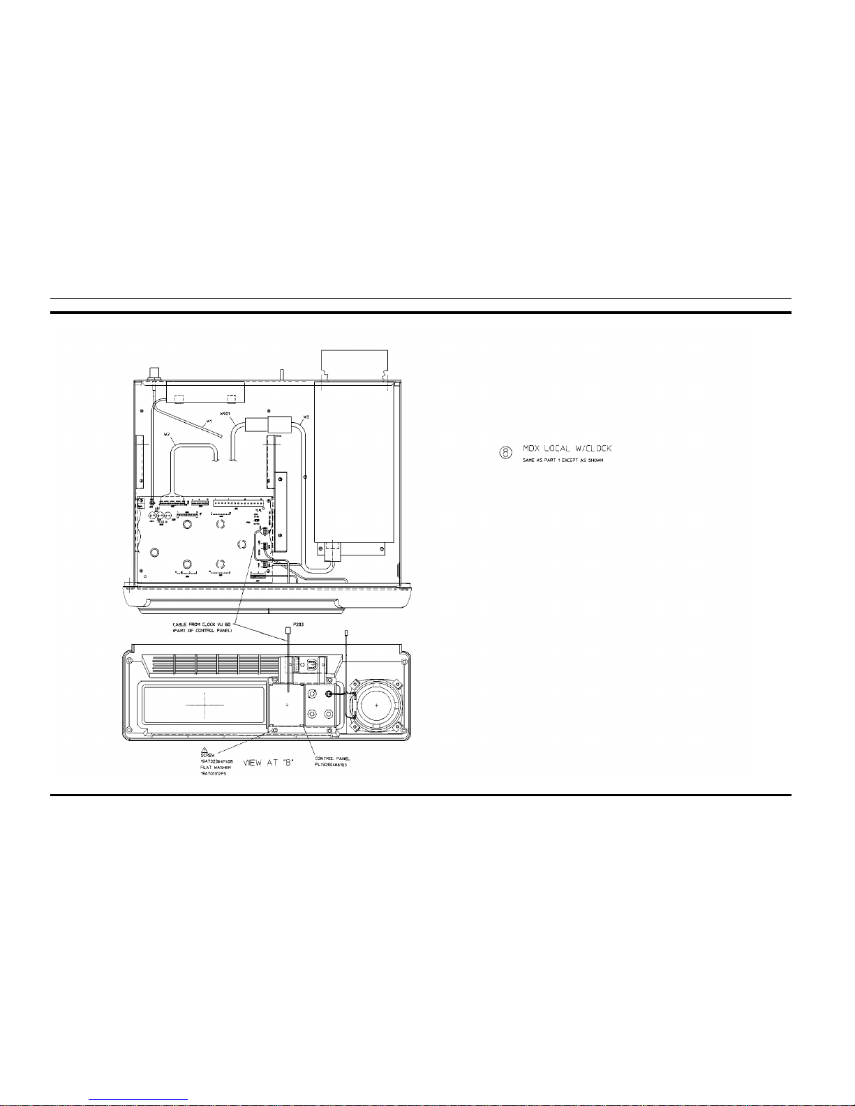
INSTALLATION INSTRUCTIONS
APPLICATION ASSEMBLY
MDX Local with Clock
(19D904704, Sh. 9, Rev. 1)
LBI-38977 LBI-38977
11
Page 13
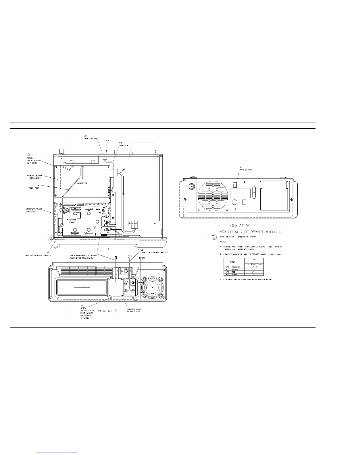
INSTALLATION INSTRUCTIONS
APPLIC ATION ASSEMB LY
MDX Local/DC Remote with Clock
(19D904704, Sh. 10, Rev.1)
LBI-38977 LBI-38977
12
Page 14
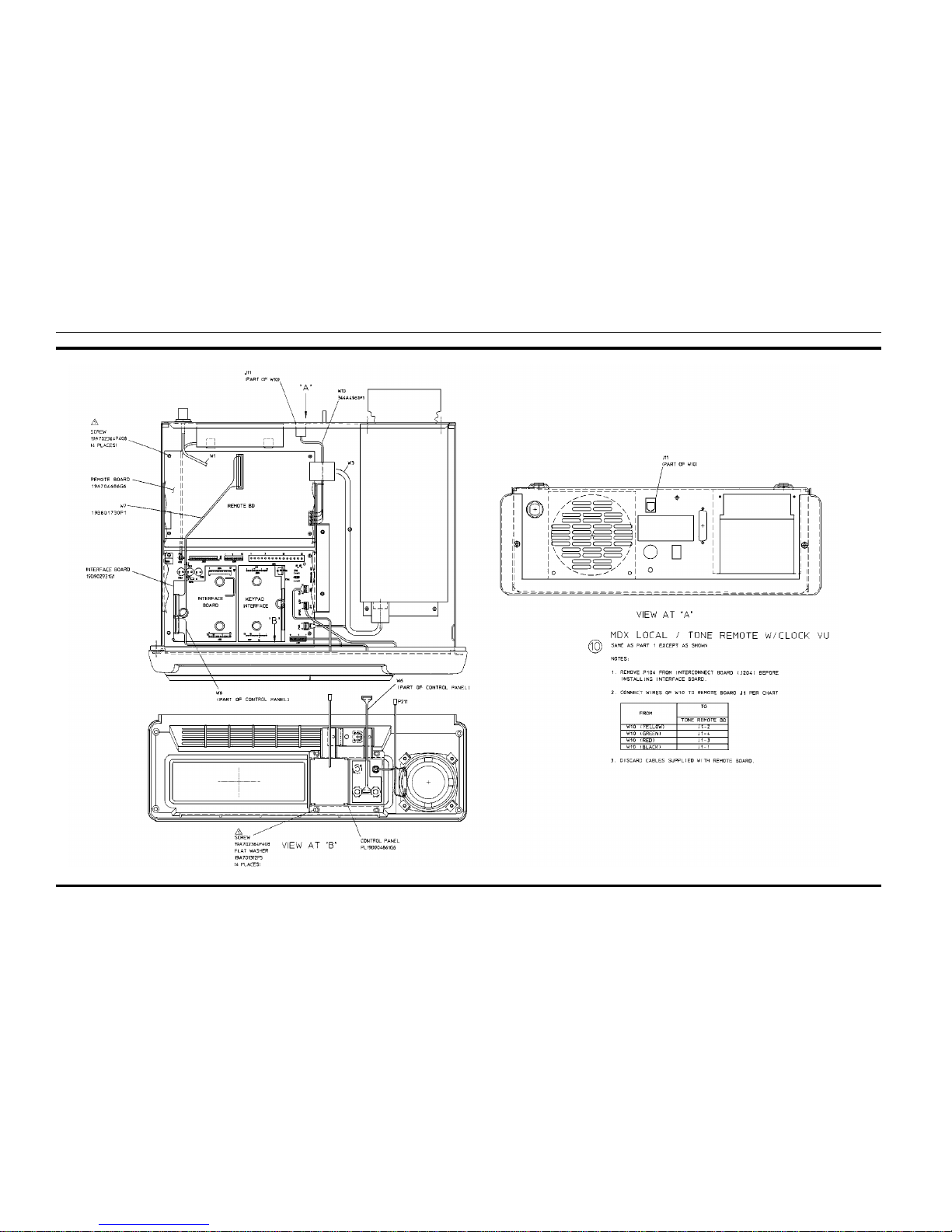
INSTALLATION INSTRUCTIONS
APPLICATION ASSEMBLY
MDX Local/To ne Remote wi th Clock VU
(19D904704, Sh. 11, Rev. 1)
LBI-38977 LBI-38977
13
Page 15
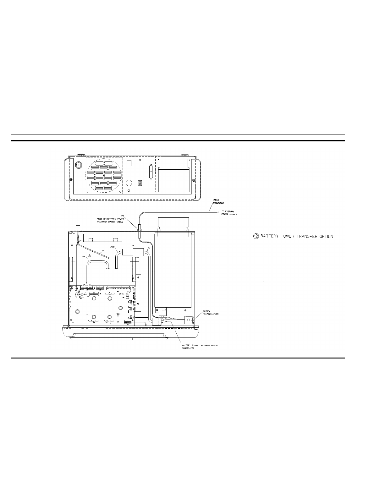
INSTALLATION INSTRUCTIONS
APPLIC ATION ASSEMB LY
Battery Power Transfer Option
(19D904704, Sh. 12, Rev.1)
LBI-38977 LBI-38977
14
Page 16
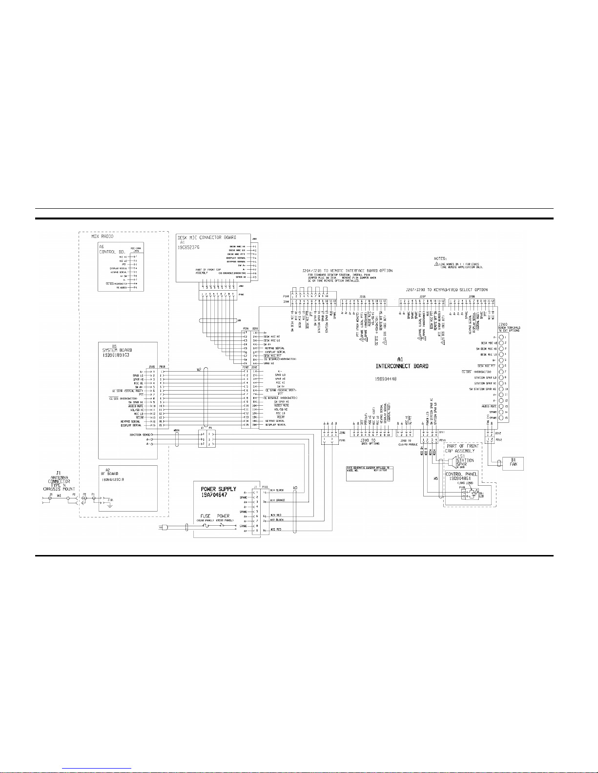
INTERCONNECTION DIAGRAM
Interconnect Board & Power Supply
(19D904375, Sh. 1, Rev. 1)
LBI-38977 LBI-38977
15
Page 17
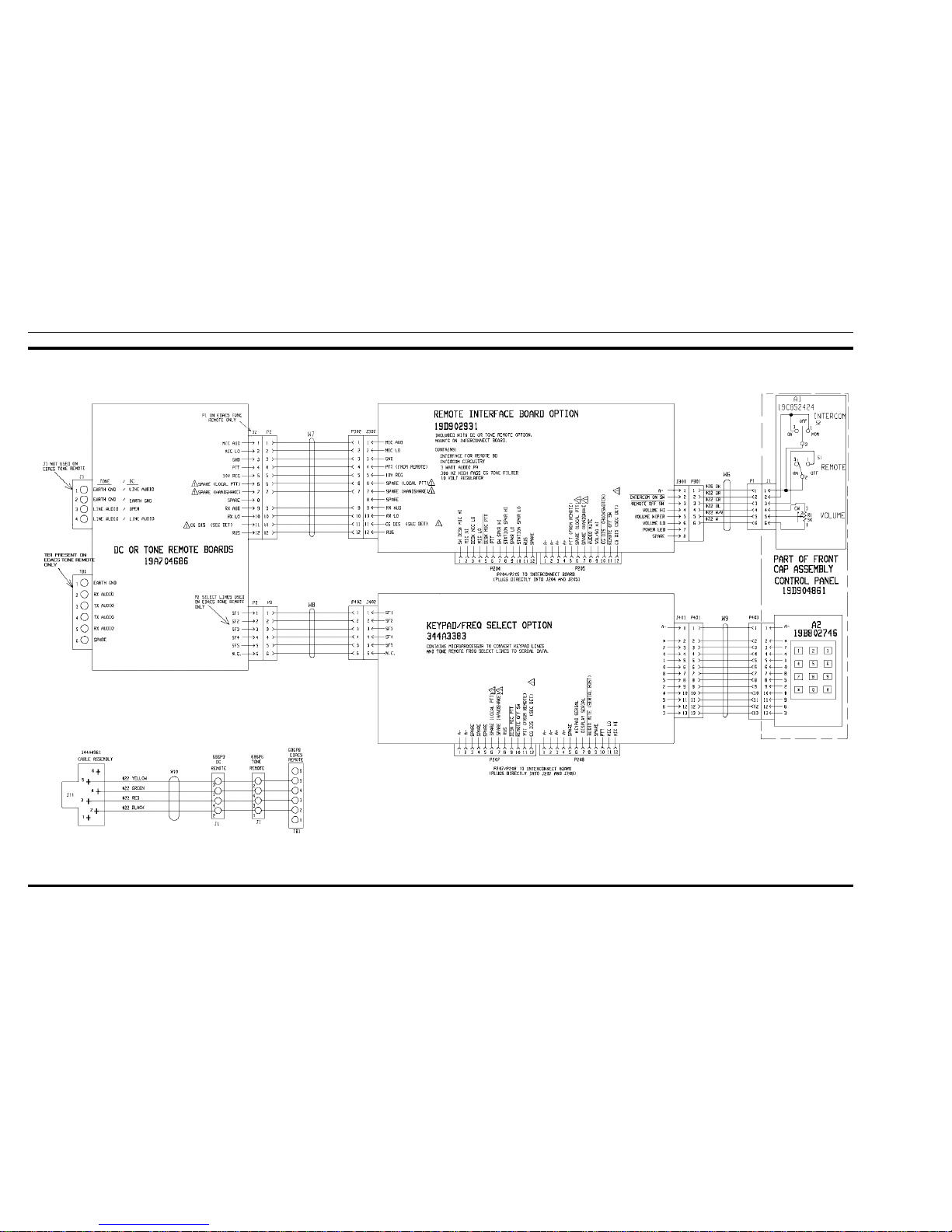
INTERCONNECTION DIAGRAM
Remote Interface Board Option, DC or Tone
Remote Option, and Keypad/Frequency Select Op tion
(19D904375, Sh. 2, Rev. 0)
LBI-38977 LBI-38977
16
Page 18

INTERCONNECTION DIAGRAM
Battery Power Transfer Option
(19D904375, Sh. 3, Rev. 1)
LBI-38977 LBI-38977
17
 Loading...