

Page 1
Mobile Communications
MDS
148-174 MHz MOBILE RADIO
COMBINATION
TABLE OF CONTENTS
MAIN BOARD ASSEMB LY . . . . . . . . . . . . . . . . . . . LBI-38756
FRONT PA NEL ASSEMB LY . . . . . . . . . . . . . . . . . . . LBI-38757
POWER AMPLIFIER ASSEMBLY . . . . . . . . . . . . . . . LBI-38758
SERVICE SECTION . . . . . . . . . . . . . . . . . . . . . . . LBI-38759
Maintenance Manual
LBI-38652
Printed in U.S.A.
Page 2

Copyright © April 1992, Ericsson GE Mobile Communications, Inc.
TABLE OF CONTENTS
Page
SPECIFICATIONS . . . . . . . . . . . . . . . . . . . . . . . . . . . . . . . . . . . . . . . . . . . . . . . . . . . . 1
PACKAGE NUMBERS . . . . . . . . . . . . . . . . . . . . . . . . . . . . . . . . . . . . . . . . . . . . . . . . . . 2
OPTIONS . . . . . . . . . . . . . . . . . . . . . . . . . . . . . . . . . . . . . . . . . . . . . . . . . . . . . . . . . 2
INTRODUCTION . . . . . . . . . . . . . . . . . . . . . . . . . . . . . . . . . . . . . . . . . . . . . . . . . . . . . 2
RADIO DESCRIPTION . . . . . . . . . . . . . . . . . . . . . . . . . . . . . . . . . . . . . . . . . . . . . . . . . 2
MAIN BOARD ASSEMBLY . . . . . . . . . . . . . . . . . . . . . . . . . . . . . . . . . . . . . . . . . . . . 2
FRONT PANEL ASSEMBLY . . . . . . . . . . . . . . . . . . . . . . . . . . . . . . . . . . . . . . . . . . . . 4
POWER AMPLIFIER ASSEMBLY . . . . . . . . . . . . . . . . . . . . . . . . . . . . . . . . . . . . . . . . 4
FEATURES . . . . . . . . . . . . . . . . . . . . . . . . . . . . . . . . . . . . . . . . . . . . . . . . . . . . . . . . 4
PC PROGRAMMABLE . . . . . . . . . . . . . . . . . . . . . . . . . . . . . . . . . . . . . . . . . . . . . . 4
EXTERNAL SPEAKER (Optional) . . . . . . . . . . . . . . . . . . . . . . . . . . . . . . . . . . . . . . . . . 5
BATTERY POWER . . . . . . . . . . . . . . . . . . . . . . . . . . . . . . . . . . . . . . . . . . . . . . . . . 5
EASY A CCESSIBILITY . . . . . . . . . . . . . . . . . . . . . . . . . . . . . . . . . . . . . . . . . . . . . . 5
SERVICE AIDS . . . . . . . . . . . . . . . . . . . . . . . . . . . . . . . . . . . . . . . . . . . . . . . . . . . . . . 5
DETAILED TYPE 99 OPERATION AND PROGRAMMING . . . . . . . . . . . . . . . . . . . . . . . . . . . . . 5
GE TYPE 99 FORMAT . . . . . . . . . . . . . . . . . . . . . . . . . . . . . . . . . . . . . . . . . . . . . . . 6
MOTOROLA FORMAT . . . . . . . . . . . . . . . . . . . . . . . . . . . . . . . . . . . . . . . . . . . . . . . 6
MECHANICAL PARTS BREAKDOWN . . . . . . . . . . . . . . . . . . . . . . . . . . . . . . . . . . . . . . . . 8
MECHANICAL PARTS LIST . . . . . . . . . . . . . . . . . . . . . . . . . . . . . . . . . . . . . . . . . . . . . . 9
FIGURES
Figure 1 - MDS Conventional Radio Block Diagram . . . . . . . . . . . . . . . . . . . . . . . . . . . . . . . . . . 3
TABLES
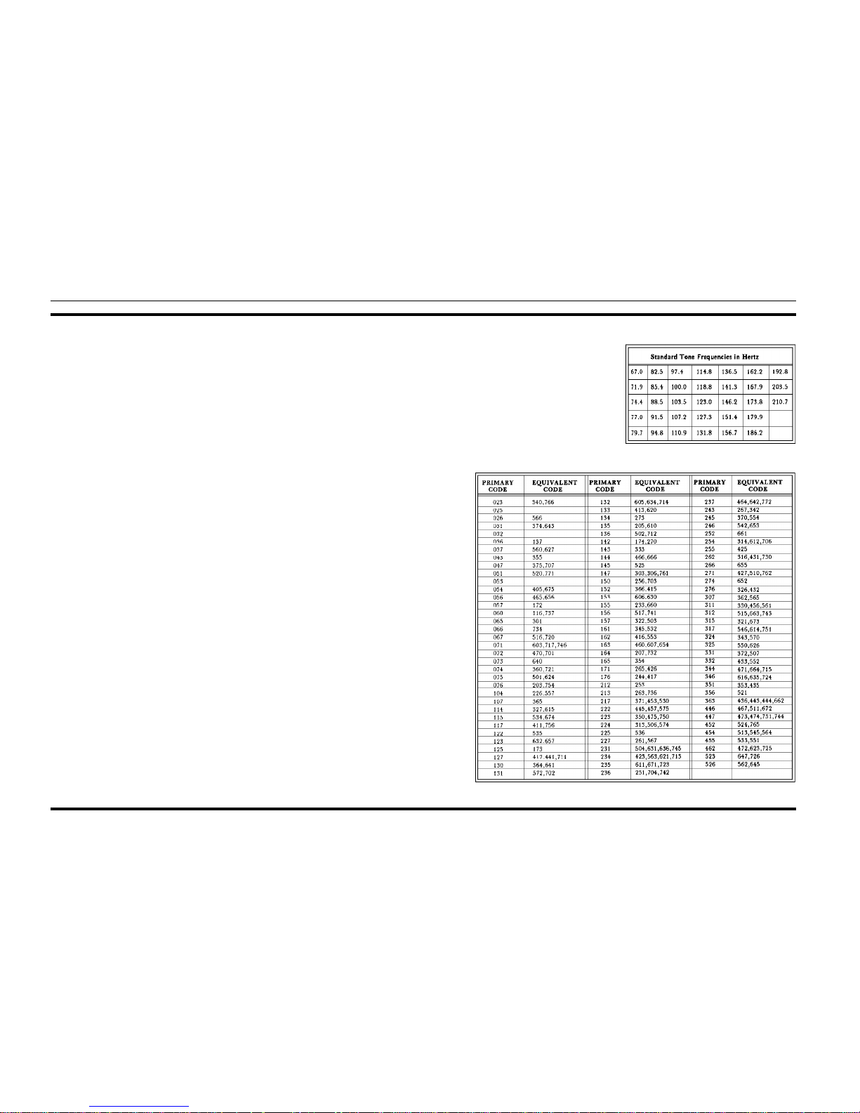
Table 1 - Channel Guard Tone Frequencies . . . . . . . . . . . . . . . . . . . . . . . . . . . . . . . . . . . . . . . . 5
Table 2 - Primary and Eq uival e nt Digital Codes (OCTAL) . . . . . . . . . . . . . . . . . . . . . . . . . . . . . . . . 5
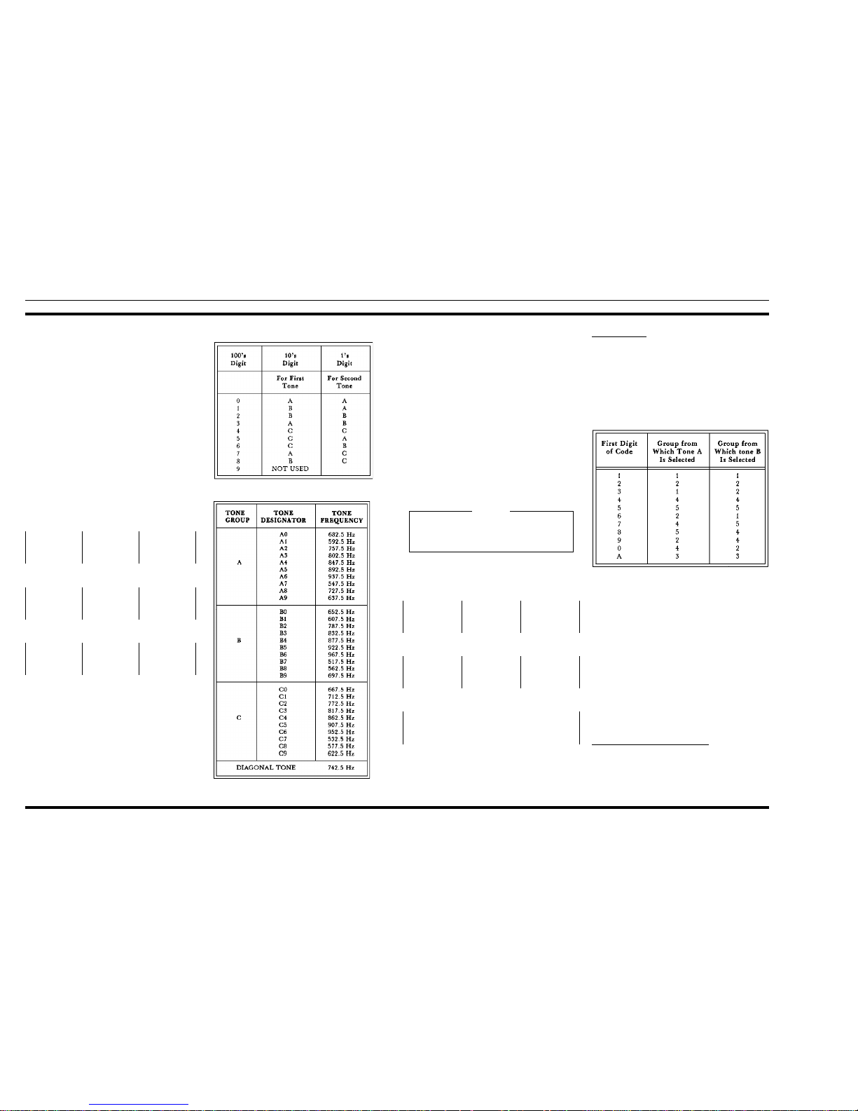
Table 3 - T o n e Groups . . . . . . . . . . . . . . . . . . . . . . . . . . . . . . . . . . . . . . . . . . . . . . . . . . . 6
Table 4 - Tone Generator Frequencies . . . . . . . . . . . . . . . . . . . . . . . . . . . . . . . . . . . . . . . . . . . 6
Table 5 - Motorola Type Coder Numb ers . . . . . . . . . . . . . . . . . . . . . . . . . . . . . . . . . . . . . . . . . 6
Table 6 - Motorola G roup C all Tone Groups (TG) . . . . . . . . . . . . . . . . . . . . . . . . . . . . . . . . . . . . 7
Table 7 - Motorola G roup C all Tone Groups (TG) . . . . . . . . . . . . . . . . . . . . . . . . . . . . . . . . . . . . 7
SPECIFICATIONS
GENERAL
Frequency Range Transmit: 148-174 MHz
Receive: Same as Transmit
Channel Spacing 25 kHz
Frequency Stability ±5.0 ppm
Operating Temperature Range -30 to +60°C
Battery Volta ge 13.6 volts ± 10% (meets specs)
± 20% (operational)
Radio Current Drain OFF: 0.01 amps
Rx Squelched: 0.9 amps
RxOn: 1.5 amps
Tx On: 10.0 amps
Size 170mm W x 216mm L x 53mm H
TRANSMITTER
Tx Two Frequency Spread 26 MHz
RF Power Output 40 watts (+ 146 dBm, Adjustable 20 to 40 watts)
Maximum Deviation ±5% kHz peak
Tx Duty Cycle 20% Intermittent (EIA)
FM Hum and Noise (EIA) -45 dBc maximum
Audio Distortion 5% @ 300 Hz, 3% @ 1kHz, 5% @ 3kHz
RF Load Impedance 50 ohms
Audio Sensitivity 80 mV ±3 dB
Audio Frequency Response Within + 1 ,-3 dB of a 6db/octave pre-emphasis,
300-3000 Hz (EIA)
Spurious Emissions
Conducted
Radiated
-16.5 dBm max (Meets DOC & FCC)
-13 dBm max (FCC)
RECEIVER
Receiver coverage
Factory Tuned
148-174 MHz
150-168 MHz
Rx Two Freq Spread 18 MHz (No degradation)
Channel Spacing 25/30 kHz
Sensitivity (12 dB SINAD) -117 dBm (.30 µV)
LBI-38652 LBI-38652
1
Page 3

INTRODUCTION
The Ericsson GE Conventional MDS VHF Radio is a rugged two-way FM mobile radio which operates in the 148-174
MHz frequency band. The MDS is a wide band synthesized radio utilizing microcomputer technology to provide reliable
high quality simplex two-way mobile communications. Its
transmitter output power level is 40 watts over the wide bandwidth of each split. The receiver has an allowable 12 MHz
maximum receive channel separation. There are two versions
available, a 2-channel and an 8-channel. The basic radio package includes the following fea t ure s :
• Microprocessor Control
• Synthesized RF Channel selection (frequency control)
• 7-Segment LED Channel Display
• Multi-tone Channel Guard (CTCSS) Encode/Decode
• Multi-code Digital Channel Guard (DCG)
Encode/Decode
• Automatic Hook Switch Channel Guard Disable
• Channel Activity S ensing (CAS)
• Carrier Control Ti m e r (CCT)
• 5 ppm frequency stability
• Type 99 Tone Decode
• Field Programmable with PC
• Fixed Squelch, threshold programma ble
• Internal 4-watt Speaker, with volume control
• Front Mounted Microphone Connector
• Rear Mounted Antenna TNC Connector
• Rear entry power connections
• ANI Encode
The small size of the MDS radio makes it ideal for front
mounting in conventional vehicles. The radio is operated with
a simple hand held microphone in combination with the following operating controls, all located on the front panel:
• Power ON/OFF Switch
• Channel UP/DOWN Selector
• Volume UP/DOWN Control
• Monitor Switch for Channel Guard Disable
• Type 99 To ne R ESET Switch, to reset the t one decoder.
Refer to the Operator’s Manual LBI-38651 for a complete
description of the operating procedures.
RADIO DESCRIPTION
MAIN BOARD ASSEMBLY
A sturdy aluminum casting houses the Main Board Assembly N29/85154001920. There is complete accessibility to the
Main Board with the radio’s top and bottom covers removed.
The Main Board contains the following circuits:
• Microprocessor and associated Logic
• Frequency Synthesizer
• Tran smi tter E x cite r
• Receiver
• Audio Processing (for both transmit and receive paths)
• Tone and Squelch Processing (for both transmit and
receive paths)
• Voltage Regulators
Logic Circuitry
The radio’s logic circuitry includes the 80C535 microprocessor with associated EPROM and Electrically Erasable
PROM (EEPROM) memory and latch circuitry. The Microprocessor controls the functions of the transmitter, the rec eiver,
the inputs from the operator and the outputs to the operator.
Synthesizer
A programmable Synthesizer generates both transmit and
receive operating frequencies. It includes a synthesizer chip, a
dual modulas counter, a temperature compensated reference
oscillator (TCXO) and a voltage controlled oscillator (VCO);
all part of an operating phase lock loop, with its requisite loop
filter.
Transmitter
The radio transmitter includes the Synthesizer’s modulated
VCO and the fixed tuned exciter amplifiers. T he e xc i te r a mplifiers are wideband, covering the VHF band without retuning.
The exciter output is fed to the Power Amplifier Board through
a coax cable. The exciter provides 35 dB of gain to drive the
Power Amplifier with 2 watts. The transmitter output level at
the antenna connector is factory set for a rated output power of
40 watts. The power control circuit detects the power output of
the Power Amplifier. Using the error signal, the power control
circuit varies the DC supply voltage to the first stage of the exciter. This will hold the transmitter output level c onstan t.
SPECIFICATIONS (Cont.)
Spurious Emissions
Radiated Meets FCC requirements
Conducted -57 dBm maximum
Rx Spurious Response 70 dB minimum
Adj Ch(2-Sig) Selectivity -75 dB max @ 30 kHz (EIA)
Intermodulation Attenuation -75 dB minimum
Rx Modulation Acceptance ± 7 kHz minimum
Audio Distortion 2% maximum @ 0.5 Watt (EIA)
10% maximum @ 4 Watts and 1 kHz
Audio Frequency Response Within + 2,-8 of a 6dB/octave de-emphases,
300-3000 Hz (EIA)
Rx Hum and Noise
Unsquelched -50 dB maximum
Squelched -70 dB maximum
Audio Output Power 4 watts, @ <10% Distortion
Speaker Impedance 4 ohms
MDS RADIO PACKAGE NUMBERS
PACKAGE NUMBER DESCRIPTION
TLH22 VHF 2 CHANNEL, 40 WATT
TLH28 VHF 8 CHANNEL, 40 WATT
OPTIONS
OPTION NUMBER DESCRIPTION
MC3G DESK TOP MIC
ANIR 1/4 WAVE, ROOF MT ANTENNA W/TNC CONNECTOR
ZM3L EXTERNAL WEATHERPROOF SPEAKER AND CABLE
LS1F MIL SPEC SPEAKER, 4 OHMS, 5 x 5
CD1E SPEAKER CABLE
PD1A NOISE FILTER KIT
SU1C ALARM RELAY KIT
EC1A DOC POWER SET
MA1L DESK TO P RADIO MOUN TING WEDGE
PS1D 240 VAC-12 VDC, 13A 50/60 Hz Power Supply
PS5K 120 VAC-12 VDC, 13A 50/60 Hz Power Supply
LBI-38652 LBI-38652
2
Page 4
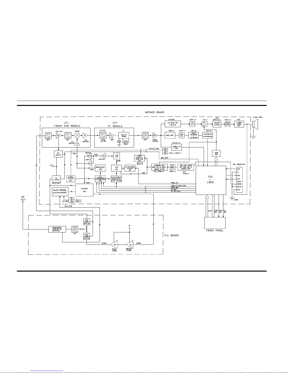
Figure 1 - MDS Conventional Radio Block Diagram
LBI-38652 LBI-38652
3
Page 5

Receiver
The RF front end of the receiver includes the PIN diode
T/R switch, the tuned bandpass preselector filters, and the
low noise RF amplifier. The filters have a 12 MHz bandwidth, and are factory tuned for receiving in the 150-162
MHz bandwidth. Refer to the Service Section LBI-38759 for
retuning to a different frequency. The first mixer (with its
low side injection from the VCO) generates a 45.000 MHz
IF signal which is filtered with monolithic crystal filte rs having a 15 kHz bandwidth. A 455 kHz low IF circuit module
contains the second local oscillator, the second mixer with
low side injection, external ceramic filters, an external
44.545 MHz crystal for the oscillator and the FM quadrature
detector circuit.
Transmit Audio Processing
In the transmit audio path, the audio from the microphone is passed through a 3 kHz low pass filter, preemphasized and hard limited for a maximum modulation peak
deviation of 4.5 kHz. A MIC Mute switch is controlled by
the logic as appropriate for tone or voice modulation of the
transmitter. Channel Guard tones and the A.N.I. signal from
the microprocessor are summed into the audio path before
the gain control. Next, a 3 kHz post limiter low p a ss filter attenuates frequencies above 20 kHz by more than 54 dB before passing the audio signal on to the modulation input of
the VCO.
Receive Audio Processing
Audio from the demodulator enters the voice path
through a 300 Hz high pass filter, followed by a 3 kHz low
pass filter. A "Rece ive Mute" switch is provided so t he v oice
signal can be muted by the microprocessor when it sums its
Alert tones into the path. The "Receive Mute" switch attenuates the voice audio by 50 dB when the Alert tones are
summed into the path. The path is completed with a gain
control, and a logic controlled switch for speaker muting
while transmitting. The audio power amplifier which delivers 4 watts to the speaker is connected on the Main Board,
but is mounted on the aluminum chassis for heat sinking.
Tone And S quelch Processi ng
The Channel Guard path includes a 220 Hz low pass filter for passing the received Channel Guard tones without
audio. A tone limiter insures a 5 volt p p m aximum input tone
level to the microprocessor.
In the Squelch path, noise above the audio voice frequencies is filtered through a 6 kHz high pass filter; amplified
and then limited. A DC detector generates a DC voltage rep-
resenting the amplitude of the noise. This DC voltage is applied to a comparator. The out-put from the comparator is
fed to the microprocessor The microprocessor squelches the
receiver under conditions of high noise and absence of carrier.
Since the frequencies of Type 99 tones fall in the voice
band, they are passed through the 300 Hz high pass filter in
the voice path. Next, the tones are shunted through a closing
switch and passed into the tone path in front of the tone
limiter. The tone limiter passes the tones on to the tone detector port of the microprocessor.
Vo ltage Regulato r Circ uitry
The battery voltage (IG N A +) enters the radio at J11 on
the Power Amplifier Board. From the PA Board IGN A + is
routed directly to the Main Board where it is filtered and
passed through a relay as A + _SW. A + _S W is fed to the
regulator circuits which provide a regulated 8, 5 and 2 volts
to the appropriate circuits throughout the radio. A + _S W is
also fed to the Audio Power Amplifier circuits.
FRONT PANEL ASSEMBLY
The Front Panel Assembly (N29/85154000950) houses
the Front Panel Board, the internal 4-watt speaker, and all
control switches and indicators for the radio. The panel is
made of highly durable plastic with rounded corners and recessed controls and indicators for passenger safety. The
Front Panel Board mounts on back of the Front Panel. The
following display elements are on the front panel:
• Channel Number Display, 7-segment LED with
numbers 1-8
• Trans mi t Lig ht , li ghts w he n r ad io is tr an sm itt ing
• Busy Light, ON when channel is busy
See the Operator’s Manual LBI-38659, for a detailed
description of the indicators, controls and operation of the
radio.
The microphone connector is an RJ-11 type, female connector mounted to the Main Board but located on the front
panel of the radio. A strain relief is provided to secure and
protect the microphone connector. A microphone Hook
Switch with magnetic sensing is provided with the radio to
be mounted externally on the dashboard of the vehicle. Removing the microphone from the Hook Switch disables the
Channel Guard, enabling the operator to monitor the channel
before sending a message.
POWER AMPLIFIER ASSEMBL Y
The Power Amplifier Assembly (N29/85154000930) contains the Power Amplifier Board mounted to an aluminum diecast heatsink. The PA Board contains the RF Power Amplifier,
the RF output LP harmonic filter, the PIN diode T/R switch,
and a stripline directional coupler for power output sensing.
The RF Power Amplifier is driven by the output of the exciter on the Main Board, which is connected by coax to the PA
Board. The PA Board amplifies the output from the Main
Board to a level of 40 watts over the frequency range of 148174 MHz. The output of the PIN diode T/R switch is coaxially
connected to the receiver front end circuitry on the Main
Board. The T/R switch has a separate connection to the antenna jack. The IGN_A + External Speaker and External
Alarm lines connect to the Power Amplifier Board at J11.
FEATURES
PC PROGRAMMABLE
The entire personality of the radio is programmed into the
radio using an IBM or IBM compatible personal computer and
the following equipment:
• Serial Programming Interface Module TQ-3310
• MDS Programming Cable TQ-3361
• MDS Conventional Programming Software T Q -3363
The interface module i s conne cted be twe en a s erial port on
the computer and the RJ- 11 microphone connector on the
Front Panel of the radio. An RS-232 cable connects the serial
port to the Interface Module. The Programming Cable (TQ-
3361) is connected from the Interface module to the RJ- 11 microphone connector on the front of the radio. Refer to TQ-3363
for a complete set of instructions on how to program the MDS
Conventional radio.
Tracking Data
The test handset is used to make operational circuit adjustments in the radio using digitally controlled potentiometers.
The resulting "Tracking Data" is stored in the EEPROM personality of the radio. A utility in the PC Programming softwar e
can be used to read the Tracking Data. All programming is
done through the microphone connector on the Front Panel of
the radio, without the need of opening the radio package. The
Tracking Data adjustments made with the test handset include
the following:
• Reference voltage for Transmit RF power output level
• Voltage for VCTCXO frequency adjustment
• Modulation deviation adjustment for VCO
• Channel Guard modulation deviati on adjustmen t
• Microphone gain adjustment, 2 pots in voice path
• Other filter adjusting pots
Programmable Features/Options
Squelch Tail Elimination
Squelch Tail Elimination (STE) is used with both tone and
digital Channel Guard to shorten the noise burst between receiving a call and muting the receiver audio path. This is commonly referred to as reducing squelch tails. The STE burst is
transmitted when the microphone PTT is released. The receiving radio de codes the burst and mutes the receiver audio for
250 ms. The duration of this mute time includes time for the
end of transmission plus that of the squelch tail. The radio
looks for STE on the received signal when the microphone is
either ON or OFF-hook. The STE is enabled for transmit
and/or receive by PC programming the radio ’s p ersonality.
Carrier Control Timer
The Carrier Control Timer (CCT) turns off the transmitter
after the microphone push-to-talk (PTT) switch has been keyed
for a pre-programmed time period. A pulsing alert tone will
warn the operator to unkey and then rekey the PTT to continue
the transmission. The timer can be programmed to time out for
15 to 225 seconds in 15 second increments. The CCT will be
the same for all channels in the personality.
Type 99 Decode
Type 99 2-tone sequential selective calling is programmable on a per channel basis, with the radio enabled to decode
only. On a channel where Type 99 has not been selected in programming, the Type 99 tone decoder is disabled. The Type 99
selective calling option operates in either Ty p e 99 S e le c t Mode
or Type 99 Monitor Mode. The d efault mode can be d esignated
in programming. See the section DETAILED TYPE 99 OP-
ERATION AND PROGRAMMING, on page 11, for more
detailed information on Type 99 Decode.
Automatic Number Identification (A.N.I.)
As an option, one ID number per radio is programmed on a
per channel basis. The microprocessor generates the special
1600 Hz A.N.I signal which is coded with a 4-bit phase reversing code. It is sent at a 400 baud rate as part of the handshaking preamble to a repeater just after PTT has been pressed, or
alternatively just after release of the PTT key. A.N.I. is re-
LBI-38652 LBI-38652
4
Page 6
ceived and optionally de modulated by the repeater as part of
the system protocol when so installed.
Receive-Only Oper ation
Channels can be programmed to receive-only operation.
Channels cannot be programmed for Transmit-only operation.
Busy Channel Lock Out
With Busy Channel Lock Out programmed, the radio cannot transmit on a channel already busy. If the channel is busy,
fast pulsing beeps will sound (without stopping), until the PTT
switch is released. The radio must be programmed for, and receiving, the correct Channel Guard. The combination of Channel Guard and Busy Channel Lock Out prevents the user from
talking on a channel that is already in use (busy).
When the Busy Channel Lock Out option is enabled without programmed Channel Guard, the user is prevented from
transmitting over a channel until there is no carrier present in
the channel.
Minimum Volume Level
The Front Panel VOLUME controls permit adjustment of
the audio level. Minimum levels are programmable. This feature prevents missed calls due to a low volume level.
Power Level
Incremental transmitter power level change can be programmed to permit setting the output power to rated value. The
selected power level will be used for all channels.
Channel Guard
Channel Guard provides a means of restricting calls to specific radios through the use of a continuous tone coded sque lc h
system (CTCSS), or a multi-code digital squelch system
(DCG). Tone frequencies range from 67 Hz to 210.7 Hz. There
are 83 standard programmable digital codes.
The Channel Guard tone frequencies and codes are software programmable. Both tone frequencies and digital codes
may be mixed on each channe l. The fre quenc ies and code s are
shown in Tables 1 and 2. A Channel Number display that does
not flash, indicates that Channel Guard is enabled, or that
Channel Guard is not programmed. A flashing Channel Number indicates that Channel Guard is programmed and disabled.
EXTERNAL SPEAKER (Optional)
The power connector provides a place to connect an external speaker. The internal speaker must be disconnected when
an external speaker is used.
BATTERY POWER
The vehicle 12 volt battery with negative ground is all that
is required for operation of the radio. A cable conn ects the battery to a male connector mounted on the back of the radio. The
radio can also be powered with the vehicle ignition switch.
EASY ACCESSIBILITY
The radio circuitry is mostly contained on a single Main
Board, with the exception of the PA Board and the Front Panel
Board. Access to the Main Board and the inside of the radio is
easy with the removal of the top and bottom covers with two
screws each. Then the few adjustment controls (most are adjusted with PC programming) can be easil y r eached. Four more
screws will permit removal of the front panel, giving access to
the Front Panel Board along with the switch and indicator circuitry.
SERVICE AIDS
• Test Handset Kit (SPK9024), includes Handset
(19A706965P3) and Coiled Cord (19D901619P2)
• Test Adapter Box (TQ0618)
• Programming Cable (TQ3361)
• PC Programming Adapter (TQ3310)
• Power Contact Extraction Tool (458994-2)
DETAILED TYPE 99 OPERATION
AND PROGRAMMING
The original Type 99 programming provides individual,
group and super group call decode. The motorola format twotone sequential signaling schemes can also be decoded.
The MDS Conventional radio can be PC programmed with
up to two separate tables of tones. Either the GE Type 99 format or the Motorola format can be assigned to each tone table.
The tone decoder (Individual, Group and Quick Call for the
Motorola format) can be enabled individually for each cha nn el.
Once enabled, one of the two tone tables can be selected for
each channel.
The Group Call format allows communication with all
radios within a subgroup. The Super Group Call in GE tone
systems) or Quick-Call (in Motorola tone systems) allows
communications between a ll radios in a system.
The MDS Conventional radio can operate in either the
Type 99 Select Mode or the Type 99 Monitor Mode. In the
Type 99 Select Mode the speaker audio remains muted until
the user’s own Type 99 code is decoded, unmuting the audio
and permitting recei pt of the mes sage. At th is tim e an audible alert sounds and an "A" appears in the display. The "A"
will remain displayed (instead of the selected channel number) until the RESET button in pressed or the transmitter is
keyed.
Table 2 - Primary and Equivalent Digital Codes (OCTAL)
Table 1 - Channel Guard Tone Frequencies
LBI-38652 LBI-38652
5
Page 7
In the Type 99 Monitor Mode the receive audio remains
unmuted permitting the user to monitor all activity on the
channel. When the user’s own Type 99 tones are decoded, a
beep sounds and an "A" will be displayed, calling his attention to his own call now on the channel .
Toggling the RESET button allows the user to choose
either the Type 99 Select Mode or Type 99 Monitor Mode o f
receiving.
GE TYPE 99 FORMAT
Tone frequencies in the GE tone system fall within the
range of 517.5 to 997.5 Hz.
In the GE tone format, the first tone may be from tone
group A (for Individual or Group calls) or from tone group C
(for Super Group calls). The second tone may be from tone
group B (for Individual calls) or from tone group D (for
Group and Super Group calls).
The GE tone format is illustrated below:
INDIVIDUAL CALL FORMAT
<---1.0 SEC--->
±20%
TONE A
<---200 MS--->
±25%
GAP
<---1.0 SEC--->
300%, -0%
TONE B
GROUP CALL FORMAT
<---1.0 SEC--->
±20%
TONE A
<---200 MS--->
±25%
GAP
<---1.0 SEC--->
+300%, -0%
TONE D
SUPER GROUP CALL FORMAT
<---1.0 SEC--->
±20%
TONE C
<---200 MS--->
±25%
GAP
<---1.0 SEC--->
300%, -0%
TONE D
For example, assume the paging number to be 123. The
first digit of the paging number is a 1. Look in Table 3 and
read down the column labeled "100’s Digit" to a 1. Read
horizontally across the column labeled "10’s Digit". The
tone group is B. The second digit of the paging number is a
2. The tone number is B2. Look in Table 4 and down the column labeled ’Tone Designator" to find B2. Read horizontally across the column labeled "Tone Frequency". The first
tone frequency is 787.5 Hz.
To determine the second tone frequency look in Table 3
and as before, find the first digit of the paging number (1).
The second tone group is A. The third digit of the paging number is a 3 and the tone Designator is A3. In Table 4 read down
the column labeled "Tone Designator" and find A3. Read
horizontally across the column labeled "Tone Frequen cy". T he
second tone frequency is 802.5 Hz. For different paging numbers, locate the first digit in the "100’s Digit" column and determine the tone frequencies as described in the example.
Tone D is the diagonal tone used (in GE tone systems only)
when the first and second tone frequencies are the same. The
standard frequency for Tone D is 742.5 Hz, but may be pro-
grammed with any tone frequency.
MOTOROLA FORMAT
Tone frequencies in the Motorola tone system are within
the range of 288.5 to 1433.4 Hz. In the Motorola tone format,
the first tone may be one of three tones: A for Individual Call,
B for Quick Call and C for Group Call. The second or final
tone is B in all cases.
The Motorola tone format is illustrated as follows:
INDIVIDUAL CALL FORMAT
<---1.0 SEC--->
(Minimum)
TONE A
<--NONE--->
GAP
<---3.0 SEC--->
(Minimum)
TONE B
GROUP CALL FORMAT
<---1.0 SEC--->
(Minimum)
TONE A
<---NONE--->
GAP
<---3.0 SEC--->
(Minimum)
TONED
SUPER GROUP CALL FORMAT
<------------------------------8 SEC------------------------------>
TONE B
Individual Call
Tables 5 and 6 may also be used to determine the tone frequencies. The first digit of the code determines the tone group
used in the code (see Table 5). Then Table 6 is used to determine the actual tone frequencies. For a code of 124, the tone
groups used are shown in Table 5. Tone A and To n e B ar e bo t h
located in tone group 1 and Tone B is tone number 4. Refer to
the following examples for additional information.
Example 1 - Code 098:
The digit "0" in Table 5 (First Digit of Code) shows that
Tone A is in Tone Group 4 and Tone B is in Tone Group 2 (see
Table 6).
Ton e n u mber 9 in Tone Group 4 is 524.6 Hz.
Ton e n u mber 8 in Tone Group 2 is 879.0 Hz.
Example 2 - Code 265:
The digit "2" in Table 5 shows that both Tone A and Tone
B are both in Tone Group 2.
Tone number 6 is 788.5 Hz.
Tone number 5 is 746.8 Hz.
Group Call (Quick-Call Format)
In Group Call applications, the Tone Group is determined
by Table 7, while the frequency is determined by Table 6. Refer to the following examples.
Table 3 - Tone Groups
The MDS radio is able to recognize the A, B, and C
tones. Individual, Group and Quick Call formats may
be used simultaneously.
NOTE
Table 4 - Tone Generator Frequencies
Table 5 - Motorola Type Coder Numbers
LBI-38652 LBI-38652
6
Page 8
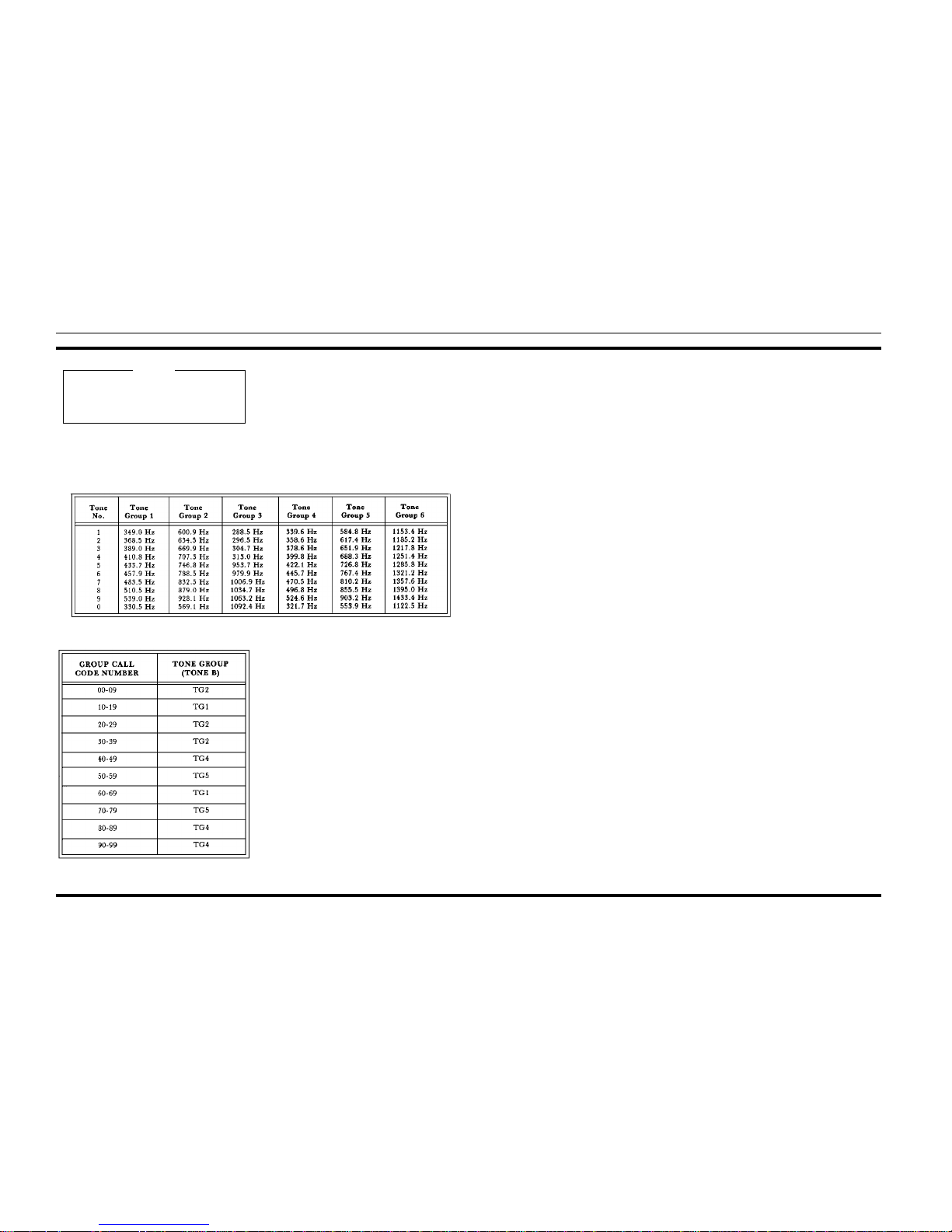
Example 1 - Group Call Code 07 (also code 27 and 37):
The digit "0" in Table 5 shows that Tone B is in Tone
Group 2 along with 20 to 29 and 30 to 39. Tone number 7 in
Tone Group 2 is 832.5 Hz (see Table 6).
Example 2 - Group Call 98 (also code 48 and 88 ):
The digit "9" in Table 5 shows that Tone B is in Tone
Group 4 along with 40 to 49 and 80 to 89. Tone number 8 in
Tone Group 4 is 496.8 Hz.
Group Call code numbers range from 00 to 99. However, there are several Group Calls with the same Tone
B frequency. This limits the total number of Group
Calls to 40.
NOTE
Table 6 - Motorola Group Call Tone Groups (TG)
Table 7 - Motorola Group Call Tone Groups (TG)
LBI-38652 LBI-38652
7
Page 9
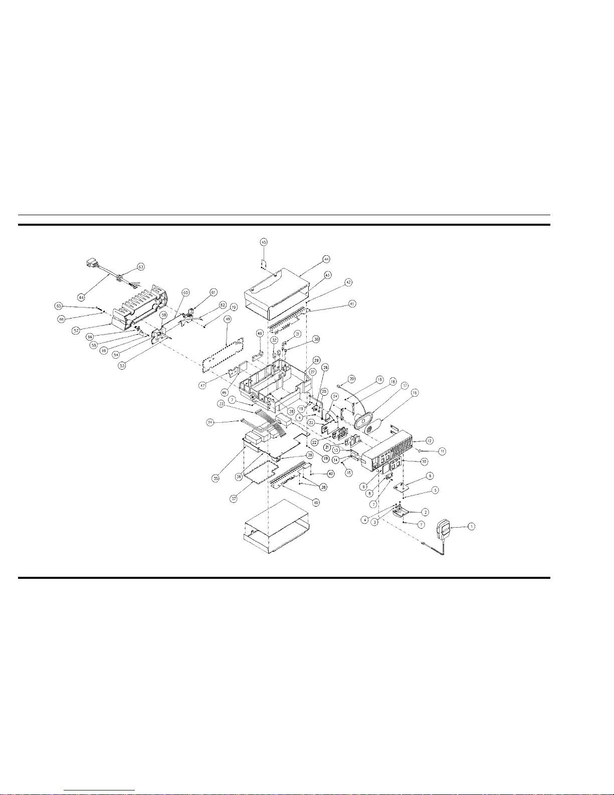
MECHANICAL PARTS BREAKDOWN
LBI-38652 LBI-38652
8
Page 10
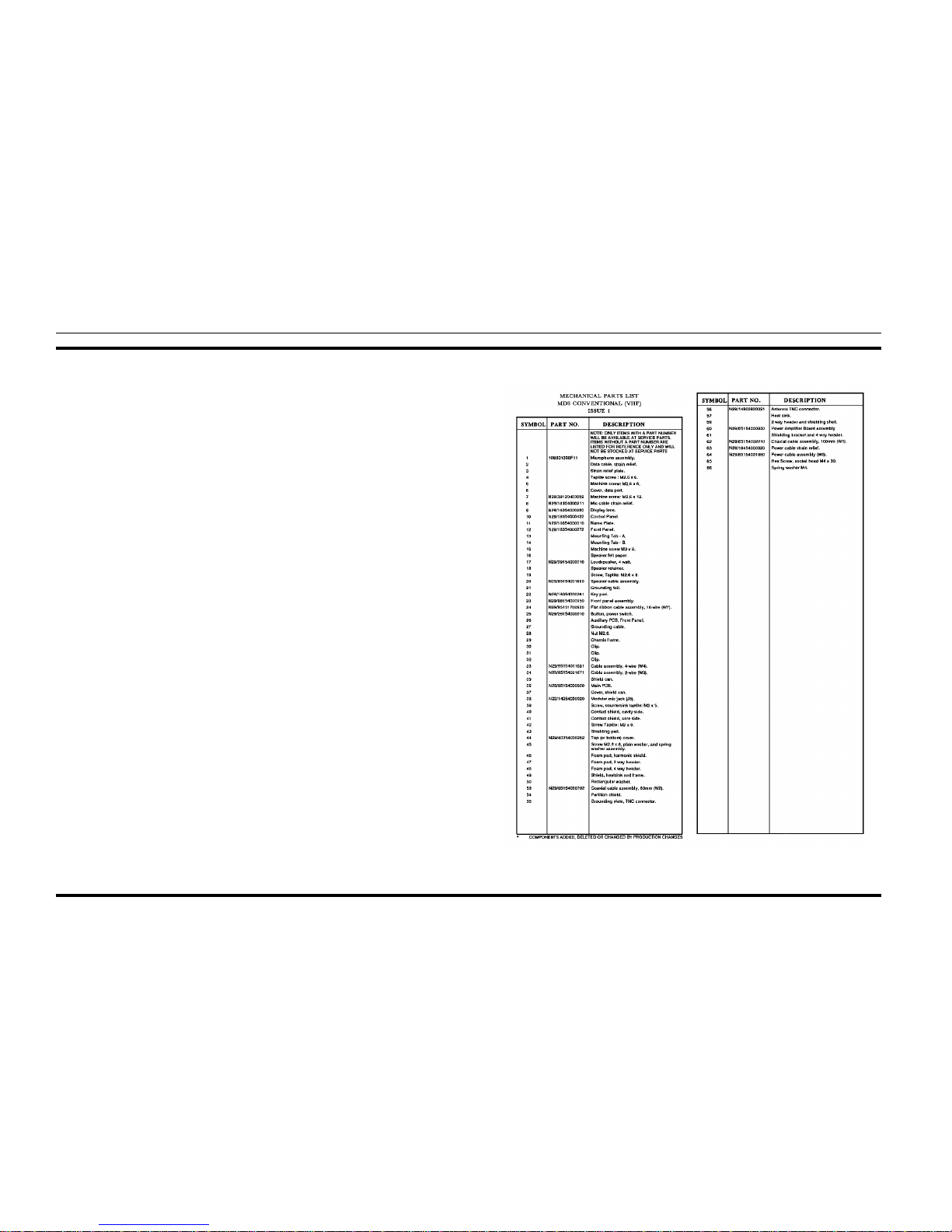
PARTS LIST
LBI-38652 LBI-38652
9
 Loading...