

Page 1
Mobile Communications
EDACS FMD
SELECT MODEL
Operator’s Manual
LBI-38102A
Page 2

Copyright© May 1988, General Electric Company
TABLE OF CONTENTS
Section/Paragraph Page
INTRODUCTION . . . . . . . . . . . . . . . . . . . . . . . . 3
CONTROLS AND DISPLAYS . . . . . . . . . . . . . . . . . 3
DISPLAYS . . . . . . . . . . . . . . . . . . . . . . . . . . 4
CONTROLS . . . . . . . . . . . . . . . . . . . . . . . . . . 5
EMERGENC Y FEATURE . . . . . . . . . . . . . . . . . . 5
OPERATION . . . . . . . . . . . . . . . . . . . . . . . . . . . 6
GROUP SELECTION . . . . . . . . . . . . . . . . . . . . 6
SYSTEM SEL EC TI O N . . . . . . . . . . . . . . . . . . . . 6
GETTING STARTED . . . . . . . . . . . . . . . . . . . . 6
SETTING BACKLIGHT LEVEL . . . . . . . . . . . . . . 7
SENDING AND RECEIVING TR UNKED ME SSAGE S . . 7
Receiving A Message . . . . . . . . . . . . . . . . . . . 7
Sending A Message . . . . . . . . . . . . . . . . . . . . 7
SENDING AND RECEIVING
CONVENTIONAL MESSAGES . . . . . . . . . . . . . . . 8
Receiving A Message . . . . . . . . . . . . . . . . . . . 8
Sending A Message . . . . . . . . . . . . . . . . . . . . 8
SPECIAL FEATURES . . . . . . . . . . . . . . . . . . . . . . 9
ALERT TONES . . . . . . . . . . . . . . . . . . . . . . . . 9
RECEIVING AN E MERGENCY CALL . . . . . . . . . . 10
SENDING AN EMERGENCY CAL L . . . . . . . . . . . . 10
CLEARING AN EMERGENCY CAL L . . . . . . . . . . . 10
SPECIAL CALL . . . . . . . . . . . . . . . . . . . . . . . 10
Receivi ng An Indivi dua l Call (Tru nke d Mode) . . . . . . 10
Sending A Special Call . . . . . . . . . . . . . . . . . . 11
Telephon e Interconnect . . . . . . . . . . . . . . . . . . 11
IN CASE OF DIFFICULTY . . . . . . . . . . . . . . . . . . . 12
OPERATING TIPS . . . . . . . . . . . . . . . . . . . . . . . . 12
2
A. Ericsson GE Mobile Comm unications Inc. (hereinafter "Seller") w arrants to the original
purchaser for use (hereinafter "Buyer") that Equipment manufactured by Seller shall be
free from defects in material, workmanship and title, and shal l conform to its published
specifications. With respect to any Equipment not manufactured by Seller (except for in-
tegral parts of Seller’s Equipment to which the warranties set forth above shall apply).
Seller gives no warranty, and only the warranty, if any, given by the manufacturer shall
apply. Batteries are excluded from this warranty but are warranted under a separate
Nickel-Cadmium Battery Warranty.
B. Seller’s obligati ons set forth in Paragraph C below shall apply only to failures to meet
the above warranties (except as to title) occurring withi n the following periods of time
from date of sale to the Bu yer and are conditioned on Buyer’s giving written notice to
Seller within thirty (30) days of such occurrence:
1. for fuses, incandescent lamps, vacuum tubes and non-rechargeabl e batteries, op-
2. for parts and accessories (except as noted in B.1) sold by Seller’s Service Parts
3. for all other Equipment of Seller’s manufacture, one (1) year.
C. If any Equipment fails to meet the foregoing warrantie s, Seller shall correct the failure at
its option (i) b y repairing any defective or damaged part or parts thereof, or (ii) by ma k-
ing a vailabl e at Selle r’s factory any necessary repaired or replacement parts. Any re-
paired or replacement part furnished hereunder shall be warranted for the remainder of
the warranty period of the Equipment in which it is installed. Where such failure cannot
be corrected by Seller’s reasonable efforts, the parties will negotiate an equitable adjust-
ment in price. Labor to perform warranty service will be provided at no change only for
the Equipment c overed under Paragraph B.3, and only during the first three (3) months
followi ng the date of sale to the Buyer. Thereafter, labor will be charged at prevailing
rates. To be eligible for no-charge labor, se rvice must be performed by an authorized
General Electric Service Station or other Servicer approved for these purposes either at
its place of business during normal business hours, for mobile o r personal equi pment,
or at the Buyer’s location, for fixed location equipment. Service on fixed location equip-
ment more than thirty (30) miles from the Service Station or other approved Servicer’s
place of business will include a charge for transportation. Equipment located off-shore is
not eligible for no-charge labor.
D. Seller’s obligations under Paragraph C shall not apply to any Equipment, or part thereof,
which (i) has been modified or otherwise altered other than pursuant to Seller’s written
instructions or written approval or, (ii) is normally consumed in operation or, (iii) has a
normal life inherently shorter than the warranty periods specified in Paragraph B, or (iv)
is not properly stored, installed, used, maintained or repaired, or, (v) has been subjected
to any other kind of misuse or detrimental exposure, or has been involved in an acci-
dent.
E. The preceding paragraphs set forth the exclusive remedies for claims (except as to title)
based upon defects in or nonconformity of the Equipment, whether the claim is in con-
tract, warranty, tort (including negligence), strict liability or otherwise, and however insti-
tuted. Upon the expiration of the warranty period, all such liability shall terminate. The
foregoing warranties are exclusive and i n lieu of al l other wa rranties, whether oral, writ-
ten, expressed, implied or statutory. NO IMPLIED OR STATUTORY WARRANTIES OF
MERCHANTABILITY OR FITNESS FOR PARTICULA R PURPOSE SHALL APPLY. IN
NO EVENT SHALL THE SELLER BE LIABLE F OR ANY INCIDENTAL, C ONSEQUEN-
TIAL, SPECIAL, INDIRECT OR EXEMPLARY DAMAGES.
Page 3
INTRODUCTION
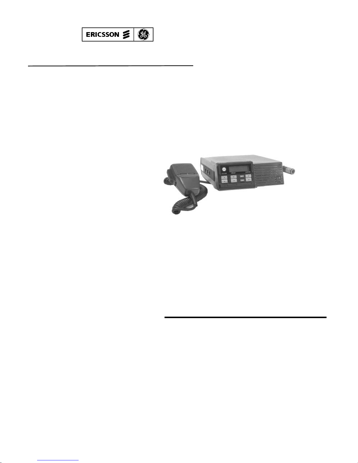
The EDACS FMD is a synthesized mobile radio designed for high
reliability and ease of operation. Its sma ll size makes the radio ideal for
front mounting. All operating controls and indicators are located on the
front pane l (Figu re 1). A few fea tur es of t he radio are list ed be low:
• Clear displa y, eve n in brigh t sunligh t
• Accommodates both voice and data transmission
• Button an d displ ay ba ck li ght ing for ni ght ti me opera t ion
• Adaptable for re m ot e moun ti ng
• External switc h sends inst an t eme rg en cy signa l
• Multiple Syste m s, Groups, and Cha nnels
• Special ca ll for radi o-t o-radio or tele phon e inte rc on ne ct
calls
CONTROLS AND DISPLAYS
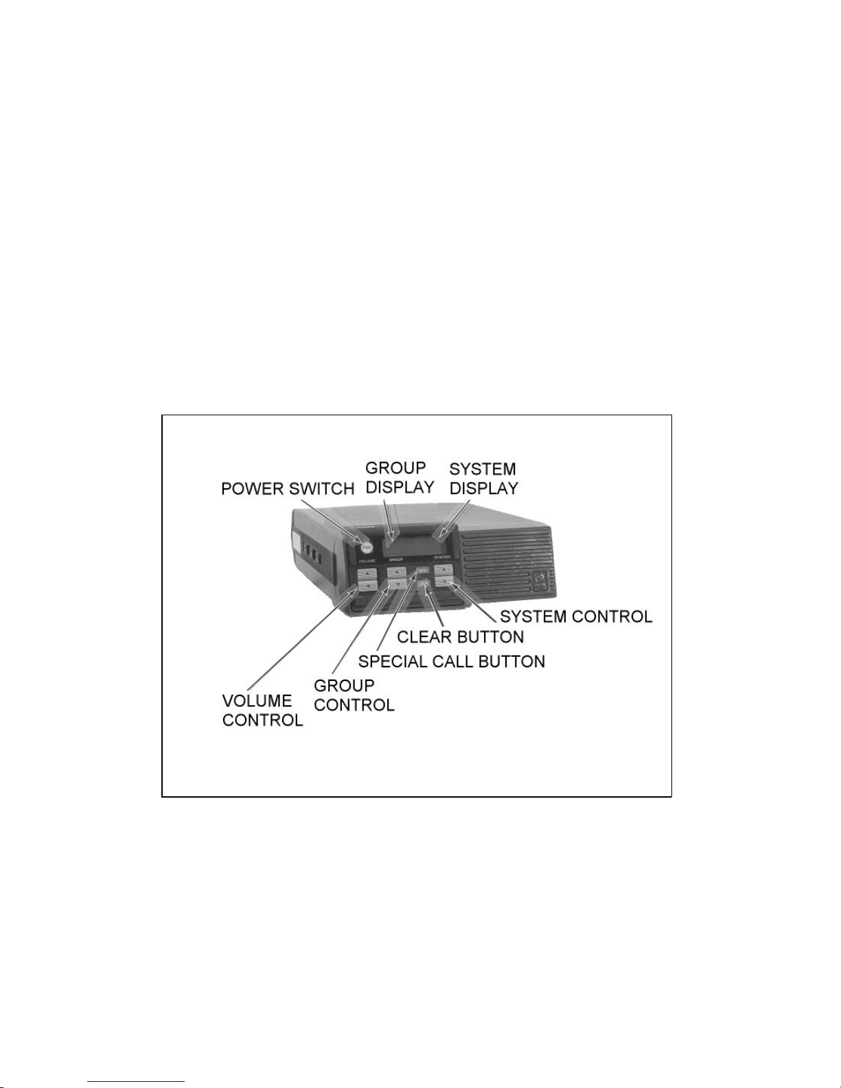
Controls and displays on the EDACS FMD Select model are described in this section.
FIGURE 1 - EDACS FMD SELECT CONTROL PANEL
3
Page 4
DISPLAYS
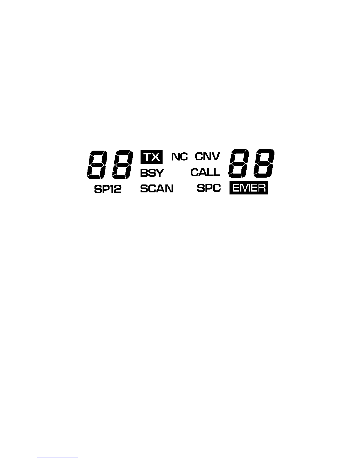
The display shows current operating information including Group,
System, or Channel. It also shows when the radio is in emergency operation and shows different status flags. An example of the display is
shown below with all the status flags displ ay ed . When you are using the
radio, only the active performance indicators and characters will show.
When the radio is tur ne d on, the displa y will show the syste m and grou p
selection.
TX Transmi t sta t us flag. Th is sta tus fl ag is on when the radi o is
tran smi tt ing.
BSY Channel busy status fla g. This status flag is on when the radio
recei ve s a cal l or when a conve nt ional channel is in use.
NC No control cha nn el sta tus fl ag . Thi s stat us fla g is on whe n the
control cha nn el is not avai la bl e (out of ran ge or not ope ra ti ng).
On supervisory un it s, the fla g flashe s when site equip ment is
in failsoft.
CNV Conventi onal system status flag. This status flag i s on when
operat ing on a conven ti ona l system .
EMER Emergen cy status flag. Displ aye d whe n the extern al eme r-
gency swit ch (opt ion al ) is activ at ed an d when an eme rge nc y
call is received.
CALL Flashes when progr amm e d calls ar e rece ived.
SPC Specia l call status flag. Displ a yed whe n an indi vi dua l call is
received or a special call is selected.
4
OPERATING TIP S
• Remem be r to wai t for the be e p be fore spe ak ing when transmit-
The following conditions tend to reduce the effective range of two-
way radio s and should be avoi de d whene ve r possible .
• Operati ng the rad io in low are a s of the te rra i n, or whil e under
• Obstructi ons such as mount ai ns or build ing s bet wee n the re-
Moving in another direction (towards the strongest signal), or mov-
ing to a hig he r ele vation, may a lso improve communic a ti on.
Page 5

SYSTEM Shows the selected syste m num ber.
GROUP Shows the selected group number.
The displ ay has a backl ig ht so you can rea d the di spla y at ni ght or in
dimly lit are as.
CONTROLS
PWR
(Power)
A red pushbutton is used to turn the radio on and off.
VOLUME These buttons set the receive volume level. Press the ▲
button to increase the volume or press the ▼ button to
lower the volume. Hold the button down until the desired
audio tone is heard (a tone will not be heard if the BSY
statu s flag is on). The radi o store s the select e d volume lev el
even when power is off.
GROUP The GROUP buttons change the group selection. Pressing
▲ or ▼ will change the group selection. The ▲ button se-
lects the next group, and ▼ button selects the previous
group.
SYSTEM These buttons change the system selection. Pressing ▲ or
▼ will change the system selection. The ▲ button selects
the next syste m, a nd ▼ but ton selec ts the prev iou s system .
SPC Pressing this button causes the radio to enter the special
Call mode. Special Call allows you to place calls to individual radios or telephone numbers. Use the GROUP ▲
and ▼ buttons to select Special Calls in Special Call mode.
CLR Used to clear an emergency (supervisory units only), clear
Spec ia l Ca l ls, and wh en sett ing the backlight leve l.
EMERGENCY FEATURE
Your radio is equipped with an emergency communications feature
that may be activated through an optional externally mounted switch.
When you activate the external emergency switch (optional), you will
be given the highest priority for voice communication. An emergency
5
Page 6

message with your ra dio ID will be sent to the dispatc he r an d your ra di o
display will show the EMER status flag. Everyone in your group will
see an eme rge ncy indi ca t ion on the i r ra dio s.
OPERATION
GROUP SELECTION
The GROUP buttons change your Group (or conventional channel)
selection. Press the ▲ button to view the next Group choice or ▼ to
view the previous Group choice. Release the button when the display
shows the Group you want. If the di spla ye d Group does not chan ge , you
have reached the limit and will have to press the opposite direction to
see other selections. These buttons will automatically ramp when held
down.
SYSTEM SELECTI ON
Select a trunked or conventional System by pressing the SYSTEM
buttons. Press the ▲ button to see the next System choice or press the
▼ button to see the previous System choice. Release the button when
the display shows the System you want. If the System message does not
change, you have reached the limit and will have to press the button in
the opposite direction to s ee other selections. These buttons will auto-
matically ramp when held down.
GETTING ST ART ED
1. Press the red PWR button to turn the radio on. The display will
becom e visibl e .
2. Adjust the volume using the VOLUME buttons.
Your radio is now set up for basic operation. The BSY status flag
will be on when a call is re c ei ve d.
The group may change when the system selection is changed. This
happens when the selected system does not contain the previously
selected group. Make sure the GROUP selection is correct after
selecti ng a SYSTEM.
NOTE
6
Sendi ng A Spe ci al Ca ll
You may make Special Calls with your radio through the Special
Call feature.
1. Press and release the SPC button. The SPC status flag will come
2. Pre s s the GROUP buttons to search (forwa rd or reverse dir ect ion )
3. Press the PT T button on the microphone and make your call.
4. Release the PTT button when you are done talking, and listen for
5. When the call is finished, press the CLR button or hang up the
Telephon e Interc onn ect
You may make telephone calls using the Special Call feature and an
optional DTMF microphone. Make a telephone interconnect call as fol-
lows:
1. Press the SPC button, the SPC status flag will come on. The sys-
2. Press the GROUP buttons until the special call number for tele-
3. Press the PTT button on the microphone and wait for a dial tone
4. Enter the telephone number followed by * (star) using the keypad
Page 7

SETTING BAC KLI GHT L EVEL
The leve l of bac kl igh ti ng for the LC D may be adjust ed as fol lows:
1. Press and hold the CLR button.
2. Press the GROUP ▲ or ▼ button until the desired level of back-
lighting (off, low, medium, or high) is obtained. The backlight
leve l is stored when the radio is turned off .
3. Release the CLR button.
SENDING AND RECEIVING TR UNKED ME SSAGE S
When operating in a trunked system (normal operation), use the procedures in this section. Operation in the conventional channel mode is
described under SENDING AND RECEIVING CONVENTIONAL
MESSAGES.
Receiving A Messa ge
1. Press the VOLUME button and listen for the desired level of
audio ton e.
2. Select the trunked system by operat ing the SYST EM butt ons.
3. Select the desired group by opera ting the GROUP butt ons.
The radio will now receive calls directed to the selected system and
group. If an individual call (call directed only to your radio) is received,
the SPC and BSY status fla gs wil l be displa ye d.
Sending A Messa ge
1. Select the desired system by operat ing the SYST EM butt ons.
Pressing the CLR button disables the squelch on conventional
channels. You may want to reduce the volume before setting the
backlight level to pre ve nt exc e s sive noise in the sp ea ke r.
NOTE
7
Page 8

2. Select the desired group by opera ting the GROUP butt ons.
3. When the BSY status flag is off, press the PTT button on the microphone. Wait until the TX and BSY status flags are displayed
and a tone is he ard.
4. Hold the microphone about six inches from your mouth and
speak normally.
5. Release the PTT button when the transmission is complete, and
listen for any reply. The TX and BSY sta tus fla gs will go off.
SENDING AND RECEIVING CONVE NTI ONAL ME SSAGE S
The procedures described here are for operating in a conventional
channel mode. Use these procedures if you have a conventional system,
or in the event of a failure of the trunked system.
Receiving A Messa ge
1. Press the VOLUME button and listen for the desired level of
audio ton e.
2. Select a conventional channel system by operating the SYSTEM
buttons.
3. Select the desired channel by op erating the GROUP buttons. The
radio will now rec eive messa ge s over the chan nel.
Sending A Messa ge
1. Select a conventional channel system by operating the SYSTEM
buttons.
2. Select the desired channel by operating the GROUP buttons.
3. Insure that there is no other transmission on the channel (BSY
status flag off).
4. Press the PTT button on the microphone and wait until the TX
status fla g is displ a ye d an d a tone is hear d.
8
5. Hold the microphone about six inches from your mouth and
6. Release the PTT button when the transmission is complete, and
SPECIAL FEATURES
ALERT TONES
Your radio produc es audio tones when th e buttons ar e presse d an d at
othe r time s duri ng normal ope ra ti on.
• Short tone when a button is pressed.
• Short tone when emerge nc y opera tion is used.
• Short tone after PTT is pressed and radio is ready to transm it.
• Call-queued tone. A high pitched beep signalling the call has
• System busy. Th ree low pitched beeps indi ca ting the system is
• Auto-ke y tone . A long tone if the PTT is not presse d whe n th e
• Carrie r Cont rol Tim er (CCT) T one . A warning signal which
Page 9

5. Hold the microphone about six inches from your mouth and
speak normally.
6. Release the PTT button when the transmission is complete, and
listen for any reply. The TX status flag will go off.
SPECIAL FEATURES
ALERT TONES
Your radio produc es audio tones when th e buttons ar e presse d an d at
othe r time s duri ng normal ope ra ti on.
• Short tone when a button is pressed.
• Short tone when emerge nc y opera tion is used.
• Short tone after PTT is pressed and radio is ready to transm it.
• Call-queued tone. A high pitched beep signalling the call has
been queue d and wi ll be place d as soon as a chann el is assigne d.
Wait until call is placed. The radio flashes the BSY status flag
and disables PTT when a call is queued.
• System busy. Th ree low pitched beeps indi ca ting the system is
busy . Try yo ur c al l lat e r.
• Auto-ke y tone . A long tone if the PTT is not presse d whe n th e
site equipment assign s a channel. You have up to two seconds to
press the PTT aft er the tone to keep the assig ned ch anne l.
• Carrie r Cont rol Tim er (CCT) T one . A warning signal which
sounds afte r the radi o has been cont inu ously transmitting for a
pre-prog ra mme d tim e. The signa l turns off when PTT is release d. A five-be e p sign al fol lowe d by a low tone is used on
trunked systems. On conventional systems, the low tone beep
sounds until PTT is released.
9
Page 10

RECEIVING AN EMER GENC Y CALL
When you receive an emergency call a short beep will sound, the
EMER status flag will flash, and the BSY status flag will come on. Follow your sta nd ar d em e rge nc y pr ocedure s.
SENDING AN EMERGE NCY CAL L
To send an Emerge ncy cal l procee d as follows:
1. Activate the external emergency switch (optional). The EMER
and TX stat us fla gs wil l com e on (unle ss programmed off).
2. Press the PTT button on the microphone, and speak into the mi-
crophone in a normal voice.
3. Release the PTT button when the transmission is completed, and
listen for any reply. The TX status flag will go out.
CLEARING AN EME RGE NCY CAL L
If your radio has been programmed as a supervisory unit, you may
clea r em ergen cy calls . When the emer gency is no l ong er i n eff ect , th e
emergency call may be cleared as follows:
1. Press and hold the CLR button while pressing the ext ernal emer-
gency swit ch (opt ion al ).
2. Wait for the EMER status flag t o go off.
3. Release bo th butt ons.
SPECIAL CALL
Receivi ng An Ind ividual Call (Trunke d Mode )
When yo u rec eive an i ndi vidu al ca ll (cal l di rect ed o nly t o y our r adio), the CALL and BSY status flags will be displayed. If you want to
respond to the call, you have up to five seconds to press the PTT button.
Your call wil l auto mat ic a lly be direc te d to the sta ti on ca ll ing you.
10
SETTING BAC KLI GHT L EVEL
The leve l of bac kl igh ti ng for the LC D may be adjust ed as fol lows:
1. Press and hold the CLR button.
2. Press the GROUP ▲ or ▼ button until the desired level of back-
3. Release the CLR button.
SENDING AND RECEIVING TR UNKED ME SSAGE S
When operating in a trunked system (normal operation), use the pro-
cedures in this section. Operation in the conventional channel mode is
described under SENDING AND RECEIVING CONVENTIONAL
MESSAGES.
Receiving A Messa ge
1. Press the VOLUME button and listen for the desired level of
2. Select the trunked system by operat ing the SYST EM butt ons.
3. Select the desired group by opera ting the GROUP butt ons.
The radio will now receive calls directed to the selected system and
group. If an individual call (call directed only to your radio) is received,
the SPC and BSY status fla gs wil l be displa ye d.
Sending A Messa ge
1. Select the desired system by operat ing the SYST EM butt ons.
Pressing the CLR button disables the squelch on conventional
channels. You may want to reduce the volume before setting the
backlight level to pre ve nt exc e s sive noise in the sp ea ke r.
Page 11

Sendi ng A Spe ci al Ca ll
You may make Special Calls with your radio through the Special
Call feature.
1. Press and release the SPC button. The SPC status flag will come
on and the system display will change to SP. The group display
will change to the previ ously selec te d spec ia l call numbe r.
2. Press the GROUP buttons to search (forward or reverse dir ec t ion )
through the displayed list of Special Call numbers. When the desired Special Call number appears on the display, release the
GROUP button.
3. Press the PT T button o n the microphone and make your c all.
4. Release the PTT button when you are done talking, and listen for
any reply.
5. When the call is finished, press the CLR button or hang up the
microphone. The display will change to the previously selected
group and system.
Telephon e Interc onn ect
You may make telephone calls using the Special Call feature and an
optional DTMF microphone. Make a telephone interconnect call as follows:
1. Press the SPC button, the SPC status flag will come on. The sys-
tem display will change to the letters SP. The group display will
change to one of the previ ously selec ted spe cia l call numbe rs.
2. Press the GROUP buttons until the special call number for tele-
phone inter co nne c t appe a rs in th e gr oup di spla y.
3. Press the PTT button on the microphone and wait for a dial tone
(or ringing if the numb er is pre-stor ed ).
4. Enter the telephone number followed by * (star) using the keypad
on the microphone. Allow enough time for the transmitter to key
11
Page 12

when dialing telephone numbers. If the number is pre-stored, skip
this Step. Re lease th e P TT button.
5. When the call is answered, press the PTT button and wait for the
tone before speaking.
6. Release the PTT button and listen for any reply.
7. When your call is finished, press the CLR button. The previously
selecte d grou p and syste m will app ear on the displ a y.
IN CASE OF DIFFICULTY
The following suggestions should be tried before returning your ra-
dio for servi ce .
PROBL EM SOLUTIO N
First part of message not
sent.
Channel not assigned before transmitting
(trunked system). Wait for beep tone before
beginning message.
Mes sage s not re ce ived . 1. Volume lev e l se t to o low . In c reas e se tti ng
of VOLUME control.
2. Out of range of repeater or station.
Messages not transmitted. 1. Radio not turned on.
2. PTT not fully pressed. Make sure TX
status flag is on before transmitting.
3. Out of range of repeater or station.
Transmitted messages are
garbled.
1. Too close or too far from microphone.
Try different distance from microphone,
and/ or diff erent sp eaking level.
2. Out of range of repeater or station.
You cannot talk and listen at the same time as with a regular
telep hone. When ev er you talk you wi ll not he ar the other pa rty.
NOTE
12
SYSTEM Shows the selected syste m num ber.
GROUP Shows the selected group number.
The displ ay has a backl ig ht so you can rea d the di spla y at ni ght or in
dimly lit are as.
CONTROLS
PWR
(Power)
VOLUME These buttons set the receive volume level. Press the ▲
GROUP The GROUP buttons change the group selection. Pressing
SYSTEM These buttons change the system selection. Pressing ▲ or
SPC Pressing this button causes the radio to enter the special
CLR Used to clear an emergency (supervisory units only), clear
EMERGENCY FEATURE
Your radio is equipped with an emergency communications feature
that may be activated through an optional externally mounted switch.
When you activate the external emergency switch (optional), you will
be given the highest priority for voice communication. An emergency
Page 13

OPERATING TIP S
• Remem be r to wai t for the be e p be fore spe ak ing when transmit-
ting.
The following conditions tend to reduce the effective range of two-
way radio s and should be avoi de d whene ve r possible .
• Operati ng the rad io in low are a s of the te rra i n, or whil e under
power lines or br idg es.
• Obstructi ons such as mount ai ns or build ing s bet wee n the re-
peater site and the individual receiving the message.
Moving in another direction (towards the strongest signal), or mov-
ing to a hig he r ele vation, may a lso improve communic a ti on.
13
Page 14

SAFETY INFORM ATION
The operator of any mobile radio should be aware of certain hazards
commo n to the opera ti on of ve hi cula r ra di o tran smi ssi ons.
A list of the po ssi ble haz ar ds are:
• Explosive Atmosphe res
Just as it is dangerous to fuel a vehicle with the motor running, be
sure to turn the radio off while fueling the vehicle. Do Not carry
containers of fuel in the trunk of the vehicle when the radio is
mounte d in the trun k.
• Interference To Vehicular Elec troni c Syste m s
Electronic fuel injection systems, electronic anti-skid breaking
systems, electronic cruise control systems, etc., are typical of the
types of electronic devices that may malfunction due to the lack
of protection from radio frequency energy present when transmitting. If the vehicle contains such equipment, consult the dealer for
the make of vehicle and enlist his aid in determining if such electroni c cir cu it s perform norma ll y whe n th e radio is transm i tt ing .
• Dynamite Blasting Caps
Dynamite blasting caps may be caused to explode by operating a
radio within 500 feet of the b lasting caps. Always obey the "Turn
Off Two Way Radio" signs posted where dynamite is being used.
When transpo rti ng bla stin g caps in your ve hic le :
a. Carry the blasting caps in a closed metal box with a soft lin-
ing.
b. Leave the radio OFF whenever the blasting caps are being
put into or removed from the vehicle.
• Radio Freque ncy Energy
To prevent burns or related physical injury from radio frequency
energy, do not operate the transmitter when anyone outside of the
vehi cl e is wi th in t wo fe et of th e antenna.
14
INTRODUCTION
The EDACS FMD is a synthesized mobile radio designed for high
reliability and ease of operation. Its sma ll size makes the radio ideal for
front mounting. All operating controls and indicators are located on the
front pane l (Figu re 1). A few fea tur es of t he radio are list ed be low:
CONTROLS AND DISPLAYS
Controls and displays on the EDACS FMD Select model are de-
scribed in this section.
Page 15

WARRANTY
A. Ericsson GE Mobile Comm unications Inc. (hereinafter "Seller") w arrants to the original
purchaser for use (hereinafter "Buyer") that Equipment manufactured by Seller shall be
free from defects in material, workmanship and title, and shal l conform to its published
specifications. With respect to any Equipment not manufactured by Seller (except for integral parts of Seller’s Equipment to which the warranties set forth above shall apply).
Seller gives no warranty, and only the warranty, if any, given by the manufacturer shall
apply. Batteries are excluded from this warranty but are warranted under a separate
Nickel-Cadmium Battery Warranty.
B. Seller’s obligati ons set forth in Paragraph C below shall apply only to failures to meet
the above warranties (except as to title) occurring withi n the following periods of time
from date of sale to the Bu yer and are conditioned on Buyer’s giving written notice to
Seller within thirty (30) days of such occurrence:
1. for fuses, incandescent lamps, vacuum tubes and non-rechargeabl e batteries, operable on arrival only.
2. for parts and accessories (except as noted in B.1) sold by Seller’s Service Parts
Operation, ninety (90) days.
3. for all other Equipment of Seller’s manufacture, one (1) year.
C. If any Equipment fails to meet the foregoing warrantie s, Seller shall correct the failure at
its option (i) b y repairing any defective or damaged part or parts thereof, or (ii) by ma king a vailabl e at Selle r’s factory any necessary repaired or replacement parts. Any repaired or replacement part furnished hereunder shall be warranted for the remainder of
the warranty period of the Equipment in which it is installed. Where such failure cannot
be corrected by Seller’s reasonable efforts, the parties will negotiate an equitable adjustment in price. Labor to perform warranty service will be provided at no change only for
the Equipment c overed under Paragraph B.3, and only during the first three (3) months
followi ng the date of sale to the Buyer. Thereafter, labor will be charged at prevailing
rates. To be eligible for no-charge labor, se rvice must be performed by an authorized
General Electric Service Station or other Servicer approved for these purposes either at
its place of business during normal business hours, for mobile o r personal equi pment,
or at the Buyer’s location, for fixed location equipment. Service on fixed location equipment more than thirty (30) miles from the Service Station or other approved Servicer’s
place of business will include a charge for transportation. Equipment located off-shore is
not eligible for no-charge labor.
D. Seller’s obligations under Paragraph C shall not apply to any Equipment, or part thereof,
which (i) has been modified or otherwise altered other than pursuant to Seller’s written
instructions or written approval or, (ii) is normally consumed in operation or, (iii) has a
normal life inherently shorter than the warranty periods specified in Paragraph B, or (iv)
is not properly stored, installed, used, maintained or repaired, or, (v) has been subjected
to any other kind of misuse or detrimental exposure, or has been involved in an accident.
E. The preceding paragraphs set forth the exclusive remedies for claims (except as to title)
based upon defects in or nonconformity of the Equipment, whether the claim is in contract, warranty, tort (including negligence), strict liability or otherwise, and however instituted. Upon the expiration of the warranty period, all such liability shall terminate. The
foregoing warranties are exclusive and i n lieu of al l other wa rranties, whether oral, written, expressed, implied or statutory. NO IMPLIED OR STATUTORY WARRANTIES OF
MERCHANTABILITY OR FITNESS FOR PARTICULA R PURPOSE SHALL APPLY. IN
NO EVENT SHALL THE SELLER BE LIABLE F OR ANY INCIDENTAL, C ONSEQUENTIAL, SPECIAL, INDIRECT OR EXEMPLARY DAMAGES.
This warranty applies only within the United States.
1-800-528-7711 (1-800-237-0138 in Virginia).
ECX-362R
15
Page 16

EMERGENCY NUMBERS
___________ ________________ ________________ ______________
Poli ce
___________ ________________ ________________ ______________
State Police
___________ ____ ________________ ____ ________________ ____ __
Fire
___________ ____ ________________ ____ ________________ ____ __
Poison Contro l
___________ ____ ____ ____ ____ ________________ ____ ____ ____ __
Ambulance
Life Saving and Rescue Squad
_________________________________________________________
Printed in U.S.A.
Mobile Communications
Operator’s Manual
LBI-38102A
 Loading...