


Mobile Communications
INTERNAL BATTERY
STANDBY CHARGER
OPTION BC01 (9669), 9670 AND 9771
(FOR MASTR
®
II STATIONS)
Printed in U.S.A.
Maintenance Manual
LBI-30869L

DESCRIPTION
The Battery Standby Charger (Option BC01 [9669]) consists of a voltage regulator and relay switching circuit mounted
on a printed board to provide a charging current for the storage
battery when the station power supply is operating normally.
The relay switching circuit switches to battery power and
switches the power supply bleeder resistor from the circuit in
the event of a power failure. Typical charge time is 48 hours
for a 55 AMP-HOUR automotive type lead-acid battery, that is
in good condition.
Option 9670/9771 is the same as Option BC01 (9669) with the
addition of an RF Relay and connecting cables. 9670 is used
in tube stations, 9771 is used in solid state station applications.
The operation is the same as Option BC01 (9669) in addition
the RF Relay automatically switches the driver RF output
directly to the antenna Relay, thereby bypassing the High
Power RF Power Amplifier. The charger board mounts on the
inside of the rear panel of the driver power supply and all
necessary leads for connection to the power supply and battery
are hanging from the board. The RF Relay mounts on the power
panel of the High Power Station.
ADJUSTMENT AND TEST
Adjustment
R4 (R16 for Group 2) is set at the factory and normally doesn’t
need adjustment but if the voltage at the black and red battery
leads (with the battery disconnected) exceeds 14.5 Volts DC,
adjust R4 or R16 for 14 Volts with the battery disconnected.
Test
To test the operation of the Relay switching circuit, turn off the
station power supply. The relay K1 should drop out and the
station should now be operating on the battery supply.
CIRCUIT ANALYSIS
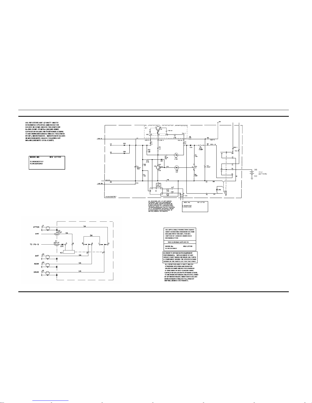
When the station power supply is operating normally, approximately 22 Volts AC appears at H3 and H4. This voltage provides the input voltage for the bridge rectifier CR1-CR4. The
voltage and current regulator consists of Q1 (the pass transistor) and Q2 (the driver transistor). R2 is the current se nsing
resistor to limit the short circuit current. A voltage divider
network made up of R3, R4 or R16 and R5, provides a variable
voltage
adjusted with R4 or R16 to set the bias on the base of Q2
which in turn controls the conduction of Q1 (the pass transistor). C1 and C806 provide filtering of the input voltage. The
output of the regulator is fused through F1 to provide over-load
protection. The regulated voltage also provides the voltage to
energize the K1 relay. When the station power supply is off for
any reason the regulator is off because no input voltage is fed
to it. With no voltage applied K1 de-energizes and the battery
is switched in as the power source and the power supply
bleeder resistor is switched out of the circuit. Refer to Figure
1 and Figure 2 for curves of RF Power output of the transmitter against time for intermittent and continuous duty
stations.
Copyright © 1979, Ericsson GE Mobile Communications Inc.
TABLE OF CONTENTS
Page
DESCRIPTION . . . . . . . . . . . . . . . . . . . . . . . . . . . . . . . . . . . . . . . . . . . . . . . . . . . 1
ADJUSTMENT & TEST . . . . . . . . . . . . . . . . . . . . . . . . . . . . . . . . . . . . . . . . . . . . . . 1
CIRCUIT ANALYSIS . . . . . . . . . . . . . . . . . . . . . . . . . . . . . . . . . . . . . . . . . . . . . . . . 1
FIGURE 1 AND FIGURE 2 . . . . . . . . . . . . . . . . . . . . . . . . . . . . . . . . . . . . . . . . . . . . . 1
OUTLINE DIAGRAMS
RF Relay Assembly . . . . . . . . . . . . . . . . . . . . . . . . . . . . . . . . . . . . . . . . . . . . . . . 2
Battery Standby Charger . . . . . . . . . . . . . . . . . . . . . . . . . . . . . . . . . . . . . . . . . . . . 2
SCHEMATIC DIAGRAMS
Battery Standby Charger (19A138358G2) . . . . . . . . . . . . . . . . . . . . . . . . . . . . . . . . . . . 3
Relay Assembly (19C321398G1, 2) . . . . . . . . . . . . . . . . . . . . . . . . . . . . . . . . . . . . . . 3
Battery Standby Charger (19A138358G1) Used in earlier Production Models . . . . . . . . . . . . . . . 8
PARTS LIST
Battery Standby Charger (19A138358G2) . . . . . . . . . . . . . . . . . . . . . . . . . . . . . . . . . . . 4
Coaxial Relay & Cable (19C321398G1, 2) . . . . . . . . . . . . . . . . . . . . . . . . . . . . . . . . . . 9
Battery Standby Charger (19A138358G1) Used in earlier Production Models . . . . . . . . . . . . . . . 9
INSTALLATION INSTRUCTIONS
Battery Standby Charger (Option 9670) . . . . . . . . . . . . . . . . . . . . . . . . . . . . . . . . . . . . 5
Battery Standby Charger (Option 9771) . . . . . . . . . . . . . . . . . . . . . . . . . . . . . . . . . . . . 6
RF Relay Assembly (Option 9670 and 9771) . . . . . . . . . . . . . . . . . . . . . . . . . . . . . . . . . 7
Battery Standby Charger (Option BC01 [9669]) . . . . . . . . . . . . . . . . . . . . . . . . . . . . . . . 7
Figure 1 - RF Power Output Versus Time Intermittent Only
Figure 2 - RF Power Output Versus Time Continuous Duty
LBI-30869 LBI-30869
1

CHARGER 19A138358G2
RF RELAY ASSEMBLY 19C321398G1, 2
OUTLINE DIAGRAM
CHARGER
VIEW IN DIRECTION
OF ARROW A-A
PARTIAL
RF RELAY ASSEMBLY
(19C321634, Rev 0)
(19D433257, Rev 0)
(19A143749, Sh. 1, Rev. 1)
COMPONENT SIDE
(19D433257, Rev 0)
(19A143749, Sh. 2, Rev. 1)
SOLDER SIDE
LBI-30869 LBI-30869
2
BATTERY STANDBY CHARGER 19A138358G2
RELAY ASSEMBLY 19C321398G1, 2
SCHEMATIC DIAGRAMLBI-30869 LBI-30869
3

PARTS LISTLBI-30869 LBI-30869
4

INSTALLATION INS TRUCTIONS
BATTERY STANDBY CHARGER
19A138358G2
OPTION BC01
(19D430298, Sh. 2, Rev. 1)
LBI-30869 LBI-30869
5

RF RELAY ASSEMBLY
19C321398G, G2
OPTIONS 9670 & 9771
(19B232304, Rev. 3)
INSTALLATION INS TRUCTIONSLBI-30869 LBI-30869
6

INSTALLATION INS TRUCTIONS
BATTERY STANDBY CHARGER
HIGH POWER TUBE STATION
RF COAXIAL RELAY
OPTION 9670
(19B226736, Rev. 4)
BATTERY STANDBY CHARGER
HIGH POWER SOLID STATE RF COAXIAL RELAY
OPTION 9771
LBI-30869 LBI-30869
7

BATTERY STANDBY CHARGER
19A138558G1
(19D430280 Rev. 2)
SCHEMATIC DIAGRAM
****************
LBI-30869 LBI-30869
8

PARTS LISTLBI-30869 LBI-30869
9
 Loading...