

Page 1

LBI-33031B
Maintenance Manual
Rockwell Modem
Model R96FT (19A705178)
U.S. Robotics Courier Modem
Model 2400 (19A149786P1)
Model V.32 (19A149786P2)
ericssonz
Page 2
REV NO. TITLE
ROCKWELL MODEM TEST
SPECIFICATION/PURCHASE PART DRAWING
CONT ON SHEET SH NO. FIRST MADE FOR
1.0 SCOPE
2.0 DESCRIPTION
2.1 GETC SHELF
2.2 ROCKWELL MODEM BOARD
2.3 TEST SOFTWARE
3.0 SPECIFICATIONS
3.1 POWER SUPPLY
3.2 DATA TRANSMISSION
3.3 APPLICABLE DRAWINGS
GENERAL
ELECTRIC
m
m
TABLE OF CONTENTS
19A705178
CONT ON SHEET
F. C. F. O.
3
SH NO.
2
REVISIONS
4.0 TEST EQUIPMENT
5.0 TEST PROCEDURES
5.1 TEST PREPARATION
5.2 ROCKWELL MODEM TEST
6.0 PART DRAWING
6.1 VENDOR SPECIFICATION
6.2 MODEM TECHNICAL SPECIFICATIONS
L30
MADE BY
K P Dotson 11-19-86
ISSUED
Nov. 19, 1986
APPROVALS
DCB
11-18-86
M. R. P. D.
LYNCHBURG
DIV OR DEPT.
LOCATION
19A705178
CONT ON SHEET
PRINTS TO
SH NO.
3
2
Page 3

REV NO. TITLE
ROCKWELL MODEM TEST
SPECIFICATION/PURCHASE PART DRAWING
CONT ON SHEET SH NO. FIRST MADE FOR
1.0 SCOPE
GENERAL
ELECTRIC
m
m
19A705178
CONT ON SHEET
F. C. F. O.
4
SH NO.
3
REVISIONS
This document describes how to test the Rockwell Modem (R96FT) to insure operation of the 9600 bps serial data
transmission used in the Public Service Trunked System and Voice Guard
®
System.
Mechanical and Electrical specifications are also included mounting holes and overall dimensions are on Sh. 9 of
this drawing.
MADE BY
K P Dotson 11-19-86
ISSUED
Nov. 19, 1986
APPROVALS
DCB
11-18-86
M. R. P. D.
LYNCHBURG
DIV OR DEPT.
LOCATION
19A705178
CONT ON SHEET
L30
PRINTS TO
SH NO.
4
3
Page 4
REV NO. TITLE
ROCKWELL MODEM TEST
SPECIFICATION/PURCHASE PART DRAWING
CONT ON SHEET SH NO. FIRST MADE FOR
2.0 DESCRIPTION
The Rockwell Modem (R96FT) is a purchased part from the Rockwell Corporation used in the GETC™ shelf. The
Rockwell Modem is used to transmit and receive 9600 bps serial data to and from four-wire dedicated unconditioned
telephone 1ines under control of the GETC shelf.
2.1 GETC SHELF
The GETC shelf (19D901868) is used to test the Rockwell Modem as part of the shelf assembly.
2.2 PHONE MODEM BOARD (ROCKWELL R96FT)
The Rockwell R96FT is a board level synchronous serial 9600 bit per second modem. The GETC logic
board contains phone 1ine interface circuits (T1, T2 etc.) that couple the phone modem to the phone line.
2.3 TEST SOFTWARE
The GETC shelf is used as a test fixture for the test of the Rockwell Modem.
GENERAL
ELECTRIC
m
m
19A705178
CONT ON SHEET
F. C. F. O.
5
SH NO.
4
REVISIONS
The GETC exercises the testing of the Rockwell Modem via the built in test software known as SIMON on
the GETC.
MADE BY
K P Dotson 11-19-86
ISSUED
Nov. 19, 1986
APPROVALS
DCB
11-18-86
M. R. P. D.
LYNCHBURG
DIV OR DEPT.
LOCATION
19A705178
CONT ON SHEET
L30
PRINTS TO
SH NO.
5
4
Page 5
REV NO. TITLE
ROCKWELL MODEM TEST
SPECIFICATION/PURCHASE PART DRAWING
CONT ON SHEET SH NO. FIRST MADE FOR
3.0 SPECIFICATIONS
3.1 POWER SUPPLIES
13.8 volts nominal GETC power supply.
Refer to the GETC test specification (19A705179).
Modem Input Power +5 Volts +/-5% < 700 Ma
+12 Volts +/-5% < 20 Ma
-12 Volts +1-5% < 80 Ma
3.2 DATA RATE
Data Rate 9600 +1 -1 Bit/Second
Input Level Range - 43 dBm to 0 dBm
Output Level 0 dBm
Train Time 30 msec
GENERAL
ELECTRIC
m
m
19A705178
CONT ON SHEET
F. C. F. O.
6
SH NO.
5
REVISIONS
3.3 APPLICABLE DRAWINGS
DRAWING NO. DRAWING NAME
19D901868 GETC SHELF
19D901855 GETC LOGIC BOARD ASSEMBLY
19D901852 GETC LOGIC BOARD SCHEMATIC DIAGRAM
MADE BY
K P Dotson 11-19-86
ISSUED
Nov. 19, 1986
APPROVALS
DCB
11-18-86
M. R. P. D.
LYNCHBURG
DIV OR DEPT.
LOCATION
19A705178
CONT ON SHEET
L30
PRINTS TO
SH NO.
6
5
Page 6
REV NO. TITLE
ROCKWELL MODEM TEST
SPECIFICATION/PURCHASE PART DRAWING
CONT ON SHEET SH NO. FIRST MADE FOR
4.0 RECOMMENDED TEST EQUIPMENT
Refer to the GETC test specification (19A705179).
The test equipment necessary to set up the GETC for the Rockwell Modem
test is listed blow. This setup is performed once on the specified GETC.
QTY EQUIPMENT TYPE
1 6286A DC SUPPLY WITH CURRENT LIMIT (OR EQUIVALENT.)
1 OSCILLOSCOPE MEDIUM BANDWIDTH NON-STORAGE
1 FREQUENCY METER CAPABLE OF MEASURING l2 MHz
1 STANDARD TERMINAL
1 TRIPLETT AC VOLT OHMMETER MODEL 630-PL TYPE 5 or DVM
1 19D901868 GETC shelf
1 PROM with SIMON software (standard Application software)
The equipment necessary to test the Rockwell Modem is a GETC shelf
(19D901868).
GENERAL
ELECTRIC
m
m
19A705178
CONT ON SHEET
F. C. F. O.
7
SH NO.
6
REVISIONS
The GETC is used as a test fixture.
L30
MADE BY
K P Dotson 11-19-86
ISSUED
Nov. 19, 1986
APPROVALS
DCB
11-18-86
M. R. P. D.
LYNCHBURG
DIV OR DEPT.
LOCATION
19A705178
CONT ON SHEET
PRINTS TO
SH NO.
7
6
Page 7
REV NO. TITLE
ROCKWELL MODEM TEST
SPECIFICATION/PURCHASE PART DRAWING
CONT ON SHEET SH NO. FIRST MADE FOR
5.0 TEST PROCEDURES
5.1 PREPARATION FOR TEST
Refer to the GETC test specification for certain alignment procedures prior to testing of the Rockwell
Modem. Set up terminal with 19.2 KBaud rate, odd parity, full duplex, and all upper case letters. Connect
the terminal to the master communication link as follows:
SIGNAL GETC LOGIC TERMINAL
BOARD (D-TYPE CONNECTOR)
TXD J8-1 PIN 3
RXD J8-2 PIN 2
GND J8-3 PIN 7
SIMON is used to test the Rockwell Modem.
GENERAL
ELECTRIC
m
m
19A705178
CONT ON SHEET
F. C. F. O.
8
SH NO.
7
REVISIONS
MADE BY
K P Dotson 11-19-86
ISSUED
Nov. 19, 1986
APPROVALS
DCB
11-18-86
M. R. P. D.
LYNCHBURG
DIV OR DEPT.
LOCATION
19A705178
CONT ON SHEET
L30
PRINTS TO
SH NO.
8
7
Page 8
REV NO. TITLE
ROCKWELL MODEM TEST
SPECIFICATION/PURCHASE PART DRAWING
CONT ON SHEET SH NO. FIRST MADE FOR
5.2 ROCKWELL MODEM TEST
The GETC shelf setup procedures to configure it as the test fixture for the Rockwell Modem follows. These
procedures need to be implemented only once on the specified GETC shelf to be used as the Rockwell
Modem test fixture.
1) Plug the Rockwell Modem into J3 on the GETC test fixture.
2) Install P11 between J11-1 and J11-2 on the GETC logic board.
3) Connect a jumper between J6-7 and J6-9 on the GETC.
4) Connect a jumper between J6-6 and J6-8 on the GETC.
5) Install a 680 ohm resistor (1/4 watt) between J6-8 and J6-9.
6) Adjust R1 to about half range on the GETC.
GENERAL
ELECTRIC
m
m
19A705178
CONT ON SHEET
F. C. F. O.
9
SH NO.
8
REVISIONS
7) Adjust R2 to about half range on the GETC.
The procedures to test the Rockwell Modem follows:
l) Plug the Rockwell Modem into the test fixture.
2) Apply power (13.8 volts) to the GETC shelf and the SIMON welcome message is displayed on the
terminal. The GETC is DTP switch configured for SIMON operation prior to power up. See
19A701179 for dip switch set-up.
3) Type "TIM 19" on the terminal to set the time delay from RTS to beginning of data to 250
milliseconds.
4) Execute the SIMON command "MDS 1" to select the phone modem for subsequent BER
command.
5) Execute the SIMON command "BER DE-00=10". This command transmits data and
simultaneously checks to see that data is being received. The terminal should respond with the
following: Error Count = 0000 Receive Checksum = 00188123
If the terminal does not respond with the above data, the Rockwell Modem has failed the test and
needs to be returned to the vendor.
The test continually runs, outputting data to the terminal in 10 second intervals.
6) After four consecutive test periods (10 seconds per test pe riod) with data o utputted to the terminal,
the test can be terminated by pressing a CTRL Z or the ESC key on the terminal.
L30
MADE BY
K P Dotson 11-19-86
ISSUED
Nov. 19, 1986
APPROVALS
DCB
11-18-86
M. R. P. D.
LYNCHBURG
DIV OR DEPT.
LOCATION
19A705178
CONT ON SHEET
PRINTS TO
SH NO.
9
8
Page 9
REV NO. TITLE
ROCKWELL MODEM TEST
SPECIFICATION/PURCHASE PART DRAWING
CONT ON SHEET SH NO. FIRST MADE FOR
6.0 PART DRAWING
GENERAL
ELECTRIC
m
m
19A705178
CONT ON SHEET
F. C. F. O.
10
SH NO.
9
REVISIONS
INTRODUCTION
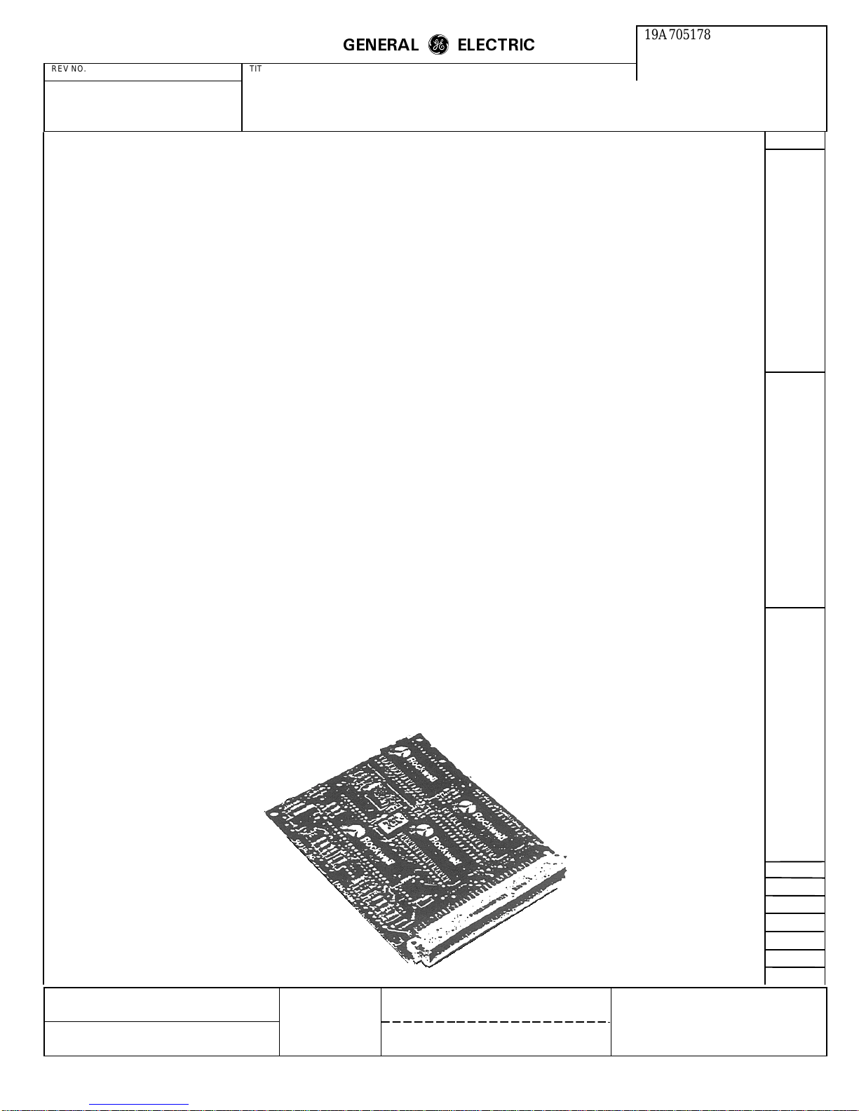
The Rockwell R96FT is a synchronous serial 9600 bps
modem designed for multipoint and networking
applications. The R96FT allows full-duplex operation o ver
4-wire dedicated unconditioned lines. or half-duplex
operation over the general switched telephone network.
Proprietary fast train configurations provide training times
of 23 ms for V.29FT/9600/7200/4800, 22 ms for
V.27FT/4800. and 30 ms for V.27FT/2400. A 2400/4800
bps Gearshift configuration provides a training time of 10
ms. For applications requiring operation with international
standards, fallback configurations compatible with CCITT
recommendations V.29 and V.27 bis/ter are provided. A
300 bps FSK configuration, compatible with CCITT V.21
Channel 2, is also provided.
The small size and low power consumption of the R96FT
offer the user flexibility in formulating a 9600 bps modem
design customized for specific packaging and functional
requirements.
This data sheet corresponds to assembly number
TR96D400-061 and subsequent revisions.
FEATURES
• Proprietary Fast Train
• 2400/4800 bps Gearshift
• User Compatibility
– CCITT V.29, V.27 bis/ter and V.21 Channel 2
• Train on Data
• Full-Duplex (4-Wire)
• Half-Duplex (2-Wire)
• Programmable Tone Generation
• Dynamic Range -43 dBm to 0 dBm
• Diagnostic Capability
• Equalization:
– Automatic Adaptive
– Compromise Cable (Selectable)
– Compromise Link (Selectable)
• DTE Interface:
– Microprocessor Bus
– CCITT V.24 (RS-232-C Compatible)
• Loopbacks
– Local Analog (V.54 Loop 3)
– Remote Analog (Locally Activated)
– Remote Digital (Locally ActivatedV.54 Loop 2)
• Small Size
– 100 mm x 120 mm (4.0 in. x 4.8 in.)
• Low Power Consumption
– 3 watts, typical
• Programmable Transmit Output Level
• TTL and CMOS Compatible
MADE BY
K P Dotson 11-19-86
ISSUED
Nov. 19, 1986
APPROVALS
DCB
11-18-86
M. R. P. D.
LYNCHBURG
DIV OR DEPT.
LOCATION
19A705178
CONT ON SHEET
10
L30
PRINTS TO
SH NO.
9
Page 10

REV NO. TITLE
ROCKWELL MODEM TEST
SPECIFICATION/PURCHASE PART DRAWING
CONT ON SHEET SH NO. FIRST MADE FOR
GENERAL SPECIFICATIONS
Voltage Tolerance Current (Max.)
+5 Vdc
+12 Vdc
-12 Vdc
Note: All voltages must have ripple ≤0.1 volts peak-to-peak.
Parameter Specification
Temperature
Operating
Storage
Relative Humidity Up to 90% noncondensing, or a wet bulb temperature up to
GENERAL
ELECTRIC
m
m
CONT ON SHEET
F. C. F. O.
POWER
19A705178
±
±
±
5%
5%
5%
<700 mA
<30 mA
<80 mA
ENVIRONMENTAL
0°C to + 60°C (32 to 140°F)
-40°C to +80°C (-40 to 176°F) Stored in heat sealed antistatic
bag and shipping container
35°C, whichever is less.
11
SH NO.
10
REVISIONS
MECHANICAL
Parameter Specification
Board Structure Single PC board with single right angle header with 64 pins.
Burndy P196B32R00A00Z1 or equivalent mating connector.
Dimensions Width - 3.94 in. (100 mm)
Length - 4.72 in. (120 mm)
Height - 0.4 in. (10.2 mm)
Weight Less than 3.6 oz (100g)
L30
MADE BY
R Sager
ISSUED
Nov. 19, 1986
APPROVALS
DCB
11-18-86
M. R. P. D.
LYNCHBURG
DIV OR DEPT.
LOCATION
19A705178
CONT ON SHEET
11
PRINTS TO
SH NO.
10
Page 11
REV NO. TITLE
ROCKWELL MODEM TEST
SPECIFICATION/PURCHASE PART DRAWING
CONT ON SHEET SH NO. FIRST MADE FOR
TECHNICAL SPECIFICATIONS
GENERAL
ELECTRIC
m
m
CONT ON SHEET
12
F. C. F. O.
At 1600 baud, the 4800 bps data stream is encoded into
tribits per CCITT V.27 bis/ter.
19A705178
SH NO.
11
REVISIONS
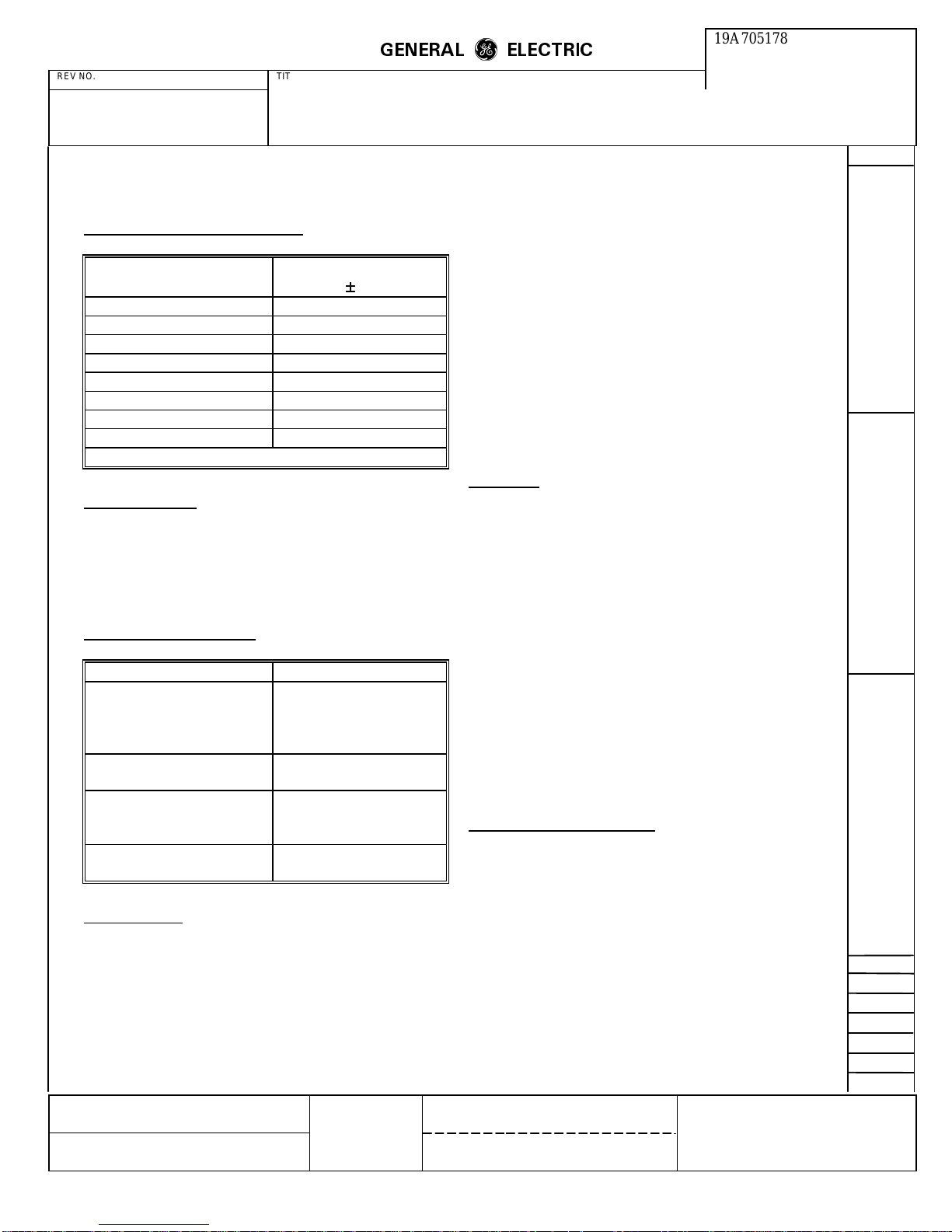
Transmitter Carrier Frequencies
Frequency
Function
(Hz ±
0.01%)
V27 bis/ter Carrier 1800
V27FT Carrier 1800
2400/4800 bps Gearshift 1800
V29 Carrier 1700
V29FT Carrier 1700/1800*
V21 Channel 2:
Mark 1650
Space 1650
*Selectable carrier frequency
Tone Generation
Under control of the host processor. the R96FT can
generate voice band tones up to 4800 Hz with a resolution
of 0.15 Hz and an accuracy of 0.01%. Tones over 3000 Hz
are attenuated.
Signaling And Data Rates
Parameter Specification
Signaling Rate:
Data Rate:
2400 baud
9600 bps
7200 bps
4800 bps
Signaling Rate:
Data Rate:
Signaling Rate:
Data Rate:
Gearshift Data Rate:
Signaling Rate:
Data Rate:
1600 baud
4800 bps
1200 baud
2400 bps
2400/4800 bps
300 baud
300 bps
At 1200 baud, the 2400 bps data stream encoded into dibits
per CCITT V.27 bis/ter.
For the Gearshift configuration, the signaling rate is 1200
baud. The 2400 bps data stream is encoded into dibits
forming a 4 point structure, and the 4800 bps data stream is
encoded into quadbits forming a l6-point structure. The
first 32 bauds of data are transmitted at 2400 bps and the
remaining message is transmitted at 4800 bps.
At 300 baud, the 300 bps data stream is encoded per
CCITT V.21 Channel 2 into a mark frequency of I650 Hz
and a space frequency of 1850 Hz
Equalizers
The R96FT provides equalization functions that improve
performance when operating over low quality lines.
Cable Equalizers
- Selectable compromise cable
equalizers in the receiver and transmitter are provided to
optimize performance over different lengths of non-loaded
cable of 0.4 mm diameter.
Link Equalizers
- Selectable compromise link cable
equalizers in the receiver optimize performance over
channels exhibiting severe amplitude and delay distortion.
Two standards are provided: U.S. survey long and Japanese
3-link.
Automatic Adaptive Equalizer
- An automatic adaptive T
equalizer is provided in the receiver circuit
Transmitted Data Spectrum
If the cable equalizer is no enabled the transmitter spectrum
is shaped by the following raised cosine filter functions:
Data Encoding
At 2400 baud. the data stream is encoded per CCITT V.29.
At 9600 bps, the data stream is divided in groups of fourbits (quadbits) forming a 16-point structure. At 7200 bps,
the data stream is divided into three bits (tribits) forming an
8-point structure. At 4800 bps. the data stream is divided
into two bits (dibits) forming a 4-point structure.
MADE BY
R Sager
ISSUED
Nov. 19, 1986
APPROVALS
DCB
11-18-86
1. 1200 Baud. Square root of 90 percent
2. 1600 Baud. Square root of 50 percent
3. 2400 Baud. Square root of 20 percent
The out-of-band transmitter power limitations meet those
specified by Part 68 of the FCC's rules, and typically
exceed the requirements of foreign telephone regulatory
bodies.
M. R. P. D.
LYNCHBURG
DIV OR DEPT.
LOCATION
19A705178
CONT ON SHEET
12
L30
PRINTS TO
SH NO.
11
Page 12
REV NO. TITLE
ROCKWELL MODEM TEST
SPECIFICATION/PURCHASE PART DRAWING
CONT ON SHEET SH NO. FIRST MADE FOR
Scrambler/Descrambler
GENERAL
ELECTRIC
m
m
Transmit Timing
19A705178
CONT ON SHEET
F. C. F. O.
13
SH NO.
12
REVISIONS
The R96FT incorporates a self-synchronizing scrambler/
descrambler. This facility is in accordance with either V.27
bis/ter or V.29 depending on the selected configuration.
The scrambler/descrambler facilities for Gearshift can be
selected to be in accordance with either V.27 bis/ter or
V.29. The scrambler/descrambler selection is made by
writing the appropriate configuration codes into the
transmitter and receiver.
Received Signal Frequency Tolerance
The receiver circuit of the R96FT can adapt to received
frequency error of up to ±10 Hz with less than 0.2 dB
degradation in BER performance.
During fast train polling, frequency offset must be less than
±2 Hz for successful training.
Receive Level
The receiver circuit of the modem satisfies all specific
performance requirements for received line signal levels
from 0 dBm to -43 dBm. The received line signal level is
measured at the receiver analog input (RXA).
Receive Timing
The R96FT provides a data derived Receive Data Clock
(RDCLK) output in the form of a squarewave. The low-tohigh transitions of this output coincide with the centers of
received data bits. For the Gearshift configuration, the first
32 bauds of data are at 2400 bps followed by 4800 bps data
for the remaining message. The timing recovery circuit is
capable of racking a ±0.0l% frequency error in the transmit
timing source. RDCLK duty cycle is 50.% ±1%.
The R96FT provides a Transmit Data Clock (TDCLK)
output with the following characteristics:
1. Frequency. Selected data rate of 9600,7200.4800,2400
or 300 Hz (±0.01%). For the Gearshift configuration,
TDCLK is a 2400 Hz clock for the first 32 bauds of
data and a 4800 Hz clock for the remaining message.
2. Duty Cycle. 50% ±1%
Input data presented on TXD is sampled by the R96FT at
the low-to-high transition of TDCLK. Data on TXD must
be stable for at least one microsecond prior to the rising
edge of TDCLK and remain stable for at least one
microsecond after the rising edge of TDCLK.
External Transmit Clock
The transmitter Data clock (TDCLK) can be phase locked
to a signal on input XTCLK. This input signal must equal
the desired data rate ±0.01 with a duty cycle of 50% ±20%.
Train On Data
When train on data is enabled (by setting a bit in the
interface memory), the modem monitors the EOM signal. If
EOM indicates a loss of equalization (i.e., BER
approximately 10
-3
for 0.5 seconds) the modem attempts to
retrain on the data stream. The time for retrain is typically
3 to 15 seconds.
Turn-On Sequence
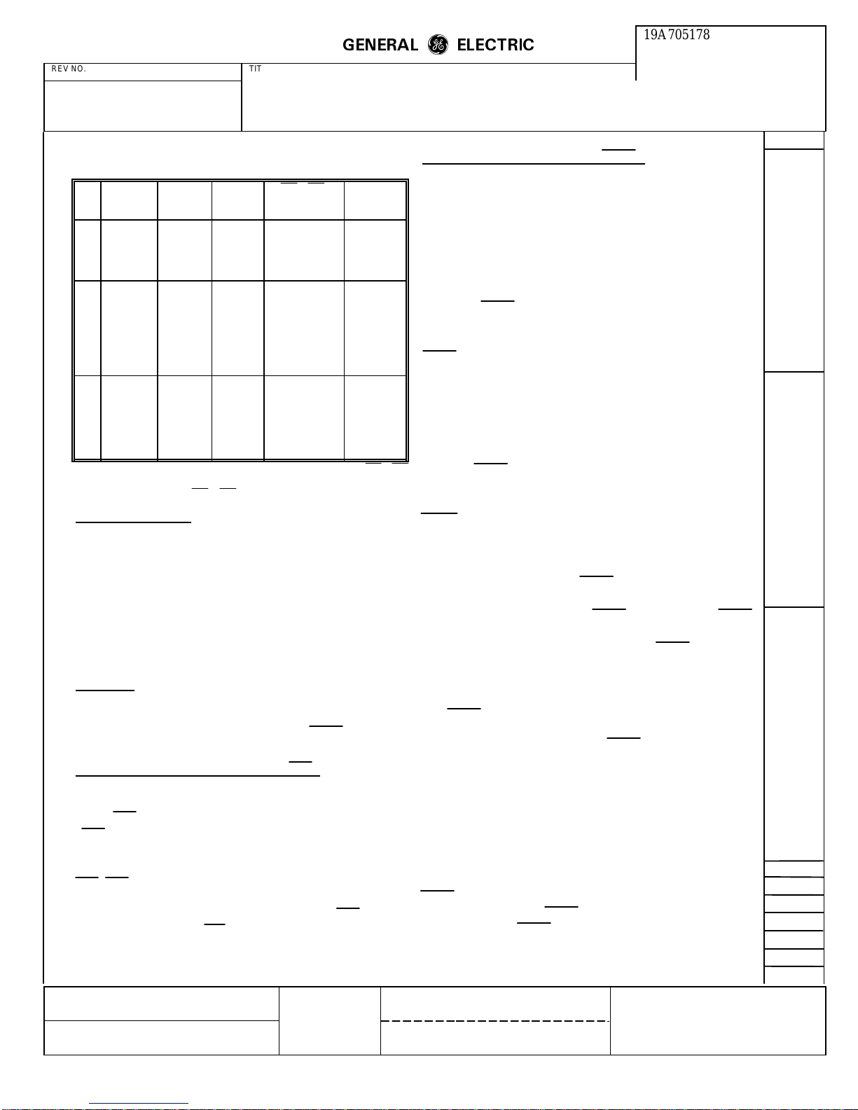
A total of 20 selectable turn-on sequences can be generated
as defined in the following table:
Transmit Level
The transmitter output level is accurate to ±1.0 dB and is
programmable from -l.0 dBm to -l5.0 dBm in 2dB steps.
MADE BY
R Sager
ISSUED
Nov. 19, 1986
APPROVALS
DCB
11-18-86
M. R. P. D.
LYNCHBURG
DIV OR DEPT.
LOCATION
19A705178
CONT ON SHEET
13
L30
PRINTS TO
SH NO.
12
Page 13
REV NO. TITLE
ROCKWELL MODEM TEST
SPECIFICATION/PURCHASE PART DRAWING
CONT ON SHEET SH NO. FIRST MADE FOR
GENERAL
ELECTRIC
m
m
Receive Line Signal Detector (RLSD)
19A705178
CONT ON SHEET
F. C. F. O.
14
SH NO.
13
REVISIONS
No.
1. For short echo protector tone, subtract I55 ms from values of RTS-CTS
2. V.21 (300 bps FSK). RTS-CTS, response time is <35 ms.
V.29
(bps)
FT/9600
1
FT/7200
2
FT/4800
3
4
5
9600
6
7200
7
4800
8
9
10
11
12
13
9600
14
7200
15
4800
16
17
18
19
20
response time.
V.27
bis/ter
(bps)
FT/4800
FT/2400
4800 long
2400 long
4800 short
4800 long
2400 long
4800 short
2400 short
Gearshift
(bps)
2400 short
RTS-CTS
Response Time
(milliseconds) Comments
23
24
23
22
30
253
253
253
708
943
50
152
67
438
438
438
913
1148
255
272
Proprietary
Fast Train
Preceded
by Echo
Protector
Tone for
lines using
echo
suppressers
Turn-Off Sequence
For V.27 bis/ter, V.27FT and 2400/4800 bps Gearshift
configurations, the turn-off sequence consists of
approximately 10 ms of remaining data and scrambled ones
followed by a 20 ms period of no transmitted energy (V.27
bis/ter only). For V.29 and V.29FT, the turn-off sequence
consists of approximately 8 ms of remaining data and
scrambled ones.
Clamping
Response
For Fast Train and Gearshift configurations, the receiver
enters the training state upon detecting a significant
increase in the received signal power. If the received line
signal power is greater than the selected threshold level at
the end of the training state, the receiver enters the Data
state and RLSD is activated. If the received line signal
power is less than the selected threshold level at the end of
the training state, the receiver returns to the idle state and
RLSD is not activated.
Also, in Fast Train and Gearshift configurations, the
receiver initiates the turn-off delay upon detecting a
significant decrease in the received signal power. If the
received signal power is less than the selected threshold at
the end of the turn-off delay, the receiver enters the idle
state and RLSD is deactivated. If the received signal power
were greater than the selected threshold at the end of the
turn-off delay, the receiver returns to the data state and
RLSD is left active.
For CCITT configurations, the receiver enters the training
detection state when the received line sign power crosses
the selected threshold level. RLSD is activated at the end of
the training sequence. For V.21 Channel, a separate
received line signal detector (FRLSD) is provided. FRLSD
is activate when energy above -43 dB is present at the
receiver’s audio input (RXA). The FRLSD off-to-on
response time is 15 ±1.5ms and the on-to-off response time
is 25 ±1.5ms.
Received Data (RXD) is clamped to a constant mark (one)
when the Received Line Signal Detector (RLSD) is off.
Response Times Of Clear To Send (CTS)
The time between the off-to-on transition of Request To
Send (RTS) and the off-to-on transition of Clear to Send
(CTS) is dictated by the length of the training sequence and
the echo protector tone. if used. These times are given in
the Turn-on Sequences table. If training is not enabled.
RTS/CTS delay is less than 2 baud times.
The time between the on-to-off transition of RTS and the
on-to-off transition of CTS in the data state is a maximum
of 2 baud times for all configurations.
MADE BY
R Sager
ISSUED
Nov. 19, 1986
APPROVALS
DCB
11-18-86
The RLSD on-to-off response times are:
RLSD On-To-Off
Configuration Response Time (ms)
V.29 Fast Train 6.5 ±1
V.27 Fast Train 8 ±1
Gearshift 6 ±1
V.29 30 ±9
V.27 bis/ter 10 ±5
RLSD response times are measured with a signal at least 3
dB above the actual RLSD on threshold or at least 5 dB
below the actual RLSD off threshold.
M. R. P. D.
LYNCHBURG
DIV OR DEPT.
LOCATION
19A705178
CONT ON SHEET
14
L30
PRINTS TO
SH NO.
13
Page 14
REV NO. TITLE
ROCKWELL MODEM TEST
SPECIFICATION/PURCHASE PART DRAWING
CONT ON SHEET SH NO. FIRST MADE FOR
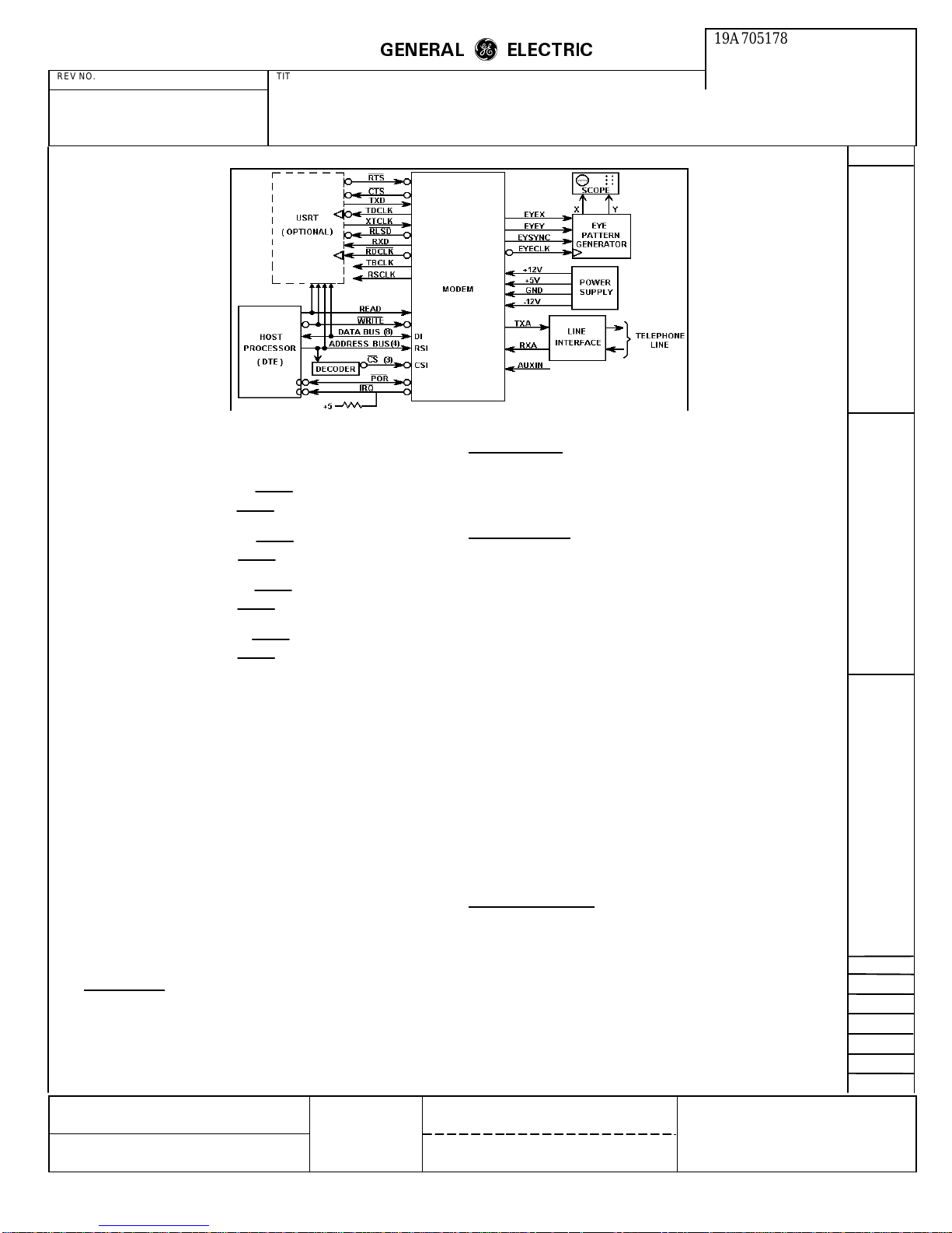
R96FT Functional Interconnect Diagram
Threshold Options
GENERAL
ELECTRIC
m
m
Parallel Mode
19A705178
CONT ON SHEET
F. C. F. O.
15
SH NO.
14
REVISIONS
Four threshold options are provided:
1. Greater than -43 dBm (RLSD on)
Less than -48 dBm (RLSD off)
2. Greater than -33 dBm (RLSD on)
Less than -38 dBm (RLSD off)
3: Greater than -26 dBm (RLSD on)
Less than -31 dBm (RLSD off)
4. Greater than -16 dBm(RLSD on)
Less than -21 dBm (RLSD off)
NOTE
Performance may be at a reduced level when the
received signal is less than -43 dBm.
For CCITT configurations. a minimum hysteresis action of
2dB exists between the actual off-to-on and on-to-off
transition levels. The threshold levels and hysteresis action
are measured with unmodulated 2100 Hz tone applied to
the receiver’s audio signal input (RXA)
MODES OF OPERATION
The R96FT has the capability of transferring channel Data
(up to eight bits at a time) via the microprocessor bus.
Mode Selection
For the transmitter, a control bit determines whether the
source of transmitted data is the V.24 interface (serial
mode) or the parallel transmitter data register (parallel
mode).The transmitter automatically defaults to three serial
mode at power-on.
The receiver simultaneously outputs received data via the
V.24 interface and he parallel receiver data register.
In either parallel or serial mode, the R96FT is configured
by the host processor via the microprocessor bus.
INTERFACE CRITERIA
The modem interface comprises both hardware and
software circuits. Hardware circuits are assigned to specific
pins in a 64-pin DlN connector. Software circuits are
assigned to specific bits in a 48-byte interface memory.
Hardware Circuits
The R96FT capable of being operated in either a serial or a
parallel mode of operation.
Serial Mode
The serial mode uses standard V.24 (RS-232-C
compatible) signals to transfer channel data. An optional
USRT device (shown in the Functional Interconnect
Diagram) illustrates this capability.
MADE BY
R Sager
ISSUED
Nov. 19, 1986
APPROVALS
DCB
11-18-86
Signal names and descriptions of the hardware circuits,
including the microprocessor interface, are listed in the
R96FT Hardware Circuits table. In the table, the column
titled "Type" refers to designations found in the Hardware
Circuit Characteristics. The microprocessor interface is
designed to be directly compatible with an 8080
microprocessor. With the addition of a few external logic
gates, it can be made compatible with 6500, 6800 or 68000
microprocessors.
M. R. P. D.
LYNCHBURG
DIV OR DEPT.
LOCATION
19A705178
CONT ON SHEET
15
L30
PRINTS TO
SH NO.
14
Page 15
REV NO. TITLE
ROCKWELL MODEM TEST
SPECIFICATION/PURCHASE PART DRAWING
CONT ON SHEET SH NO. FIRST MADE FOR
R96FT Hardware Circuits
GENERAL
ELECTRIC
m
m
Eye Pattern Generation
19A705178
CONT ON SHEET
F. C. F. O.
16
SH NO.
15
REVISIONS
Name Type Pin No. Description
A. OVERHEAD:
Ground (A)
Ground (D)
+5 volts
+12 volts
-12 volts
POR
B. MICROPROCESSOR INTERFACE:
D7
D6
D5
D4
D3
D2
D1
D0
RS3
RS2
RS1
RS0
CS0
CS1
CS2
READ
WRITE
IRQ
C. V.24 INTERFACE:
RDCLK
TDCLK
XTCLK
RTS
CTS
TXD
RXD
RLSD
D. ANCILLARY CIRCUITS:
RBCLK
TBCLK
FRXD
FRLSD
E. ANALOG SIGNALS:
TXA
RXA
AUXIN
F. DIAGNOSTIC:
EYEX
EYEY
EYECLK
EYESYNC
MADE BY
ISSUED
AGND
DGND
PWR
PWR
PWR
I/OB
I/OA
I/OA
I/OA
I/OA
I/OA
I/OA
I/OA
I/OA
IA
IA
IA
IA
IA
IA
IA
IA
IA
OB
OC
OC
IB
IB
OC
IB
OC
OC
OC
OC
OD
OD
AA
AB
AC
OC
OC
OA
OA
R Sager
Nov. 19, 1986
31C, 32C
3C, 8C, 5A, 10A
19C, 23C, 26C, 30C
15A
12A
13C
1C
1A
2C
CA
3A
4C
4A
5C
6C
6A
7C
7A
10C
9C
9A
12C
11A
11C
21A
23A
22A
25A
25C
24C
22C
24A
26A
27C
16A
17C
31A
32A
30A
15C
14A
14C
13A
Analog Ground Return
Digital Ground Return
+5 Vdc Supply
+12 Vdc Supply
-12 Vdc Supply
Power-on-reset
Data Bus (8 Bits)
Register Select (4 Bits)
Chip Select Chip Select - Receiver
Chip Select - Receiver
Read Enable
Write Enable
Interrupt Request
Receive Data Clock
Transmit Data Clock
External Transmit Clock
Request to Send
Clear to Send
Transmitter Data
Receiver Data
Received Line Signal
Receiver Baud Clock
Transmitter Baud Clock
FSK Receiver Data
FSK Received Line
Transmitter Analog Output
Receiver Analog Input
Auxiliary Analog Input
Eye Pattern Data - X Axis
Eye Pattern Data - Y Axis
Eye Pattern Data
Eye Pattern Synchronizing
Signal
Transmitter Device
Sample Rate Device
Baud Rate Device
Detector
(inverted data)
Signal Detector
APPROVALS
DCB
11-18-86
The four hardware diagnostic circuits, identified in the
following table, allow the user to generate and display an
eye pattern. Circuits EYEX and EYEY serially present eye
pattern data for the horizontal and vertical display inputs
respectively. The 8 bit data words are shifted out most
Significant bit first, clocked by the rising edge of the
EYECLK output. The EYESYNC output is provided for
word synchronization. The falling edge of EYESYNC may
be used to transfer the 8-bit word from the shift register to
a holding register. Digital to analog conversion can then be
performed for driving the X and Y inputs of an
oscilloscope.
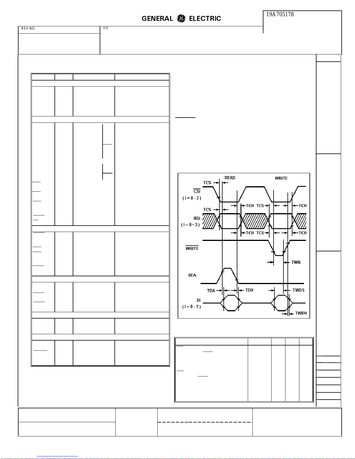
Microprocessor Timing
Microprocessor Interface Timing Diagram
Critical Timing Requirements
Characteristic Symbol Min Max. Units
CSi, RSi setup time prior
to Read or Write TCS 30 — nsec
Data access time after Read TDA — 140 nsec
Data hold time after Read TDH 10 50 nsec
CSi, RSi hold time after
Read or Write TCH 10 — nsec
Write data setup time TWDS 75 — nsec
Write data hold time TWDH 10 — nsec
Write strobe pulse width TWR 75 — nsec
M. R. P. D.
LYNCHBURG
DIV OR DEPT.
LOCATION
19A705178
CONT ON SHEET
16
L30
PRINTS TO
SH NO.
15
Page 16
GENERAL
REV NO. TITLE
ELECTRIC
m
m
CONT ON SHEET
ROCKWELL MODEM TEST
SPECIFICATION/PURCHASE PART DRAWING
19A705178
CONT ON SHEET SH NO. FIRST MADE FOR
F. C. F. O.
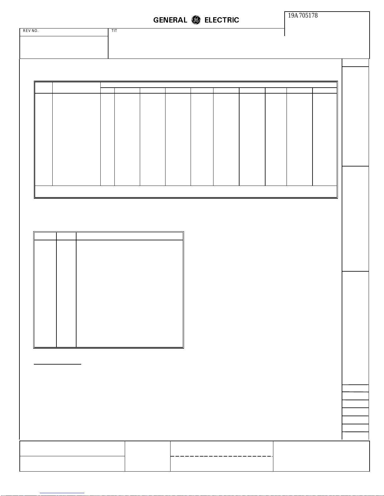
Digital Interface Characteristics
Digital Interface Characteristics
Symbol Parameter Units IA IB IC OA OB OC OD I/O A I/O B
VIHInput Voltage, High V 2.0 Min. 2.0 Min. 2.0 Min. 2.0 Min. 5.25 Max.
VILInput Voltage, Low V 0.8 Max. 0.8 Max. 0.8 Max. 0.8 Max. 0.8 Max.
VOHOutput Voltage, High V 2.4 Min.
VOLOutput Voltage, Low V 0.4 Max. 20.4 Max. 20.4 Max. 20.6 Max.70.4 Max. 20.4 Max.
IINInput Current,
Leakage
IOHOutput Current, High mA -0.1 Max.
IOLOutput Current, Low mA 1.6 Max. 1.6 Max. 1.6 Max.
ILOutput, Current,
Leakage
IPUPull-up Current
(Short Circuit)
CLCapacitive Load pF 5 5 20 10 40
CDCapacitive Drive pF 100 100 100 100 100
Circuit type TTL TTL
Notes 1. I Load = -100 µA 3. I Load = -40 µA 5. I Load = 0.36 mA 7. I Load = 2.0 mA
2. I Load = 1.6 mA 4. V
µA±
µ
A
µ
A
2.5 Max.
-240 Max.
-10 Min.
w/Pull-up
= 0.4 to 2.4 Vdc, VCC = 5.25 Vdc 6. I Load = -400 µA
IN
-240 Max.
-10 Min.
TTL
w/Pull-up
Input/Output Type
1
±
10 Max.
-240 Max.
-10 Min.
TTL Open-Drain Open-Drain
w/Pull-up
2.2 Min.62.4 Min. 12.4 Min.
±
2.5 Max.
TTL 3-State
Transceiver
17
2.0 Min.
4
-260 Max.
-100 Min.
Open-Drain
w/Pull-up
3
5
SH NO.
16
REVISIONS
Analog Interface Characteristics
Analog Interface Characteristics
Name Type Characteristics
TXA AA The transmitter output impedance is 604
RXA AB The receiver input impedance is 60K ohm s
AUXIN AC The auxiliary analog input allows access to
ohms ±1%.
±
23%.
the transmitter for the purpose of interacting
with user provided equipment. Because this
is a sampled data input, any signal above
4800 Hz will cause aliasing errors. The input
impedance is 1K ohms, and the gain to
transmitter output is TLVL setting +0.6 dB
-l.4 dB. If unused, this input must be
grounded near the modem connector. If
used, it must be driven from a low
impedance source.
Software Circuits
The R96FT comprises three signal processor chips. Each
of these chips contains 16 registers to which an external
(host) microprocessor has access. Although these registers
are within the modem, they may be addressed as part of the
processor's memory space. The host may read data out of
or write data into these registers. The registers are referred
to as interface memory. Registers in chip 1 update at half
the modem sample rate (4800 bps). Registers in chip 0 and
2 update at the selected baud rate.
MADE BY
ISSUED
R Sager
Nov. 19, 1986
APPROVALS
DCB
11-18-86
When information in these registers is being discussed, the
format Y:Z:Q is used. The chip is specified by Y(0-2), the
register by Z(0-F), and the bit by Q(0-7, 0 = LSB).
Status Control Bits
The operation of the F96FT is affected by a number of
software control inputs These inputs are written into
registers within the interface memory via the host
microprocessor bus. Modem operation is monitored by
various software flags that are read from interface memory
via the host microprocessor bus. All status and control bits
are defined in the Interface Memory table. Bits, designated
by a dash (—) are reserved for modem use only and must
not be changed by the host.
RAM Data Access
The R96FT provides the user with access to much of the
data stored in the modem's memories. This data is useful
for performing certain diagnostic functions
Two RAM access registers in chip 2 allow user access to
RAM locations via the X word registers (2:2 and 2:2) and
the Y word register (2:1 and 2:0). The access code stored
in RAM ACCESS X (2:5) selects the source of data for
RAM DATA XM and RAM DATA XL (2:3 and 2:2).
Similarly, the access code stored in RAM ACCESS Y (2:4)
selects the source of data for RAM DATA Y and RAM
DATA YL(2:1 and 2:0).
M. R. P. D.
LYNCHBURG
DIV OR DEPT.
LOCATION
19A705178
CONT ON SHEET
17
L30
PRINTS TO
SH NO.
16
Page 17
GENERAL
REV NO. TITLE
ROCKWELL MODEM TEST
CONT ON SHEET SH NO. FIRST MADE FOR
Reading of diagnostic RAM data is performed by storing
the necessary access codes in 2:5 and 2:4, reading 2:0 to
reset the associated data available bit (2:E:0), then waiting
for the data available bit to return to a one. Data is now
valid and may be read from 2:3 through 2:0.
An additional diagnostic is supplied by the sample rate
processor (chip 1). Registers 1:2 and 1:3 supply a 16 bit
AGC Gain Word. These two diagnostic data registers are
updated at the sample rate during the data state and may be
read by the host processor asynchronously.
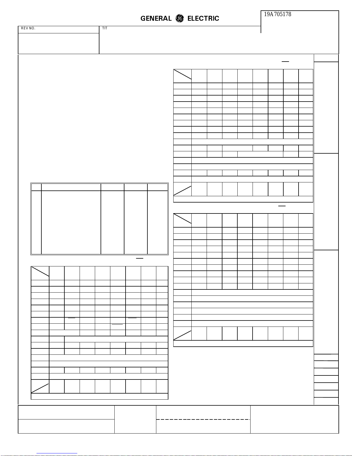
RAM Access Codes
The RAM access codes defined in the following table
allow the host processor to read diagnostic information
within the modem.
Baud Rate Processor (Chip 2) RAM Access Codes
No. Function X Access Y Access Register
1 Equalizer Input C0 40 0,1,2,3
2 Equalizer Tap Coefficients 81-A0 01-20 0,1,2,3
3 Unrotated Equalizer Output E1 61 0,1,2,3
4 Rotated Equalizer Output E2 62 0,1,2,3
5 Decision Points
(Ideal Data Points)
6 Error Vector E5 65 0,1,2,3
7 Rotation Angle A7 Not Used 2,3
8 Frequency Correction A5 Not Used 2,3
9 Eye Quality Monitor (EQM) AC Not Used 2,3
Receiver Interface Memory Chip 1 (CS1)
Bit
Register
D ————————
C ————————
Register
NOTE: (—) indicates reserved for modem use only.
MADE BY
ISSUED
76543210
F ————————
E RIA — — — RSB RIE — RDA
B ————————
A ————————
9 — FED — — — CDET — —
8 — — — — P2DET — — —
7 RTH DDIS — — RCF RDIS —
6 TOD RECEIVER CONFIGURATION
5 ————————
4 ————————
3 AGC GAIN WORD (MSB)
2 AGC GAIN WORD (LSB)
1 ————————
0 RECEIVER DATA
76543210
Bit
R Sager
Nov. 19, 1986
SPECIFICATION/PURCHASE PART DRAWING
E8 68 0,1,2,3
APPROVALS
DCB
11-18-86
ELECTRIC
m
m
Transmitter Interface Memory Chip 0 (CS0)
Bit
Register
Register
NOTE: (—) indicates reserved for modem use only.
76543210
F ————————
E TIA — — — TSB TIE — TBA
D ————————
C ————————
B ————————
A ————————
9 FSKT ASCR — — TCF DDEE — —
8 ————————
7 RTS TTDIS SDIS MHLD EPT TPDM XCEN SEPT
6 TRANSMITTER CONFIGURATION
5 — — CEQ LAEN LDEN A3L D3L
4 L3ACT L4ACT L4HG TLVL L2ACT LCEN
3 FREQM
2 FREQL
1 ————————
0 TRANSMITTER DATA
76543210
Bit
Receiver Interface Memory Chip 2 (CS2)
Bit
Register
Register
NOTE: (—) indicates reserved for modem use only.
M. R. P. D.
LYNCHBURG
76543210
F ————————
E RBIA — — — — RBIE — RBDA
D ————————
C ————————
B ————————
A ————————
9 ————————
8 ————————
7 ————————
6 ————————
5 RAM ACCESS X
4 RAM ACCESS Y
3 RAM DATA XM
2 RAM DATA XL
1 RAM DATA YM
0 RAM DATA YL
76543210
Bit
DIV OR DEPT.
LOCATION
19A705178
CONT ON SHEET
F. C. F. O.
19A705178
CONT ON SHEET
18
18
SH NO.
17
REVISIONS
L30
PRINTS TO
SH NO.
17
Page 18
REV NO. TITLE
ROCKWELL MODEM TEST
SPECIFICATION/PURCHASE PART DRAWING
CONT ON SHEET SH NO. FIRST MADE FOR
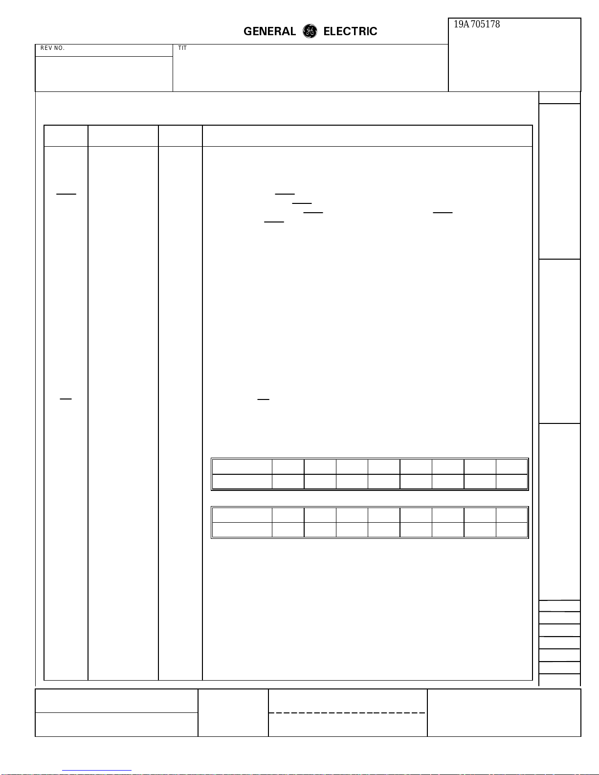
R96FT Interface Memory Definitions
GENERAL
ELECTRIC
m
m
19A705178
CONT ON SHEET
F. C. F. O.
19
SH NO.
18
REVISIONS
Mnemonic Name
ASCR Append Scrambled
Ones
A3L Amplitude 3-Link
Select
CDET Carrier Detector 1:9:2 When zero, status bit CDET indicates that passband energy is being detected, and that a training
CEQ Cable Equalizer 0:5:(4,5) The CEQ Control field simultaneously controls amplitude compromise equalizers in both the transmit
DDEE Digital Delay
Equalizer Enable
DDIS Descramble Disable 1:7:5 When control bit DDIS is a one, the receiver descrambler circuit is removed from the data path.
D3L Delay 3-Link Select 0:5:0 See LDEN.
EPT Echo Protector
Tone
FED Fast Energy
Detector
(None) FREQL/FREQM 0:2:0-7
Memory
Location Description
0:9:6 When control bit ASCR is a one, one baud of scrambled marks is included in the V.29 FT and V.27
0:5:1 See LAEN.
0:9:2 When control bit DDEE is a one, a fourth order digital delay equalizer is inserted in the transmit path.
0:7:3 When control bit EPT is a one, an unmodulated carrier is transmitted for 185 ms (optionally 30 ms)
1:9:6 When status bit FED is a zero, it indicates that energy above the receiver threshold is present in the
0:3:0-7
FT training sequences The RTS-CTS delay is thus extended by one baud per when ASCR is a one.
sequence is not in process. CDET goes to a zero at the start of the data state, and returns to a one at
the end of the received signal. CDET activates up to 1 baud time before RLSD and deactivates within
2 baud times after RLSD.
and receive paths. The following table lists the possible cable equalizer selection codes:
CEQ Cable Length (0.4 mm diameter)
0 0.0
1 1.8 km
2 3.6 km
3 7.2 km
followed by 20 ms of no transmitted energy at the start of transmission. This option is available in the
V.27 and V.29 configurations, although it is not specified in the CCITT V.29 Recommendation.
passband
The host processor conveys tone generation data to the transmitter by writing a 16-bit data word to the
FREQL and FREQM registers in the interface memory space, as shown below:
FREQM Register (0:3)
Bit:
Data Word:
76543210
15
2
14
2
13
2
12
2
11
2
10
2
9
2
8
2
FSKT FSK Transmitter
MADE BY
ISSUED
Configuration
K P Dotson 11-19-86
Nov. 19, 1986
0:9:7 The V.21 Channel 2 (300 bps synchronous FSK) transmitter configuration is selected by setting the
FREQL Register (0:2)
Bit:
Data Word:
The frequency number (N) determines the frequency (F) as follows:
F = (0.146486) (N) Hz ±0.01%
Hexadecimal frequency numbers (FREQL, FREQM) for commonly generated tones are given below:
FSKT control bit to a one (see TSB). While set to a one, this control bit overrides the configuration
selected by the control code in register 0:6. The FSK data may be transmitted in parallel mode or in
serial mode (see TPDM).
APPROVALS
DCB
76543210
7
2
Frequency (Hz) FREQM FREQL
462 0C 52
1100 1D 55
1650 2C 00
1850 31 55
2100 38 00
M. R. P. D.
6
2
5
2
4
2
DIV OR DEPT.
3
2
2
2
1
2
19A705178
0
2
11-18-86
LYNCHBURG
LOCATION
CONT ON SHEET
19
L30
PRINTS TO
SH NO.
18
Page 19
REV NO. TITLE
ROCKWELL MODEM TEST
SPECIFICATION/PURCHASE PART DRAWING
CONT ON SHEET SH NO. FIRST MADE FOR
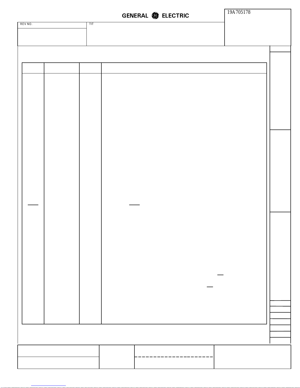
R96FT Interface Memory Definitions (Continued)
GENERAL
ELECTRIC
m
m
19A705178
CONT ON SHEET
F. C. F. O.
20
SH NO.
19
REVISIONS
Mnemonic Name
LAEN Link Amplitude
Equalizer Enable
LCEN Loop Clock Enable 0:4:0 When control bit LCEN is a one, the transmitter clock tracks the receiver clock.
LDEN Link Delay
Equalizer Enable
L2ACT Remote Digital
Loopback Activate
L3ACT Local Analog Loop-
back Activate
L4ACT Remote Analog
Loopback Activate
L4HG Loop 4 High Gain 0:4:5 When control bit L4HG is a one, the loop 4 variable gain amplifier is set for +16 dB, and when at zero
MHLD Mark Hold 0:7:4 When control bit MHLD is a one, the transmitter input data stream is forced to all marks (ones).
P2DET Period 2 Detector 1:8:3 When status bit P2DET is a zero, it indicates that a period 2 sequence has been detected. This bit sets
(None) RAM Access X 2:5:0-7 Contains the RAM access code used in reading chip 2 RAM locations via word X (2:3 and 2:2)
(None) RAM Access Y 2:5:0-7 Contains the RAM access code used in reading chip 2 RAM locations via word Y (2:3 and 2:2)
(None) RAM Data XL 2:2:0-7 Least significant byte of 16-bit word X used in reading RAM locations in chip 2.
(None) RAM Data XM 2:3:0-7 Most significant byte of 16-bit word X used in reading RAM locations in chip 2.
(None) RAM Data YL 2:0:0-7 Least significant byte of 16-bit word Y used in reading RAM locations in chip 2.
(None) RAM Data YM 2:1:0-7 Most significant byte of 16-bit word Y used in reading RAM locations in chip 2.
RBDA Receiver Baud
Data Available
RBIA Receiver Baud
Interrupt Active
RBIE Receiver Baud
Interrupt Enable
RCR Receiver Carrier
Frequency
Memory
Location Description
0:5:3 The link amplitude equalizer enable and select bits control an amplitude compromise equalizer in the
receive path according to the following table:
LAEN A3L Curve Matched
0 X No Equalizer
1 0 U.S. Survey Long
1 1 Japanese 3-Link
0:5:2 The link delay equalizer enable and select bits control a delay compromise equalizer in the receiver
path according to the following table:
LDEN D3L Curve Matched
0 X No Equalizer
1 0 U.S. Survey Long
1 1 Japanese 3-Link
0:4:1 When control bit L2ACT is a one, the receiver digital output is connected to the transmitter digital
input in accordance with CCITT Recommendation V.54 loop 2.
0:4:7 When control bit L3ACT is a one, the transmitter analog output is coupled to the receiver analog input
through an attenuator in accordance with CCITT Recommendation V.54 loop 3.
0:4:6 When control bit L4ACT is a one, the receiver analog input is connected to the transmitter analog
output through a variable gain amplifier in a manner similar to CCITT Recommendation V.54 loop 4.
the gain is zero dB.
to a one at the start of the period N sequences. This bit is only significant for CCITT V.29 and V.27
bis/ter configurations.
2:E:0 Status bit RBDA goes to a one when the receiver writes data into register 2:0. The bit goes to a zero
when the host processor reads data from register 2:0.
2:E:7 This status bit is a one whenever the receiver baud rate device is driving IRQ low.
2:E:2 When the host processor writes a one in the RBIE control bit, the IRQ line of the hardware interface is
driven to zero when status bit RBDA is a one.
1:7:2 Control bit RCF selects the demodulator carrier frequency for V.29FT configurations as follows:
RCF Demodulator Carrier Frequency
0 1700 Hz
1 1800 Hz
L30
MADE BY
K P Dotson 11-19-86
ISSUED
Nov. 19, 1986
APPROVALS
DCB
11-18-86
M. R. P. D.
LYNCHBURG
DIV OR DEPT.
LOCATION
19A705178
CONT ON SHEET
20
PRINTS TO
SH NO.
19
Page 20
REV NO. TITLE
ROCKWELL MODEM TEST
SPECIFICATION/PURCHASE PART DRAWING
CONT ON SHEET SH NO. FIRST MADE FOR
R96FT Interface Memory Definitions (Continued)
GENERAL
ELECTRIC
m
m
19A705178
CONT ON SHEET
F. C. F. O.
21
SH NO.
20
REVISIONS
Mnemonic Name
(None) Receiver
Configuration
Location Description
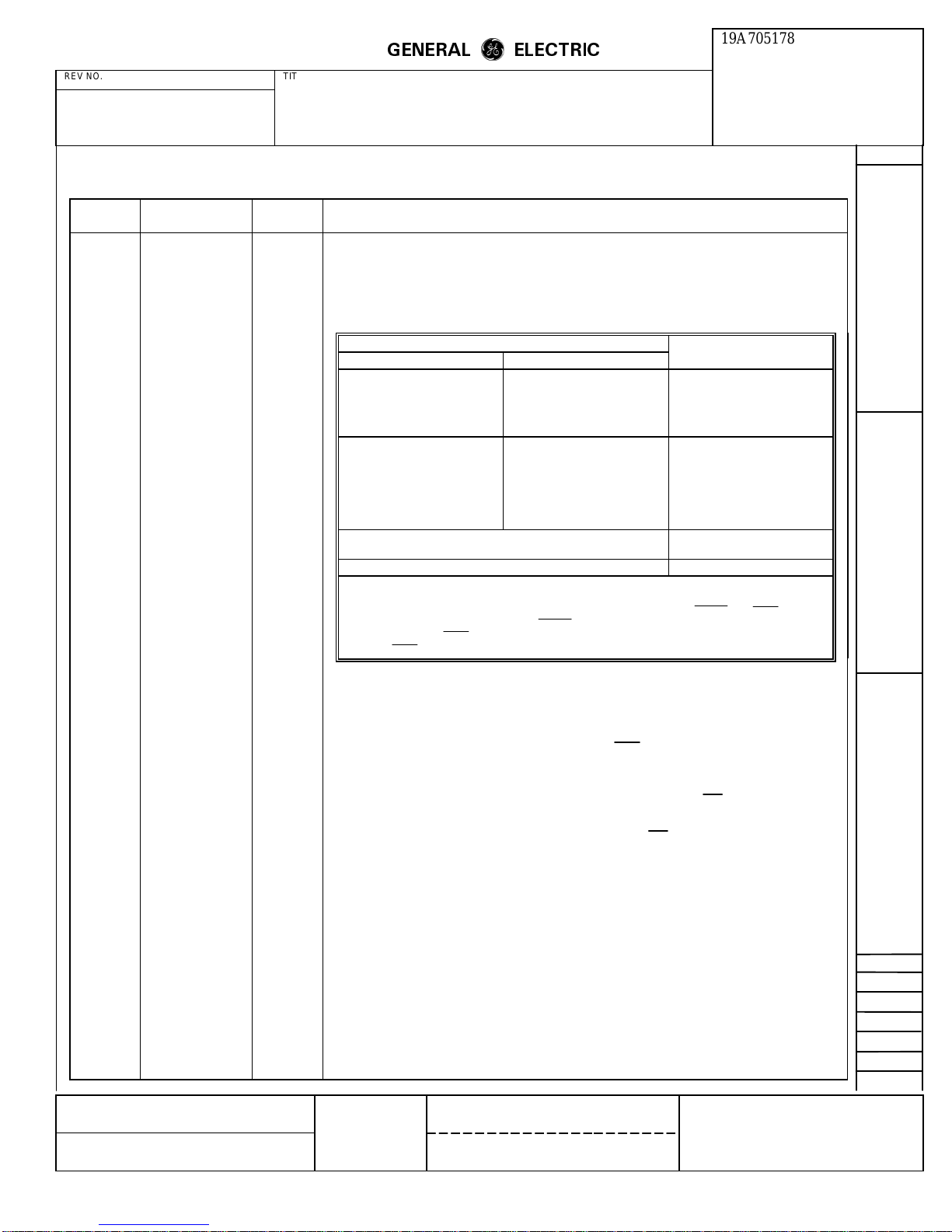
1:6:0-6
The host processor configures the receiver by writing a control code into the receiver configuration
field in the interface memory space (see RSB).
The receiver must be disabled prior to changing configurations. See RDIS.
Note:
Receiver Configuration Control Codes
Control codes for the modem receiver configuration are:
Memory
Configuration
V.29 V.27 bis/ter Configuration Code (Hex)
61
41
1C
1A
19
0A
09
14
12
11
22
21
02
01
1
1
FT/9600
FT/7200
FT/4800
FT/4800
FT/2400
9600
7200
4800
4800 long
2400 long
4800 short
2400 short
2400/4800 bps Gearshift/V.29 descrambler
2400/4800 bps Gearshift/V.27 bis/ter descrambler
V.21 Channel 2 See Note 2
1. The Receiver Configuration code automatically changes from a hex 61 (or hex 41) to a hex 64 (or
hex 44) when the receiver transitions from the 2400 bps data state to the 4800 bps data state.
2. The FSK receiver is active at all times. Two ancillary hardware circuits, FRLSD and FRXD, are
supplied for FSK message reception. FRLSD is described under the Received Line Signal
Detector section. FRXD provides inverted FSK received data. Timing extraction must be performed
on the FRXD signal externally as no FSK receiver data clock is provided by the R96FT.
(None) Receiver Data 1:0:0-7 The host processor obtains channel data from the receiver in the parallel data mode by reading a data
byte from the receiver data register. The data is divided on baud boundaries as is the transmitter data.
RDA Receiver Data
Available
1:E:0 Status bit RDA goes to a one when the receiver writes data to register 1:0. RDA goes to a zero when
the host processor reads data from register 1:0.
RDIS Receiver Disable 1:7:1 When control bit RDIS is a one, the receiver is disabled, RLSD is turned off and RXD is clamped to
all marks. This bit can be used to squelch the receiver during half duplex transmissions over two
wires. This bit must be set to a one prior to changing the receiver configuration.
RIA Receiver Interrupt
1:E:7 This status bit is a one whenever the receiver sample rate device is driving IRQ to zero.
Active
RIE Receiver Interrupt
Enable
1:E:2 When the host processor writes a one in the RIE control bit, the IRQ line of the hardware interface is
driven to zero when status bit RDA is a one.
RSB Receiver Setup Bit 1:E:3 When the host processor changes the receiver configuration or the RTH field, the host processor must
write a one in the RSB control bit. RSB goes to zero when the changes become effective
RTH Receiver Threshold
Field
1:7:6,7 The receiver energy detector threshold is set by the RTH field according to the following codes (see
RSB):
RTH RLSD On RLSD Off
0
1
2
3
43 dBm
≥
33 dBm
≥
26 dBm
≥
16 dBm
≥
48 dBm
≥
38 dBm
≥
31 dBm
≥
21 dBm
≥
RTS Request-to-Send 0:7:7 When control bit RTS goes to a one, the modem begins a transmit sequence. It continues to transmit
until RTS is reset to zero, and the turn-off sequence has been completed. This input bit parallels the
operation of the hardware RTS control input. These inputs are OR’ed by the modem.
MADE BY
ISSUED
K P Dotson 11-19-86
Nov. 19, 1986
APPROVALS
DCB
11-18-86
M. R. P. D.
LYNCHBURG
DIV OR DEPT.
LOCATION
19A705178
CONT ON SHEET
21
L30
PRINTS TO
SH NO.
20
Page 21
REV NO. TITLE
ROCKWELL MODEM TEST
SPECIFICATION/PURCHASE PART DRAWING
CONT ON SHEET SH NO. FIRST MADE FOR
R96FT Interface Memory Definitions (Continued)
GENERAL
ELECTRIC
m
m
19A705178
CONT ON SHEET
F. C. F. O.
22
SH NO.
21
REVISIONS
Mnemonic Name
Location Description
SDIS Scrambler Disable 0:7:5 When control bit SDIS is a one, the transmitter scrambler circuit is removed from the data path.
Memory
SEPT Short Echo
Protector Tone
TBA Transmitter Buffer
Available
TCF Transmitter Carrier
Frequency
0:7:0 When control bit SEPT is a one, the echo protector disable tone is 30 ms long rather than 185 ms
(See TSB)
0:E:0 This status bit resets to zero when the host processor writes data to transmitter data register 0:0. When
the transmitter empties register 0:0, this bit sets to a one.
0:9:3 Control bit TCF selects the modulator carrier frequency for V.29FT configurations as follows:
TCF Modular Carrier Frequency
0 1700 Hz
1 1800 Hz
TIA Transmitter
0:E:7 This status bit is a one whenever the transmitter is driving IRQ to a zero.
Interrupt Active
TIE Transmitter
Interrupt Enable
TLVL Transmitter Level
Field
0:E:2 When the host processor writes a one in control bit TIE, the IRQ line of the hardware interface is
driven to zero when status bit TBA is at a one.
0:4:2-4 The transmitter analog output level is determined by eight TLVL codes, as follows:
TLVL Transmitter Analog Output
0 -1 dBm ± 1 dB
1 -3 dBm ± 1 dB
2 -5 dBm ± 1 dB
3 -7 dBm ± 1 dB
4 -9 dBm ± 1 dB
5 -11 dBm ± 1 dB
6 -13 dBm ± 1 dB
7 -15 dBm ± 1 dB
*Each step above is a 2 dB change ±0.2 dB.
TOD Train-On-Data 1:6:7
When control bit TOD is a one, it enables the train-on-data algorithm to converge the equalizer if the
signal quality degrades sufficiently. When TOD is a one, the modem still recognizes a training
sequence and enters the force train state. A BER of approximately 10
-3
for 0.5 seconds initiates train-
on-data.
TPDM Transmitter Parallel
Data Mode
(None) Transmitter
Configuration
0:7:2
When control bit TPDM is a one, the transmitter accepts data for transmission form the transmitter
data register (0:0) rather than the serial hardware data input.
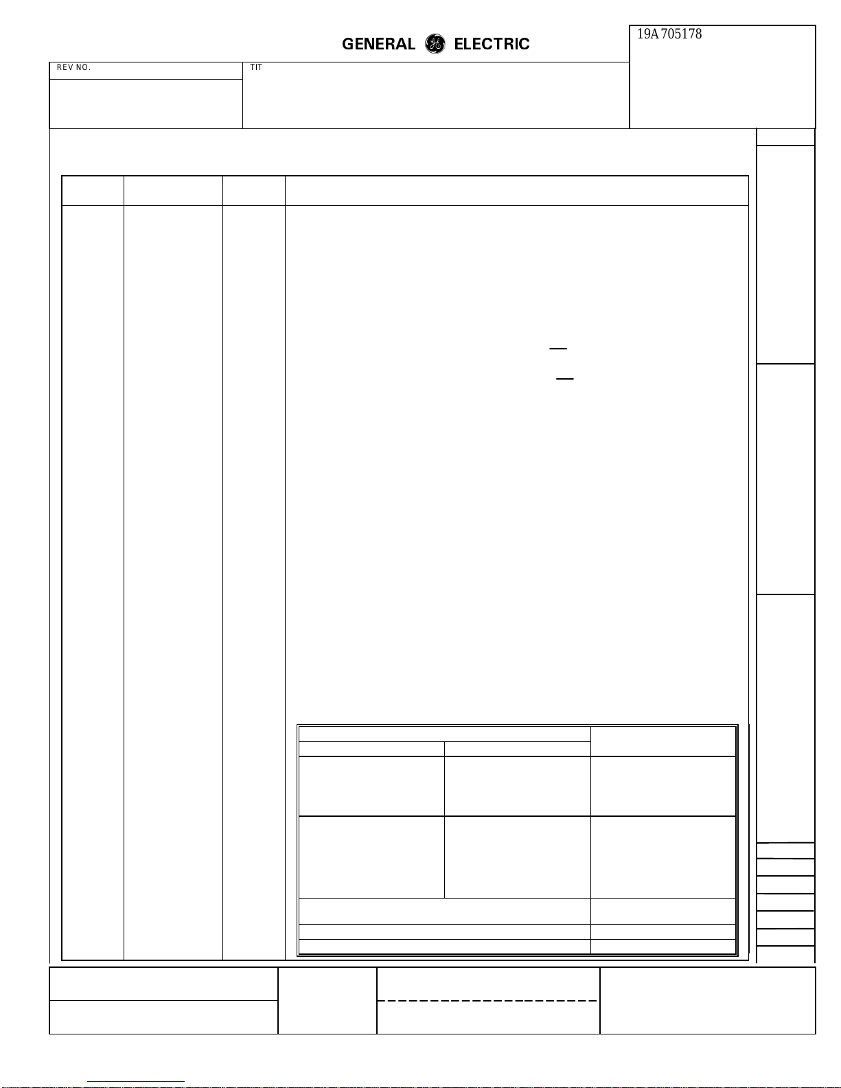
0:6:0-7 The host processor configures the transmitter by writing a control byte into the transmitter
configuration register in its interface memory space. (See TSB)
Transmitter Configuration Control Codes
Control codes for the modem transmitter configurations are:
Configuration
V.29 V.27 bis/ter Configuration Code (Hex)
FT/9600
FT/7200
MADE BY
ISSUED
K P Dotson 11-19-86
Nov. 19, 1986
FT/4800
9600
7200
4800
2400/4800 bps Gearshift/V.29 descrambler
2400/4800 bps Gearshift/V.27 bis/ter descrambler
V.21 Channel 2 See FSKT
Tone transmit 80
APPROVALS
DCB
M. R. P. D.
11-18-86
LYNCHBURG
FT/4800
FT/2400
4800 long
2400 long
4800 short
2400 short
DIV OR DEPT.
LOCATION
19A705178
CONT ON SHEET
61
41
1C
1A
19
0A
09
14
12
11
22
21
02
01
L30
1
1
PRINTS TO
22
SH NO.
21
Page 22
REV NO. TITLE
ROCKWELL MODEM TEST
SPECIFICATION/PURCHASE PART DRAWING
CONT ON SHEET SH NO. FIRST MADE FOR
R96FT Interface Memory Definitions (Continued)
GENERAL
ELECTRIC
m
m
19A705178
CONT ON SHEET
F. C. F. O.
23
SH NO.
22
REVISIONS
Mnemonic Name
(None) Transmitter Data 0:0:0-7 The host processor conveys output data to the transmitter in the parallel mode by writing a data byte
TSB Transmitter Setup 0:E:3 When the host processor changes the transmitter configuration, the SEPT bit or the FSKT bit, the host
TTDIS Transmitter Train
Disable
XCEN External Clock
Enable
POWER-ON INITIALIZATION
When power is applied to the R96FT, a period of 50 to 350
ms is required for power supply settling. The power-onreset signal (POR) remains low during this period.
Memory
Location Description
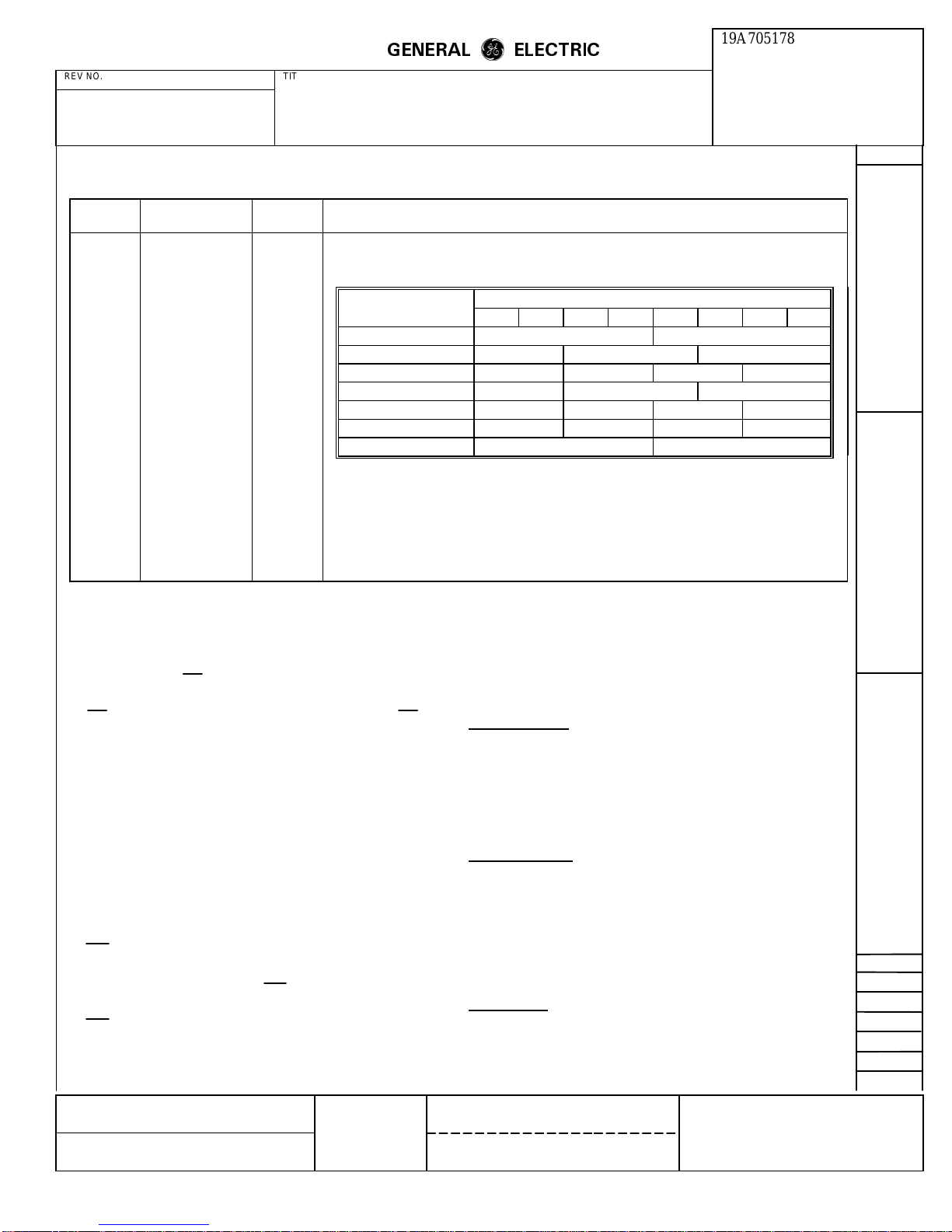
to the transmitter data register. The data is divided on baud boundaries, as follows:
Note: Data is transmitted bit zero first.
Bits
Configuration 76543210
V.29 9600 bps Baud 1 Baud 0
V.29 7200 bps Not Used Baud 1 Baud 0
V.29 4800 bps Baud 3 Baud 2 Baud 1 Baud 0
V.27 4800 bps Not Used Baud 1 Baud 0
V.27 2400 bps Baud 3 Baud 2 Baud 1 Baud 0
2400 bps Gearshift Baud 3 Baud 2 Baud 1 Baud 0
4800 bps Gearshift Baud 1 Baud 0
must write a one in this control bit. TSB goes to a zero when the change becomes effective. Worst
case setup time is 2 baud + turnoff sequence + training (if applicable).
0:7:6 When control bit TTDIS is a one, the transmitter does not generate a training sequence at the start of
transmission. With training disabled, RTS/CTS delay is less than two baud times.
0:7:1 When control bit XCEN is a one, the transmitter timing is established by the external clock supplied
at the hardware input XTCLK, pin 22A.
PERFORMANCE
Whether functioning in V.27, V.29 or the proprietary fast
train configurations, the R96FT provides the user with high
performance.
Approximately 10 ms after the low to high transition of
POR, the modem is ready to be configured, and RTS may
Polling Success
be activated. If the 5 Vdc power supply drops below 3.5
Vdc for more than 30 msec, the POR cycle is generated.
At POR time the modem defaults to the following
configuration: fast train, V.29, 9600 bps, no echo protector
tone, 1700 Hz carrier frequency, scrambled ones segment
disabled, serial data mode, internal clock, cable equalizers
disabled, transmitter digital delay equalizer disabled,
transmitter output level set to -1 dBm ± 1 dB, interrupts
disabled, receiver threshold set to -43 dBm, and train-ondata enabled.
POR can be connected to a user supplied power-on-reset
signal in a wire-or configuration. A low active pulse of 3
In the 9600 bps fast train configuration the modem
approaches a 98% success rate over unconditioned 3002
lines for a signal-to-noise ratio of 26 dB, with a received
signal level of -20 dBm.
Bit Error Rates
The Bit Error Rate (BER) performance of the modem is
specified for a test configuration conforming to that
specified in CCITT Recommendation V.56. Bit error rates
are measured at a received line signal level of -20 dBm as
illustrated.
µsec or more applied to the POR pin causes the modem to
reset. The modem is ready to be configured 10 msec after
POR is removed.
Phase Jitter
At 2400 bps, the modem exhibits a bit error rate of 10-6 or
less with a signal-to-noise ratio of 12.5 dB in the presence
MADE BY
ISSUED
K P Dotson 11-19-86
Nov. 19, 1986
APPROVALS
DCB
11-18-86
M. R. P. D.
LYNCHBURG
DIV OR DEPT.
LOCATION
19A705178
CONT ON SHEET
23
L30
PRINTS TO
SH NO.
22
Page 23

GENERAL
REV NO. TITLE
ROCKWELL MODEM TEST
CONT ON SHEET SH NO. FIRST MADE FOR
of 15° peak-to-peak phase jitter at 150 Hz, or with a signalto-noise ratio of 15 dB in the presence of 30° peak-to-peak
phase jitter at 120 Hz (scrambler inserted).
At 4800 bps (V.27 bis/ter), the modem exhibits a bit error
rate of 10
-6
or less with a signal-to-noise ratio of 19 dB in
the presence of 15° peak-to-peak phase jitter at 60 Hz.
An example of the BER performance capabilities is given
in the following diagrams:
SPECIFICATION/PURCHASE PART DRAWING
ELECTRIC
m
m
CONT ON SHEET
24
F. C. F. O.
19A705178
At 9600 bps, the modem exhibits a bit error rate of 10
-6
or
less with a signal-to-noise ratio of 23 dB in the presence of
10° peak-to-peak phase jitter at 60 Hz. The modem
exhibits a bit error rate of 10
-5
or less with a signal-to-noise
ration of 23 dB in the presence of 20° peak-to-peak phase
jitter at 30 Hz.
SH NO.
23
REVISIONS
Typical BER Performace
Back-to-Back, -20 dBm Receive Signal Level
The BER performance test set-up is shown in the following diagram:
MADE BY
R. Sager
ISSUED
Nov. 19, 1986
APPROVALS
DCB
11-18-86
Typical BER Performace
3002 Unconditioned Line, -20 dBm Receive Signal Level
M. R. P. D.
LYNCHBURG
DIV OR DEPT.
LOCATION
19A705178
CONT ON SHEET
24
SH NO.
L30
PRINTS TO
23
Page 24
GENERAL
REV NO. TITLE
ROCKWELL MODEM TEST
CONT ON SHEET SH NO. FIRST MADE FOR
INTRODUCTION
The R96FAX, R96DP, R48DP, AND R96FT modems
include integrated analog devices using switched capacitor
filters to perform the functions of receiver input bandpass
filtering, transmitter output lowpass filtering, and
compromise equalization. Differences in performance
result form half-duplex (HDX) or full-duplex (FDX)
versions of the integrated analog device.
R96 FILTERS
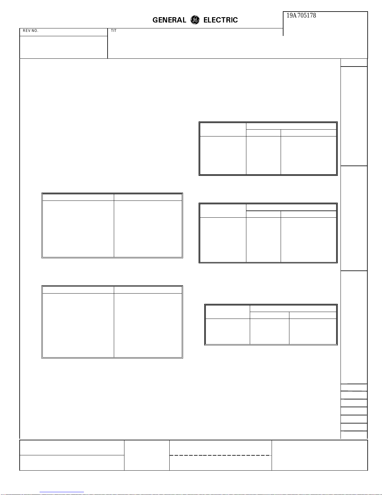
The following tables illustrate the response of the receiver
input bandpass and transmitter output low pass filters
without compromise equalization.
A. Receiver Input Bandpass Filter
Parameter Value
Test signal range 0 dBm to -45 dBm
Passband 400 Hz - 3000 Hz
Passband ripple 0.5 dB max.
Loss below 60 Hz 40 dB min.
Loss above 6000 Hz 40 dB min.
Passband gain
Delay distortion 400 Hz - 1800 Hz Less than 1000 usec
Delay distortion 1800 Hz -
3000 Hz
SPECIFICATION/PURCHASE PART DRAWING
0.0 dB ± 1.0 dB
Less than 150 usec
ELECTRIC
m
m
CONT ON SHEET
25
F. C. F. O.
The following tables illustrate the change in filter response
caused by enabling each of the compromise equalizers
independently.
A. Receiver
1. Link Amplitude Equalizer HDX and FDX.
19A705178
Frequency Gain dB Relative to 1700 Hz
Hz US Long Japanese 3 Link
1000 -0.27 -0.13
1400 -0.16 -0.08
2000 +0.33 +0.16
2400 +1.54 +0.73
2800 +5.98 +2.61
3000 +8.65 +3.43
2. Link Delay Equalizer FDX Only.
Frequency Delay Microseconds Relative to 1700 Hz
Hz US Long Japanese 3 Link
800 -498.1 -653.1
1200 -188.3 -398.5
1600 -15.1 -30.0
1700 +0.0 +0.0
2000 -39.8 +11.7
2400 -423.1 -117.1
2800 -672.4 -546.3
SH NO.
24
REVISIONS
B. Transmitter Output Lowpass Filter
Parameter Value
Test signal 0 dBm to -16 dBm
Passband 400 Hz - 3000 Hz
Passband Gain
Passband ripple 0.5 dB max.
Loss at 3600 Hz 5.5 dB min.
Loss at 7800 Hz 32 dB min.
Loss at 11400 Hz 33.5 dB min.
Loss at 12000 Hz 41 dB min.
Loss above 17400 Hz 45 dB min.
Delay distortion 400 Hz - 3000 Hz Less than 300 usec
MADE BY
R. Sager
ISSUED
Nov. 19, 1986
-1 dB ± 1 dB
APPROVALS
11-18-86
DCB
3. Cable amplitude HDX and FDX.
a. Code 1
M. R. P. D.
LYNCHBURG
Frequency Gain dB Relative to 1700 Hz
Hz HDX FDX
700 -0.99 -0.94
1500 -0.20 -0.24
2000 +0.15 +0.31
3000 +1.43 +1.49
DIV OR DEPT.
LOCATION
19A705178
CONT ON SHEET
25
SH NO.
L30
PRINTS TO
24
Page 25
REV NO. TITLE
ROCKWELL MODEM TEST
SPECIFICATION/PURCHASE PART DRAWING
CONT ON SHEET SH NO. FIRST MADE FOR
b. CODE 2
GENERAL
ELECTRIC
m
m
2. Cable Amplitude HDX and FDX.
19A705178
CONT ON SHEET
F. C. F. O.
Final
SH NO.
25
REVISIONS
Frequency Gain dB Relative to 1700 Hz
Hz HDX FDX
700 -2.39 -2.67
1500 -0.65 -0.74
2000 +0.87 +1.02
3000 +3.06 +3.17
c. CODE 3
Frequency Gain dB Relative to 1700 Hz
Hz HDX FDX
700 -3.93 -3.98
1500 -1.22 -1.20
2000 +1.90 +1.81
3000 +4.58 +4.38
B. Transmitter
1. Link Amplitude Equalizer HDX Only.
Frequency Gain dB Relative to 1700 Hz
Hz US Long Japanese 3 Link
1000 -0.27 -0.13
1400 -0.16 -0.08
2000 +0.33 +0.16
2400 +1.54 +0.73
2800 +5.98 +2.61
3000 +8.65 +3.43
a. CODE 1
b. CODE 2
c. CODE 3
Frequency
Hz
700 -0.99
1500 -0.20
2000 +0.15
3000 +1.43
Frequency
Hz
700 -2.39
1500 -0.65
2000 +0.87
3000 +3.06
Frequency
Hz
700 -3.93
1500 -1.22
2000 +1.90
3000 +4.58
Gain dB Relative
Gain dB Relative
Gain dB Relative
to 1700 Hz
to 1700 Hz
to 1700 Hz
MADE BY
R Sager
ISSUED
Nov. 19, 1986
APPROVALS
DCB
11-18-86
M. R. P. D.
LYNCHBURG
DIV OR DEPT.
LOCATION
19A705178
CONT ON SHEET
Final
L30
PRINTS TO
SH NO.
25
Page 26
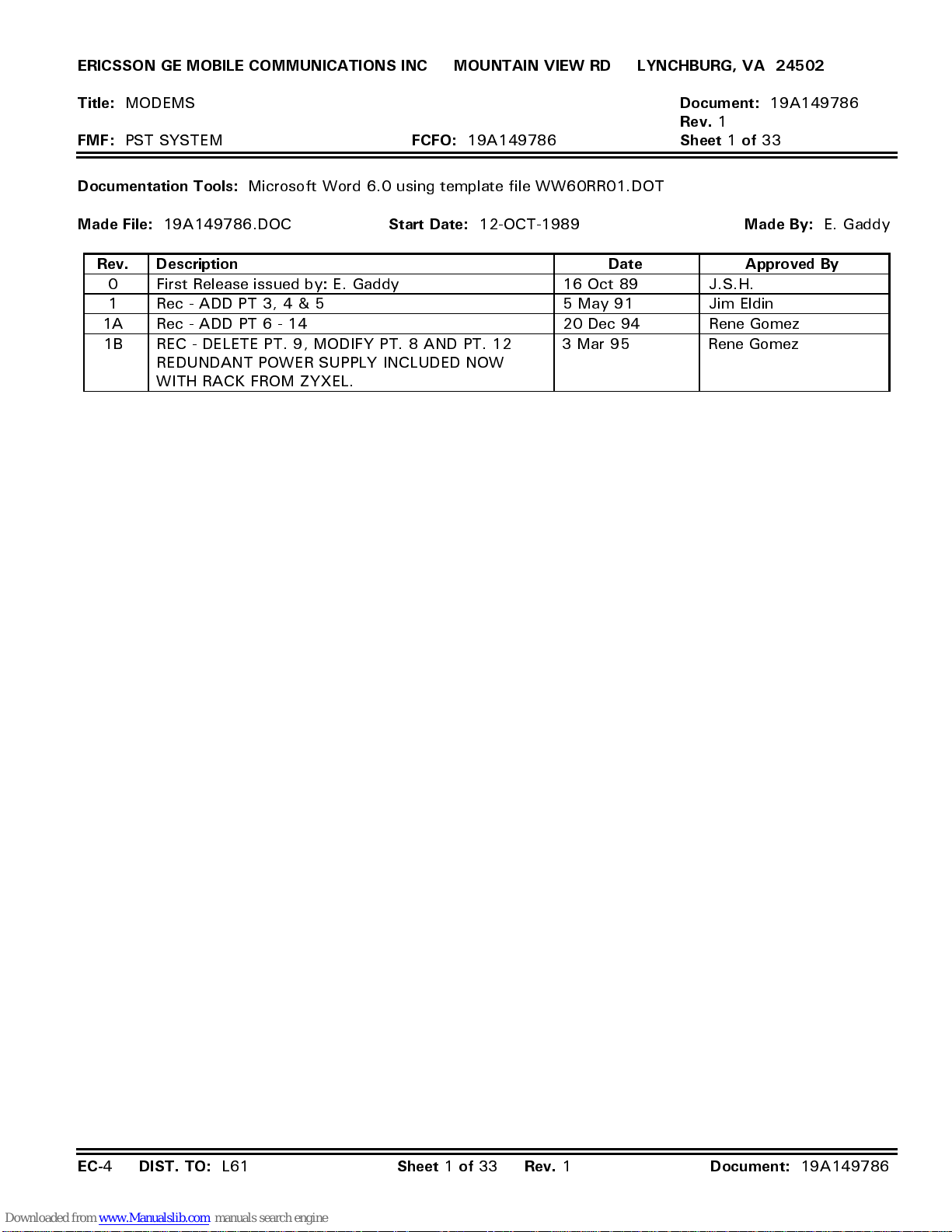
ERICSSON GE MOBILE COMMUNICATIONS INC MOUNTAIN VIEW RD LYNCHBURG, VA 24502
Title:
FMF:
Documentation Tools:
Made File:
MODEMS
PST SYSTEM
19A149786.DOC
FCFO:
19A149786
Microsoft Word 6.0 using template file WW60RR01.DOT
Start Date:
12-OCT-1989
Document:
Rev.
1
Sheet 1 of
Made By:
19A149786
33
Rev. Description Date Approved By
0 First Release issued by: E. Gaddy 16 Oct 89 J.S.H.
1 Rec - ADD PT 3, 4 & 5 5 May 91 Jim Eldin
1A Rec - ADD PT 6 - 14 20 Dec 94 Rene Gomez
1B REC - DELETE PT. 9, MODIFY PT. 8 AND PT. 12
3 Mar 95 Rene Gomez
REDUNDANT POWER SUPPLY INCLUDED NOW
WITH RACK FROM ZYXEL.
E. Gaddy
EC-
4
DIST. TO:
L61
Sheet 1 of 33 Rev.
1
Document:
19A149786
Page 27
ERICSSON GE MOBILE COMMUNICATIONS INC MOUNTAIN VIEW RD LYNCHBURG, VA 24502
Title:
FMF:
MODEMS
PST SYSTEM
FCFO:
19A149786
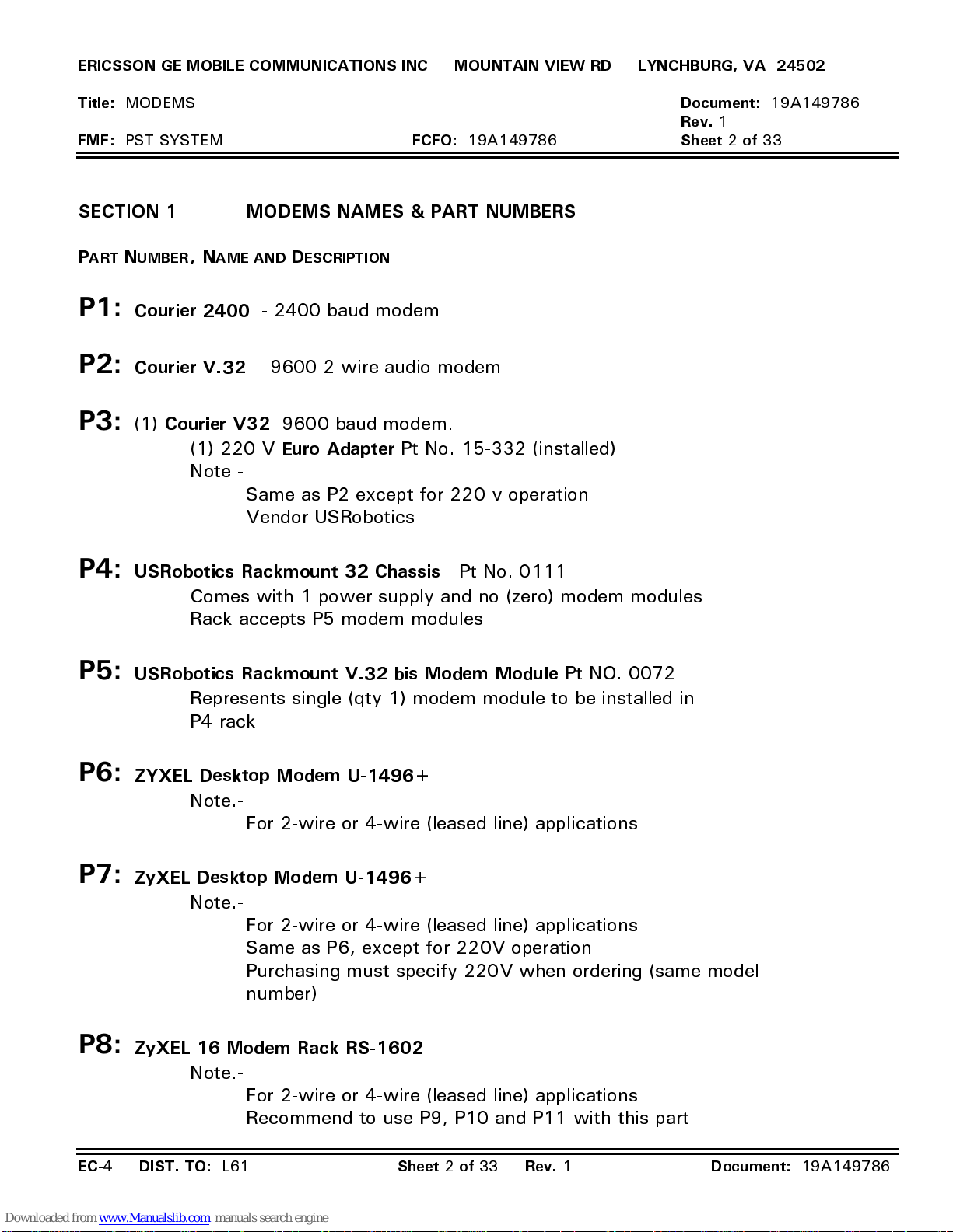
SECTION 1 MODEMS NAMES & PART NUMBERS
ART NUMBER
P
P1:
P2:
P3:
Courier 2400
Courier V.32
(1)
Courier V32
AME AND DESCRIPTION
, N
- 2400 baud modem
- 9600 2-wire audio modem
9600 baud modem.
(1) 220 V
Euro Adapter
Pt No. 15-332 (installed)
Note -
Same as P2 except for 220 v operation
Vendor USRobotics
Document:
Rev.
1
Sheet 2 of
19A149786
33
P4:
P5:
P6:
P7:
USRobotics Rackmount 32 Chassis
Pt No. 0111
Comes with 1 power supply and no (zero) modem modules
Rack accepts P5 modem modules
USRobotics Rackmount V.32 bis Modem Module
Represents single (qty 1) modem module to be installed in
P4 rack
ZYXEL Desktop Modem U-1496+
Note.-
For 2-wire or 4-wire (leased line) applications
ZyXEL Desktop Modem U-1496+
Note.-
For 2-wire or 4-wire (leased line) applications
Same as P6, except for 220V operation
Purchasing must specify 220V when ordering (same model
number)
Pt NO. 0072
P8:
ZyXEL 16 Modem Rack RS-1602
Note.-
For 2-wire or 4-wire (leased line) applications
Recommend to use P9, P10 and P11 with this part
EC-
4
DIST. TO:
L61
Sheet 2 of 33 Rev.
1
Document:
19A149786
Page 28
ERICSSON GE MOBILE COMMUNICATIONS INC MOUNTAIN VIEW RD LYNCHBURG, VA 24502
Title:
FMF:
MODEMS
PST SYSTEM
P10:
P11:
P12:
FCFO:
19A149786
Document:
Rev.
1
Sheet 3 of
19A149786
33
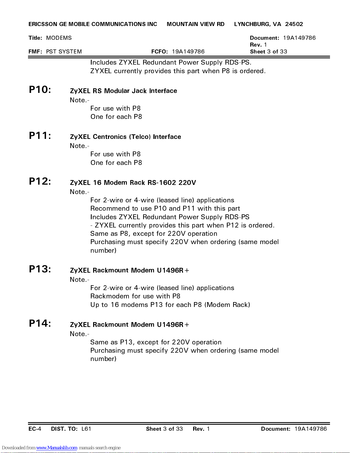
Includes ZYXEL Redundant Power Supply RDS-PS.
ZYXEL currently provides this part when P8 is ordered.
ZyXEL RS Modular Jack Interface
Note.-
For use with P8
One for each P8
ZyXEL Centronics (Telco) Interface
Note.-
For use with P8
One for each P8
ZyXEL 16 Modem Rack RS-1602 220V
Note.-
For 2-wire or 4-wire (leased line) applications
Recommend to use P10 and P11 with this part
Includes ZYXEL Redundant Power Supply RDS-PS
- ZYXEL currently provides this part when P12 is ordered.
Same as P8, except for 220V operation
Purchasing must specify 220V when ordering (same model
number)
P13:
P14:
EC-
4
ZyXEL Rackmount Modem U1496R+
Note.-
ZyXEL Rackmount Modem U1496R+
Note.-
DIST. TO:
For 2-wire or 4-wire (leased line) applications
Rackmodem for use with P8
Up to 16 modems P13 for each P8 (Modem Rack)
Same as P13, except for 220V operation
Purchasing must specify 220V when ordering (same model
number)
L61
Sheet 3 of 33 Rev.
1
Document:
19A149786
Page 29
ERICSSON GE MOBILE COMMUNICATIONS INC MOUNTAIN VIEW RD LYNCHBURG, VA 24502
Title:
FMF:
SECTION 2 US R
MODEMS
PST SYSTEM
OBOTICS
FCFO:
19A149786
V.32. CONFIGURATION INFORMATION
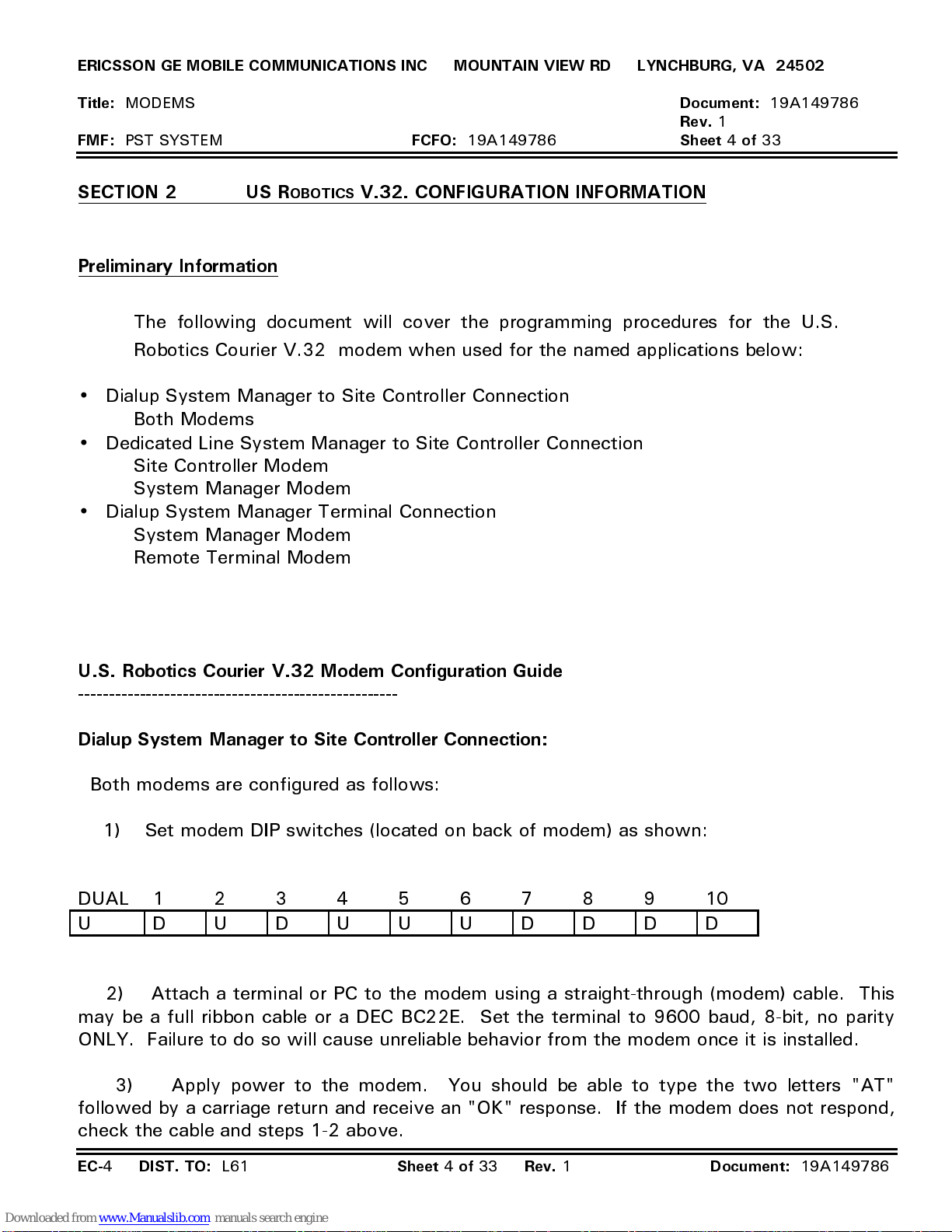
Preliminary Information
The following document will cover the programming procedures for the U.S.
Robotics Courier V.32 modem when used for the named applications below:
•
Dialup System Manager to Site Controller Connection
•
Both Modems
Dedicated Line System Manager to Site Controller Connection
Site Controller Modem
System Manager Modem
•
Dialup System Manager Terminal Connection
System Manager Modem
Remote Terminal Modem
Document:
Rev.
1
Sheet 4 of
19A149786
33
U.S. Robotics Courier V.32 Modem Configuration Guide
----------------------------------------------------
Dialup System Manager to Site Controller Connection:
Both modems are configured as follows:
1) Set modem DIP switches (located on back of modem) as shown:
DUAL 12345678910
U DUDUUUDDDD
2) Attach a terminal or PC to the modem using a straight-through (modem) cable. This
may be a full ribbon cable or a DEC BC22E. Set the terminal to 9600 baud, 8-bit, no parity
ONLY. Failure to do so will cause unreliable behavior from the modem once it is installed.
3) Apply power to the modem. You should be able to type the two letters "AT"
followed by a carriage return and receive an "OK" response. If the modem does not respond,
check the cable and steps 1-2 above.
EC-
4
DIST. TO:
L61
Sheet 4 of 33 Rev.
1
Document:
19A149786
Page 30
ERICSSON GE MOBILE COMMUNICATIONS INC MOUNTAIN VIEW RD LYNCHBURG, VA 24502
Title:
FMF:
MODEMS
PST SYSTEM
FCFO:
19A149786
Document:
Rev.
1
Sheet 5 of
19A149786
33
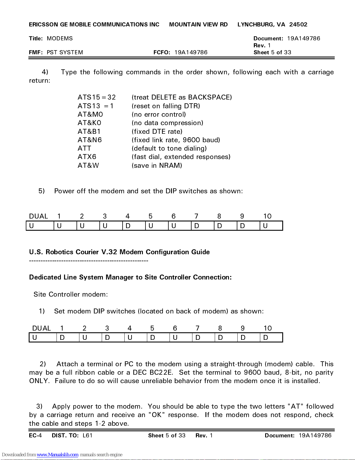
4) Type the following commands in the order shown, following each with a carriage
return:
ATS15=32 (treat DELETE as BACKSPACE)
ATS13 =1 (reset on falling DTR)
AT&M0 (no error control)
AT&K0 (no data compression)
AT&B1 (fixed DTE rate)
AT&N6 (fixed link rate, 9600 baud)
ATT (default to tone dialing)
ATX6 (fast dial, extended responses)
AT&W (save in NRAM)
5) Power off the modem and set the DIP switches as shown:
DUAL 12345678910
U UUUDUUDDDU
U.S. Robotics Courier V.32 Modem Configuration Guide
----------------------------------------------------
Dedicated Line System Manager to Site Controller Connection:
Site Controller modem:
1) Set modem DIP switches (located on back of modem) as shown:
DUAL 12345678910
U DUDUDUDDDD
2) Attach a terminal or PC to the modem using a straight-through (modem) cable. This
may be a full ribbon cable or a DEC BC22E. Set the terminal to 9600 baud, 8-bit, no parity
ONLY. Failure to do so will cause unreliable behavior from the modem once it is installed.
3) Apply power to the modem. You should be able to type the two letters "AT" followed
by a carriage return and receive an "OK" response. If the modem does not respond, check
the cable and steps 1-2 above.
EC-
4
DIST. TO:
L61
Sheet 5 of 33 Rev.
1
Document:
19A149786
Page 31
ERICSSON GE MOBILE COMMUNICATIONS INC MOUNTAIN VIEW RD LYNCHBURG, VA 24502
Title:
FMF:
MODEMS
PST SYSTEM
FCFO:
19A149786
Document:
Rev.
1
Sheet 6 of
19A149786
33
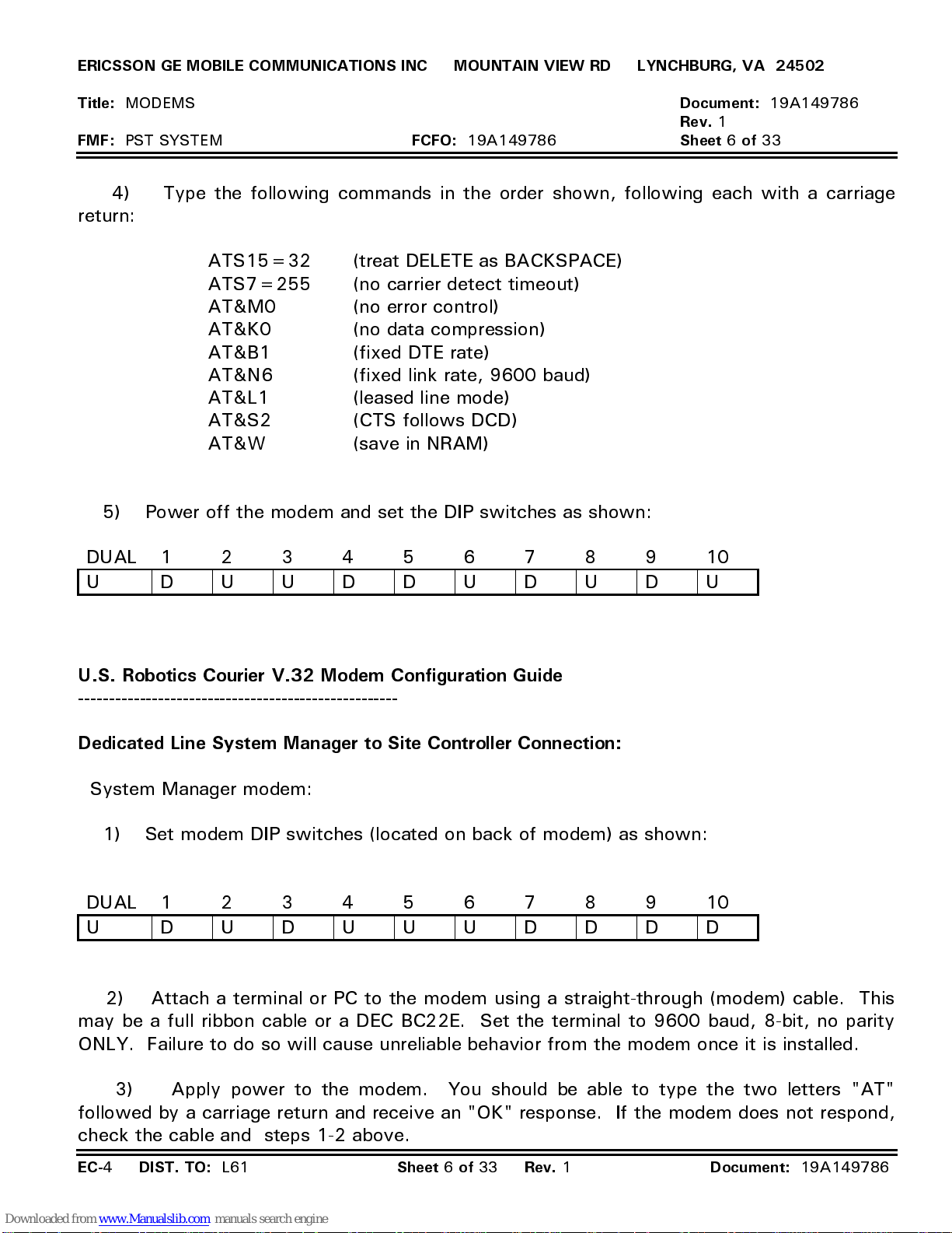
4) Type the following commands in the order shown, following each with a carriage
return:
ATS15=32 (treat DELETE as BACKSPACE)
ATS7=255 (no carrier detect timeout)
AT&M0 (no error control)
AT&K0 (no data compression)
AT&B1 (fixed DTE rate)
AT&N6 (fixed link rate, 9600 baud)
AT&L1 (leased line mode)
AT&S2 (CTS follows DCD)
AT&W (save in NRAM)
5) Power off the modem and set the DIP switches as shown:
DUAL 12345678910
U DUUDDUDUDU
U.S. Robotics Courier V.32 Modem Configuration Guide
----------------------------------------------------
Dedicated Line System Manager to Site Controller Connection:
System Manager modem:
1) Set modem DIP switches (located on back of modem) as shown:
DUAL 12345678910
U DUDUUUDDDD
2) Attach a terminal or PC to the modem using a straight-through (modem) cable. This
may be a full ribbon cable or a DEC BC22E. Set the terminal to 9600 baud, 8-bit, no parity
ONLY. Failure to do so will cause unreliable behavior from the modem once it is installed.
3) Apply power to the modem. You should be able to type the two letters "AT"
followed by a carriage return and receive an "OK" response. If the modem does not respond,
check the cable and steps 1-2 above.
EC-
4
DIST. TO:
L61
Sheet 6 of 33 Rev.
1
Document:
19A149786
Page 32
ERICSSON GE MOBILE COMMUNICATIONS INC MOUNTAIN VIEW RD LYNCHBURG, VA 24502
Title:
FMF:
MODEMS
PST SYSTEM
FCFO:
19A149786
Document:
Rev.
1
Sheet 7 of
19A149786
33
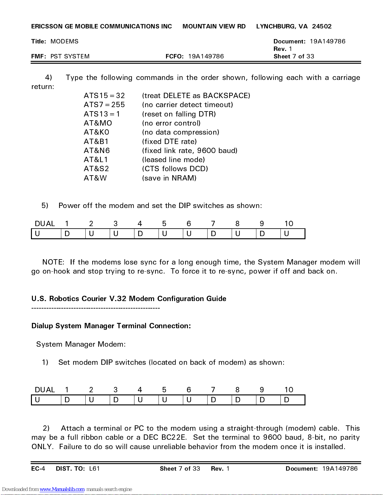
4) Type the following commands in the order shown, following each with a carriage
return:
ATS15=32 (treat DELETE as BACKSPACE)
ATS7=255 (no carrier detect timeout)
ATS13=1 (reset on falling DTR)
AT&MO (no error control)
AT&K0 (no data compression)
AT&B1 (fixed DTE rate)
AT&N6 (fixed link rate, 9600 baud)
AT&L1 (leased line mode)
AT&S2 (CTS follows DCD)
AT&W (save in NRAM)
5) Power off the modem and set the DIP switches as shown:
DUAL 12345678910
U DUUDUUDUDU
NOTE: If the modems lose sync for a long enough time, the System Manager modem will
go on-hook and stop trying to re-sync. To force it to re-sync, power if off and back on.
U.S. Robotics Courier V.32 Modem Configuration Guide
----------------------------------------------------
Dialup System Manager Terminal Connection:
System Manager Modem:
1) Set modem DIP switches (located on back of modem) as shown:
DUAL 12345678910
U DUDUUUDDDD
2) Attach a terminal or PC to the modem using a straight-through (modem) cable. This
may be a full ribbon cable or a DEC BC22E. Set the terminal to 9600 baud, 8-bit, no parity
ONLY. Failure to do so will cause unreliable behavior from the modem once it is installed.
EC-
4
DIST. TO:
L61
Sheet 7 of 33 Rev.
1
Document:
19A149786
Page 33
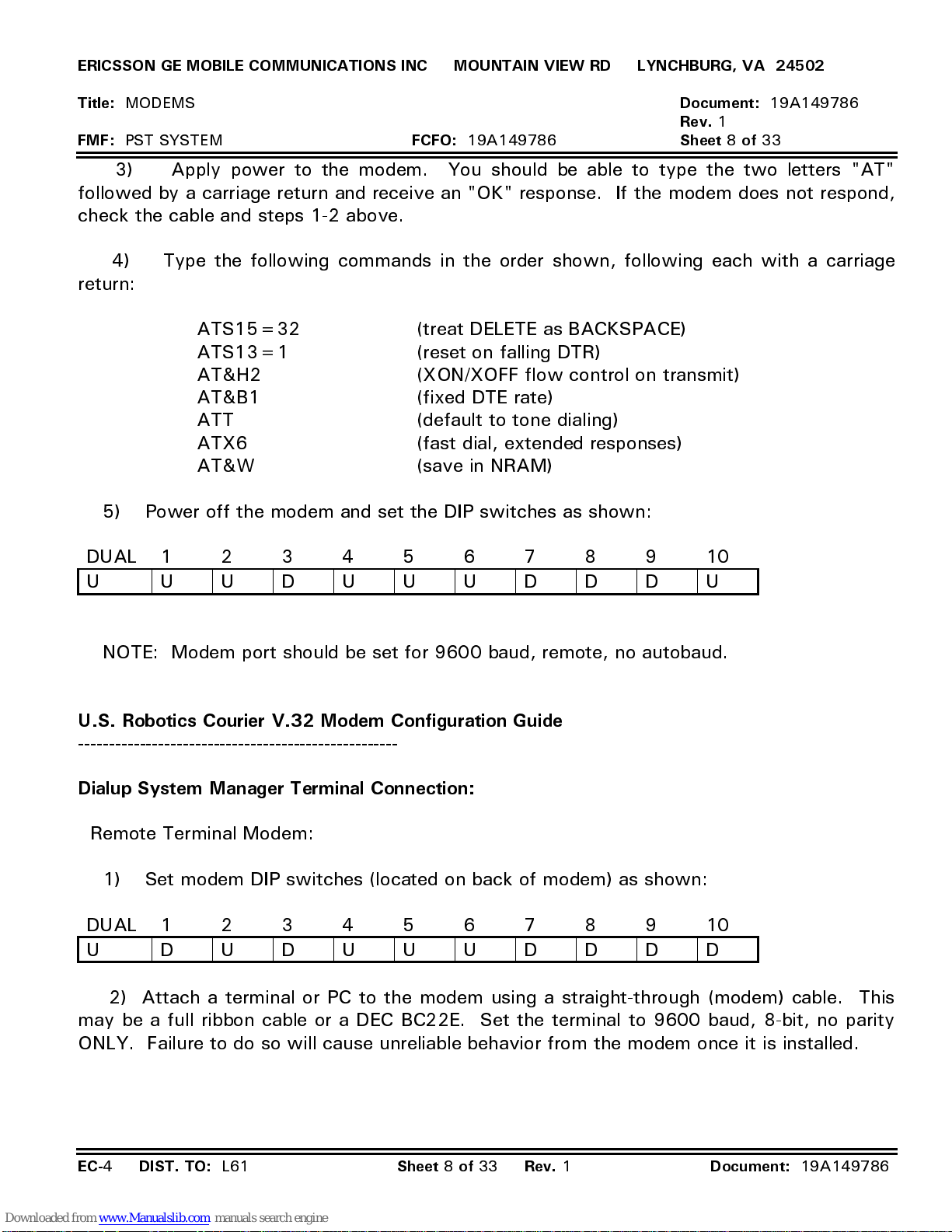
ERICSSON GE MOBILE COMMUNICATIONS INC MOUNTAIN VIEW RD LYNCHBURG, VA 24502
Title:
FMF:
MODEMS
PST SYSTEM
FCFO:
19A149786
Document:
Rev.
1
Sheet 8 of
19A149786
33
3) Apply power to the modem. You should be able to type the two letters "AT"
followed by a carriage return and receive an "OK" response. If the modem does not respond,
check the cable and steps 1-2 above.
4) Type the following commands in the order shown, following each with a carriage
return:
ATS15=32 (treat DELETE as BACKSPACE)
ATS13=1 (reset on falling DTR)
AT&H2 (XON/XOFF flow control on transmit)
AT&B1 (fixed DTE rate)
ATT (default to tone dialing)
ATX6 (fast dial, extended responses)
AT&W (save in NRAM)
5) Power off the modem and set the DIP switches as shown:
DUAL 12345678910
U UUDUUUDDDU
NOTE: Modem port should be set for 9600 baud, remote, no autobaud.
U.S. Robotics Courier V.32 Modem Configuration Guide
----------------------------------------------------
Dialup System Manager Terminal Connection:
Remote Terminal Modem:
1) Set modem DIP switches (located on back of modem) as shown:
DUAL 12345678910
U DUDUUUDDDD
2) Attach a terminal or PC to the modem using a straight-through (modem) cable. This
may be a full ribbon cable or a DEC BC22E. Set the terminal to 9600 baud, 8-bit, no parity
ONLY. Failure to do so will cause unreliable behavior from the modem once it is installed.
EC-
4
DIST. TO:
L61
Sheet 8 of 33 Rev.
1
Document:
19A149786
Page 34
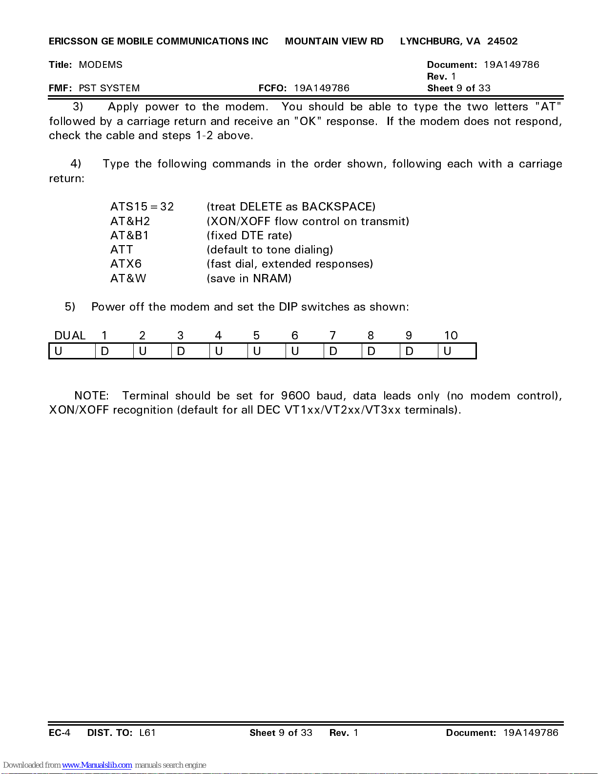
ERICSSON GE MOBILE COMMUNICATIONS INC MOUNTAIN VIEW RD LYNCHBURG, VA 24502
Title:
FMF:
MODEMS
PST SYSTEM
FCFO:
19A149786
Document:
Rev.
1
Sheet 9 of
19A149786
33
3) Apply power to the modem. You should be able to type the two letters "AT"
followed by a carriage return and receive an "OK" response. If the modem does not respond,
check the cable and steps 1-2 above.
4) Type the following commands in the order shown, following each with a carriage
return:
ATS15=32 (treat DELETE as BACKSPACE)
AT&H2 (XON/XOFF flow control on transmit)
AT&B1 (fixed DTE rate)
ATT (default to tone dialing)
ATX6 (fast dial, extended responses)
AT&W (save in NRAM)
5) Power off the modem and set the DIP switches as shown:
DUAL 12345678910
U DUDUUUDDDU
NOTE: Terminal should be set for 9600 baud, data leads only (no modem control),
XON/XOFF recognition (default for all DEC VT1xx/VT2xx/VT3xx terminals).
EC-
4
DIST. TO:
L61
Sheet 9 of 33 Rev.
1
Document:
19A149786
Page 35
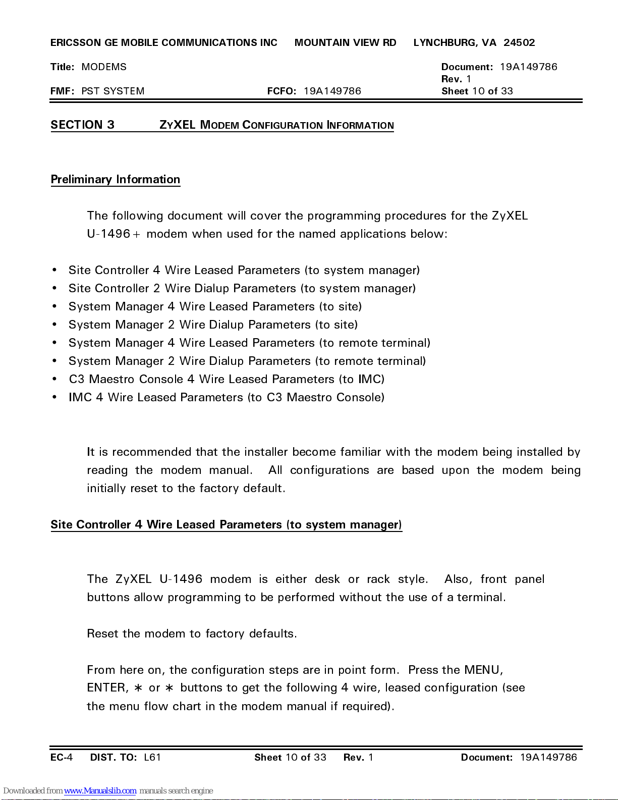
ERICSSON GE MOBILE COMMUNICATIONS INC MOUNTAIN VIEW RD LYNCHBURG, VA 24502
Title:
FMF:
SECTION 3 ZYXEL M
MODEMS
PST SYSTEM
FCFO:
ODEM CONFIGURATION INFORMATION
19A149786
Preliminary Information
The following document will cover the programming procedures for the ZyXEL
U-1496+ modem when used for the named applications below:
•
Site Controller 4 Wire Leased Parameters (to system manager)
•
Site Controller 2 Wire Dialup Parameters (to system manager)
•
System Manager 4 Wire Leased Parameters (to site)
•
System Manager 2 Wire Dialup Parameters (to site)
•
System Manager 4 Wire Leased Parameters (to remote terminal)
Document:
Rev.
1
Sheet 10 of
19A149786
33
•
System Manager 2 Wire Dialup Parameters (to remote terminal)
•
C3 Maestro Console 4 Wire Leased Parameters (to IMC)
•
IMC 4 Wire Leased Parameters (to C3 Maestro Console)
It is recommended that the installer become familiar with the modem being installed by
reading the modem manual. All configurations are based upon the modem being
initially reset to the factory default.
Site Controller 4 Wire Leased Parameters (to system manager)
The ZyXEL U-1496 modem is either desk or rack style. Also, front panel
buttons allow programming to be performed without the use of a terminal.
Reset the modem to factory defaults.
From here on, the configuration steps are in point form. Press the MENU,
ENTER, ∗ or ∗ buttons to get the following 4 wire, leased configuration (see
the menu flow chart in the modem manual if required).
EC-
4
DIST. TO:
L61
Sheet 10 of 33 Rev.
1
Document:
19A149786
Page 36
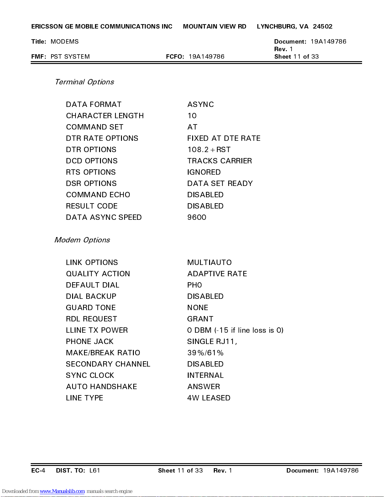
ERICSSON GE MOBILE COMMUNICATIONS INC MOUNTAIN VIEW RD LYNCHBURG, VA 24502
Title:
FMF:
MODEMS
PST SYSTEM
FCFO:
19A149786
Terminal Options
DATA FORMAT ASYNC
CHARACTER LENGTH 10
COMMAND SET AT
DTR RATE OPTIONS FIXED AT DTE RATE
DTR OPTIONS 108.2+RST
DCD OPTIONS TRACKS CARRIER
RTS OPTIONS IGNORED
DSR OPTIONS DATA SET READY
COMMAND ECHO DISABLED
RESULT CODE DISABLED
DATA ASYNC SPEED 9600
Document:
Rev.
1
Sheet 11 of
19A149786
33
Modem Options
LINK OPTIONS MULTIAUTO
QUALITY ACTION ADAPTIVE RATE
DEFAULT DIAL PH0
DIAL BACKUP DISABLED
GUARD TONE NONE
RDL REQUEST GRANT
LLINE TX POWER 0 DBM (-15 if line loss is 0)
PHONE JACK SINGLE RJ11,
MAKE/BREAK RATIO 39%/61%
SECONDARY CHANNEL DISABLED
SYNC CLOCK INTERNAL
AUTO HANDSHAKE ANSWER
LINE TYPE 4W LEASED
EC-
4
DIST. TO:
L61
Sheet 11 of 33 Rev.
1
Document:
19A149786
Page 37
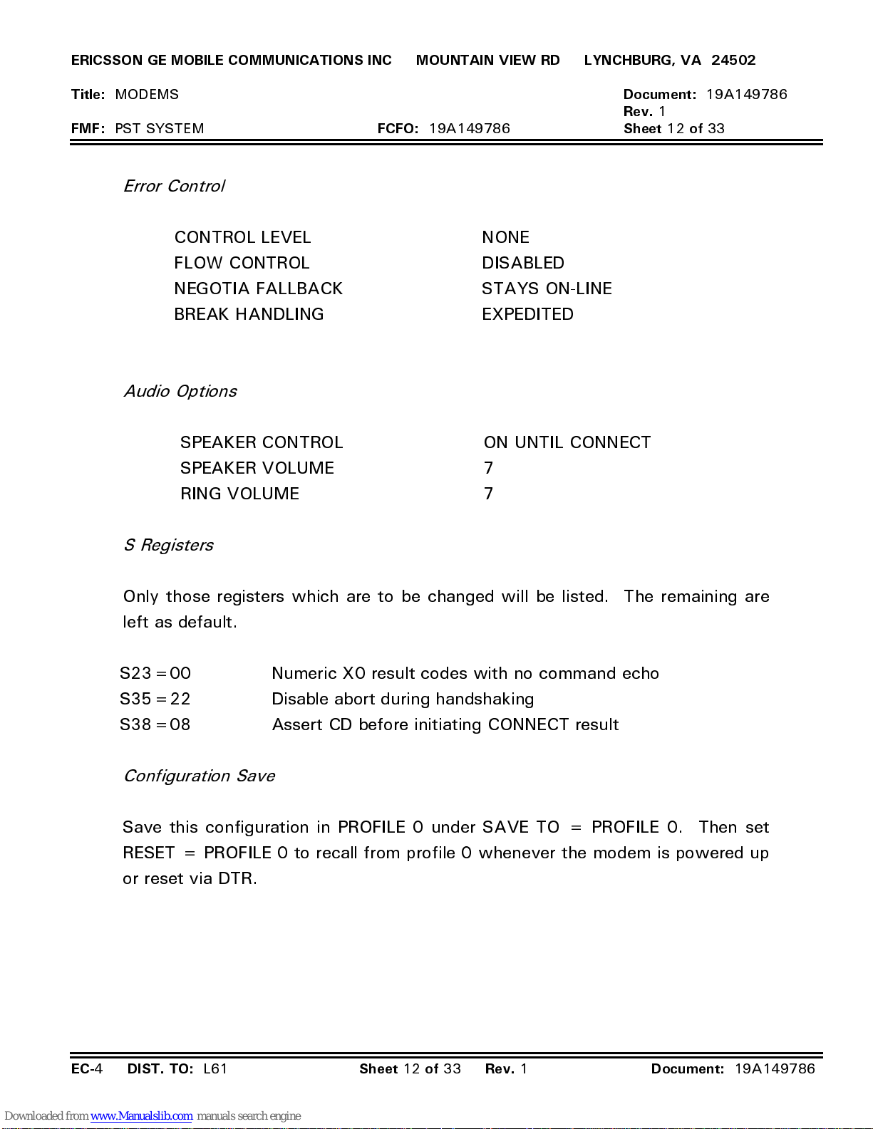
ERICSSON GE MOBILE COMMUNICATIONS INC MOUNTAIN VIEW RD LYNCHBURG, VA 24502
Title:
FMF:
MODEMS
PST SYSTEM
Error Control
CONTROL LEVEL NONE
FLOW CONTROL DISABLED
NEGOTIA FALLBACK STAYS ON-LINE
BREAK HANDLING EXPEDITED
Audio Options
SPEAKER CONTROL ON UNTIL CONNECT
SPEAKER VOLUME 7
RING VOLUME 7
FCFO:
19A149786
Document:
Rev.
1
Sheet 12 of
19A149786
33
S Registers
Only those registers which are to be changed will be listed. The remaining are
left as default.
S23=00 Numeric X0 result codes with no command echo
S35=22 Disable abort during handshaking
S38=08 Assert CD before initiating CONNECT result
Configuration Save
Save this configuration in PROFILE 0 under SAVE TO = PROFILE 0. Then set
RESET = PROFILE 0 to recall from profile 0 whenever the modem is powered up
or reset via DTR.
EC-
4
DIST. TO:
L61
Sheet 12 of 33 Rev.
1
Document:
19A149786
Page 38
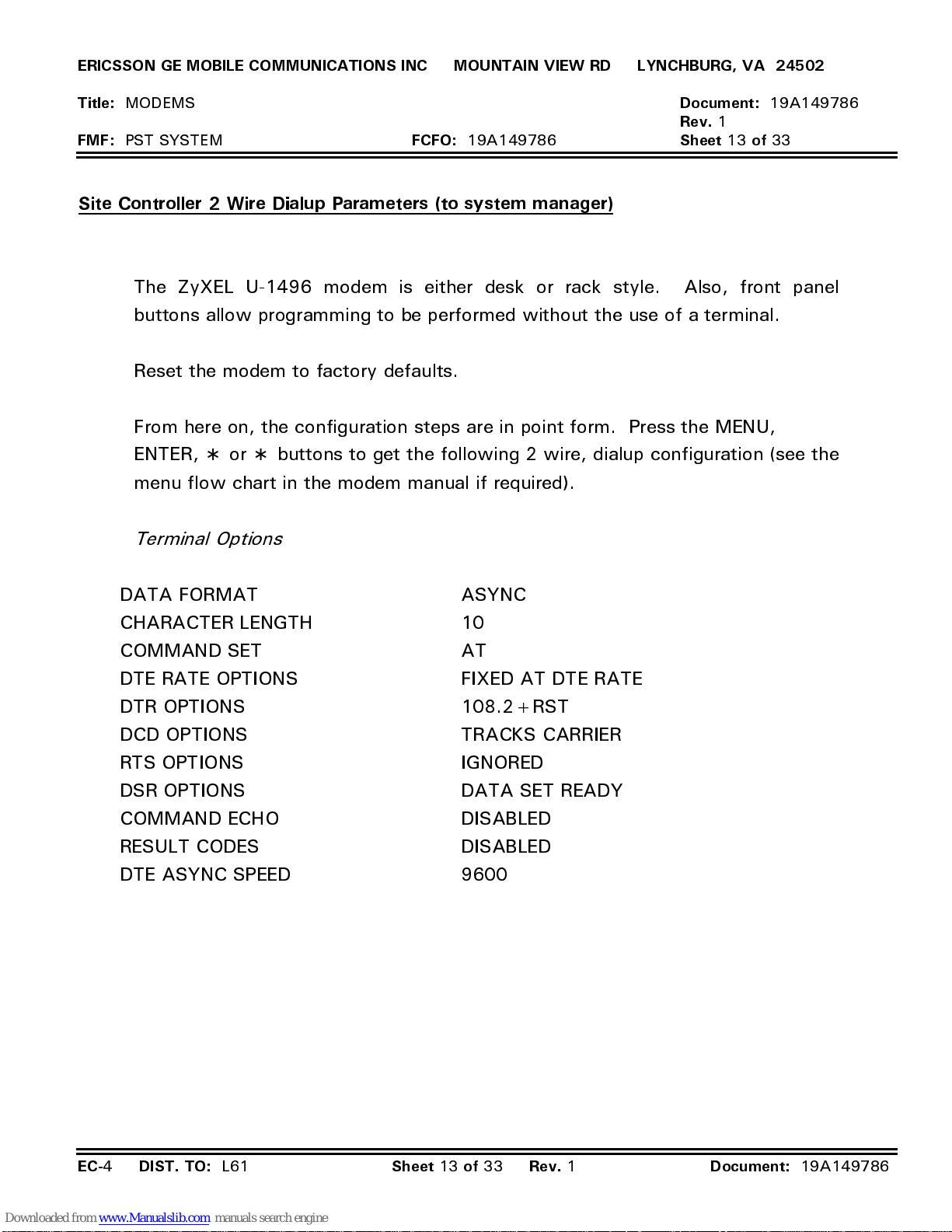
ERICSSON GE MOBILE COMMUNICATIONS INC MOUNTAIN VIEW RD LYNCHBURG, VA 24502
Title:
FMF:
MODEMS
PST SYSTEM
FCFO:
19A149786
Site Controller 2 Wire Dialup Parameters (to system manager)
The ZyXEL U-1496 modem is either desk or rack style. Also, front panel
buttons allow programming to be performed without the use of a terminal.
Reset the modem to factory defaults.
From here on, the configuration steps are in point form. Press the MENU,
ENTER, ∗ or ∗ buttons to get the following 2 wire, dialup configuration (see the
menu flow chart in the modem manual if required).
Terminal Options
Document:
Rev.
1
Sheet 13 of
19A149786
33
DATA FORMAT ASYNC
CHARACTER LENGTH 10
COMMAND SET AT
DTE RATE OPTIONS FIXED AT DTE RATE
DTR OPTIONS 108.2+RST
DCD OPTIONS TRACKS CARRIER
RTS OPTIONS IGNORED
DSR OPTIONS DATA SET READY
COMMAND ECHO DISABLED
RESULT CODES DISABLED
DTE ASYNC SPEED 9600
EC-
4
DIST. TO:
L61
Sheet 13 of 33 Rev.
1
Document:
19A149786
Page 39
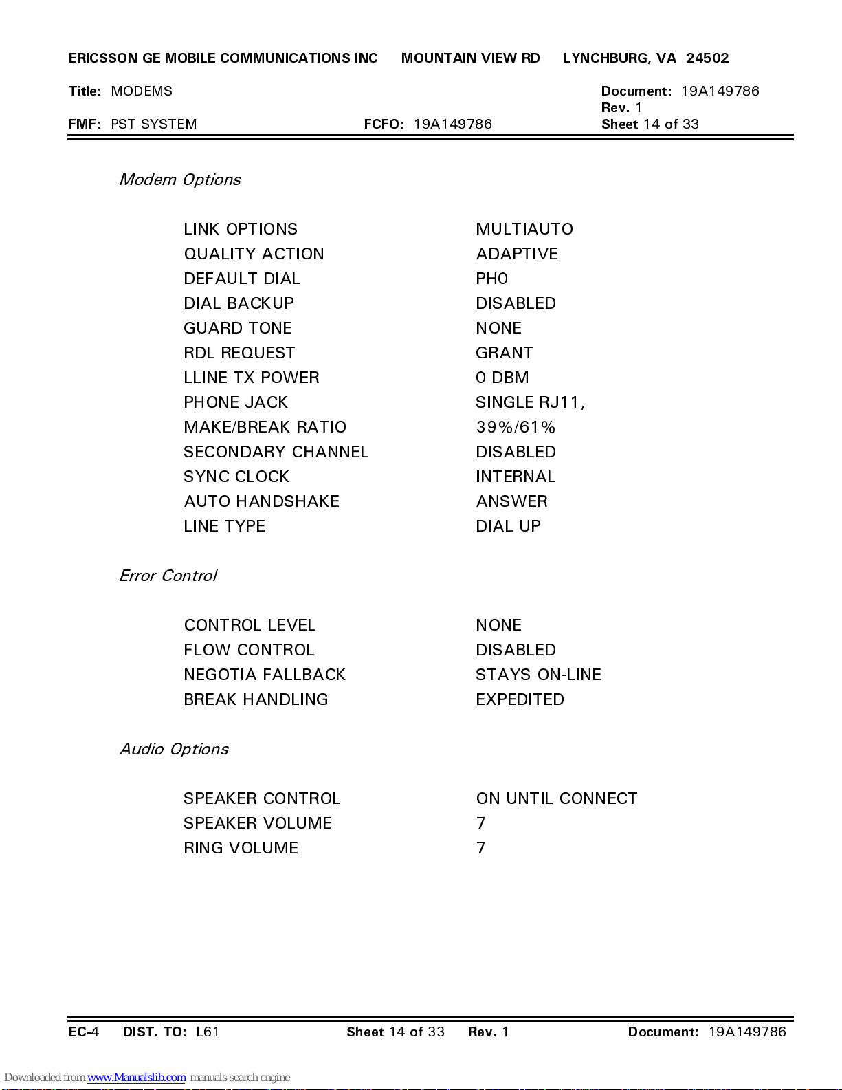
ERICSSON GE MOBILE COMMUNICATIONS INC MOUNTAIN VIEW RD LYNCHBURG, VA 24502
Title:
FMF:
MODEMS
PST SYSTEM
Modem Options
LINK OPTIONS MULTIAUTO
QUALITY ACTION ADAPTIVE
DEFAULT DIAL PH0
DIAL BACKUP DISABLED
GUARD TONE NONE
RDL REQUEST GRANT
LLINE TX POWER 0 DBM
PHONE JACK SINGLE RJ11,
MAKE/BREAK RATIO 39%/61%
SECONDARY CHANNEL DISABLED
SYNC CLOCK INTERNAL
FCFO:
19A149786
Document:
Rev.
1
Sheet 14 of
19A149786
33
AUTO HANDSHAKE ANSWER
LINE TYPE DIAL UP
Error Control
CONTROL LEVEL NONE
FLOW CONTROL DISABLED
NEGOTIA FALLBACK STAYS ON-LINE
BREAK HANDLING EXPEDITED
Audio Options
SPEAKER CONTROL ON UNTIL CONNECT
SPEAKER VOLUME 7
RING VOLUME 7
EC-
4
DIST. TO:
L61
Sheet 14 of 33 Rev.
1
Document:
19A149786
Page 40
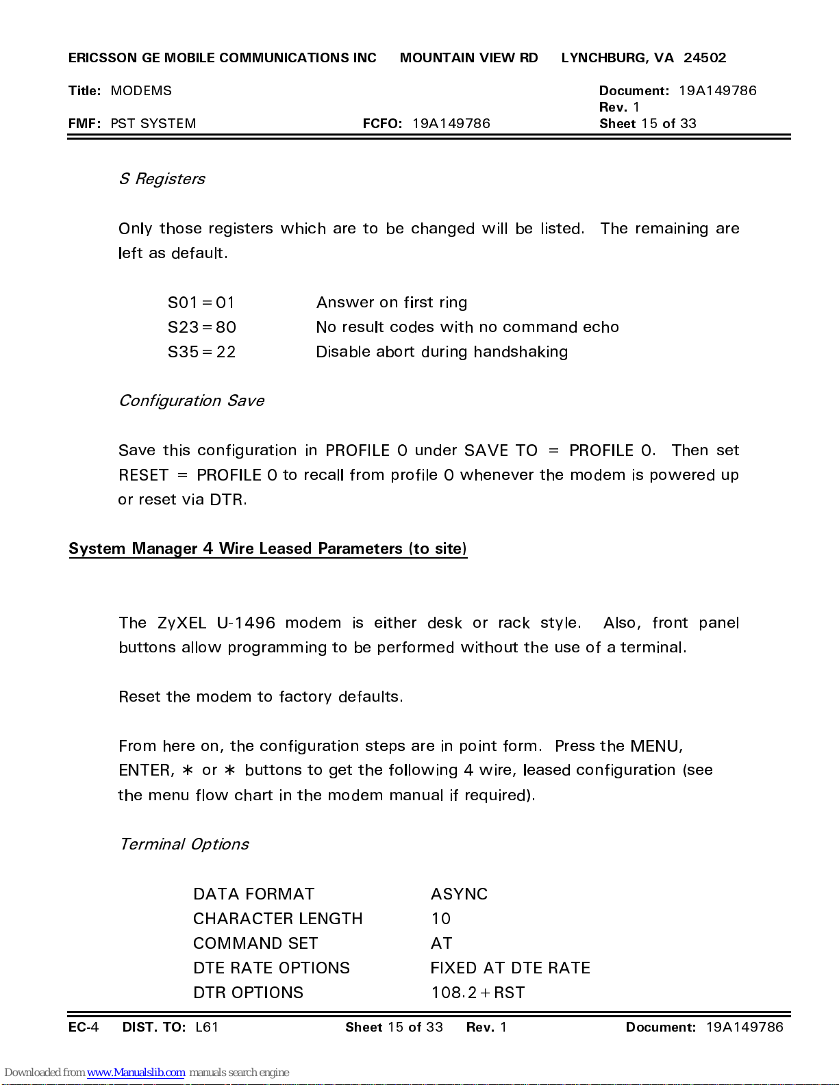
ERICSSON GE MOBILE COMMUNICATIONS INC MOUNTAIN VIEW RD LYNCHBURG, VA 24502
Title:
FMF:
MODEMS
PST SYSTEM
FCFO:
19A149786
Document:
Rev.
1
Sheet 15 of
19A149786
33
S Registers
Only those registers which are to be changed will be listed. The remaining are
left as default.
S01=01 Answer on first ring
S23=80 No result codes with no command echo
S35=22 Disable abort during handshaking
Configuration Save
Save this configuration in PROFILE 0 under SAVE TO = PROFILE 0. Then set
RESET = PROFILE 0 to recall from profile 0 whenever the modem is powered up
or reset via DTR.
System Manager 4 Wire Leased Parameters (to site)
The ZyXEL U-1496 modem is either desk or rack style. Also, front panel
buttons allow programming to be performed without the use of a terminal.
Reset the modem to factory defaults.
From here on, the configuration steps are in point form. Press the MENU,
ENTER, ∗ or ∗ buttons to get the following 4 wire, leased configuration (see
the menu flow chart in the modem manual if required).
Terminal Options
DATA FORMAT ASYNC
CHARACTER LENGTH 10
COMMAND SET AT
DTE RATE OPTIONS FIXED AT DTE RATE
DTR OPTIONS 108.2+RST
EC-
4
DIST. TO:
L61
Sheet 15 of 33 Rev.
1
Document:
19A149786
Page 41
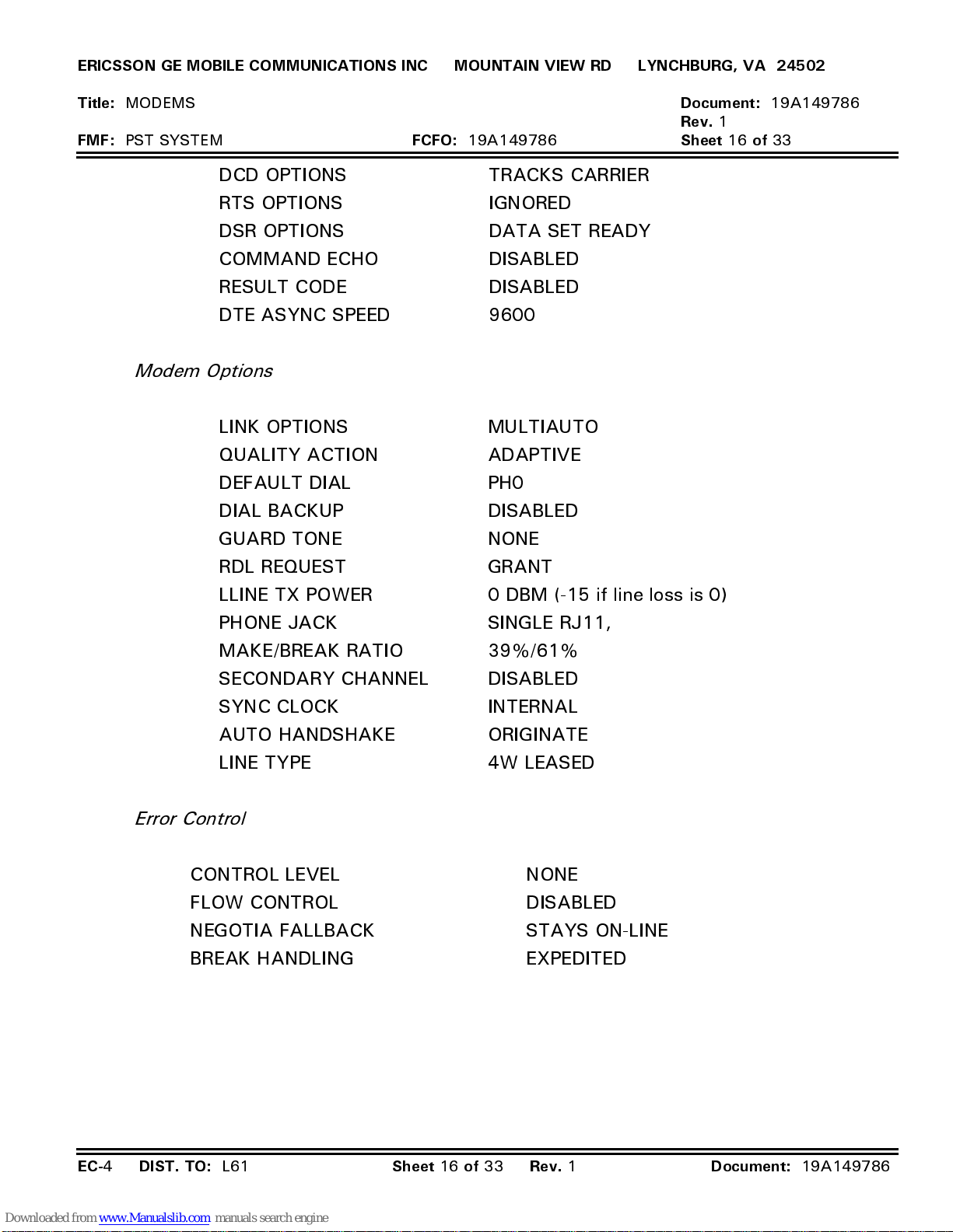
ERICSSON GE MOBILE COMMUNICATIONS INC MOUNTAIN VIEW RD LYNCHBURG, VA 24502
Title:
FMF:
MODEMS
PST SYSTEM
DCD OPTIONS TRACKS CARRIER
RTS OPTIONS IGNORED
DSR OPTIONS DATA SET READY
COMMAND ECHO DISABLED
RESULT CODE DISABLED
DTE ASYNC SPEED 9600
Modem Options
LINK OPTIONS MULTIAUTO
QUALITY ACTION ADAPTIVE
DEFAULT DIAL PH0
DIAL BACKUP DISABLED
GUARD TONE NONE
FCFO:
19A149786
Document:
Rev.
1
Sheet 16 of
19A149786
33
RDL REQUEST GRANT
LLINE TX POWER 0 DBM (-15 if line loss is 0)
PHONE JACK SINGLE RJ11,
MAKE/BREAK RATIO 39%/61%
SECONDARY CHANNEL DISABLED
SYNC CLOCK INTERNAL
AUTO HANDSHAKE ORIGINATE
LINE TYPE 4W LEASED
Error Control
CONTROL LEVEL NONE
FLOW CONTROL DISABLED
NEGOTIA FALLBACK STAYS ON-LINE
BREAK HANDLING EXPEDITED
EC-
4
DIST. TO:
L61
Sheet 16 of 33 Rev.
1
Document:
19A149786
Page 42
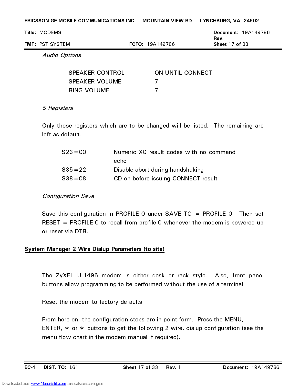
ERICSSON GE MOBILE COMMUNICATIONS INC MOUNTAIN VIEW RD LYNCHBURG, VA 24502
Title:
FMF:
MODEMS
PST SYSTEM
FCFO:
19A149786
Document:
Rev.
1
Sheet 17 of
19A149786
33
Audio Options
SPEAKER CONTROL ON UNTIL CONNECT
SPEAKER VOLUME 7
RING VOLUME 7
S Registers
Only those registers which are to be changed will be listed. The remaining are
left as default.
S23=00 Numeric X0 result codes with no command
echo
S35=22 Disable abort during handshaking
S38=08 CD on before issuing CONNECT result
Configuration Save
Save this configuration in PROFILE 0 under SAVE TO = PROFILE 0. Then set
RESET = PROFILE 0 to recall from profile 0 whenever the modem is powered up
or reset via DTR.
System Manager 2 Wire Dialup Parameters (to site)
The ZyXEL U-1496 modem is either desk or rack style. Also, front panel
buttons allow programming to be performed without the use of a terminal.
Reset the modem to factory defaults.
From here on, the configuration steps are in point form. Press the MENU,
ENTER, ∗ or ∗ buttons to get the following 2 wire, dialup configuration (see the
menu flow chart in the modem manual if required).
EC-
4
DIST. TO:
L61
Sheet 17 of 33 Rev.
1
Document:
19A149786
Page 43
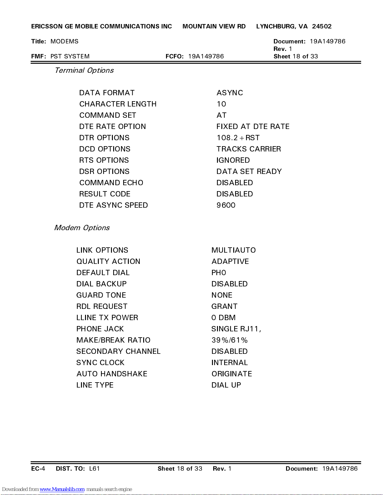
ERICSSON GE MOBILE COMMUNICATIONS INC MOUNTAIN VIEW RD LYNCHBURG, VA 24502
Title:
FMF:
MODEMS
PST SYSTEM
Terminal Options
DATA FORMAT ASYNC
CHARACTER LENGTH 10
COMMAND SET AT
DTE RATE OPTION FIXED AT DTE RATE
DTR OPTIONS 108.2+RST
DCD OPTIONS TRACKS CARRIER
RTS OPTIONS IGNORED
DSR OPTIONS DATA SET READY
COMMAND ECHO DISABLED
RESULT CODE DISABLED
DTE ASYNC SPEED 9600
FCFO:
19A149786
Document:
Rev.
1
Sheet 18 of
19A149786
33
Modem Options
LINK OPTIONS MULTIAUTO
QUALITY ACTION ADAPTIVE
DEFAULT DIAL PH0
DIAL BACKUP DISABLED
GUARD TONE NONE
RDL REQUEST GRANT
LLINE TX POWER 0 DBM
PHONE JACK SINGLE RJ11,
MAKE/BREAK RATIO 39%/61%
SECONDARY CHANNEL DISABLED
SYNC CLOCK INTERNAL
AUTO HANDSHAKE ORIGINATE
LINE TYPE DIAL UP
EC-
4
DIST. TO:
L61
Sheet 18 of 33 Rev.
1
Document:
19A149786
Page 44
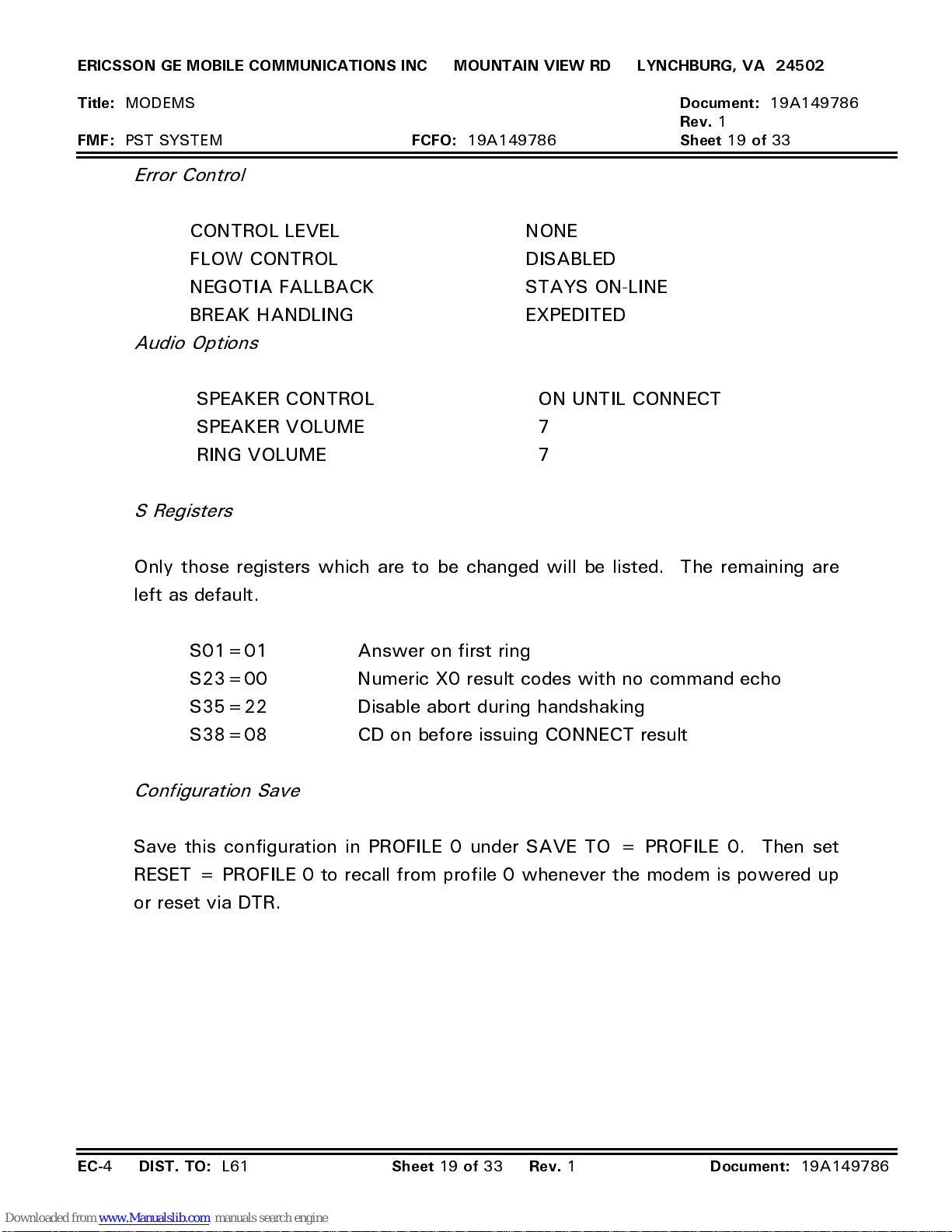
ERICSSON GE MOBILE COMMUNICATIONS INC MOUNTAIN VIEW RD LYNCHBURG, VA 24502
Title:
FMF:
MODEMS
PST SYSTEM
Error Control
CONTROL LEVEL NONE
FLOW CONTROL DISABLED
NEGOTIA FALLBACK STAYS ON-LINE
BREAK HANDLING EXPEDITED
Audio Options
SPEAKER CONTROL ON UNTIL CONNECT
SPEAKER VOLUME 7
RING VOLUME 7
S Registers
FCFO:
19A149786
Document:
Rev.
1
Sheet 19 of
19A149786
33
Only those registers which are to be changed will be listed. The remaining are
left as default.
S01=01 Answer on first ring
S23=00 Numeric X0 result codes with no command echo
S35=22 Disable abort during handshaking
S38=08 CD on before issuing CONNECT result
Configuration Save
Save this configuration in PROFILE 0 under SAVE TO = PROFILE 0. Then set
RESET = PROFILE 0 to recall from profile 0 whenever the modem is powered up
or reset via DTR.
EC-
4
DIST. TO:
L61
Sheet 19 of 33 Rev.
1
Document:
19A149786
Page 45
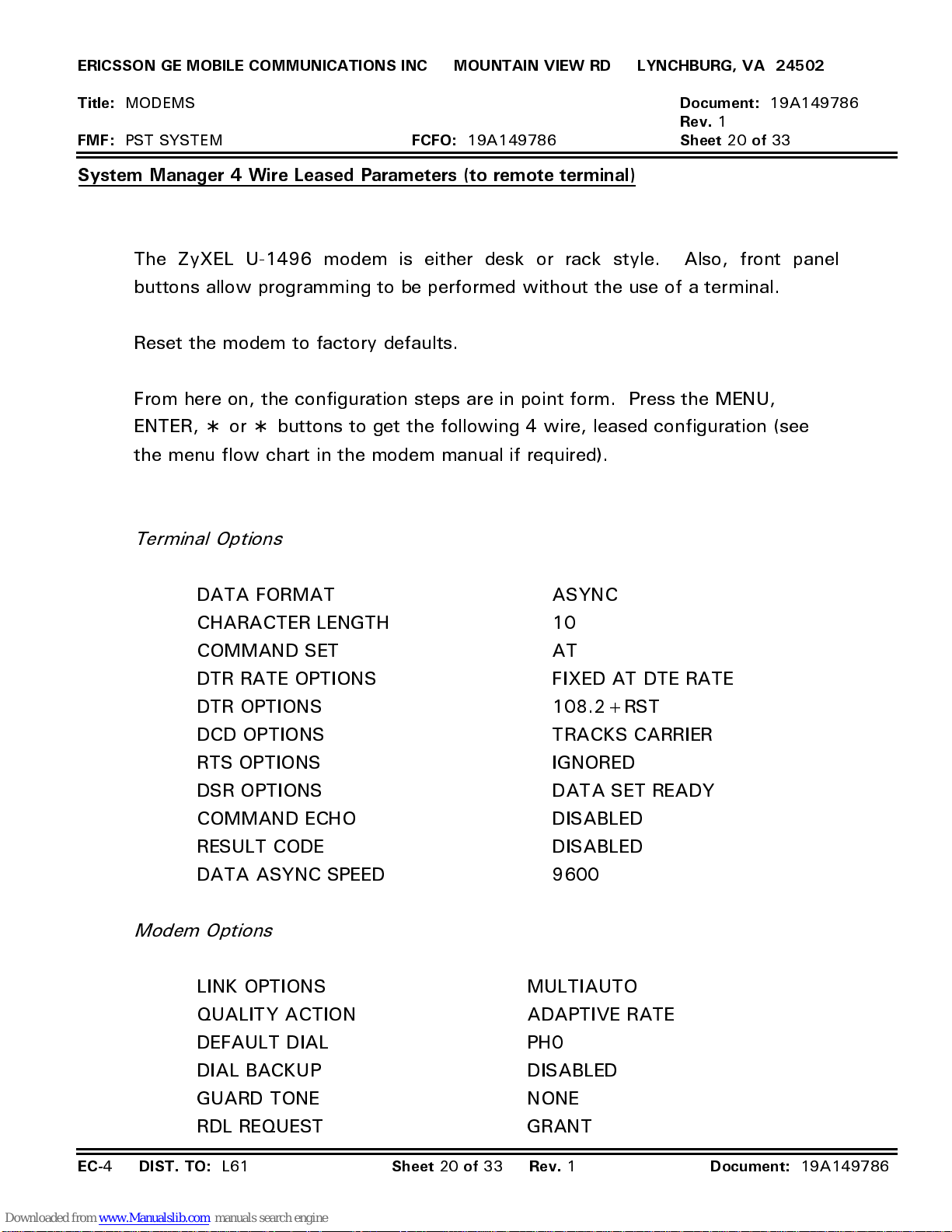
ERICSSON GE MOBILE COMMUNICATIONS INC MOUNTAIN VIEW RD LYNCHBURG, VA 24502
Title:
FMF:
MODEMS
PST SYSTEM
FCFO:
19A149786
System Manager 4 Wire Leased Parameters (to remote terminal)
The ZyXEL U-1496 modem is either desk or rack style. Also, front panel
buttons allow programming to be performed without the use of a terminal.
Reset the modem to factory defaults.
From here on, the configuration steps are in point form. Press the MENU,
ENTER, ∗ or ∗ buttons to get the following 4 wire, leased configuration (see
the menu flow chart in the modem manual if required).
Terminal Options
Document:
Rev.
1
Sheet 20 of
19A149786
33
DATA FORMAT ASYNC
CHARACTER LENGTH 10
COMMAND SET AT
DTR RATE OPTIONS FIXED AT DTE RATE
DTR OPTIONS 108.2+RST
DCD OPTIONS TRACKS CARRIER
RTS OPTIONS IGNORED
DSR OPTIONS DATA SET READY
COMMAND ECHO DISABLED
RESULT CODE DISABLED
DATA ASYNC SPEED 9600
Modem Options
LINK OPTIONS MULTIAUTO
QUALITY ACTION ADAPTIVE RATE
DEFAULT DIAL PH0
DIAL BACKUP DISABLED
GUARD TONE NONE
RDL REQUEST GRANT
EC-
4
DIST. TO:
L61
Sheet 20 of 33 Rev.
1
Document:
19A149786
Page 46
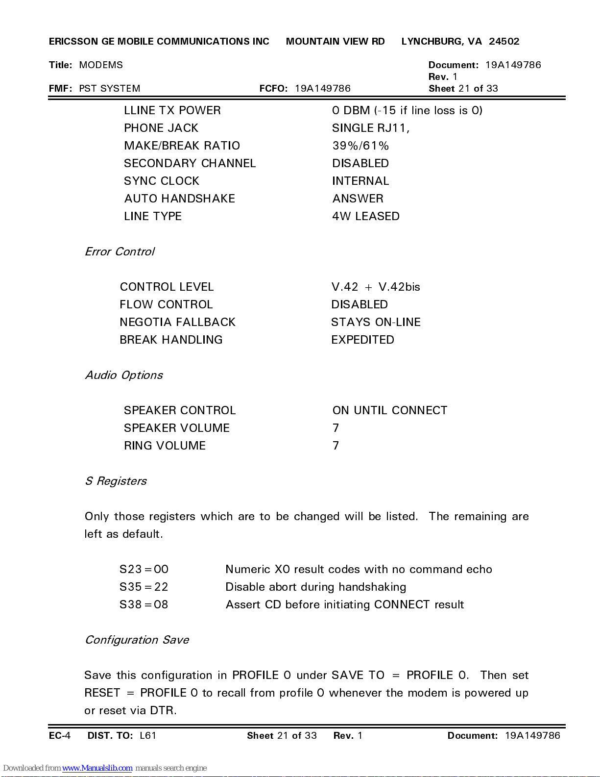
ERICSSON GE MOBILE COMMUNICATIONS INC MOUNTAIN VIEW RD LYNCHBURG, VA 24502
Title:
FMF:
MODEMS
PST SYSTEM
LLINE TX POWER 0 DBM (-15 if line loss is 0)
PHONE JACK SINGLE RJ11,
MAKE/BREAK RATIO 39%/61%
SECONDARY CHANNEL DISABLED
SYNC CLOCK INTERNAL
AUTO HANDSHAKE ANSWER
LINE TYPE 4W LEASED
Error Control
CONTROL LEVEL V.42 + V.42bis
FLOW CONTROL DISABLED
NEGOTIA FALLBACK STAYS ON-LINE
BREAK HANDLING EXPEDITED
FCFO:
19A149786
Document:
Rev.
1
Sheet 21 of
19A149786
33
Audio Options
SPEAKER CONTROL ON UNTIL CONNECT
SPEAKER VOLUME 7
RING VOLUME 7
S Registers
Only those registers which are to be changed will be listed. The remaining are
left as default.
S23=00 Numeric X0 result codes with no command echo
S35=22 Disable abort during handshaking
S38=08 Assert CD before initiating CONNECT result
Configuration Save
Save this configuration in PROFILE 0 under SAVE TO = PROFILE 0. Then set
RESET = PROFILE 0 to recall from profile 0 whenever the modem is powered up
or reset via DTR.
EC-
4
DIST. TO:
L61
Sheet 21 of 33 Rev.
1
Document:
19A149786
Page 47
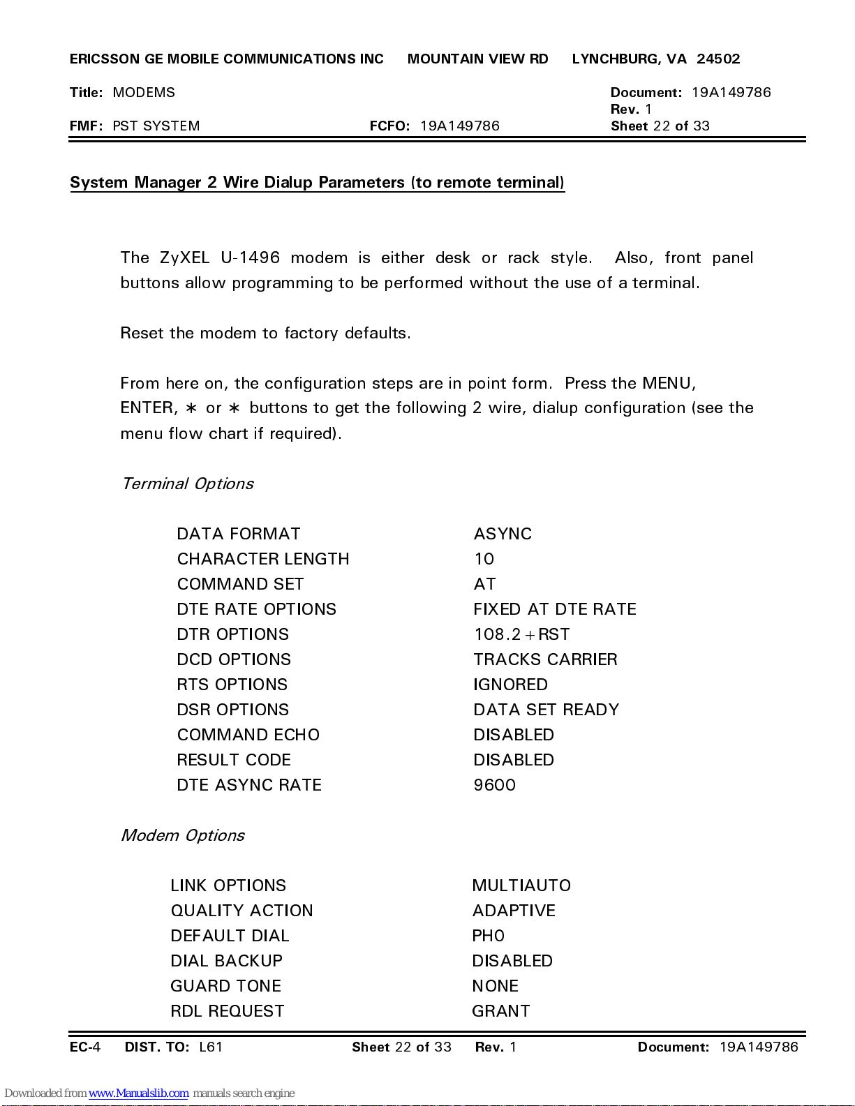
ERICSSON GE MOBILE COMMUNICATIONS INC MOUNTAIN VIEW RD LYNCHBURG, VA 24502
Title:
FMF:
MODEMS
PST SYSTEM
FCFO:
19A149786
System Manager 2 Wire Dialup Parameters (to remote terminal)
The ZyXEL U-1496 modem is either desk or rack style. Also, front panel
buttons allow programming to be performed without the use of a terminal.
Reset the modem to factory defaults.
From here on, the configuration steps are in point form. Press the MENU,
ENTER, ∗ or ∗ buttons to get the following 2 wire, dialup configuration (see the
menu flow chart if required).
Terminal Options
Document:
Rev.
1
Sheet 22 of
19A149786
33
DATA FORMAT ASYNC
CHARACTER LENGTH 10
COMMAND SET AT
DTE RATE OPTIONS FIXED AT DTE RATE
DTR OPTIONS 108.2+RST
DCD OPTIONS TRACKS CARRIER
RTS OPTIONS IGNORED
DSR OPTIONS DATA SET READY
COMMAND ECHO DISABLED
RESULT CODE DISABLED
DTE ASYNC RATE 9600
Modem Options
LINK OPTIONS MULTIAUTO
QUALITY ACTION ADAPTIVE
DEFAULT DIAL PH0
DIAL BACKUP DISABLED
GUARD TONE NONE
RDL REQUEST GRANT
EC-
4
DIST. TO:
L61
Sheet 22 of 33 Rev.
1
Document:
19A149786
Page 48
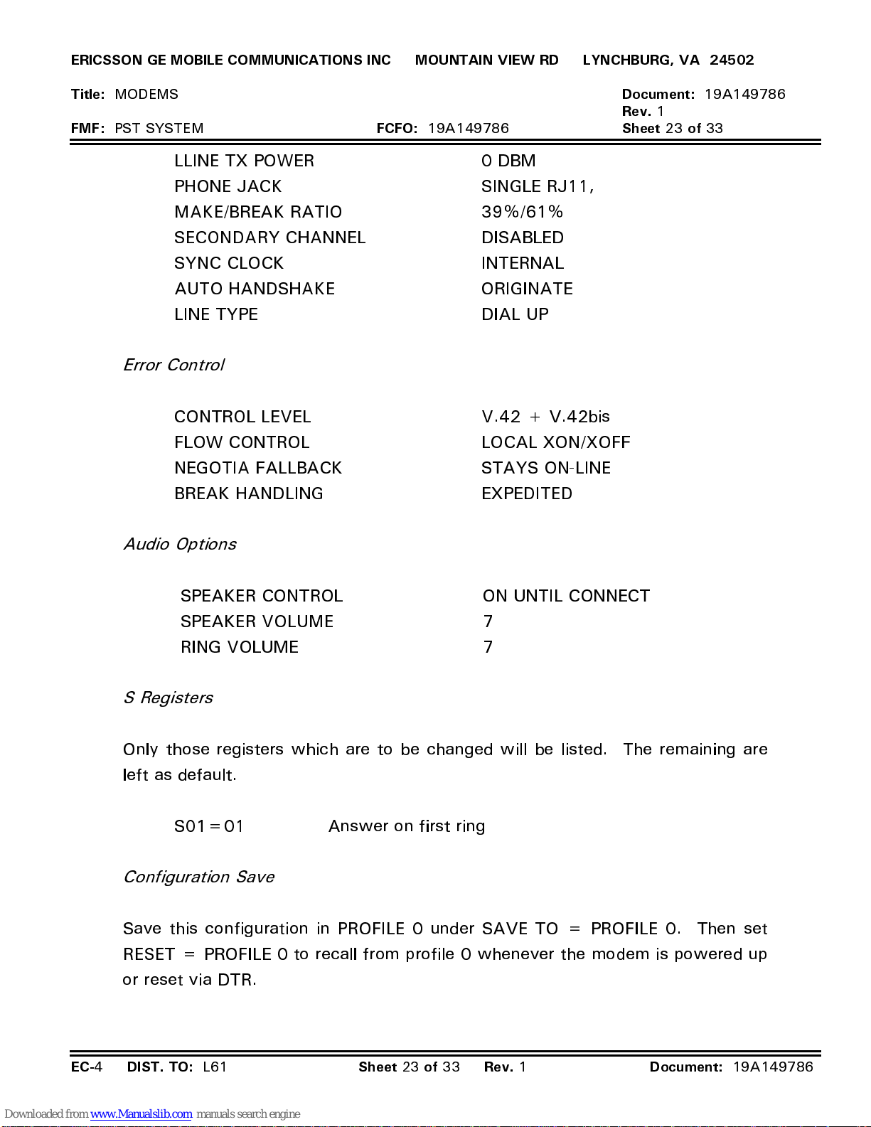
ERICSSON GE MOBILE COMMUNICATIONS INC MOUNTAIN VIEW RD LYNCHBURG, VA 24502
Title:
FMF:
MODEMS
PST SYSTEM
LLINE TX POWER 0 DBM
PHONE JACK SINGLE RJ11,
MAKE/BREAK RATIO 39%/61%
SECONDARY CHANNEL DISABLED
SYNC CLOCK INTERNAL
AUTO HANDSHAKE ORIGINATE
LINE TYPE DIAL UP
Error Control
CONTROL LEVEL V.42 + V.42bis
FLOW CONTROL LOCAL XON/XOFF
NEGOTIA FALLBACK STAYS ON-LINE
BREAK HANDLING EXPEDITED
FCFO:
19A149786
Document:
Rev.
1
Sheet 23 of
19A149786
33
Audio Options
SPEAKER CONTROL ON UNTIL CONNECT
SPEAKER VOLUME 7
RING VOLUME 7
S Registers
Only those registers which are to be changed will be listed. The remaining are
left as default.
S01=01 Answer on first ring
Configuration Save
Save this configuration in PROFILE 0 under SAVE TO = PROFILE 0. Then set
RESET = PROFILE 0 to recall from profile 0 whenever the modem is powered up
or reset via DTR.
EC-
4
DIST. TO:
L61
Sheet 23 of 33 Rev.
1
Document:
19A149786
Page 49
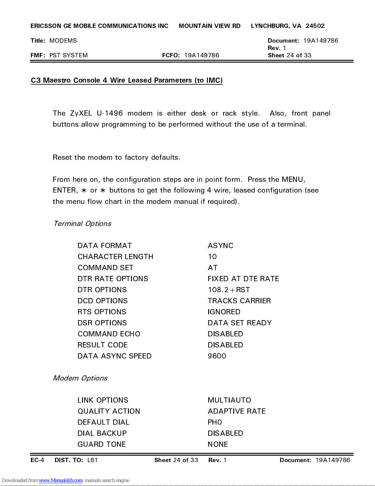
ERICSSON GE MOBILE COMMUNICATIONS INC MOUNTAIN VIEW RD LYNCHBURG, VA 24502
Title:
FMF:
MODEMS
PST SYSTEM
FCFO:
19A149786
C3 Maestro Console 4 Wire Leased Parameters (to IMC)
The ZyXEL U-1496 modem is either desk or rack style. Also, front panel
buttons allow programming to be performed without the use of a terminal.
Reset the modem to factory defaults.
From here on, the configuration steps are in point form. Press the MENU,
ENTER, ∗ or ∗ buttons to get the following 4 wire, leased configuration (see
the menu flow chart in the modem manual if required).
Document:
Rev.
1
Sheet 24 of
19A149786
33
Terminal Options
DATA FORMAT ASYNC
CHARACTER LENGTH 10
COMMAND SET AT
DTR RATE OPTIONS FIXED AT DTE RATE
DTR OPTIONS 108.2+RST
DCD OPTIONS TRACKS CARRIER
RTS OPTIONS IGNORED
DSR OPTIONS DATA SET READY
COMMAND ECHO DISABLED
RESULT CODE DISABLED
DATA ASYNC SPEED 9600
Modem Options
LINK OPTIONS MULTIAUTO
QUALITY ACTION ADAPTIVE RATE
DEFAULT DIAL PH0
DIAL BACKUP DISABLED
GUARD TONE NONE
EC-
4
DIST. TO:
L61
Sheet 24 of 33 Rev.
1
Document:
19A149786
Page 50
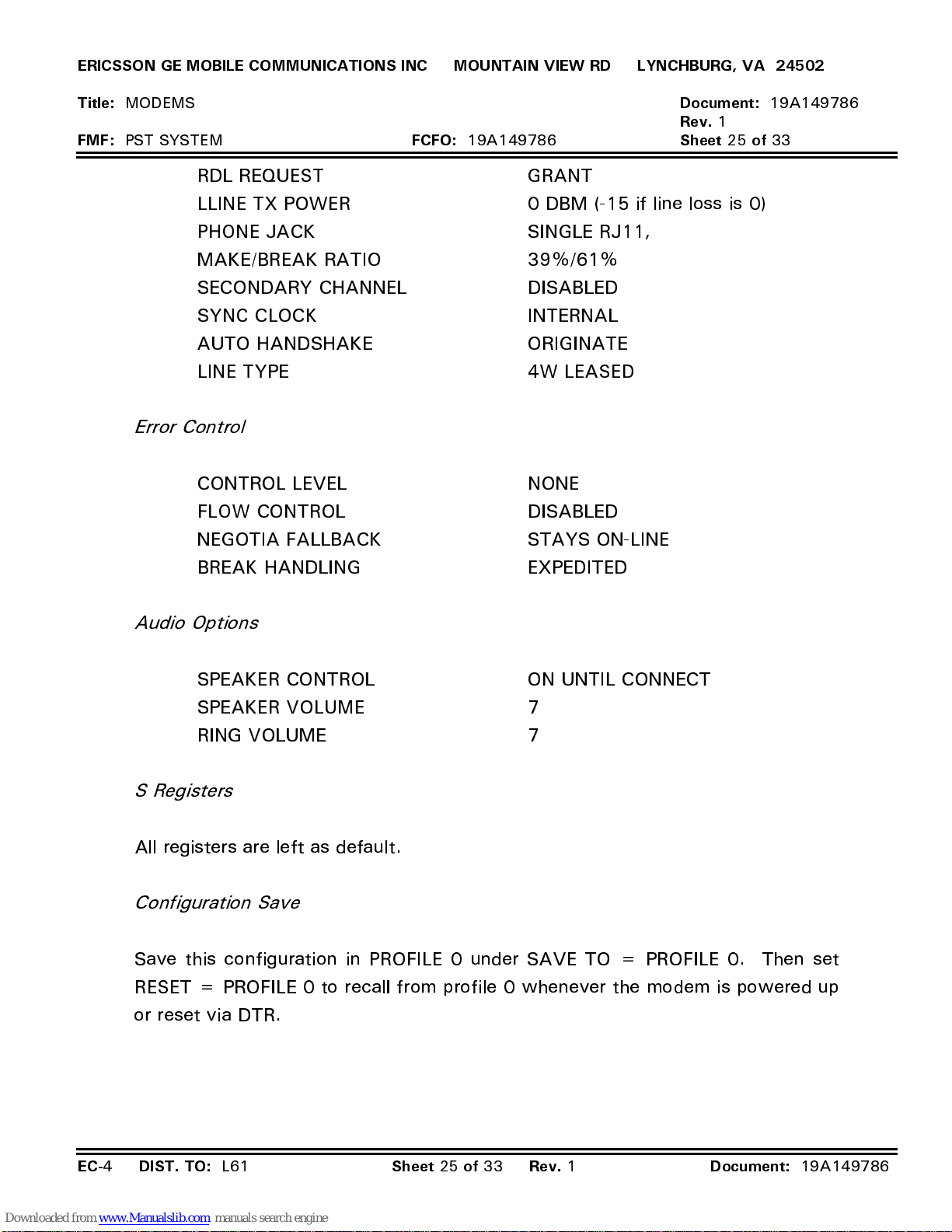
ERICSSON GE MOBILE COMMUNICATIONS INC MOUNTAIN VIEW RD LYNCHBURG, VA 24502
Title:
FMF:
MODEMS
PST SYSTEM
RDL REQUEST GRANT
LLINE TX POWER 0 DBM (-15 if line loss is 0)
PHONE JACK SINGLE RJ11,
MAKE/BREAK RATIO 39%/61%
SECONDARY CHANNEL DISABLED
SYNC CLOCK INTERNAL
AUTO HANDSHAKE ORIGINATE
LINE TYPE 4W LEASED
Error Control
CONTROL LEVEL NONE
FLOW CONTROL DISABLED
NEGOTIA FALLBACK STAYS ON-LINE
FCFO:
19A149786
Document:
Rev.
1
Sheet 25 of
19A149786
33
BREAK HANDLING EXPEDITED
Audio Options
SPEAKER CONTROL ON UNTIL CONNECT
SPEAKER VOLUME 7
RING VOLUME 7
S Registers
All registers are left as default.
Configuration Save
Save this configuration in PROFILE 0 under SAVE TO = PROFILE 0. Then set
RESET = PROFILE 0 to recall from profile 0 whenever the modem is powered up
or reset via DTR.
EC-
4
DIST. TO:
L61
Sheet 25 of 33 Rev.
1
Document:
19A149786
Page 51
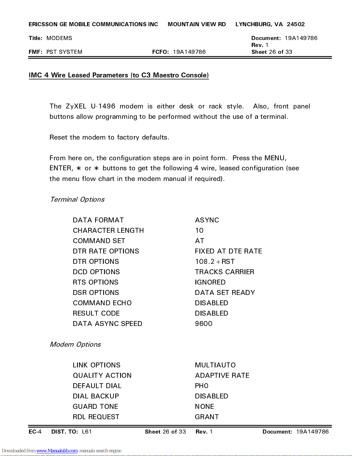
ERICSSON GE MOBILE COMMUNICATIONS INC MOUNTAIN VIEW RD LYNCHBURG, VA 24502
Title:
FMF:
MODEMS
PST SYSTEM
FCFO:
19A149786
IMC 4 Wire Leased Parameters (to C3 Maestro Console)
The ZyXEL U-1496 modem is either desk or rack style. Also, front panel
buttons allow programming to be performed without the use of a terminal.
Reset the modem to factory defaults.
From here on, the configuration steps are in point form. Press the MENU,
ENTER, ∗ or ∗ buttons to get the following 4 wire, leased configuration (see
the menu flow chart in the modem manual if required).
Terminal Options
Document:
Rev.
1
Sheet 26 of
19A149786
33
DATA FORMAT ASYNC
CHARACTER LENGTH 10
COMMAND SET AT
DTR RATE OPTIONS FIXED AT DTE RATE
DTR OPTIONS 108.2+RST
DCD OPTIONS TRACKS CARRIER
RTS OPTIONS IGNORED
DSR OPTIONS DATA SET READY
COMMAND ECHO DISABLED
RESULT CODE DISABLED
DATA ASYNC SPEED 9600
Modem Options
LINK OPTIONS MULTIAUTO
QUALITY ACTION ADAPTIVE RATE
DEFAULT DIAL PH0
DIAL BACKUP DISABLED
GUARD TONE NONE
RDL REQUEST GRANT
EC-
4
DIST. TO:
L61
Sheet 26 of 33 Rev.
1
Document:
19A149786
Page 52
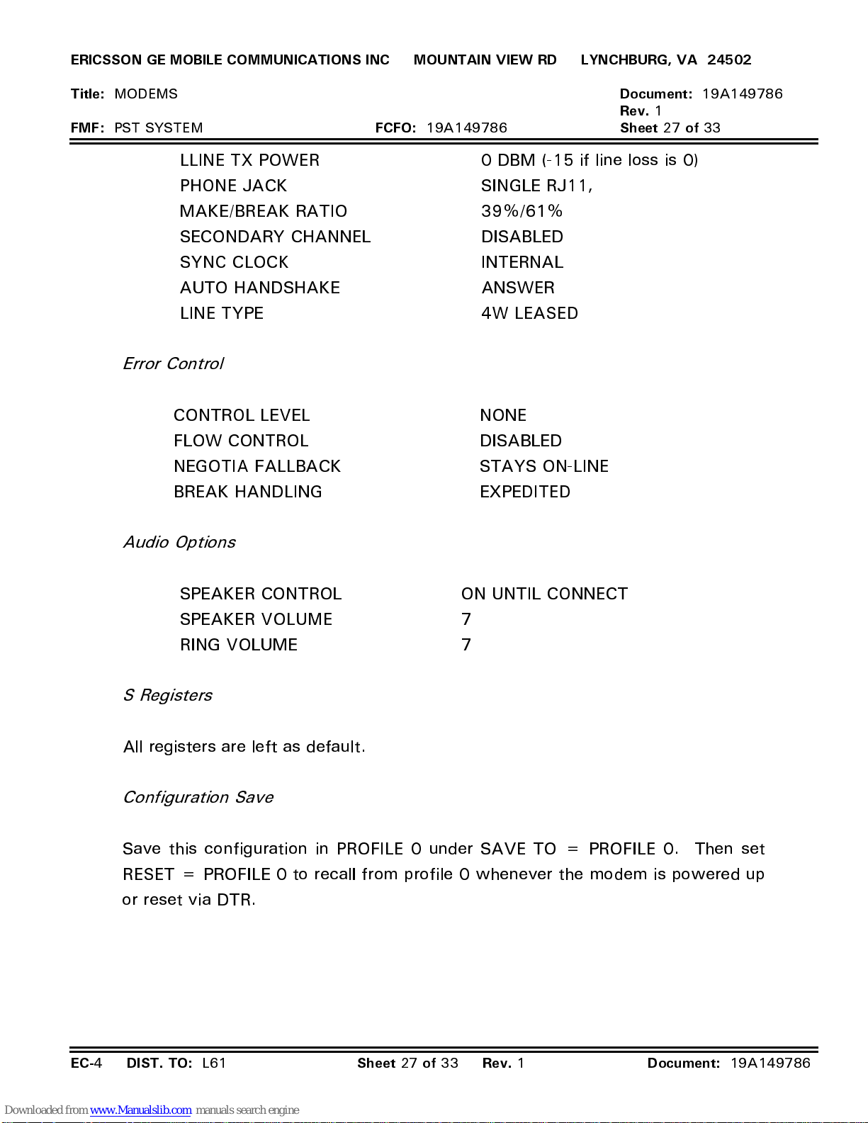
ERICSSON GE MOBILE COMMUNICATIONS INC MOUNTAIN VIEW RD LYNCHBURG, VA 24502
Title:
FMF:
MODEMS
PST SYSTEM
LLINE TX POWER 0 DBM (-15 if line loss is 0)
PHONE JACK SINGLE RJ11,
MAKE/BREAK RATIO 39%/61%
SECONDARY CHANNEL DISABLED
SYNC CLOCK INTERNAL
AUTO HANDSHAKE ANSWER
LINE TYPE 4W LEASED
Error Control
CONTROL LEVEL NONE
FLOW CONTROL DISABLED
NEGOTIA FALLBACK STAYS ON-LINE
BREAK HANDLING EXPEDITED
FCFO:
19A149786
Document:
Rev.
1
Sheet 27 of
19A149786
33
Audio Options
SPEAKER CONTROL ON UNTIL CONNECT
SPEAKER VOLUME 7
RING VOLUME 7
S Registers
All registers are left as default.
Configuration Save
Save this configuration in PROFILE 0 under SAVE TO = PROFILE 0. Then set
RESET = PROFILE 0 to recall from profile 0 whenever the modem is powered up
or reset via DTR.
EC-
4
DIST. TO:
L61
Sheet 27 of 33 Rev.
1
Document:
19A149786
Page 53
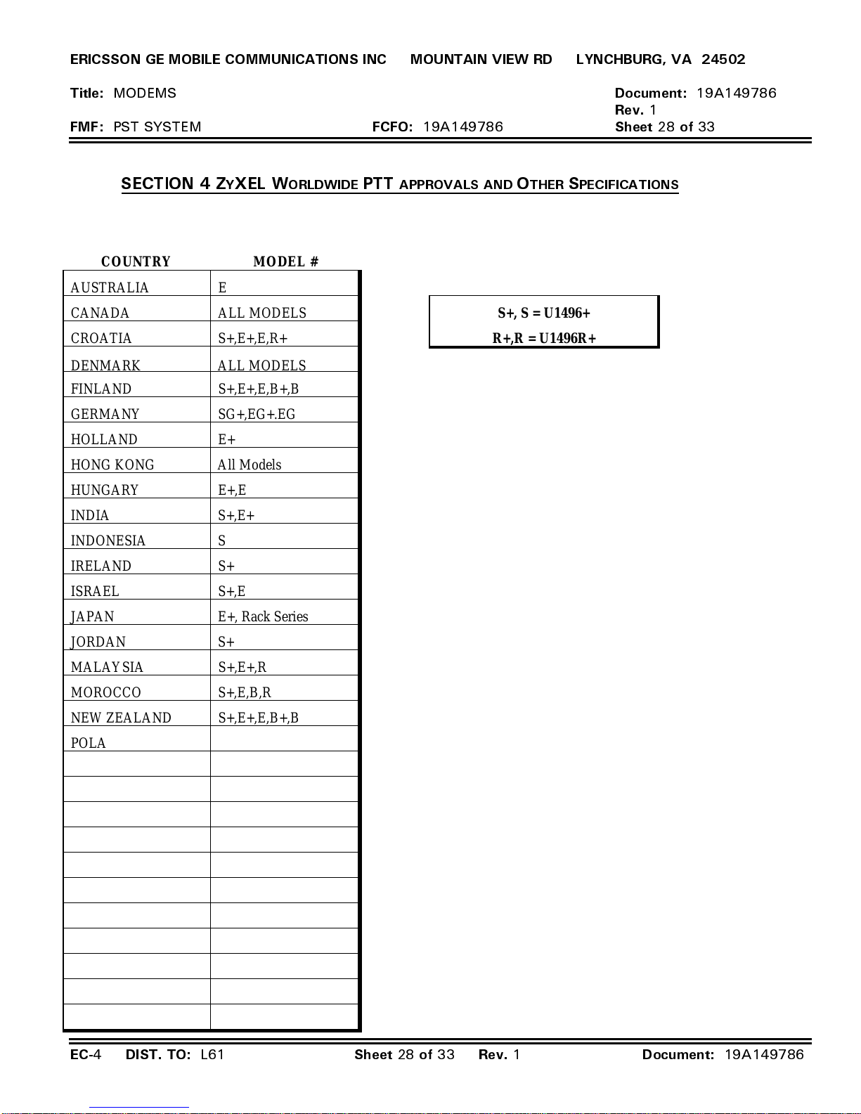
ERICSSON GE MOBILE COMMUNICATIONS INC MOUNTAIN VIEW RD LYNCHBURG, VA 24502
Title:
FMF:
AUSTRALIA E
CANADA ALL MODELS
CROATIA S+,E+,E,R+
DENMARK ALL MODELS
FINLAND S+,E+,E,B+,B
GERMANY SG+,EG+.EG
HOLLAND E+
HONG KONG All Models
HUNGARY E+,E
MODEMS
PST SYSTEM
SECTION 4 ZYXEL W
COUNTRY MODEL #
ORLDWIDE
FCFO:
PTT
19A149786
APPROVALS AND OTHER SPECIFICATIONS
S+, S = U1496+
R+,R = U1496R+
Document:
Rev.
1
Sheet 28 of
19A149786
33
INDIA S+,E+
INDONESIA S
IRELAND S+
ISRAEL S+,E
JAPAN E+, Rack Series
JORDAN S+
MALAYSIA S+,E+,R
MOROCCO S+,E,B,R
NEW ZEALAND S+,E+,E,B+,B
POLAND S+,E
RUSSIA S+,E+,E
SAUDI ARABIA S+
SINGAPORE All Models
SLOVAK All Models
SOUTH AFRICA S+,E+,E,R+,R
SWEDEN S+,E+,E,R+
SWITZERLAND All Models
THAILAND S+
TURKEY S+,E,B
UNITED STATES All Models
YUGOSLAVIA S+,E+,E
EC-
4
DIST. TO:
L61
Sheet 28 of 33 Rev.
1
Document:
19A149786
Page 54
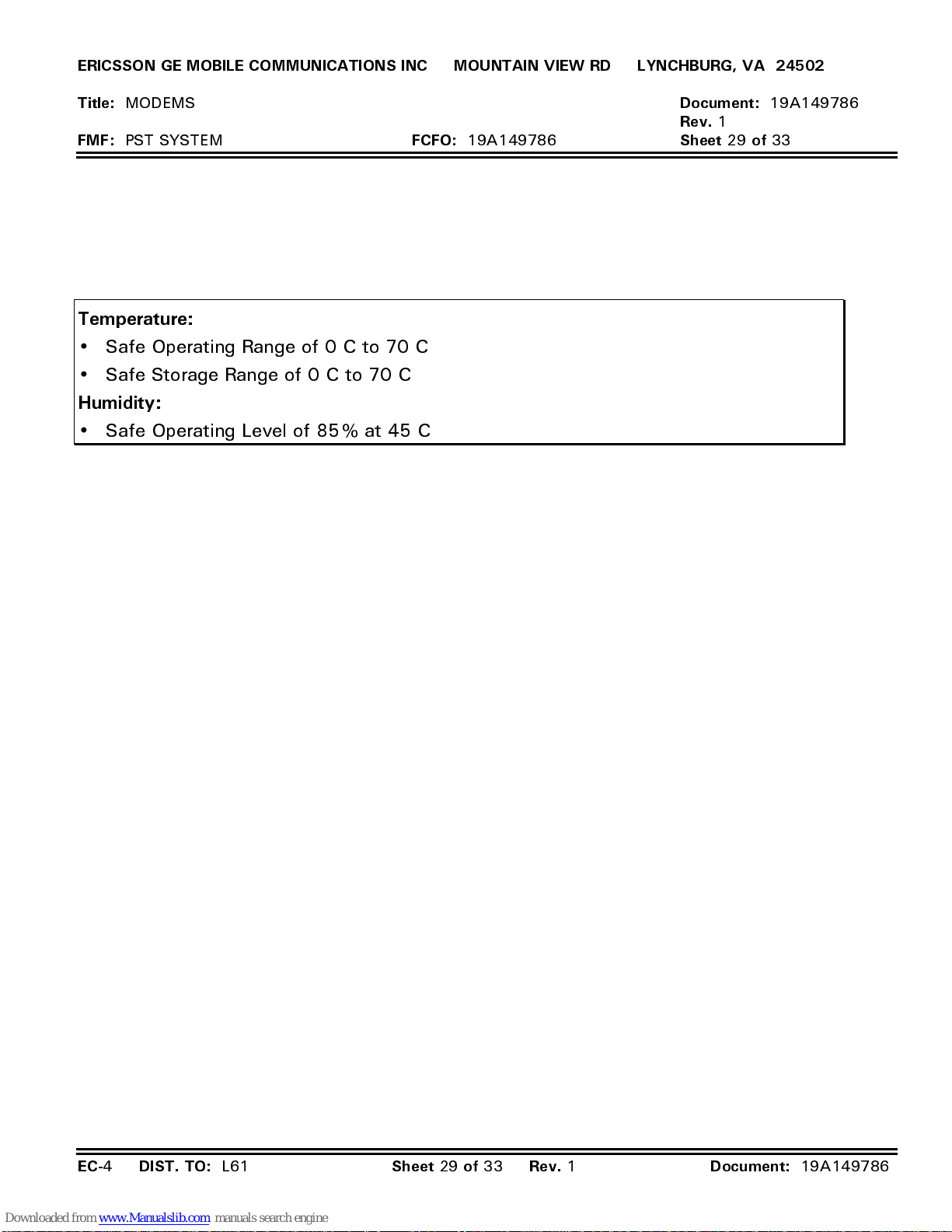
ERICSSON GE MOBILE COMMUNICATIONS INC MOUNTAIN VIEW RD LYNCHBURG, VA 24502
Title:
FMF:
MODEMS
PST SYSTEM
Temperature:
•
Safe Operating Range of 0 C to 70 C
•
Safe Storage Range of 0 C to 70 C
Humidity:
•
Safe Operating Level of 85% at 45 C
FCFO:
19A149786
Document:
Rev.
1
Sheet 29 of
19A149786
33
EC-
4
DIST. TO:
L61
Sheet 29 of 33 Rev.
1
Document:
19A149786
Page 55
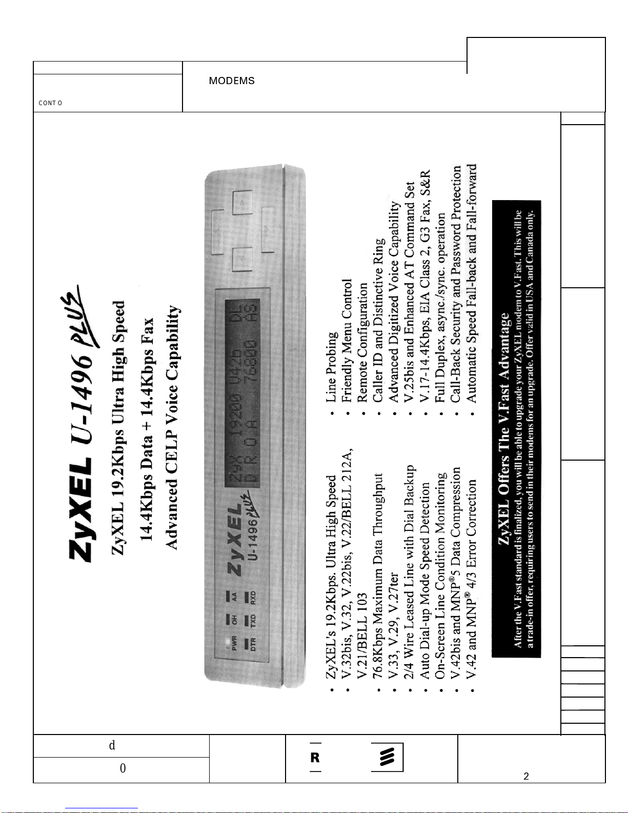
19A149786
REV NO. TITLE
CONT ON SHEET SH NO.
FIRST MADE FOR
MODEMS
PST SYSTEM
CONT ON SHEET
A2
F. C. F. O. 19A149786
REVISIONS
SH NO.
A1
MADE BY
E. Gaddy 19 Dec. 1994
ISSUED
E. G. 20 Dec. 1994
APPROVALS
Rene Gomez
20 Dec. 94
ERICSSONZM
19A149786
CONT ON SHEET
L61
PRINTS TO
SH NO.
A
2
A1
Page 56
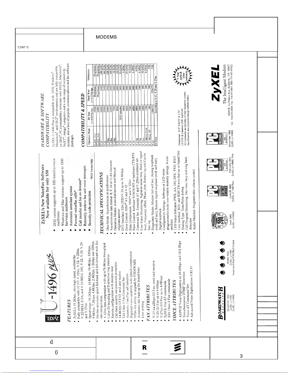
19A149786
REV NO. TITLE
CONT ON SHEET SH NO.
FIRST MADE FOR
MODEMS
PST SYSTEM
CONT ON SHEET
A3
F. C. F. O. 19A149786
REVISIONS
SH NO.
A2
MADE BY
E. Gaddy 19 Dec. 1994
ISSUED
E. G. 20 Dec. 1994
APPROVALS
Rene Gomez
20 Dec. 94
ERICSSONZM
19A149786
CONT ON SHEET
L61
PRINTS TO
SH NO.
A
3
A2
Page 57
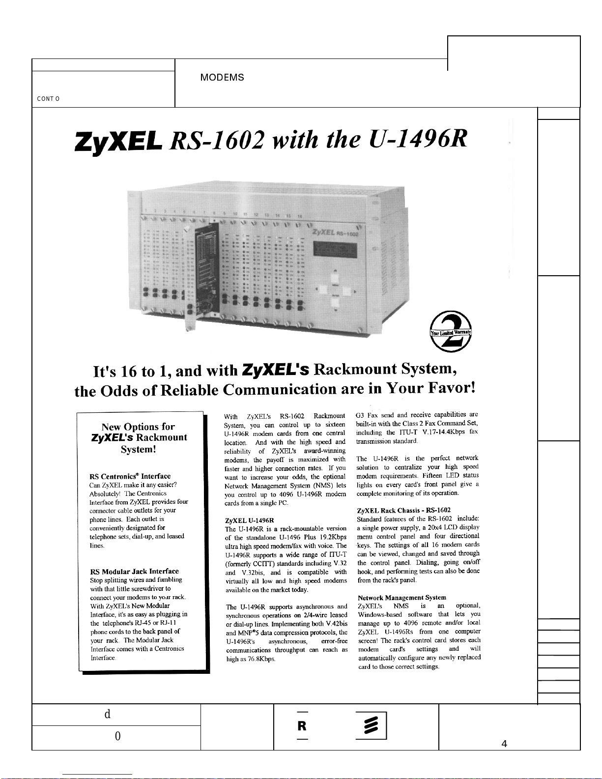
19A149786
REV NO. TITLE
CONT ON SHEET SH NO.
FIRST MADE FOR
MODEMS
PST SYSTEM
CONT ON SHEET
A4
F. C. F. O. 19A149786
REVISIONS
SH NO.
A3
MADE BY
E. Gaddy 19 Dec. 1994
ISSUED
E. G. 20 Dec. 1994
APPROVALS
Rene Gomez
20 Dec. 94
ERICSSONZM
19A149786
CONT ON SHEET
L61
PRINTS TO
SH NO.
A
4
A3
Page 58
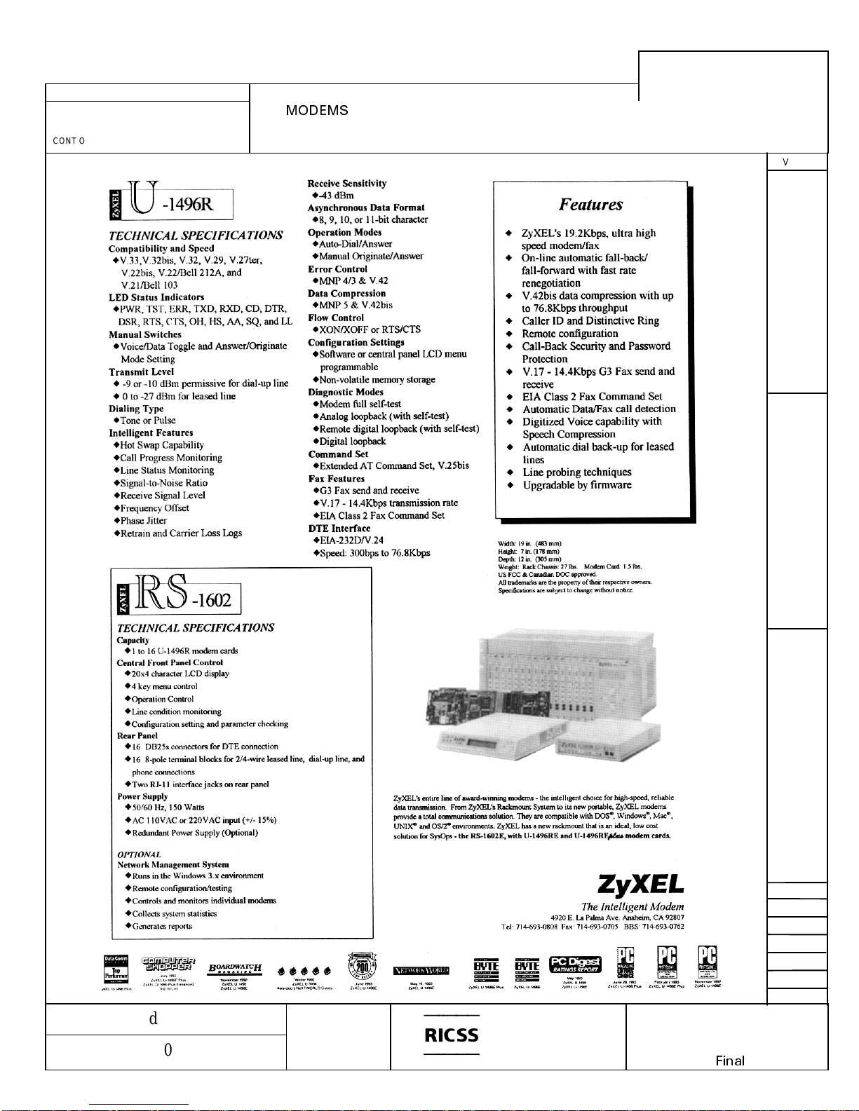
19A149786
REV NO. TITLE
CONT ON SHEET SH NO.
FIRST MADE FOR
MODEMS
PST SYSTEM
CONT ON SHEET
AFinal
F. C. F. O. 19A149786
REVISIONS
SH NO.
A4
MADE BY
E. Gaddy 19 Dec. 1994
ISSUED
E. G. 20 Dec. 1994
APPROVALS
Rene Gomez
20 Dec. 94
ERICSSONZM
19A149786
CONT ON SHEET
A
Final
L61
PRINTS TO
SH NO.
A4
 Loading...