

Ericsson PGR20302 Datasheet
Key Features
• Hermetic, 14 pin butterfly package with
multisourced footprint
• FC/PC, SC or ST connector
• InGaAs PIN photo diode with low noise
GaAs MMIC preamplifier
• AC-coupled, differential data output
• Operates between 1250 nm and
1620 nm
• 2.0 GHz minimum bandwidth
• -25 dBm typical sensitivity
• +0.5 dBm typical overload
PGR 203 02
PIN Receiver Module
up to 3 Gb/s
Applications
• WDM
• SDH STM-16 SH
• SONET OC-48 IR
• Digital recievers to 3 Gb/s
• Analog receivers to 2.0 GHz
Description
Fiber optic receiver front-end module for STM-16 and OC-48 WDM applications. The module includes an InGaAs PIN Photo Diode, with a low noise
GaAs MMIC preamplifier in a 14 pin butterfly package. The single-mode fiber
pigtail is terminated with a customer specified connector. The module
operates between 1250 and 1620 nm. The electrical outputs are AC-coupled
and differential.
1
PGR 203 02
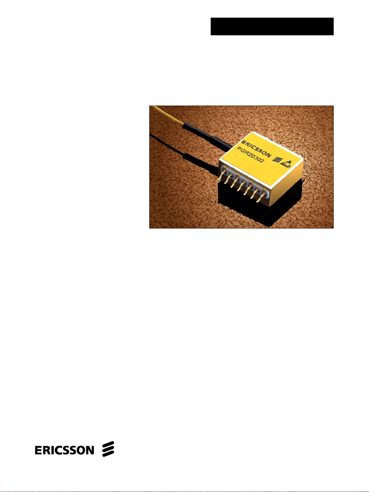
Figure 1. Block diagram
Pin connection
1. GND
2. Vpin (+5V)
3. GND
4. Vss (-5.2V)
5. GND
6. NC
7. GND
8. GND
Lead 1
FIBER
PIN
PREAMP
9. GND
10. Data Out (AC-coupled)
11. Data_Not Out (AC-coupled)
12. GND
13. Vdd (+5V)
14. NC
Case RF (and DC) GND
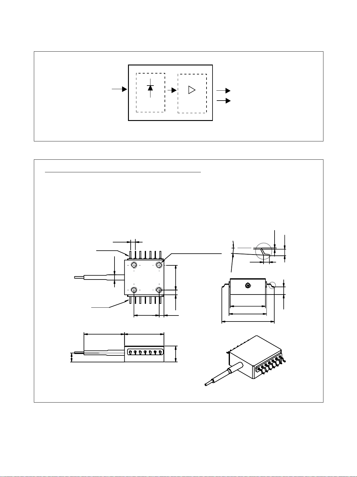
2.54
4x M3 depth min 2.54
ø 2.7
12.7
DATA
DATA_NOT
°
- 8
°
2
1.1
0.25
A
1.3
A
4.5
Figure 2. Pin description
2
Lead 14
20.5
±0.3
12.7
20.2
2.5
2.6
8
17.9
19.2
25.4
+0
-0.55
3.9
 Loading...