

Ericsson PCS Series Maintenance Manual
LBI-38957A
Maintenace Manual
PCS
403-512 MHz
Synthesized Portable Radio
ericssonz
Table of Conte n t s
Front Assembly (Front Cap Assembl y &
Audio Logic Board) . . . . . . . . . . . . . . . . . . . . . LBI-38975
Rear Assemb ly (RF Board) . . . . . . . . . . . . . . . . . LBI-38276
Service Section . . . . . . . . . . . . . . . . . . . . . . . LBI-38661

LBI-38957
NOTICE!
This manual cover s Ericsson a nd Ge ne ral Ele ctr ic prod uc ts manu fa cture d and sol d by Ericsson Inc .
NOTICE!
Repairs to this equipment should be made only by an authorized service technician or facility designated by the supplier. Any repairs, alterations or substitution of recommended parts made by the user to this equipment not approved
by the manufacturer could void the user’s authority to operate the equipment in addition to the manufacturer’s warranty.
NOTICE!
The software contained in this device is copyrighted by the Ericsson Inc. Unpublished rights are reserved under the
copyrig ht laws of t he United Sta te s.
This manual is published by Ericsson Inc., without any warranty. Improvements and changes to this manual necessitated by typographical errors, inaccuracies of current information, or improvements to programs and/or equipment,
may be made by Ericsson Inc. , at any time and without notice. Such changes will be incorporate d into ne w editions of
this manual. No part of this manual may be reproduced or transmitted in any form or by any mean s, electro nic or mechanical, including photoc opying and recordi ng, for any purpose, without the ex pre s s writte n permissio n of Ericsson
Inc.
Copyright © April 1994, Ericsson GE Mobile Communications Inc.
2

LBI-38957
TABLE OF CONTENTS
Page
SPECIFICAT IONS . . . . . . . . . . . . . . . . . . . . . . . . . . . . . . . . . . . . . . . . . . . . . . . . . . 4
FCC Filing Data . . . . . . . . . . . . . . . . . . . . . . . . . . . . . . . . . . . . . . . . . . . . . . . . . 4
General . . . . . . . . . . . . . . . . . . . . . . . . . . . . . . . . . . . . . . . . . . . . . . . . . . . . . . 4
Transmitter . . . . . . . . . . . . . . . . . . . . . . . . . . . . . . . . . . . . . . . . . . . . . . . . . . . . 5
Receiver . . . . . . . . . . . . . . . . . . . . . . . . . . . . . . . . . . . . . . . . . . . . . . . . . . . . . 5
OPTIONS AND ACCESSORIES . . . . . . . . . . . . . . . . . . . . . . . . . . . . . . . . . . . . . . . . . . . 6
DESCRIPTI O N . . . . . . . . . . . . . . . . . . . . . . . . . . . . . . . . . . . . . . . . . . . . . . . . . . . . 9
Radio Programming . . . . . . . . . . . . . . . . . . . . . . . . . . . . . . . . . . . . . . . . . . . . . . . 9
Assembly . . . . . . . . . . . . . . . . . . . . . . . . . . . . . . . . . . . . . . . . . . . . . . . . . . . . . 9
Standard Features . . . . . . . . . . . . . . . . . . . . . . . . . . . . . . . . . . . . . . . . . . . . . . . . 10
CONTROLS AND INDICATORS . . . . . . . . . . . . . . . . . . . . . . . . . . . . . . . . . . . . . . . . . . 11
Controls . . . . . . . . . . . . . . . . . . . . . . . . . . . . . . . . . . . . . . . . . . . . . . . . . . . . . 11
Indicators . . . . . . . . . . . . . . . . . . . . . . . . . . . . . . . . . . . . . . . . . . . . . . . . . . . . . 13
Tran smit Mode . . . . . . . . . . . . . . . . . . . . . . . . . . . . . . . . . . . . . . . . . . . . . 13
Receive Mode . . . . . . . . . . . . . . . . . . . . . . . . . . . . . . . . . . . . . . . . . . . . . 13
Alert Tones . . . . . . . . . . . . . . . . . . . . . . . . . . . . . . . . . . . . . . . . . . . . . . . 13
RADIO OPERATION . . . . . . . . . . . . . . . . . . . . . . . . . . . . . . . . . . . . . . . . . . . . . . . . . 14
To Receive A Message . . . . . . . . . . . . . . . . . . . . . . . . . . . . . . . . . . . . . . . . . . . . . . 14
T o Send A Message . . . . . . . . . . . . . . . . . . . . . . . . . . . . . . . . . . . . . . . . . . . . . . . 14
To Place A DTMF Call . . . . . . . . . . . . . . . . . . . . . . . . . . . . . . . . . . . . . . . . . . . . . 14
OPERATIONAL FEAT URES . . . . . . . . . . . . . . . . . . . . . . . . . . . . . . . . . . . . . . . . . . 14
Automatic Number Identification . . . . . . . . . . . . . . . . . . . . . . . . . . . . . . . . . . . 15
T yp e 99 Tone . . . . . . . . . . . . . . . . . . . . . . . . . . . . . . . . . . . . . . . . . . . . . . 15
Channel Busy L ock-Out . . . . . . . . . . . . . . . . . . . . . . . . . . . . . . . . . . . . . . . . 17
SCAN OPERATION . . . . . . . . . . . . . . . . . . . . . . . . . . . . . . . . . . . . . . . . . . . . . . . . . 17
Scan Vocabulary . . . . . . . . . . . . . . . . . . . . . . . . . . . . . . . . . . . . . . . . . . . . . . . . . 17
Pre-Scan Operation . . . . . . . . . . . . . . . . . . . . . . . . . . . . . . . . . . . . . . . . . . . . . . . 18
Scan Opera ti ng Modes . . . . . . . . . . . . . . . . . . . . . . . . . . . . . . . . . . . . . . . . . . . . . . 18
Simple SCAN . . . . . . . . . . . . . . . . . . . . . . . . . . . . . . . . . . . . . . . . . . . . . 18
Priority SCAN . . . . . . . . . . . . . . . . . . . . . . . . . . . . . . . . . . . . . . . . . . . . . 19
Scanning for Channel Guard . . . . . . . . . . . . . . . . . . . . . . . . . . . . . . . . . . . . . . 19
TONE PROGR AMMING . . . . . . . . . . . . . . . . . . . . . . . . . . . . . . . . . . . . . . . . . . . . . . . 20
GE Type 99 Format . . . . . . . . . . . . . . . . . . . . . . . . . . . . . . . . . . . . . . . . . . . . . . . 20
Motorola Form at . . . . . . . . . . . . . . . . . . . . . . . . . . . . . . . . . . . . . . . . . . . . . . . . . 21
Individual Call . . . . . . . . . . . . . . . . . . . . . . . . . . . . . . . . . . . . . . . . . . . . . 21
Group Call (Quick Cal l For ma t ) . . . . . . . . . . . . . . . . . . . . . . . . . . . . . . . . . . . . 21
Channel Guard . . . . . . . . . . . . . . . . . . . . . . . . . . . . . . . . . . . . . . . . . . . . . . . . . . 23
Replacement Of Battery Pack . . . . . . . . . . . . . . . . . . . . . . . . . . . . . . . . . . . . . . . . . . 24
To Remove the Batte ry Pack from the Radio . . . . . . . . . . . . . . . . . . . . . . . . . . . . . 25
To Re-Connect the Batte r y Pack to the Radio . . . . . . . . . . . . . . . . . . . . . . . . . . . . 25
RECHARGING THE BATTERY PAC KS . . . . . . . . . . . . . . . . . . . . . . . . . . . . . . . . . . . 25
INTRINSICALLY SAFE USAGE . . . . . . . . . . . . . . . . . . . . . . . . . . . . . . . . . . . . . . . 25
Reduced Capacity in Nickel/Cadmium Batteries . . . . . . . . . . . . . . . . . . . . . . . . . . . 25
Disposal . . . . . . . . . . . . . . . . . . . . . . . . . . . . . . . . . . . . . . . . . . . . . . . . 26
MECHANICAL PAR T S B RE AKDOWN . . . . . . . . . . . . . . . . . . . . . . . . . . . . . . . . . . . . . . 27
MECHANICAL PAR TS LIST . . . . . . . . . . . . . . . . . . . . . . . . . . . . . . . . . . . . . . . . . . . . 28
3

LBI-38957
SPECIFICATIONS*
FCC FILING DATA
Transmitter/Receiver
FCC Identifier
403-440 MHz AXA9MZ-PCSU1
440-470 MHz AXA9MZ-PCSU2
470-512 MHz AXA9MZ-PCSU3
FCC Part Numbers 22, 74, 80, 90, 95
GENERAL
Frequency Ra ng e 403-512 MHz
RF Power Range 1-4 Watts
Input Voltage 6.0 to 9.0 Volts
Channel Capacity 2, 8, or 16 Channels
Frequency Sprea d (Full Perform anc e)
TX Full Split
RX 20 MHz of S plit
Frequenc y Stab il ity ±5 PPM
Channel Spacing 25 kHz
Dimensions (less antenna) H x W x D
with 1200 mAh Battery 7.4 x 2.8 x 1.57 inches (18.8 x 7.11 x 4.0 cm)
with 1700 mAh Battery 8.8 x 2.8 x 1.57 inches (22.35 x 7.11 x 4.0 cm)
Weight
Radio (le ss bat te ry ) 11 ounc e s
1200 mAh Battery 9 ounces
1700 mAh Battery 13.5 ounces
Ambient Temperature Ran ge -30° to +60°C (-22° to +140° F)
Battery Drain (7.5 VDC )
Receiver Standby 70 milliamperes
Rece iv er Full Audio 250 milliamp er es
Transm it (@4 watts) 1.7 amperes
Transm it (@2 watts) 1.3 amperes
Batte ry L ife (be t wee n c harges ) High Ca pa ci ty Extra Hi gh Ca pacity
Hi Power (5-5-90% duty cycle ) 8.0 hours 11.0 hour s
Lo Power (5-5-90% dut y cycle ) 9.0 hours 13.0 hours
4

TRANSMITTER
Power Output
Hi Power 4 watts
Lo Power 2 watts (adjustabl e to 1 watt)
Conducted Spu rio us -66 dB (-30 dBm)
Modulation Deviat ion ±5.0 kHz (maximum)
FM Noise (companio n re cei ve r method) -45 dB
Power Adjust Range 1 to 4 Watts
Distortion 5% (maximum)
Deviation Symmetry 0.1 kHz
RF Load Im pedance 50 Ohms
Carrie r At tac h Time 35 milli sec onds
Audio Attach T ime 35 millisecond s
RECEIVER
LBI-38957
Audio Output (EI A) 0.5 W at ts (<5% distortion)
Sensitivity
12 dB SINAD (EIA) -119 dBm (0.25 µV)
Selectivity
(EIA 2-signal method) -65 dBm @ ±25 kHz
Spurious Response -70 dB
Intermodulation -65 dB
Hum and Noise
Squelched -80 dB
Unsquelched -48 dB
Modulation Acceptan ce ±7 kHz
Frequency Respon se Within +2 dB and -8 dB of a standard 6 dB/octa ve
de-empha sis cu rve from 300 to 3000 Hz (E IA) .
RF Input Impedanc e 50 Ohms
* These spec i fications are int ended primarily for use by servic e p er sonnel. Refer to the appropriate Specification Sh ee t for
com ple t e specific at io n s.
5
LBI-38957
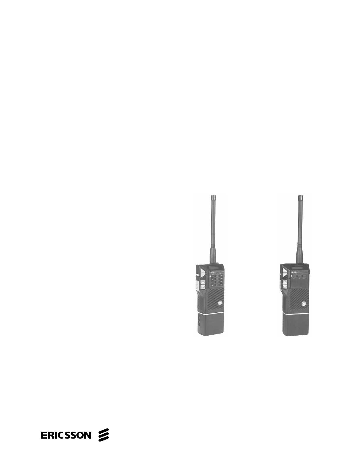
OPTIONS AND ACCESSORIES
BATTERY PACKS
PCP A1 J
High Ca pacity
(19A705293 P1)
Stan dar d
CHISS1 (120 VAC)
CHISS2 (230 VAC)
PCPA1K
Extra High Capacity
(19A705293P2)
DESK CHARGERS
PCPA1L
Extra High Capacity
(19A705293P3)
Factor y Mutual App rove d
Rapid
CHIRS1 (120 VAC)
CHIRS2 (230 VAC)
ANTENNA (Helical)
PCNC3C 19B801 620P1 (403- 440 MHz )
PCNC3D 19B801 620P2 (440 -470 MHz) Fa ctor y Mut ua l Appro ved
PCNC3F 19B801620P3 (470-512 MHz)
6
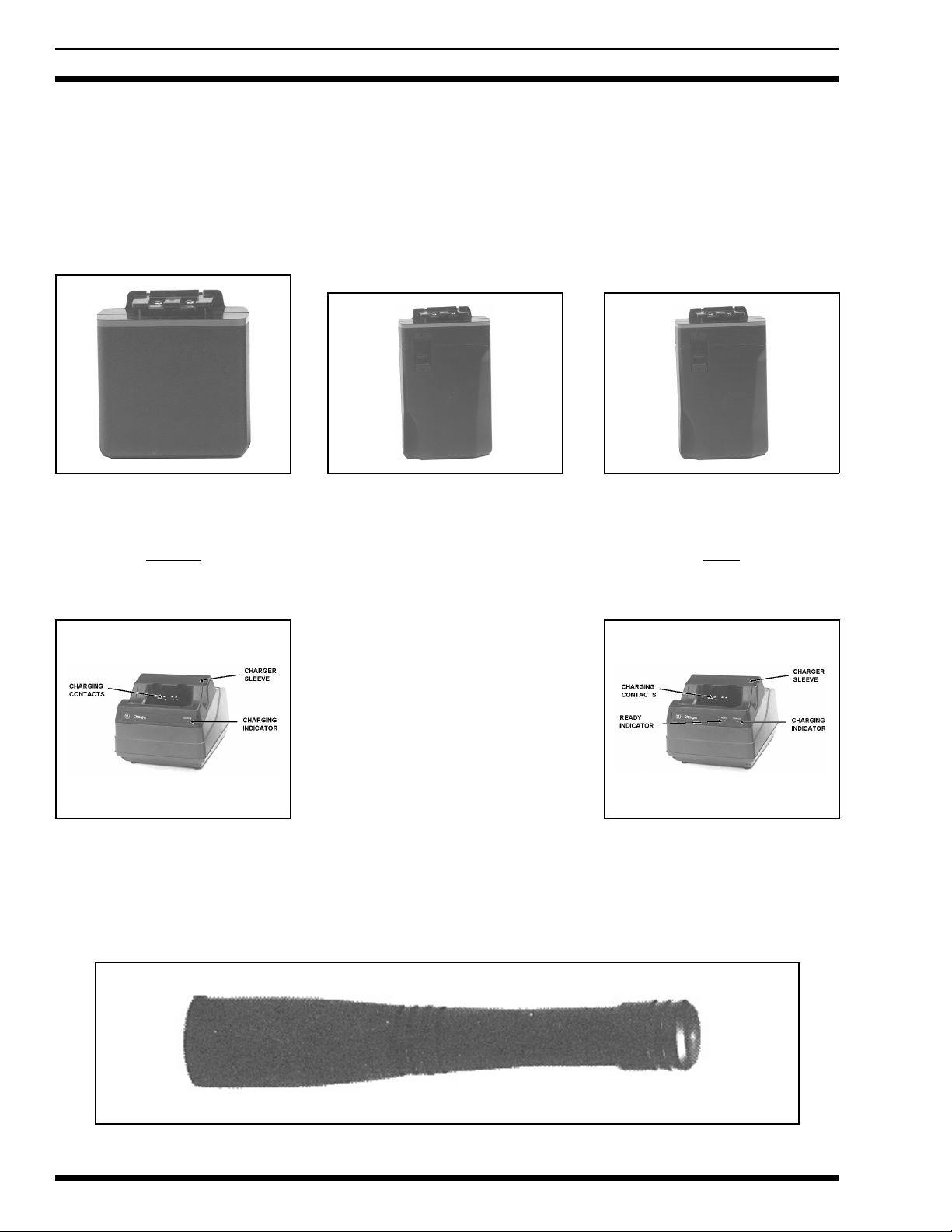
OPTIONS AND ACCESSORIES
ANTENNA (Flexible Whip)
PCNC3A 19B801621P1 (403-4 70 MHz ) Factory Mutual App rove d
PCNC3B 19B801621P2 (4 70-5 12 MHz) Factory Mutu al App rove d
CARRYING ACCESSORIES
Belt Clip
PCHC1C
(Option Package 19B 2332 41G1)
(Modifica tion Kit 19A14 4704 G1)
LBI-38957
(contin ued)
(Factory Mutua l Approved )
Swivel Plate
PCHC1D
(Belt Loop 19B 226627G2)
(Swivel Option 19B233243G1)
Earpiece Kit
PCZM1A
Incu des PCPA1C
Speaker/Microphone
PCAE1X
Accessorie s Conn ec t or
PCAC1C (19C851752P7)
7
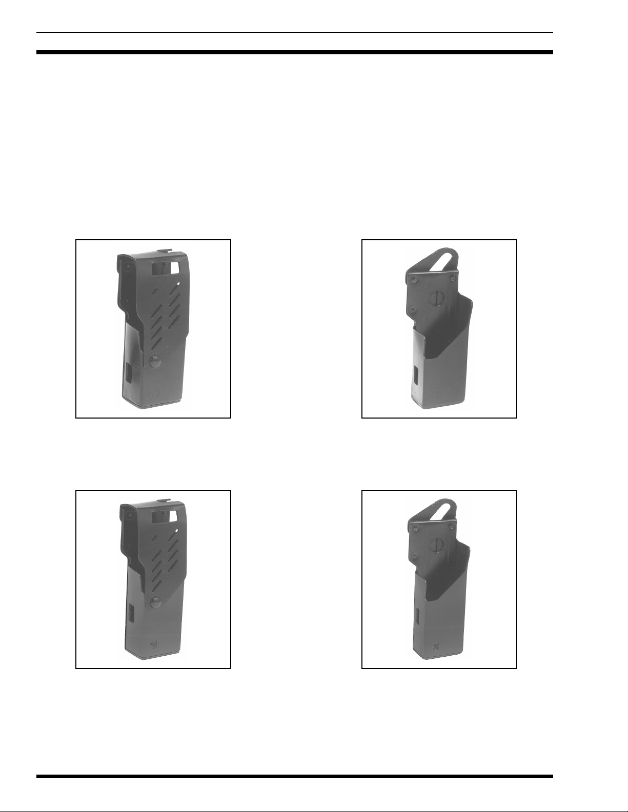
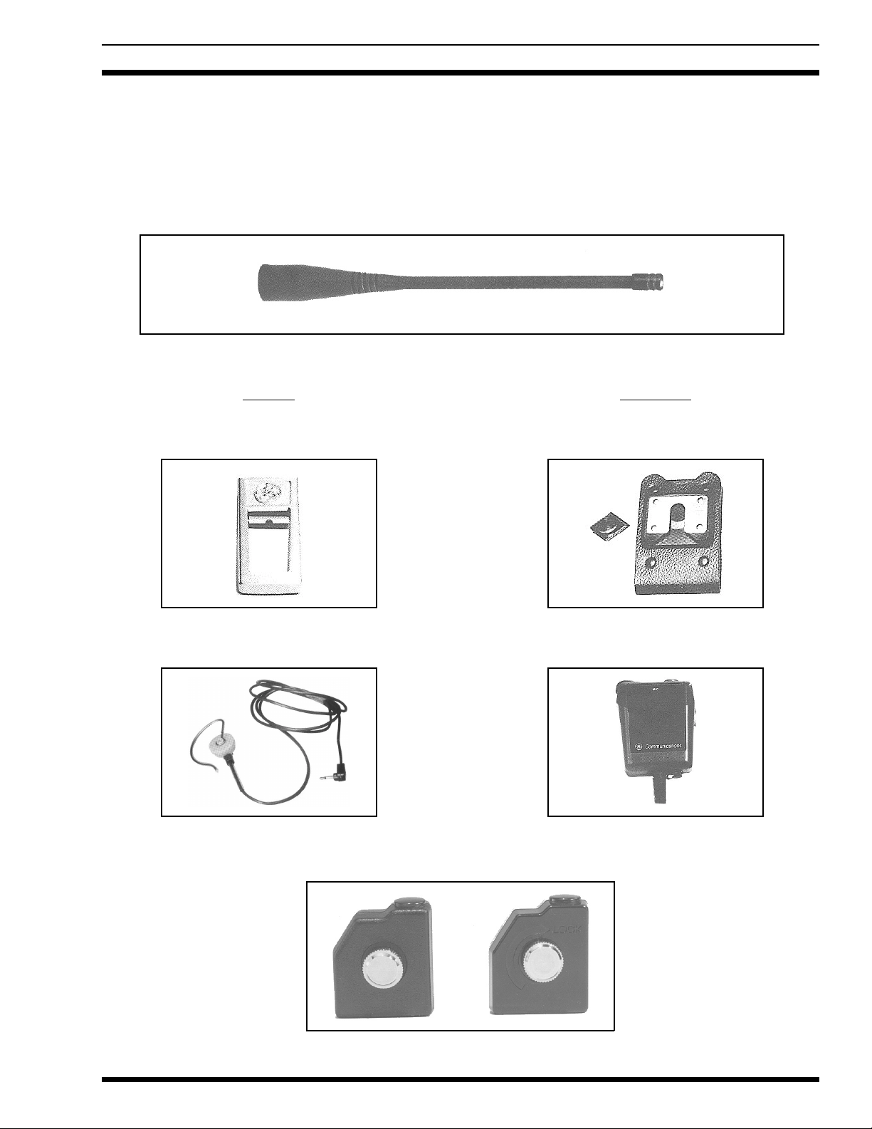
LBI-38957
OPTIONS AND ACCESSORIES
(contin ued)
CARRYING CASES
(Factory Mutua l Approved )
PCHC5S
High Ca pa c it y Ba tt e ry Pack
Full Cover 19D902456P15
PCHC5U
Extra High Ca pa c it y Ba tt e ry P a ck
Full Cover 19D902456P18
PCHC5T
High Capacity Battery Pack
Retaining Stra p 19 D9024 56P7
PCHC5V
Extra High Capacit y Ba tt er y Pack
Retaining Stra p 19 D9024 56P7
8

When the battery is low, the low battery indicator
(BAT) is displayed on the LCD and an audio alert is
sounded every 7.5 minute s. When the ba tt e ry is su fficiently low to cause improper operation, the radio
micropro cessor te rm i nate s all ope ra tion .
LBI-38957
DESCRIPTION
The PCS Portable radio is a small, r uggedly constr ucted,
two-way FM radio, housed in an aluminum and Lexan case.
The UHF synthesized radios operate in the 403-512 MHz
range and they can be purchased with 2-, 4-, 8-, or 16-channel operation.
Operating controls for the radio are provided through a
rubber keypad on the side and front (a three-button keypad
on the Standard version). All keypad switches have a good
tactile feel and are sealed to provide weather protection.
When turned "ON," the radio po wers-up on the last chann el
used and at the last volume setting. The operating controls,
UDC, and battery pack are shown in Figure 1.
All the PCS radios are equipped with a Universal Device Connector (UDC) for connecting external options and
for programming the radios. The radios are programmed
using a personal computer and programming interface box
that connects to the UDC. The UDC is covered with a rubber cover for improved weather prot ect ion .
The PCS uses a BNC antenna connector. The antenna
base is overmolded to fit flush aga in st the housing for added
weather pr o tecti on .
The radio battery pack securely latches in place at the
bottom of the radio. The radio ON/OFF switch is located
on the battery pack.
A Liquid Crystal Display (LCD) on the front of the radio shows the selected channel, volume level, SCAN mode
(SCN)*, and priority level (P1, P2, or S). The 2-channel radio uses the "P1" and "P2" pixels for high and low transmit
power indicators, respectively. In addition, the "S" pixel is
used to indicate "Talkaround" mode. The LCD also has a
transmit (TX) indicator, a low battery voltage indicator
(BAT), and a Type 99 paging (PG) indicator. There are
eight (8) levels o f volume represe nt ed by the fou r (4) bars i n
the LCD. Each bar represents two (2) volume levels. The
LCD module is backlit for night viewing and is mounted in
a rubber seal for wea ther protecti on.
The radio is shipped from the factory with the high
power level set to 4 watts and the low power level set to 2
watts.
NOTE
RADIO PROGRAMMING
Each of the 4-, 8- or 16-channel radios can be programmed for SCAN operation, and HOME Channel or
Emergency Channel, in addition to the Tone or Digital
Channel Guard, Squelch Tail El imination (STE), Type 99
Tone Decoding, Automatic Number Identification (ANI),
Channel Busy Lock-Out, and HI/LO transmit power level
available on the conventional 2-channel radio. These options can be programmed on a channel-to-channel basis.
Two different T99 Tone tables can be programmed into the
PCS. Each channel is capable of Individual, Group, or Super Group Decode.
Other programmable features include: Carrier Control
Timer (CCT), display backlighting, and alert beep options.
These features can be programmed, as desired, to meet system re quirements.
Refer to the programming manual (TQ3366) for complete programming instructions.
ASSEMBLY
The PCS personal radio consists of an RF board
mounted in the rear a ssembly, an audio/logic boa rd mount ed
in the front assembly, and a control frame assembly.
The RF board contains all transmit, receive, and synthesizer circuits. The audio/logic board contains all transmit
audio and recei ve a udio ci rcuit s as wel l as all lo gic a nd c on trol circuits. A microprocessor on the audio/logic board
generates and decodes all tones used in Channel Guard or
Type 99 tone signalling.
The control frame assembly mounts in the radio front
cover and pro vid es th e fo llowin g func t ion s:
*SCAN applies to the 4-, 8- and 16-c ha nn el PCS radio s.
• Audio/Logic board interface.
• Microphon e and spea ke r conne c tions.
• Houses the channel up/down, volume up/down,
monitor, and PTT switche s.
9
 Loading...