

Ericsson PBL38085 Datasheet
PBL 380 85
July 1999
PBL 380 85
Integrated circuit for transformerless
driving of battery powered
EL (electroluminicent) lamps
Description.
PBL 380 85 is a monolithic integrated circuit for supplying power to an EL
(electroluminicent) lamp. This is intended to replace the LCD background illumination
system in battery powered handheld equipment with a low power EL- lamp. Especially
suitable for mobile phones where current saving is highly important, as background
illumination for both LCD and keyboard. Output voltage max. 190V, min. 170V at max.
2mA constant current charge / discharge of the EL- lamp. Application dependent
parameters such as charge / discharge current are set by an external resistor. Two control
signals are needed one for the switcher and one for the lamp.The output voltage is set
under 170V by the duty cycle and the switching frequency of the control signal, over 170V
by an amplitude limiter that switches the switcher off. The switching frequency is app. 50
kHz. The light intensity is controlled by the dutycycle of the switcher control signal. The
lamp control signal is divided by two by the circuit. The wave form of the output AC-signal
is either triangular or trapezoid depending of the capacitance of the EL-lamp, charge /
discharge current and frequency of the lamp control signal.The triangular or trapezoid
wave form of the EL-lamp driving voltage and the high switching frequency minimizes
audible noise from the lamp and also reduces upcoming electrical noise and harmonics.
+supply
Key features.
• Minimum number of external
components for function: 1 choke, 1
filter-capacitor and 1 resistor.
• Easy adaption to various lamp
specifications.
• Easy dimming function by
controlling the duty cycle.
• Extensive current saving feature
compared with LEDs.
• Power down function <<1µA.
• Supply voltage down to 3V.
• Comes in a 3x3 mm package
• Lights up to 20nF
area depending on lamp
parameter nF/cm
lamp capacitance
2
.
switcher control
signal
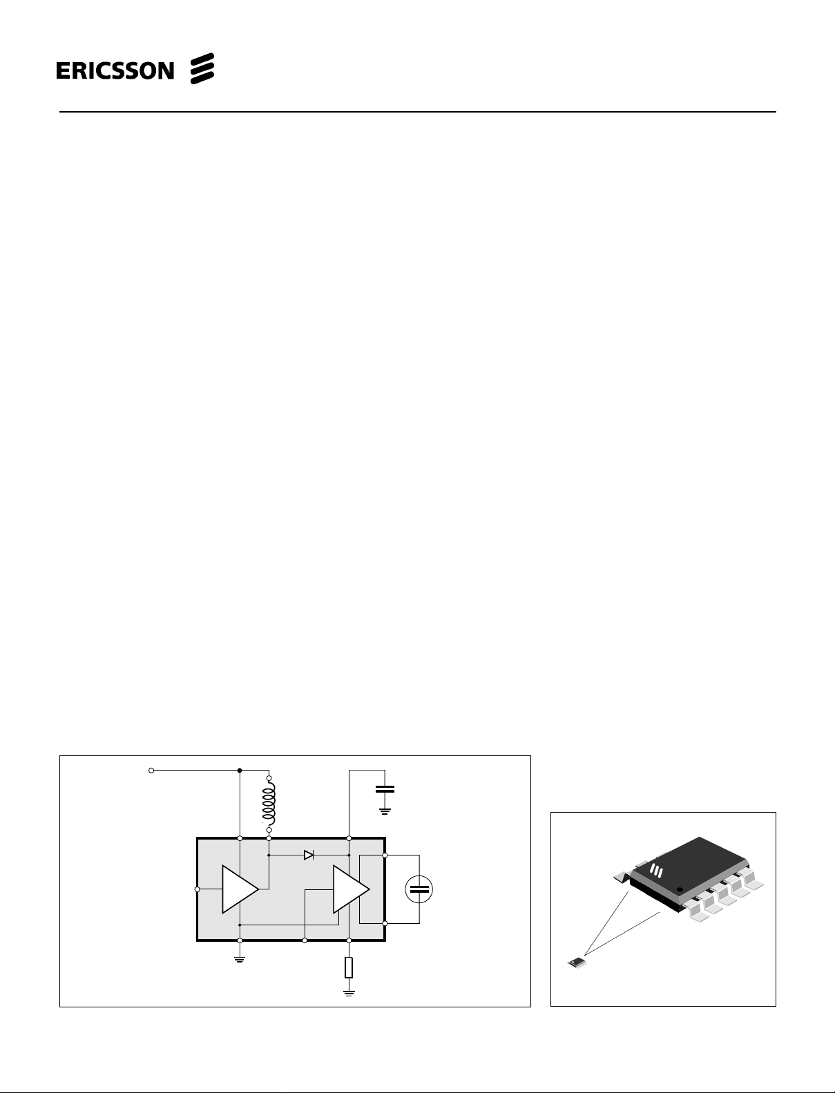
Functional diagram.
510 9
8
2
PBL 380 85
1
lamp control
signal
6
34
Pekka 11.11-98
EL-lamp
PBL 380 85
True size
10 - pin plastic mini SOP package
PBL 380 85
1

PBL 380 85
Maximum Ratings
Parameter Symbol Min. Max. Unit
Supply voltage, continuous V+ 0 90 V
All inputs (zener protection) 6.5 V
Operating temperature range T
Storage temperature range T
Amb
Stg
Electrical Characteristics
At T
= 25°C V+ = 2.75 V if no otherwise stated. For further conditions see figure.
Amb
Parameter Condition Symbol Min. Typ. Max. Unit
-30 +85 °C
-55 +150 °C
Battery voltage V
V
quiescent curren V+ off 0.1 µA
BAT
Bat
1.5 3.6 65* V
Logic supply voltage V+ 2.4 2.75 5.5 V
V+
operating supply current SC + LC 50% 50%
V+
quiescent supply current SC = 0 ; LC = 0 5 µA
Logic low level input voltage 0.3xV+ V
Logic high level input voltage 0.7xV+ V
Logic low level input current -100 100 µA
DC/DC converter:
Booster output voltage, int.limited 90 V
Switch transistor sat. voltage 80mA inductor current 0.6 V
Switching frequency, set by the
SC-signal frequency 50 kHz
H - BRIDGE:
Output voltage EL1 - EL2 170 V
pp
Output unbalance voltage EL1 - EL2 -5 +5 V
Output sink/source current range
lower limit 0.1 mA
Output sink/source current range
upper limit 1.5 mA
Output current x resistance product
( note1) I
SET
* R
SET
9.5 10 10.5 V
Output drive frequency, set by the
LC-signal frequency 250 Hz
Note1: This product is the EL1/EL2 output current multiplied by the resistor value connected to I
dependent of the V+ voltage asit is a quota of that voltage.
* Battery voltage max. 65V requires correctly chosen duty cycle and inductance.
2
. Voltace at the I
SET
SET
pin is
 Loading...