

Ericsson EDACS Monogram Series, KRD 103 123/2 Installation Manual
Installation Manual
®
EDACS
Monogram
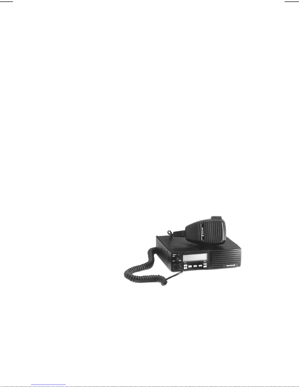
MOBILE RADIO 800 MHz
Series
ericssonz

TABLE OF CONTENTS
Page No.
INTR ODUCT ION . . . . . . . . . . . . . . . . . . . . . . . 3
UNPACKING AND CHECKING E QUI PMENT . . . . . . . 3
MOBILE EQUIPMENT . . . . . . . . . . . . . . . . . . 3
STATION EQUIPMENT (In addition to Radio) . . . . . 3
PLANNING THE INSTALLATION . . . . . . . . . . . . . . 5
EQUIPMENT REQUIRED . . . . . . . . . . . . . . . . 5
INSTALLATION IN VEHICLES POWERED
BY LIQUEFIED (LP) GAS . . . . . . . . . . . . . . . . 6
INSTALLATION . . . . . . . . . . . . . . . . . . . . . . . . 7
RUNNING CABLE S . . . . . . . . . . . . . . . . . . . 7
RUNNING T HE POWER CABLE . . . . . . . . . . . . 7
MOUNTING THE RADIO . . . . . . . . . . . . . . . . 8
MICROPHONE . . . . . . . . . . . . . . . . . . . . . . 8
OPTION INSTALLATION . . . . . . . . . . . . . . . . . . . 9
ANTENNA - OPTION MGAN1D . . . . . . . . . . . . 9
NOISE SUPPRESSION KIT - OPTION MGPD1A . . 10
EXTERNAL SPEAKE R KIT - OPTION MGZM9F . . 10
ALARM POWER RELAY - OPTION MGSU1C . . . . 12
DESKTOP STATION INSTALLATION . . . . . . . . . . . 12
INSTALLATION OF THE POWER SUPPLY . . . . . 14
NO TICE!
This manual covers Ericsso n and General Electr ic products
manufactured for and sold by Ericsson Inc.
NOTICE!
Repairs to this equipment should be made only by an authorized service
technician or facility designated by the supplier. Any repairs, alterations
or substitution of recommended parts made by the user to this equipment
not approved by the manufacturer could void the user’s authority to
operate the equipment in addition to the manufacturer’s warranty.
This manual is published by Ericsson Inc., without any warranty. Improvements and changes to this manual necessitated by
typographical errors, inaccuracies of current information, or improvements to programs and/or equipment, may be made by
Ericsson Inc., at any time and without notice. Such changes will be incorporated into new editions of t his manual. No part of this
manual may be reproduced or transmitted in any form or by any means, electronic or mechanical, including photocopying and
recording, for any purpose, without the express written permission of Ericsson Inc.
Copyright© November 1996, Ericsson Inc.
2

INTRO DUCTION
This manual contains installation instructions for the EDACS
MONOGRAM SERIES Mobile Radio, Desktop Station, and associated
accessories. These instructions cover the mounting and cabling of the mobile
radio and station setup. Interconnection diagrams are located at the back of the
manual for your reference. Before installation, the radio should be
programmed using an IBM compatible personal computer and the following
items:
Programming Cable RPM 113 2510/1
Programming Software AE/LZY 213 766
UNPA CKING AND CHECKING EQ UIPMENT
The EDACS MONOGRAM SERIES Radio may be provided for either
station or mobile applications. When ready for installation, carefully unpack
the radio and identify each item in the shipping container. If damage has
occurred to the equipment during shipment, file a claim with the carrier
immediately. The available options for the Mobile Radio are identified in
Table 1.
MOBILE EQUIPMENT
• EDACS MONOGRAM SERIES Mobile Radio . . KRD 103 123/2
• Microphone . . . . . . . . . . . . . . . . . . . . . MGMC5X
• Microphone Hangar and Mounting Hardware . . . TBD
• PowerCable,8 feet . . . . . . . . . . . . . . . . . RPM 113 2509/1
• Mobile Mounting Bracket
and Ass oc iated Hardware . . . . . . . . . . . . . SXA 120 4253/1
• Operator’s Manual.. . . . . . . . . . . . . . . . . AE /LZ T 12 3 1920
• Installation Manual . . . . . . . . . . . . . . . . . AE/LZT 123 1921
STATION EQUIPMENT (In addition to Radio)
• Power supply . . . . . . . . . . . . . . . . . . . . MGPS5V
• Station Microphone . . . . . . . . . . . . . . . . MGMG7A
3

Table 1 - OPTIONAL EQUIPMENT
Option Description
MGAN1D Antenna
MGPD1A Noise Suppression Kit
MGZM9F External Speaker, MIL-STD-810C & D, 5” x 5”
External Speaker Cable, 9 inches
MGSU1C Alarm Power Relay Kit
MGMC5Z DTMF Microphone
MGMC5X Microphone
Figure 1 - Radio Components and Mounting Hardware
4
PLANNING THE INSTALLATION
Before starting, plan the radio installation carefully so that it will be:
• safe for the operator and passengers.
• convenient for the operat or to use.
• neat.
• protected from water damage.
• easy to service.
• out of the way of auto mechanics.
It is suggested that the radio be installed by one of the many Authorized
Service Centers located throughout the United States. These experienced
service centers can provide a proper radio installation and make any final
adjustments that may be needed.
WARNING
Interference with Vehicular Electronics - Electronic fuel injection
systems, electronic anti-skid braking systems, electronic cruise controls
systems, etc., are typical of the types of electronic devices which may
be prone to malfunction due to the lack of protection from radio
frequency energy present when transmitting. If the vehicle contains such
equipment, consu lt the dealer for the make of vehicle an d en list his a i d
in determining if such electronic circuits will perform normally when
the radio is transmitting.
EQUIPMENT REQUIRED
The equipment required for installing the mobile radio is listed below:
• Electric drill for drilling mounting holes.
• Drills and circle cutters as follows:
• No.25 (0.149 inch) drill for No.10 self-tapping screws.
• 5/8-inch Drill or circle cutter for power cable.
• 3/4-inch circle cutter, hole saw or socket punch for antenna
(optional).
• Phillips and flat-blade screwdrivers, and 1/4-inch and 5/16-inch hex-
head drivers for mounting sc rews.
5
 Loading...