

Page 1
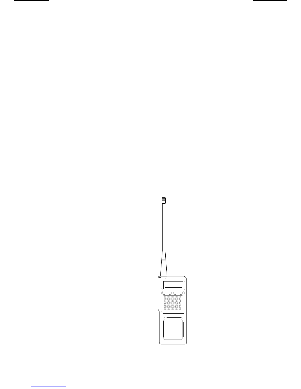
Operator’s Manual
Two-Way FM
Transceiver
KRD 103 117/1
KRD 103 117/3
ERICSSONZ
s
L/O
s
SCAN
Page 2

NOTE!
Repairs to this equipment should be made only by an
authorized service technician or facility designated by the
supplier. Any repairs, alterations or substitution of
recommende d parts made by the user to thi s equipm ent not
approved by the manufacturer could void the user’s authority
to operate the equipmen t in additio n to the manufact urer’s
warranty.
This manual is published by
changes to this manual necessitated by typographical errors, inaccuracies of current
informatio n, or impro vem ents t o pro gram s and/ or equ ipm ent, may be mad e by
, at any time and without n otice. Such cha nges will be incor porate d int o ne w edit ions o f
Inc.
this manual. No par t of this manu al may be reprod uced or tr ansmitte d in any fo rm or by any
means, electronic or mechanical, including photocopying and recording, for any purpose,
without the express written permission of
Copyright © September 1994, Ericsson Inc.
Ericsson In c.
Ericsson Inc.
- 2 -
, without an y warranty. Improv ements and
Ericsson
Page 3

Table of Contents
Safety Information . . . . . . . . . . . . . . . . . . . 4
Controls & Functions . . . . . . . . . . . . . . . . . . 5
Introduction . . . . . . . . . . . . . . . . . . . . . . . 6
Congratulations . . . . . . . . . . . . . . . . . . . . . 6
Description . . . . . . . . . . . . . . . . . . . . . . . 6
Service . . . . . . . . . . . . . . . . . . . . . . . . . 6
Features . . . . . . . . . . . . . . . . . . . . . . . . 6
Unpacking . . . . . . . . . . . . . . . . . . . . . . . . 8
Getting Started . . . . . . . . . . . . . . . . . . . . . 5
Chargin g the Battery . . . . . . . . . . . . . . . . . . 9
Attaching/Removing the Battery . . . . . . . . . . . . 9
Installing the Antenna . . . . . . . . . . . . . . . . . 10
Attaching the Belt Clip . . . . . . . . . . . . . . . . 10
Operation . . . . . . . . . . . . . . . . . . . . . . . 11
LCD Display . . . . . . . . . . . . . . . . . . . . . . 11
Transmit/Receive Indicator . . . . . . . . . . . . . . 11
Applying Power and Setting the Volume . . . . . . . 12
Receive . . . . . . . . . . . . . . . . . . . . . . . . 12
Channel Scan . . . . . . . . . . . . . . . . . . . . . 13
Dual Watch . . . . . . . . . . . . . . . . . . . . . . 13
Create a Channel Scan List
with Channel Lock Out . . . . . . . . . . . . . . . . 13
Drop Out Delay . . . . . . . . . . . . . . . . . . . . 13
Transmit . . . . . . . . . . . . . . . . . . . . . . . . 13
Transmit During Scan . . . . . . . . . . . . . . . . . 14
Transmit Time Out Timer . . . . . . . . . . . . . . . 14
Special Features . . . . . . . . . . . . . . . . . . . 15
Battery Save . . . . . . . . . . . . . . . . . . . . . 15
Function Tone . . . . . . . . . . . . . . . . . . . . . 15
Optional Accessories &
Replacement Parts . . . . . . . . . . . . . . . . . . 15
Technical Support and Service . . . . . . . . . . . . 16
Specifications . . . . . . . . . . . . . . . . . . . . . 16
Nickel Cadmium Battery Warranty . . . . . . . . . . 17
Warranty . . . . . . . . . . . . . . . . . . . . . . . . 18
- 3 -
Page 4
SAFETY INFORMATION
Through the provisions of the Occupational Safety and
Health Act (OSHA) of 1970, the United States Department
of Labor has established an electromagnetic safety standard
which app lies to the us e of two-way radio equipmen t. The
proper use o f this transcei ver will resul t in exposure below
the OSHA limit.
The following precautions shall be observed:
DO NOT
operate the transceiver of any radio equipment
with the antenna touching, or close to, the eyes, face, or
exposed body parts.
DO NOT
operate the tr ans mitter o f any radio equi pmen t
unless all the Radio Frequency (RF) connectors are
secure and any op en connectors ar e properly terminat ed.
DO NOT
operate the tr ans mitter o f any radio equi pmen t
near electrical blasting caps or in an explosive
environment.
DO NOT
let children operate any transmitter-equipped
radio equipment.
Have your radio equipment installed and serviced by a
qualified technician.
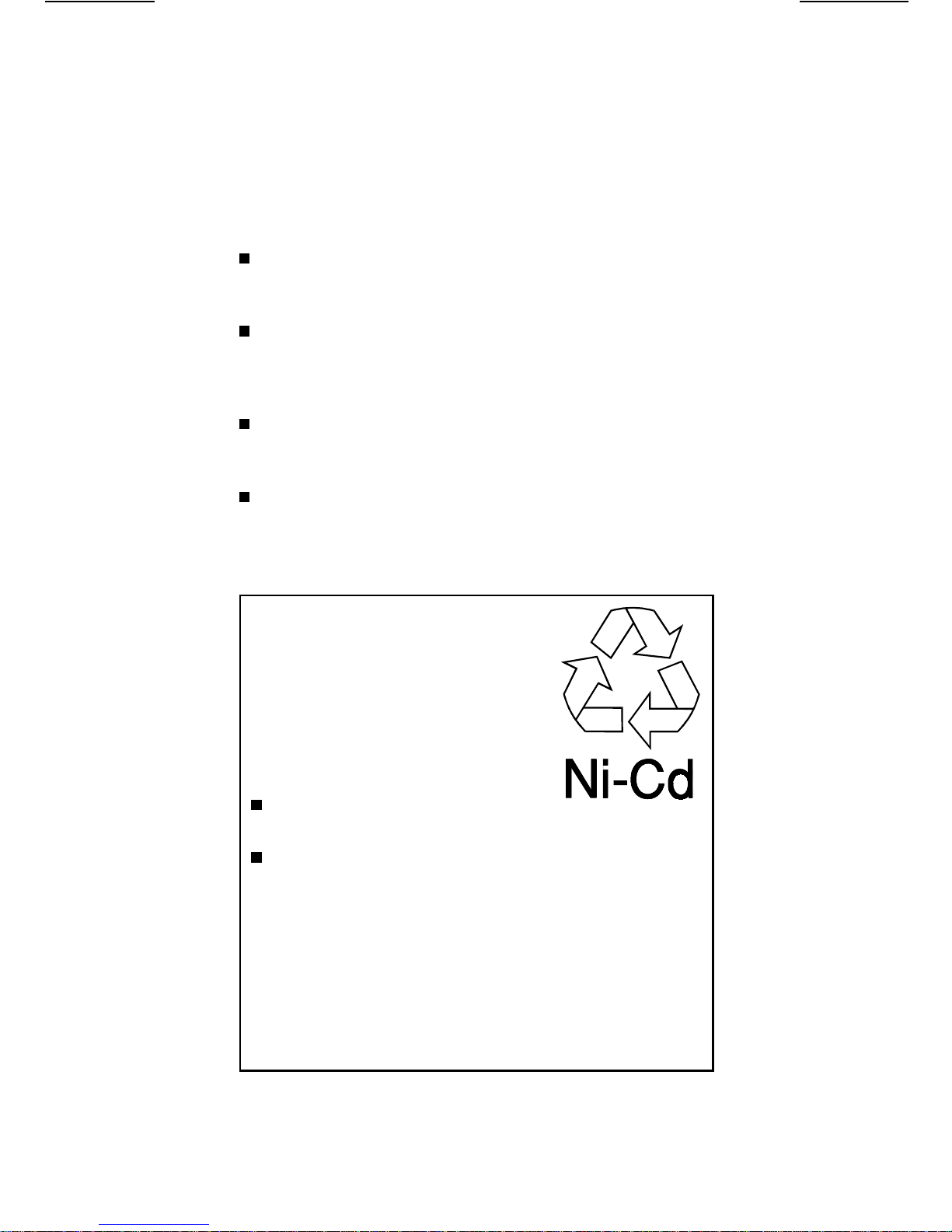
Rechargeable Nickel-Cadmium
Battery Pack Warning
This radio contains a Rechargeable
Nickel-Cadmium Battery Pack. Cadmium
is a chemical known to the State of
California to cause cancer. The
Nickel-Cadmium Battery Pack contained
in this radio may explode if disposed of in
a fire.
Do not
Nickel-Cadmium Battery Pack.
Do not
Battery Pack except with the recommended chargers.
Rechargeable Nickel-Cadmium Battery Packs
Must Be Recycled or Disposed of Properly!
Residents of Minnesota should contact 1-800-8BATTERY for
information concerning reclamation and disposal of
Rechargeable Nickel-Cadmium Battery Packs. Residents
outside of Minnesota should contact their local authorities for
information concerning reclamation and disposal of
Rechargeable Nickel-Cadmium Battery Packs.
Caution:
Ericsson I nc. does not repres ent this radio to be
waterproof. Do not use the radio in damp or high-moisture
environments.
short circuit this
charge this Rechargeable Nickel-Cadmium
- 4 -
Page 5
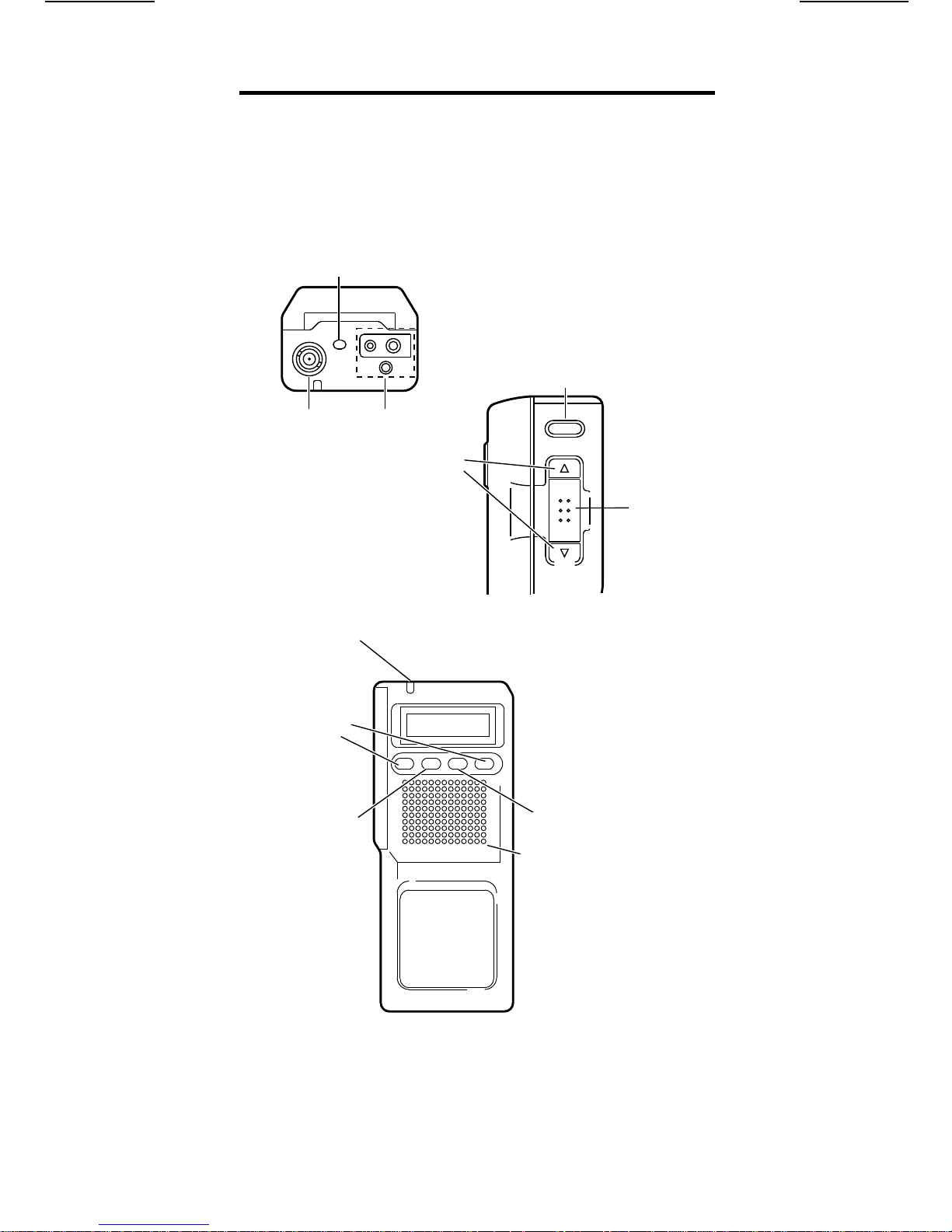
CONTROLS & FUNCTIONS
POWER Button
POWER
Monitor Key
Antenna
Connector
Transmit
Indicator
Channel Up/Down
Keys
<>
SCAN
Scan Key
External
Mic/Speaker
Jacks
s
Volume
Keys
UD
L/O
SCAN
s
MON
L/O
LockoutKey
Lockout Key
Built-In Speaker/
Microphone
PTT
PTT
(Push-to-Talk)
(Press-to-Talk)
Key
Key
- 5 -
Page 6

Introduction
Congratulations
You now own the best value in portab le radios, a profession al
communicatio ns radio . The
give you consistent, outstanding performance in
117/3
virtually all conditions and situations.
KRD 103 117/1
and
KRD 103
Your
Transceiver offers many special features. Read this
Operator’s Manual comple tely to be sure you are gett ing t he
most from the radio.
KRD 103 117/1
or
KRD 103 117/3
Two-Way FM
Description
The
KRD 103 117/1
portable Two-Way FM Transceivers. They are
microprocessor-controlled, frequency-synthesized, and
programmab le. The y are l ightw eight, rugge d, and f it easil y
in your hand.
The
KRD 103 117/1
with a maximum RF power output rating of 5 watts.
The
KRD 103 117/3
with a maximum RF power output rating of 4 watts.
and
KRD 103 117/3
operates in the 146 to 174 MHz range
operates in the 43 8 to 47 0 MHz ra nges
are 16-Channel
Service
If your ra dio does not work proper ly, take it t o a dealer for
servicing. These radios contain no user serviceable parts.
Unauthorized adjustments will void the warranty and may
cause illegal radio operation. Make sure that a qualified
technician services your radio equipment. When servicing
these radios, use only factory authorized replacement parts.
Features
Scan Mode
temporarily
External Speaker/Microphone Jacks
optional spea ker or microphone for improved op eration in
special situ ations.
Channel/Function LCD
Channel Monitor Switch
Battery Low Indicator
User-Programmable Channe l Scan Li st
TX/Busy LED
—Monitors all Channels. (You can
lock out
selected Channels.)
—Allows use of an
- 6 -
Page 7

Program Selectable (Dealer Programmable):
The Channel frequencies and options (such as Tone-Coded
Channels and Pri ority Chann el) have been pre-program med
into your radio by your dealer . Check with your dealer for
the specific features in your r adio.
Scan Dropout Delay
Transmitter Time Out Timer
Battery Save
Busy Channel Lockout
Function Beep
CTCSS/DCS/2-Tone Receive/T ran smit Code s
TX Power High/Low
- 7 -
Page 8

Unpacking
The following should be inclu ded with your two- way radio:
Transceiver Unit
Antenna
Belt Clip
Operator’s Manual (AE/LZT 123 1883)
Nickel-Cadmium Rechargeable
Battery Pack (BKB 191 207/1)
If any of these items are missing f rom the box, contact your
dealer for help.
FCC Licensing
Before you transmit with your radio, yo u mu st have the
proper license issued by the Federal Communications
Commissio n (FCC). Your dealer can tell you what is required, and can help you with all your future communication needs.
Features, specifications, and availability of optional
accessori es are all subject to change witho ut notice.
- 8 -
Page 9

Getting Started
Before you can use your radio, you must install and charge
the batter y an d in stall the antenna as follows.
Charging the Battery
Your radio is powered by a specially-designed,
nickel-ca dmium battery. You should fully charge the batter y
before operating the radio. Only use the following charger.
Model BML 161 60/1 Desktop Rapid Charger
Follow the charging instructions that come with the charger.
Also, be sure to observe the following warning/safety
information for nickel-cadmium batteries (on page 4 of this
Operator’s Manual).
Attaching/Removing the Battery
To attach the battery to the radio, align the slots in the battery
with the hooks on the radio as shown. Then, slide the battery
toward the top of the radi o un til it locks into plac e.
To remove the batt ery fr om the
radio, push the battery release
lever toward the front of the
radio and slid e th e battery
toward the bottom of the radio.
- 9 -
Page 10

Installing the Antenna
To install the antenna, align it
with the antenna connector on
the top of the radio and turn it
clockwise until it seats snugly
against the radio.
Attaching the Belt Clip
Attach the supp lied belt clip as shown.
POWER
MIC SP
uniden
- 10 -
Page 11

Operation
LCD Display
The liquid crystal display
(
) has several ind icators
LCD
that show the cu rren t op era ting
mode. The two digits show the
current selected channel. The
smaller displ ays show which
features ar e en ab led.
CALL SCAN
PRI
VOX
08
LOW BAT
DEL
DTMF
CALL
PRI
VOX
SCAN
DEL
LO BATT
Call Received with CTCSS/DCS/2-Tone Codi ng
Priority Channel
Voice-Operated Switch activated
Scanning in operation
Channel removed from Scan List
Blinks when the Battery Powe r is low
Transmit/Receive Indicator
The Transmit/Receive
Indicator shows different colors
depending upon the operation:
Transmit:
Steady RED
Transmit
Indicator
s
SCAN
L/O
s
Channel Busy:
2-Tone-Coded Signal:
Monitor ON:
Blinking RED
Blinking ORANGE
Steady ORANGE for 4 seconds
- 11 -
Page 12

Applying Power and Setting the Volume
1. Turn the radio on by
pressing the POWER
in
out
position.
position.
<
05
or
07
button to the
The display lights and
shows the last-selected
Channel numb er.
Note: To turn the radio off, release the POWER button to
the
2. Press the Channel Up or
Channel down ke y (
) to display the de sired
>
Channel numb er.
Note: I f you press and hol d either key, the ra dio changes
Channels rapidly.
3. Press the Monitor Key
).
(
M
Adjust the speaker volume
to a comfortable level by
pressing the Volume Up
) or Volume Down
(
<
) Key
(
>
Note: If you hold down either of the keys, the volume
steps rapidly in the selected direction.
5. Press
again.
M
MON
Monitor Key
Volume
Keys
UD
Note: While Monitor is ON, your radio may detect (on the
selected channel) transmissions from stations
outside your own system, as well as
transmis si ons within yo ur sy stem.
Receive
1. When a call is received, the
Transmit/Re ce iv e Indicator
blinks RED. If the sign al is
coded with CTCSS, DCS,
or 2-Tone Code, the CALL
indicator appears on th e
LCD.
CALL
02
- 12 -
Page 13

Channel Scan
In the scan mode, the radio alternately monitors each
Channel until it receives a call. You can scan all Channels,
or you can temporarily lock out individual Channels from
scanning as desired.
to begin
1. Press
scanning. The SCAN
indicator begi ns to fl as h.
2. The radio stops on any Channel that receives a call, and
you hear the caller. When the transmis sion stops, the
radio resumes scanning after a brief delay.
S
SCAN
08
3. To disable scanning, press
S
.
Dual Watch
If your radio has been programmed with a Priority Channel,
the radio will sample the Priority Channel between any other
receiving Channel during Scan Mode. This is usually the
Channel you use for most of your communications.
During scan the PRI indicator
will flash whenever the Priority
Channel is being monitored.
PRI
05
SCAN
Create a Channel Scan List
with Channel Lock Out
Deleting channels (from the channel scan list) increases the
scanning speed.
Use
desired chan ne l an d press
L
blinks, and the DEL indicator
appears.
or
<
. The locked-ou t ch annel
to select the
>
DEL
03
To remove the lock-out condition from a channel, manually
select the ch an ne l and press
Drop Out Delay
While scanning, the radio stops at a busy channel and
receives a transmi ssion. Wh en the rece ived call is over, it
resumes scan ni ng af t er a short delay (progr am ma bl e).
Transmit
1. Use
2. Before you transmit, press
<
the channel. Also check the Transmit/Receive Indicator.
If it is bl inking RE D, the Chan nel is lo cked out, an d you
cannot transmit.
or
again.
L
to select the d es ired channel.
>
and listen for activity on
M
- 13 -
Page 14

3. When the channel is clear, press the PTT switch to
transmit. The TX LED lights RED when you transmit. Hold
the radio with the microphone approximately two inches
in front of y our mo uth with th e antenn a at appr oxim ately
a 45-degree angle awa y from your head. Speak in a clear,
normal, conversational voice.
4. When you are through speaking, release the PTT switch
and listen for an a ns wer.
Transmit During Scan
Depending on how your radio is programmed, you will
transmit on a particular Channe l during the scan function.
TALK BACK HOME CH TRANSMIT ON
Enabled Disabled Current Channel
Disabled Enabled Home Channel
Enabled Enabled Home Channel
or
Current Channel
Note: If both conditions are programmed, the radio will
transmit on the Current Channel during
Drop Out Delay, and on the Home Channel
during scanning.
Transmit Time Out Timer
Continuous transmission time is limited. When you transmit
longer than the preset time, you hear a beep from the
speaker, and the radio automatically returns to receive
mode. When you release the PTT button, the
Time Out Timer is reset.
- 14 -
Page 15

Special Features
Battery Save
In Battery Save or “sleep” mode, the radio receives only when
it detects an RF carrier. This helps reduce battery power
consumption.
Function Tone
Every time y ou press an y key other t han PTT or POWER,
you will hear an alert tone.
Optional Accessories &
Replacement Parts
The following Optional Accessories and Replacement Parts
are availabl e fro m yo ur dealer.
Rechargeable Battery Pack (BKB 191 207/1 )
Battery Charger:
Desktop Rapid Charger (BML 16 1 60 /1 )
External Microphone with Speaker (KRY 101 1641/1)
Programming Cable (RPM 113 2482/1)
Operator’s Manual (AE/LZT 123 1883)
VHF Antenna (KRE 101 1502/1 or KRE 101 1502/2)
See your dealer for exact model
UHF Antenna (KRE 101 1502/11)
- 15 -
Page 16

Technical Support and Service
Your dealer can provide you with technical assistance and
information. If your radio does not perform properly, take it
to a dealer for servicing. The radio contains no
user-serviceable parts. Unauthorized adjustment will void
the warranty and may cause illegal radio operation. Be sure
that a qualified technician services your radio equipment.
When servicing the radio, use only factory-authorized
replacement pa rts .
Specifications
Power . . . . Rechargeable Battery Pack (BKB 191 207/1)
Temperature Range . . . . . . . . . . . . . . . . – 30°C to +60°C
Operating Frequencies
KRD 103 117/1
KRD 103 117/3
Nominal Dimensions
(with Battery) . . . . . . . . . 2.36" (W) x 1.77" (D) x 5.55" (H)
Weight (with Battery) . . . . . . . . . . . . . . . . . . . . . . . 1.08 lbs
Duty Cycle . . . . . . 5, 5, 90 (TX, RX, STDBY)–8Hr Typical
. . . . . . . . . . . . . . 146 MHz to 174 MHz
. . . . . . . . . . . . . . 438 MHz to 470 MHz
- 16 -
Page 17

NICKEL CADMIUM BATTERY WARRANTY
A. Ericsson Inc. (hereinafter "Seller") warrants to the original purchaser for
use (hereinafter "Buyer") that nickel-cadmium batteries supplied by
Seller shall be free from defects in material and workmanship, and shall
conform to its published specifications for a period of twelve (12) months
from the date of purchase.
B. For purposes of this warranty, batteries shall be deemed defective if (1)
the battery capacity is less than 80% of rated capacity, or (2) the battery
develops leakage.
C. If any battery fails to meet the foregoing warranty, Seller shall correct
the failure by issuing a replacement battery upon receipt of the defective
battery at an Authorized Service Center (ASC). To obtain the name and
address of an ASC, ask your salesperson, consult the Yellow Pages,
or call the number printed at the bottom of this page.
D. Replacement batteries shall be warranted only for the remaining
unexpired warranty period of the original battery. This warranty
becomes void if:
(1) The battery has been subjected to any kind of misuse,
detrimental exposure, or has been involved in an accident.
(2) The battery is used in equipment or service other than the radio
equipment for which it is specified.
E. The preceding paragraphs set forth the exclusive remedies for claims
(except as to title) based upon defects in or non-conformity of any
battery, whether the claim is in contract, warranty, tort (including
negligence), strict liability or otherwise, and however instituted. Upon
the expiration of the warranty period, all such liability shall terminate.
The foregoing warranties are exclusive and in lieu of all other warranties,
whether oral, written, expressed, implied or statutory. NO IMPLIED OR
STATUTORY WARRANTIES OF MERCHANTABILITY OR FITNESS
FOR PARTICULAR PURP OSE SHALL AP PLY. IN NO EV ENT SHALL
THE COMPANY BE LIABLE FOR ANY INCIDENTAL,
CONSEQUENTIAL, SPECIAL, INDIRECT OR EXEMPLARY
DAMAGES.
This warranty applies only within the United States.
1-800-528-7711 (Outside USA, 804-528-7711)
ECX-841C
- 17 -
Page 18

WARRANTY
A. Ericsson Inc. (hereinafter "Seller") warrants to the origi nal purchaser for
use (hereinafter "Buyer") that Equipment manufactured by Seller shall
be free from defects in material, workmanship and title, and shall
conform to its published specifications. With respect to any Equi pment
not manufactured by Seller (except for integral parts of Seller’s
Equipment to which the warranties set forth above shall apply). Seller
gives no warranty, and only the warranty, if any, given by the
manufacturer shall apply. Batteries are excluded from this warranty but
are warranted under a separate Nickel-Cadmium Battery Warranty.
B. Seller’s obligations set forth in Paragraph C below shall apply only to
failures to meet the above warranties (except as to title) occurring within
the following periods of time from date of sale to the Buyer and are
conditioned on Buyer’s giving written notice to Seller within thirty (30)
days of such occurrence:
1. for fuses, incandescent lamps, vacuum tubes and
non-rechargeable batteries, operable on arrival only.
2. for parts and accessories (except as noted in B.1) sold by
Seller’s Service Parts Operation, ninety (90) days.
3. for all other Equipment of Seller’s manufacture, one (1) year.
C. If any Equipment fails to meet the foregoing warranties, Seller shall
correct the failure at its option (i) by repairing any defective or damaged
part or parts thereof, or (ii) by making available at Seller’s factory any
necessary repaired or replacement parts. Any repaired or replacement
part furnished hereunder shall be warranted for the remainder of the
warranty period of the Equipment in which it is installed. Where such
failure cannot be corrected by Seller’s reasonable efforts, the parties
will negotiate an equitable adjustment in price. Labor to perform
warranty service will be provided at no charge only for the Equipment
covered under Paragraph B.3, and only during the first three (3) months
following the date of sale to the Buyer. Thereafter, labor will be charged
at prevailing rates. To be eligible for no-charge labor, service must be
performed by an Authorized Service Center or other Servicer approved
for these purposes either at its place of busi ness during normal business
hours, for mobile or personal equipment, or at the Buyer’s location, for
fixed location equipment. Service on fixed location equipment more
than thirty (30) miles from the Service Center or other approved
Servicer’s place of business will include a charge for transportation.
D. Seller’s obligations under Paragraph C shall not apply to any
Equipment, or part thereof, which (i) has been modified or otherwise
altered other than pursuant to Seller’s written instructions or written
approval or, (ii) is normally consumed i n operati on or, (ii i) has a normal
life inherently shorter than the warranty periods specified in Paragraph
B, or (iv) is not properly stored, installed, used, maintained or repaired,
or, (v) has been subjected to any other kind of misuse or detrimental
exposure, or has been involved in an accident.
E. The preceding paragraphs set forth the exclusive remedies for claims
(except as to title) based upon defects in or nonconformity of the
Equipment, whether the claim is in contract, warranty, tort (including
negligence), strict liability or otherwise, and however instituted. Upon
the expiration of the warranty period, all such liability shall terminate.
The foregoing warranties are exclusive and in lieu of all other
warranties, whether oral, written, expressed, implied or statutory. NO
IMPLIED OR STATUTORY WARRANTIES OF MERCHANTABILITY
OR FITNESS F OR PARTI CUL AR PU RPO SE SHAL L APPLY . IN NO
EVENT SHALL THE SELLER BE LIABLE FOR ANY INCIDENTAL,
CONSEQUENTIAL, SPECIAL, INDIRECT OR EXEMPLARY
DAMAGES.
This warranty applies only within the United States.
1-800-528-7711 (Outside USA, 804-528-7711)
ECX-362S
- 18 -
Page 19

- 19 -
Page 20

Police
State Police
Fire
Poison Control
Ambulance
Life Saving and
Rescue Squad
EMERGENCY NUMBERS
Ericsson Inc.
Private Radio Systems
Lynchburg ,Virginia 24502
1-800-528-7711 AE/LZT 12 3 1883RIA
(Outside USA, 804-528-7711) Printed in the Philippines
 Loading...