

Page 1

Programming Guide
KPC-300/400
Portable Radio
ericssonz
Page 2

This manual is published by
Ericsson Inc
., without any warranty. Improvements and changes to this manual
necessitated by typogra phical err ors, inaccur acies of curr ent informatio n, or impr ovem ents to pr ogram s and/or
equipment, may be made by
Ericsson Inc.
, at any time and without notice. Such cha ng es will be incorpo ra ted
into new editions of this manual. No part of this manual may be reproduced or transmitted in any form or by
any means, electronic or mechanical, including photocopying and recording, for any purpose, without the
express written per missio n of
Ericsson Inc
.
ii
Page 3

PERSONAL COMPUTER PROGRAMMING
SOFTWARE LICENSE AGREEMENT
THE SOFTWARE PROGRAM PROVIDED WITH THIS DO CUMENT IS FUR -
NISHED UNDER A LICENSE AND M AY BE USED O NLY IN ACCORDANCE
WITH THE FO LLOW ING LIC ENS E TER MS.
Ericsson Inc., hereafter referred to as the COMPANY, grants to you, hereafter
referred to as USER, a non-exclusive, paid up license to use the accompanying
Softwar e, the media on which it is r eco r ded, a nd P r og ramming Guide, a ll hereafter
referred to as PRODUCT, for use under the following terms and conditions:
1. The techniques, algo rithms, and pr ocesses con tained in t he PROD UCT con sti-
tute trade secrets of the COMPANY. USER agrees not to provide o r otherwise
make available any PRODUCT to any third party and to take all measures
reasonable and necessary to protect the confidentiality of the PRODUCT and
the COMPANYs rights herein. The foregoing shall not apply to any PROD-
UCT which user can sh ow wa s in its pos session prior to the disclos ure made by
the COMPANY, or which subsequently came into its possession through chan-
nels independent of the COMPANY, or was independently developed by
employees of USER who had not ha d a ccess to PRODUCTS, or which appears
in a printed publication other than as a breach of any obligation owed to the
COMPANY, or with the prior written permission of the COMPANY.
2. USER shall not r eproduce or copy t he PROD UCT, mak e or permit an y change
or modification, in whole or in part, in its original or any other language, or
permit anyone else to do so for any purpose whatsoever, except as necessary
for the USER to use it on the single programmer for which it is licensed
hereunder.
3. USER shall not tran sf er th e PRO D UCT or any part thereof. This licen se d oes
not include the right to sublicense and may not be assigned.
4. The PRODUCT i s copyrighted under United States and International laws by
the COMPANY. USER agrees not to remove any COMPANY copyright,
trademark or other notices or PRODUCT identification.
5. If USER does not comply with all of the terms and conditions of this license
agreement, the COMPANY may terminate this license and require USER to
return the PRODUCT. The USERs liability shall include, but not be restr icted
to, all costs incurred by the COMPANY in recovering the PRODUCT and all
damages arising from USERs default.
6. The USER shall be solely responsible for determining the appropriate use to
be made of the PRODUCT in USERs own operations. PRODUCTS ARE
DISTRIBUTED "AS IS" WITHOUT WARRANTY OF ANY KIND, EITHER
EXPRESSED OR IMPLIED.
Copyright © March 1992, Ericsson GE Mobile Communication s, In c.
iii
Page 4
7. The USER is r esponsible to insure tha t use of the PRODUCT to install or repair
the COMPANYs Mobile Radio Co mmunication equipment meets all standards
and regulations required by federal, state, and local governments and that the
operator of th at mobile radio co mmunications eq uipment is legally licen sed for
the use of the frequencies programmed into the radio equipment.
8. In no event, whether on warra nty, contract or negligen ce, shall the COMPANY
be liable for special, incidental, indirect or consequential damages including,
but not limited to, loss of pro fits or revenue, loss of use of a ny eq uipmen t, co st
of capital, or any other loss that may result directly or indirectly from use of
PRODUCTS or from failure of PRODUCTS to operate as intended.
CREDITS
IBM, AT, XT and PC-DOS are registered trademarks of International Business
Machines Corporation.
MS-DOS is a registered trademark of Microsoft Corporation.
Channel Guard and Digital Channel Guard are registered trademarks of Ericsson
Inc.
THE SOFTWARE DISTRIBUTED WITH THIS MANUAL IS
COPYRIGHTED BY ERICSSON INC. UNPUBLISHED
RIGHTS ARE RESERVED UNDER THE COPYRIGHT
LAWS OF THE UNITED STA TES.
NOTICE!
iv
Page 5
TABLE OF CONTENTS
CHAPTER 1 BEFORE YOU BEGIN . . . . . . . . . . . 1-1
About This Manual . . . . . . . . . . . . . . . . . . . 1-1
Important Terms . . . . . . . . . . . . . . . . . . . . 1-2
How To Use Work Sheets . . . . . . . . . . . . . . . 1-3
How Screens Work . . . . . . . . . . . . . . . . . . . 1-4
Screen/Window Layout . . . . . . . . . . . . . . . . . 1-6
Using The Keyboar d . . . . . . . . . . . . . . . . . . 1-10
Function Keys . . . . . . . . . . . . . . . . . . . 1-11
Character Keys . . . . . . . . . . . . . . . . . . . 1-13
Editing Keys . . . . . . . . . . . . . . . . . . . . 1-13
Movement Keys . . . . . . . . . . . . . . . . . . 1-14
Special Usage Keys . . . . . . . . . . . . . . . . 1-15
CHAPTER 2 INSTALLATION . . . . . . . . . . . . . . 2-1
Unpacking . . . . . . . . . . . . . . . . . . . . . . . 2-1
PC Prog ramming Software Requir ements . . . . . . . 2-1
Diskette Handli ng . . . . . . . . . . . . . . . . . . . 2-2
Making Backups . . . . . . . . . . . . . . . . . . . . 2-2
System Hook-up . . . . . . . . . . . . . . . . . . . . 2-3
Loading The Software . . . . . . . . . . . . . . . . . 2-6
Software Installati on . . . . . . . . . . . . . . . . 2-6
3-1/2" Diskette: . . . . . . . . . . . . . . 2-6
Program Entry . . . . . . . . . . . . . . . . . . . 2-7
Hard Disk: . . . . . . . . . . . . . . . . 2-8
Dual Floppy: . . . . . . . . . . . . . . . 2-8
CHAPTER 3 GETTING STARTED . . . . . . . . . . . . 3-1
CHAPTER 4 RUNNING THE PROGRAM . . . . . . . . 4-1
Initialization . . . . . . . . . . . . . . . . . . . . . . 4-1
Setting Up The Program . . . . . . . . . . . . . . . . 4-4
Frequency Range . . . . . . . . . . . . . . . . . 4-4
Create A Personali ty . . . . . . . . . . . . . . . . . . 4-6
Defining Personality Text . . . . . . . . . . . . . 4-18
v
Page 6

TABLE OF CONTENTS (CONT.)
Type 99 Tone Table . . . . . . . . . . . . . . . . 4-20
Radio Options . . . . . . . . . . . . . . . . . . 4-24
Scan Options . . . . . . . . . . . . . . . . . 4-28
A.N.I. Options . . . . . . . . . . . . . . . . 4-32
Automatic Dialing . . . . . . . . . . . . . . 4-36
Programming the Radio Within the Change . . . 4-38
Saving a Personality . . . . . . . . . . . . . . . . 4-39
Change/Edit A Personality . . . . . . . . . . . . . . 4-41
Prog ramming The Personality Into The Radio . . . 4-42
Reading The Personality Out Of The Radio . . . . . 4-44
CHAPTER 5 USING THE UTILITIES . . . . . . . . . . 5-1
Utility Window . . . . . . . . . . . . . . . . . . . . 5-1
Changing The Communications Port . . . . . . 5-3
Change Directories . . . . . . . . . . . . . . . . 5-4
Delete Personality . . . . . . . . . . . . . . . . . 5-6
Print Personality . . . . . . . . . . . . . . . . . 5-8
Change Extensions . . . . . . . . . . . . . . . . 5-11
CHAPTER 6 WHEN PROBLEMS ARISE . . . . . . . . 6-1
APPENDICES
Appendix A Glossary . . . . . . . . . . . . . . . . . A-1
Appendix B Function Keys . . . . . . . . . . . . . . B-1
Appendix C Acceptable Values . . . . . . . . . . . . C-1
Appendix D Primary & Inverted Digital Codes . . . D-1
Appendix E Channel Guard Tone Frequencies . . . . E-1
Appendix F Work Sheet Folder . . . . . . . . . . . . F-1
vi
Page 7
INTRODUCTION
Ericsson Inc. welcomes you to the world of mobile communications.
We believe there is no equal to our products and have made a
commitment to our customers to ensure that product satisfaction
and reliable service is our number one priority.
Built in the USA, the KPC-300/400 Radio is a lightweight hand held
unit designed to give quality performance. An unparalleled level
of flexibility and user friendliness is present.
Whether you are a technician experienced in programming other
Ericsson units or a first time user, this manual has been written to
give you a clear and concise understanding of the KPC-300/400
Radio.
vii
Page 8

This page intentionally left blank
viii
Page 9
CHAPTER 1
BEFORE YOU BEGIN
ABOUT THIS MANUAL
This manual is designed to present you with all the necessary
information required to connect a KPC-300/400 radio to the com-
puter and program the radio with a unique personality.
It is organized to support you in programming any KPC-300/400
radio and will cover:
•
the steps necessary to install the program,
•
the procedures to actually program the radio, and,
•
offer explanations to error messages.
Each chapter covers specific subject matter:
Chapter 1 - provides information you will need to know prior to
running the software. It describes keyboard layout, commo nly used
terms, and screen/window functionality.
Chapter 2 - contains a list of the contents of this package and
instructions for installing the software.
Chapter 3 - is a tutorial that will lead you through the basic
operation of the KPC-300/400 PC Programmer. If you are not
familiar with programming procedures it is recommended that you
take the time to complete the tutorial.
Chapter 4 - will instruct you i n the creation of a KPC-300/400 radio
personality. The purpose of each screen/window is discussed in
detail and, operational functions keys are defined.
Chapter 5 - provides you with instructions on file management
options such as changing directories, changing a file extension, and
deleting files.
1-1
Page 10

Chapter 6 - is devoted to problem solving. It identifies some of the
error messages that you might encounter and provides solutions
and alternatives for them.
The Appendices follow Chapter 6 and contain the following refer-
ence materials:
A.
Glossary - Definitions of frequently us ed words.
B.
Function Keys - A listing of what function keys you will run
across and a definition of what function the key will per-
form.
C.
Acceptable Values - The range of values the PC Program-
mer will accept for a specific field.
D.
Primary & Inverted Digital Codes - A table indicating
usable Digital Channel Guard codes.
E.
Channel Guard Tone Frequencies - A table indicating
standard EIA Channel Guard tone frequencies.
F.
Work Sheets - Prepared forms to assist you in organizing
data prior to entering it in the program.
Screen diagrams are used throughout this manual to help clarify
section discussions. Each item being discussed is denoted by a
number for easy identification.
Please pay particular attention to NOTES as they contain pertinent
information that you should be aware of.
IMPORTANT TERMS
Default Value
- The KPC-300/400 radio programming software
provides predetermined (default) values in a majority of the data
entry fields within the program. Exceptions to this rule are fields
requiring variable names, dates, and serial numbers. The default
values assume that the radio will be used without o ptional features.
Before changing these default values, we recommend that you be
familiar with the operational implications of adding a particular
feature or option to the radio being programmed.
1-2
Page 11
Error Messages
- Each time data is entered in the program a
validity check is made to ensure that reasonable values were en-
tered. In the event that the data does not fall within the acceptable
range of values, an error message will be display ed in the center of
the screen indicating such.
Field
- Refers to the area of the screen/window which allows data
entry. When moving the cursor across the screen, this area is
readily identifiable by a reverse video bar.
Help
- Throughout the KPC-300/400 radio programming soft-
ware, "Help" denotes or refers to on-line assistance. This can be
accessed by pressing the
F9 Help
key from any field or the
Shift
F9 Help
key from any window.
Personality
- Used generically to refer to information that is stored
in the radio that makes one radio perform differently from all other
radios. That information can be created, deleted, or modified and
stored on a disk for later use or reference.
Prompt Line
- A line of text l ocated i n the botto m of the wi ndow.
As the cursor is moved from field to field, this text will change
providing instructions for entering data in the field.
HOW TO USE WORK SHEETS
Work sheets can be found in Appendix F. They are pr e-printed
forms to assist you in organizing personality information prior to
the actual programming of the radio. You are encouraged to make
copies of these work sheets and fill them in before beginning
programming. Doing so can prevent costly and time consuming
mistakes. The work sheets can then be used for future reference.
Empty blocks in the work sheets are provided for you to fill in the
desired values. Blocks with information already typed i n represent
toggle fields in the program where the appropriate response
should be circled.
1-3
Page 12
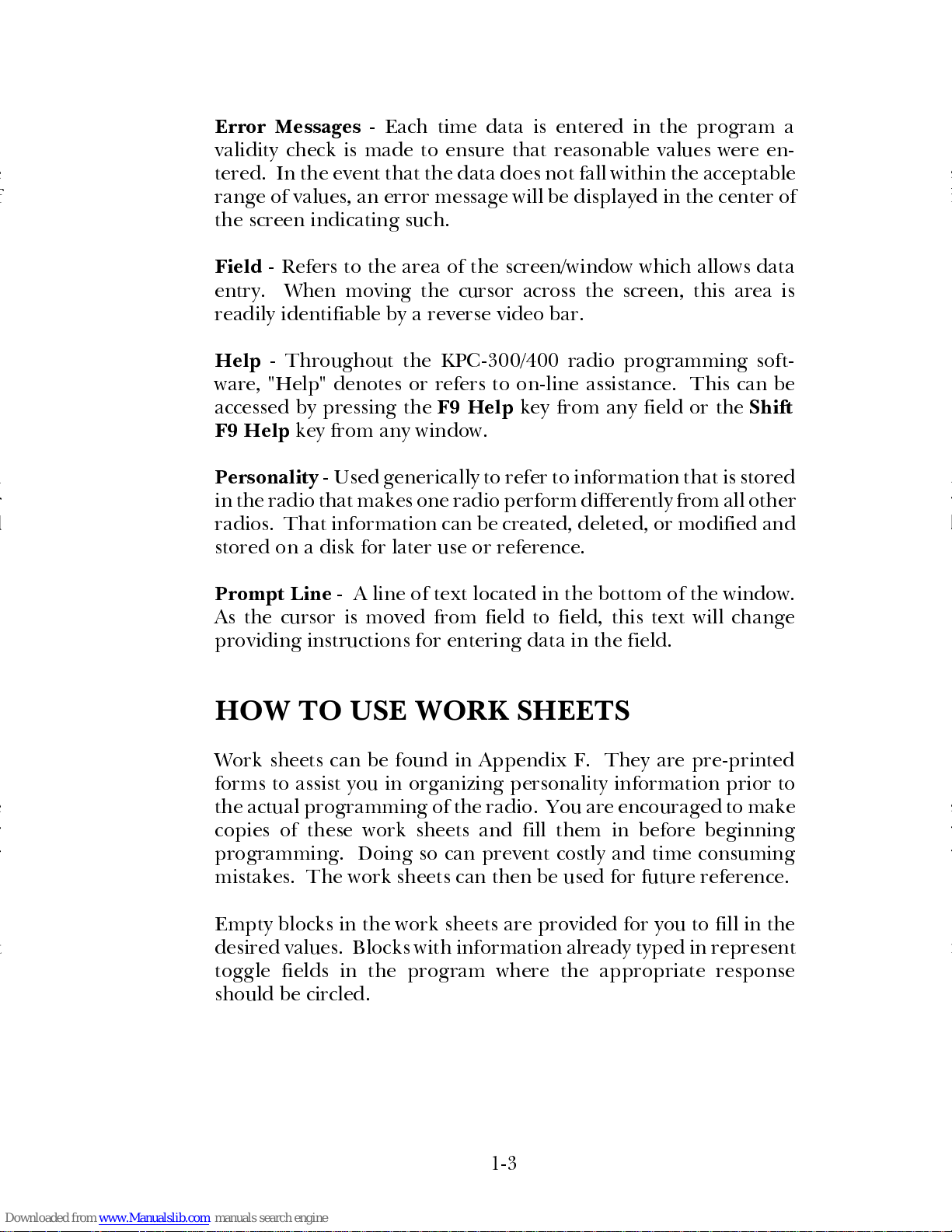
HOW SCREENS WORK
Each screen is divided into three areas: (1) screen title, (2) screen
windows, and (3) active function keys. The title tell s you where you
are in the program hierarchy. Windows provide for input of data
to the screen. Active function keys provide access to commands (or
actions) available for a particular screen. The function key com-
mands are labeled along the bottom of the screen. Only the
function keys with labels are enabled.
A window is a section of a screen that displays previously stored
information, enables programming alternatives, or accepts data
currently being entered. There may be more than one window
within a particular screen. Each window is outlined within the
screen presentation.
There are two types of windows: active and passive. The active
window is available for data entry or revision and can be identified
by its highlighted borders. The passive window is displayed but is
unavailable for program execution. If windows have overlapping
borders, the active window is presented in the foreground.
Like the screen, windows are divided into three distinct sections.
They are: (1) window title, (2) work area, and (3) prompt line. The
window title describes the function currently being performed.
The work area is the space provided fo r your input to the window.
The prompt line is printed information in the l ower portion of the
window defining in further detail the actio n to be taken in the work
area.
ÚÄEricsson GE Mobile Communications Inc.ДДДДДДДДДДДДДДДДДДДДДДДДДДДДДДДДДДДДДДД¿
³ÚÄÄÄДДДДДДДДДДДДДДДДДДДДДДДДДДДДДДДДДДДДДДДДДДДДДДДДДДДДДДДДДДДДДДДДДДДДДÄÄÄÄ¿³
(1)
³³ Directory PCS-PLUS RADIO PROGRAMMING L0-A ³³
³ÀÄÄÄДДДДДДДДДДДДДДДДДДДДДДДДДДДДДДДДДДДДДДДДДДДДДДДДДДДДДДДДДДДДДДДДДДДДДДДДДЩ³
АДДДДДДДДДДДДДДДДДДДДДДДДДДДДДДДДДДДДДДДДДДДДДДДДДДДДДДДДДДДДДДДДДДДДДДДДДДДДДДÙ
ЙНННННННННННННННННННННННННННННННННННННННННННННННННННННННННННННННННННННННННННННН»
º Current Personalities - XXX º
º X:\XXXXXXXXXXXXXXX º
º º
º º
º º
º º
(2)
º º
º º
º º
º º
º º
º º
º º
º º
º Use the cursor keys to select personality º
ИНННННННННННННННННННННННННННННННННННННННННННННННННННННННННННННННННННННННННННННН¼
(3)
F1 F2 F3 F4 F5 F6 F7 F8 F9 F10
Setup Change Utlity New Progrm Read Help Exit
Press F9 for field help, Shift F9 for window help
1-4
Page 13

This program uses a series of presentation screens to guide you
easily through the programming of a unit. There are two major
categories of data entry screens:
•
Current Personalities Screen
•
Channel Data Screen
Current Personalities Screen
- The Current Personalities Screen
lists the file names of all stored radio personaliti es presently main-
tained in this directory. From this screen you can create a new
personality (file) or make changes to existing personalities. You
then have the option of initiating one of the actions indicated by
the function keys at the bottom of the screen.
Channel Data Screen
- Data defining the radio personality is
entered into the Channel Data Screen which can be accessed from
the Current Personalities Screen by pressing function keys
F2
Change
or
F4 New
. Within this screen you can define the opera-
tional characteristics of the radio.
ÚÄEricsson GE Mobile Communications Inc.ÄÄÄДДДДДДДДДДДДДДДДДДДДДДДДДДДДДДДДДДДÄ¿
³ÚÄДДДДДДДДДДДДДДДДДДДДДДДДДДДДДДДДДДДДДДДДДДДДДДДДДДДДДДДДДДДДДДДДДДДДДДДДДДД¿³
³³ Directory PCS-PLUS RADIO PROGRAMMING L0-A ³³
³ÀÄДДДДДДДДДДДДДДДДДДДДДДДДДДДДДДДДДДДДДДДДДДДДДДДДДДДДДДДДДДДДДДДДДДДДДДДДДДДÙ³
ÀÄÄДДДДДДДДДДДДДДДДДДДДДДДДДДДДДДДДДДДДДДДДДДДДДДДДДДДДДДДДДДДДДДДДДДДДДДДДДДДÄÙ
ÉÍÍНННННННННННННННННННННННННННННННННННННННННННННННННННННННННННННННННННННННННННÍ»
º
(1)
Current Personalities - XXX º
º X:\XXXXXXXXXXXXXXX º
º º
º º
º º
º º
º
(2)
º
º º
º º
º º
º º
º º
º º
º
(3)
º
º Use the cursor keys to select personality º
ÈÍÍНННННННННННННННННННННННННННННННННННННННННННННННННННННННННННННННННННННННННННͼ
F1 F2 F3 F4 F5 F6 F7 F8 F9 F10
Setup Change Utlity New Progrm Read Help Exit
Press F9 for field help, Shift F9 for window help
1-5
Page 14
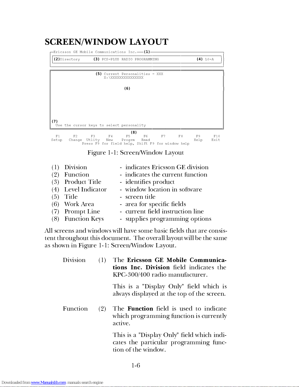
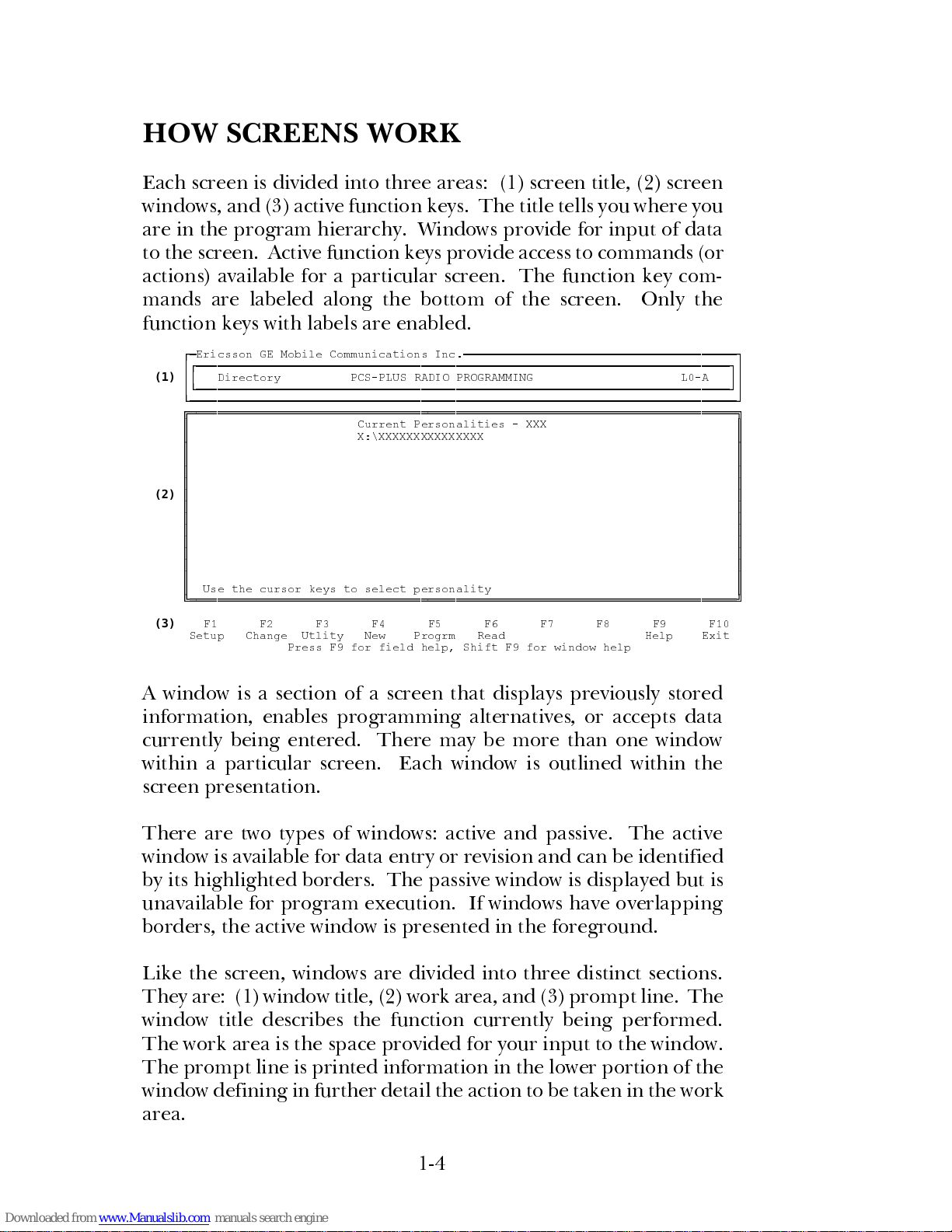
SCREEN/WINDOW LAYOUT
Figure 1-1: Screen/Window Layout
(1) Division - indicates Ericsson GE division
(2) Function - indicates the current function
(3) Product Title - identifies product
(4) Level Indicator - window location in software
(5) Title - screen title
(6) Work Area - area for specific fields
(7) Prompt Line - current field instruction line
(8) Function Keys - supplies programming options
All screens and windows will have some basic fields that are consis-
tent throughout this document. The overall lay out will be the same
as shown in Figure 1-1: Screen/Window Layout.
Division (1) The
Ericsson GE Mobile Communica-
tions Inc. Division
field indicates the
KPC-300/400 radio manufacturer.
This is a "Display Only" field which is
always displayed at the top of the screen.
Function (2) The
Function
field is used to indicate
which programming function is currently
active.
This is a "Display Only" field which indi-
cates the particular programming func-
tion of the window.
ÚÄEricsson GE Mobile Communications Inc.ÄÄÄ
(1)
ДДДДДДДДДДДДДДДДДДДДДДДДДДДДДДДДД¿
³ЪДДДДДДДДДДДДДДДДДДДДДДДДДДДДДДДДДДДДДДДДДДДДДДДДДДДДДДДДДДДДДДДДДДДДДДДДÄÄÄÄ¿³
³³
(2)
Directory
(3)
PCS-PLUS RADIO PROGRAMMING
(4)
L0-A ³³
³АДДДДДДДДДДДДДДДДДДДДДДДДДДДДДДДДДДДДДДДДДДДДДДДДДДДДДДДДДДДДДДДДДДДДДДДДДДДДЩ³
АДДДДДДДДДДДДДДДДДДДДДДДДДДДДДДДДДДДДДДДДДДДДДДДДДДДДДДДДДДДДДДДДДДДДДДДДДДДДДДЩ
ЙНННННННННННННННННННННННННННННННННННННННННННННННННННННННННННННННННННННННННННННН»
º
(5)
Current Personalities - XXX º
º X:\XXXXXXXXXXXXXXX º
º º
º º
º
(6)
º
º º
º º
º º
º º
º º
º º
º º
º º
º
(7)
º
º Use the cursor keys to select personality º
ИНННННННННННННННННННННННННННННННННННННННННННННННННННННННННННННННННННННННННННННН¼
(8)
F1 F2 F3 F4 F5 F6 F7 F8 F9 F10
Setup Change Utlity New Progrm Read Help Exit
Press F9 for field help, Shift F9 for window help
1-6
Page 15
Product
Title
(3) The
Product Title
field is used to specify
the product name and will identify which
radio the programmer is intended to be
used with.
This is a "Display Only" field which is
always displayed at the top of the screen.
Level
Indicator
(4) The
Level Indicator
field is used to indi-
cate the window location in the program.
This is a "Display Only" field which indi-
cates the current hierarchy level within
the program.
Window
Title
(5) The
Window Title
field is used to indicate
the title of a particular screen/window.
This is a "Display Only" field consistently
displayed at the top of each screen/win-
dow. This field varies to indicate which
window is being displayed.
Work Area (6) The
Work Area
is the area of a screen or
window where input fields are defined.
Each window is unique in its available
fields and each of these fields are identi-
fied in the window descriptions.
Entry to these fields will be determined by
the purpose and content of each window.
In most windows, you can move between
fields by using the arrow keys,
Home
and
End
keys,
TAB
and
<enter>
keys. Within
a field you can use the arrow keys, space
bar,
Delete-Backspace, Ctrl-Backspace
,
and alphanumeric keys. Sometimes, the
field will be "Toggle Only" where the
TAB
key is the only active key in the field and
the
<enter>
key will move you between
fields. Usually, normal cursor progres-
sion is left to right, top to bottom.
1-7
Page 16
Prompt
Line
(7) The
Prompt Line
field is used to guide
you in the proper course of action for a
particular window.
This is a "Display Only" field, displayed at
the bottom of a window. As you move
from field to field, the prompt line will
direct you for input in the particular field.
Function
Keys
(8) The
Function Keys
are used to provide
access to other options pertaining to the
window currently being displayed.
Pressing the desired function key will
cause the program to perform the indi-
cated function for that particular key. A
brief description of the operational func-
tion keys follow each window definition.
Throughout this document, the terms
screen and window are used inter-
changeably.
NOTES
1-8
Page 17
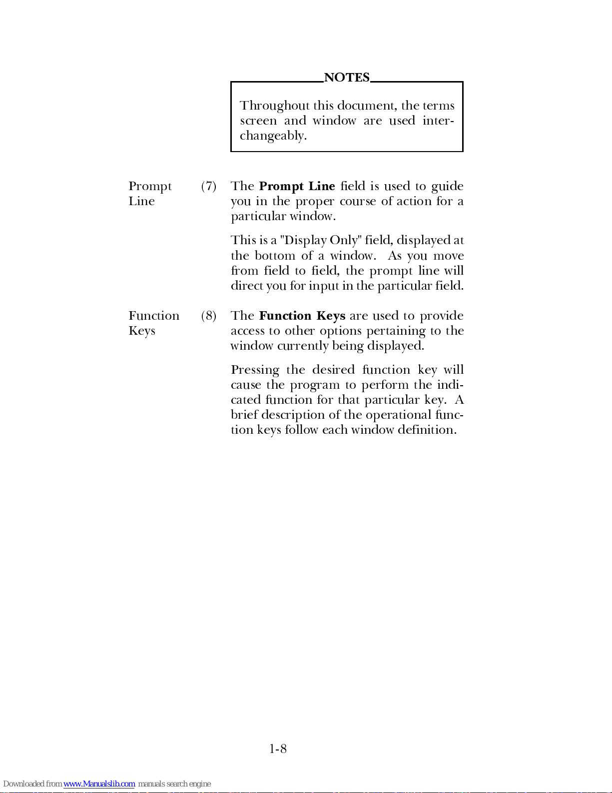
Figure 1-2: "Pop-Up" Window
(1) Function - indicates current function
(2) Main Screen - indicates the main screen
(3) "Pop-up" Window - indicates pop-up window
(4) Title - window title
(5) Work Area - area for specific field(s)
(6) Continue Prompt - continue or abort option
(7) Prompt Line - current field instruction line
(8) Function Keys - supplies programming options
Occasionally, a window will have a subordinate window that per-
forms related functions. This windows will be smaller in size and
is referred to as a "pop-up" window. Figure 1-2: "Pop-Up" Window
illustrates a "pop-up" window overlaying a main s creen. The high-
lighted, double border identifies the "pop-up" window as being
active and all data entry occurs within this window. Pressing
F10 Back
will always return you to the original window.
Main
Screen
(2) The
Main Screen
is shown as a backdrop
to the preceding "pop-up" window.
To return to this screen, you must press
the
F10 Back
function key.
"Pop-up"
Window
(3) The
"Pop-Up" Window
is shown as the
front window. This window is laid out in
the same manner as the main window.
ÚÄEricsson GE Mobile Communications Inc.ДДДДДДДДДДДДДДДДДДДДДДДДДДДДДДДДДДДДДДД¿
³ЪДДДДДДДДДДДДДДДДДДДДДДДДДДДДДДДДДДДДДДДДДДДДДДДДДДДДДДДДДДДДДДДДДДДДДДДДДДДД¿³
³³
(1)
Port PCS-PLUS RADIO PROGRAMMING L2-G ³³
³АДДДДДДДДДДДДДДДДДДДДДДДДДДДДДДДДДДДДДДДДДДДДДДДДДДДДДДДДДДДДДДДДДДДДДДДДДДДДЩ³
АДДДДДДДДДДДДДДДДДДДДДДДДДДДДДДДДДДДДДДДДДДДДДДДДДДДДДДДДДДДДДДДДДДДДДДДДДДДДДДЩ
ЪДДДДДДДДДДДДДДДДДДДДДДДДДДДДДДДДДДДДДДДДДДДДДДДДДДДДДДДДДДДДДДДДДДДДДДДДДДДДДД¿
³
(2)
Current Personalities - XXX ³
³ X:\XXXXXXXXXXXXX ³
³ ³
³ ЙННННННННННННННННННННННННННННННННННННННН» ³
³ º
(3) (4)
Communications Port Setup º ³
³ º º ³
³ º COMM Port X
(5)
º ³
³ º º ³
³ º Are you sure? Yes - Press F1
(6)
º ³
³ º No - Press F2 º ³
³ º
(7)
º ³
³ º Enter the COMM Port ID º ³
³ ИННННННННННННННННННННННННННННННННННННННН¼ ³
³ ³
³ Use the cursor keys to select personality ³
АДДДДДДДДДДДДДДДДДДДДДДДДДДДДДДДДДДДДДДДДДДДДДДДДДДДДДДДДДДДДДДДДДДДДДДДДДДДДДДЩ
F1 F2 F3 F4 F5 F6 F7 F8 F9 F10
Yes No Help Back
Press F9 for field help, Shift F9 for window help
1-9
Page 18
The title is displayed at the to p, fi elds are
in the center and where appropriate, the
prompt line is displayed in the lower left
corner.
Access is granted in this window as it is
active.
Continue
Prompt
(6) The
Continue Prompt
field allows y ou to
continue with a selection or exit.
By pressing
F1 Yes
, the field selection will
be confirmed and the programmer will
continue with the operation selected. Se-
lecting
F2 No
indicates that the operation
should not be performed and will return
you to the previous window.
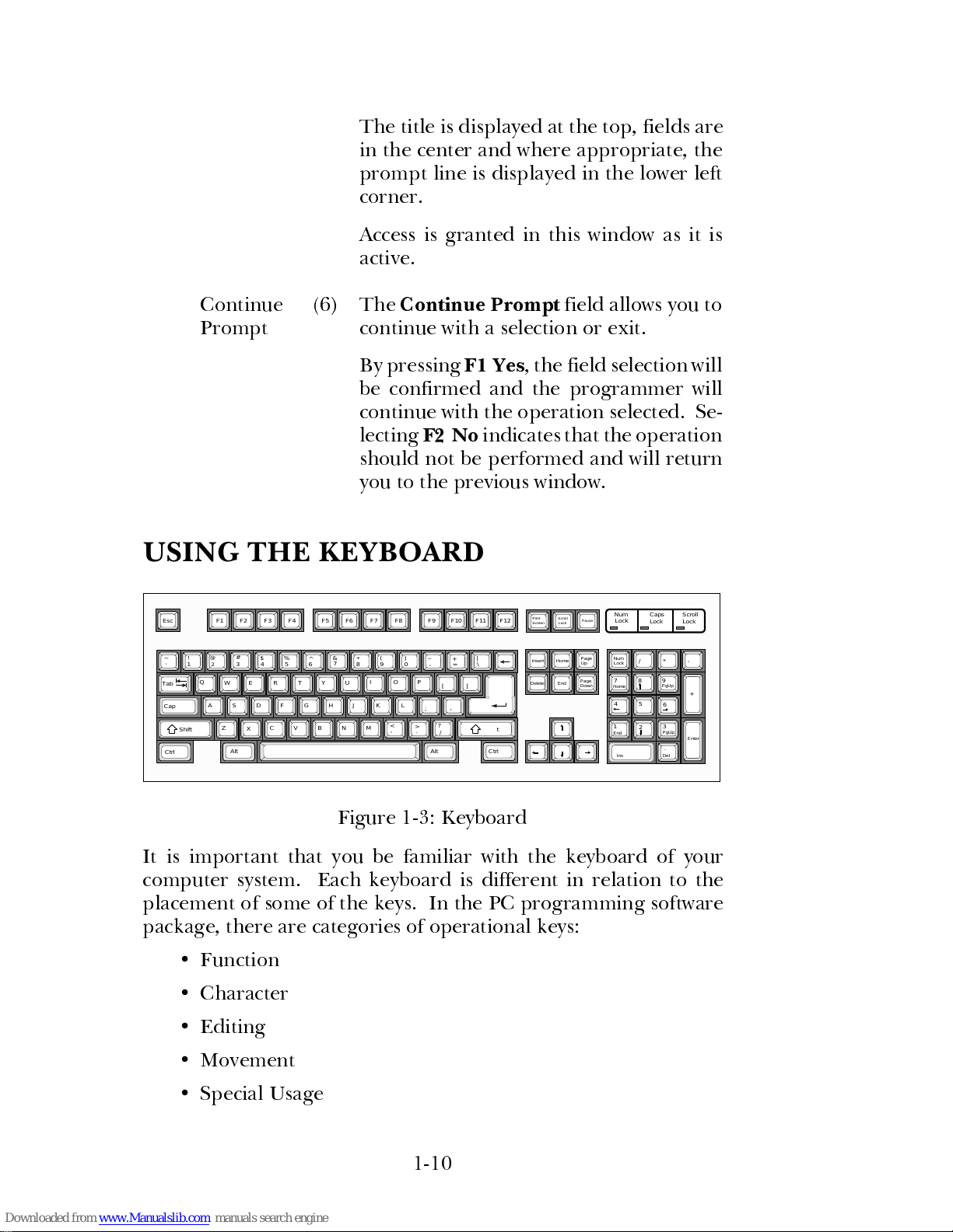
USING THE KEYBOARD
Figure 1-3: Keyboard
It is important that you be familiar with the keyboard of your
computer system. Each keyboard is different in relation to the
placement of some of the keys. In the PC programming software
package, there are categories of operational keys:
•
Function
•
Character
•
Editing
•
Movement
•
Special Usage
Esc F1 F2 F3 F4 F5 F6 F7 F8 F9 F10 F11 F12
~ !
3@4 5 6
7
9 0
8
-
= \
A
S
D
F G J KH
L
;
'
Q
EW R
T Y
U
O PI
[ ]
Z
X
C V
N
MB
,
.
/
Print
Insert
Home
Page
Delete
End
Num
/ * -
7
8
9
.
4 5
6
1
2
3
Num
Lock
Lock Lock
Caps
Scroll
Screen
Scroll
Lock
Pause
`
1
2
#
$%
^
&*()
_
+
|
Tab
CapsLock
{}
:
" Enter
Shift
Alt
Ctrl
<
>
?
Shift
Ctrl
Alt
Up
Page
Down
Lock
Home
PgUp
PgUp
End
Ins
Enter
Del
+
1-10
Page 19
The following sections give an o verview of which keys are included
in these categories and what their uses are. However, in some
screens, such as the Current Personalities Screen, only the use of
cursor keys is allowed because selection operation is all that is
needed.
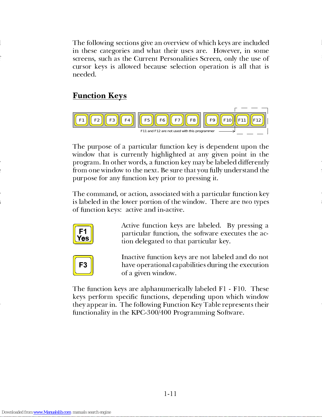
Function Keys
The purpose of a particular function key is dependent upon the
window that is currently highlighted at any given point in the
program. In other words, a function key may be labeled differently
from one window to the next. Be sure that you fully understand the
purpose for any function key prior to pressing it.
The command, or action, associated with a particular function key
is labeled in the lower portion of the window. There are two types
of function keys: active and in-active.
Active function keys are labeled. By pressing a
particular function, the software executes the ac-
tion delegated to that particular key.
Inactive function keys are not labeled and do not
have operational capabilities during the execution
of a given window.
The function keys are alphanumerically labeled F1 - F10. These
keys perform specific functions, depending upon which window
they appear in. The following Function Key Table represents their
functionality in the KPC-300/400 Prog ramming Software.
F1 F5 F9F2 F3 F4 F6 F7 F8 F10 F11 F12
F11 and F12 are not used with this programmer
1-11
Page 20
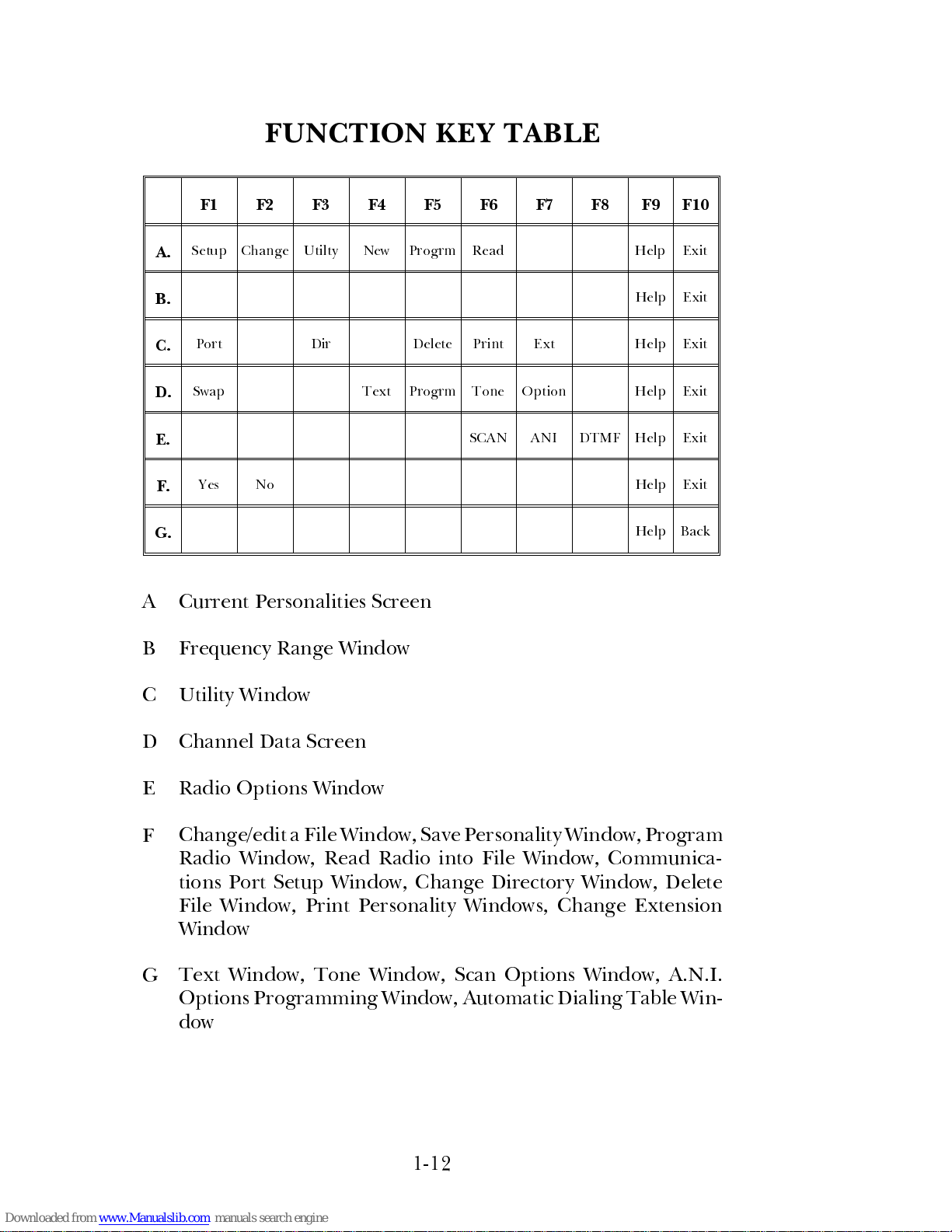
FUNCTION KEY TABLE
F1 F2 F3 F4 F5 F6 F7 F8 F9 F10
A.
Setup Change Utilty New Progrm Read Help Exit
B.
Help Exit
C.
Port Dir Delete Print Ext Help Exit
D.
Swap Text Progrm Tone Option Help Exit
E.
SCAN ANI DTMF Help Exit
F.
Yes No Help Exit
G.
Help Back
A
Current Personalities Screen
B
Frequency Range Window
C
Utility Window
D
Channel Data Screen
E
Radio Options Window
F
Change/edit a File Window, Save Personality Window, Program
Radio Window, Read Radio into File Window, Communica-
tions Port Setup Window, Change Directory Window, Delete
File Window, Print Personality Windows, Change Extension
Window
G
Text Window, Tone Window, Scan Options Window, A.N.I.
Options Programming Window, Automatic Dialing Table Win-
dow
1-12
Page 21
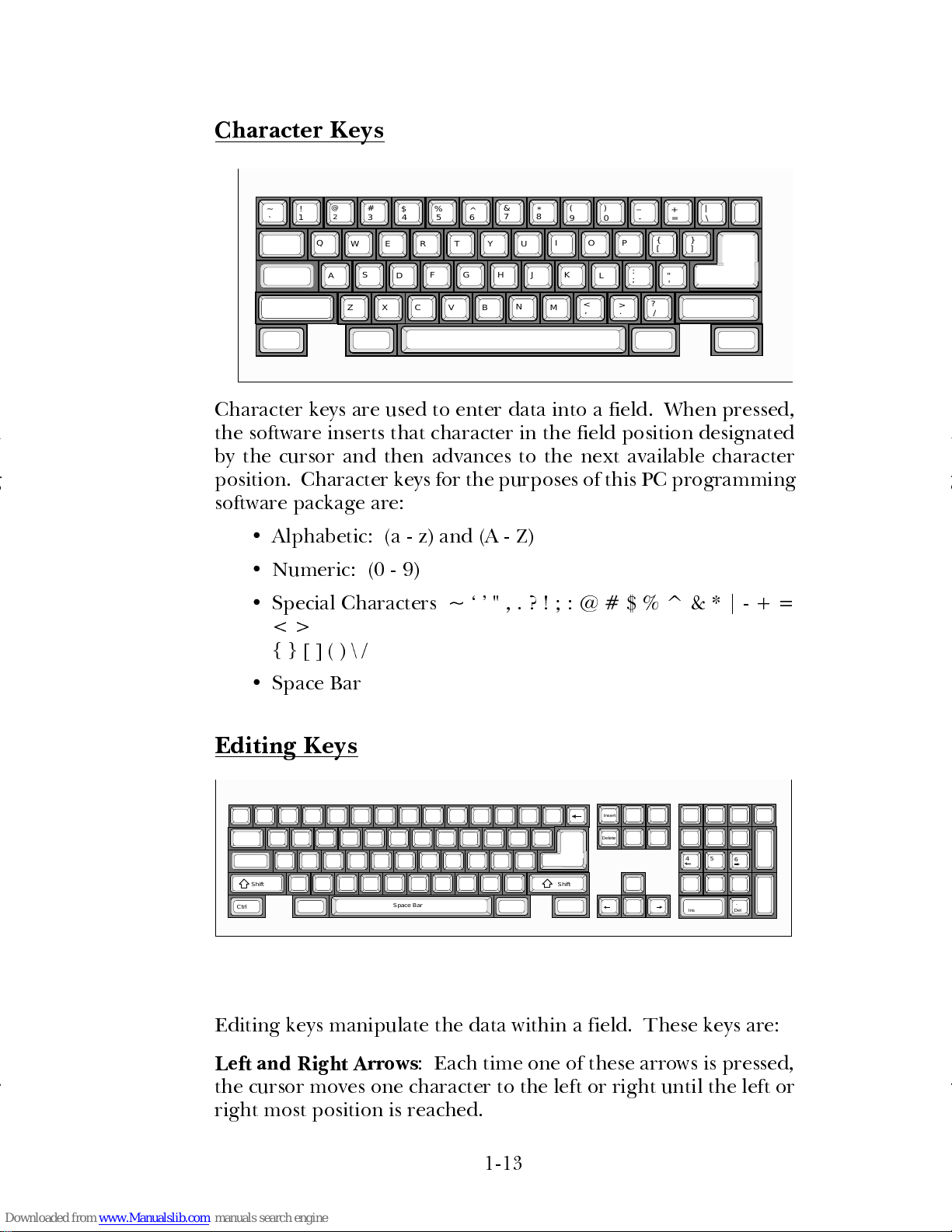
Character Keys
Character keys are used to enter data into a field. When pressed,
the software inserts that character in the field position designated
by the cursor and then advances to the next available character
position. Character keys for the purposes of this PC programming
software package are:
•
Alphabetic: (a - z) and (A - Z)
•
Numeric: (0 - 9)
•
Special Characters ~ " , . ? ! ; : @ # $ % ^ & * | - + =
< >
{ } [ ] ( ) \ /
•
Space Bar
Editing Keys
Editing keys manipulate the data within a field. These keys are:
Left and Right Arrows
: Each time one of these arrows is pressed,
the cursor moves one character to the left or right until the left or
right most position is reached.
Insert
Delete
.
4 5
6
ShiftShift
Ctrl
Ins
Del
Space Bar
~ !
3@4 5 6
7
9 0
8
-
= \
A
S
D
F G J KH
L
;
'
Q
EW R
T Y
U
O PI
[ ]
Z
X
C V
N
MB
,
.
/
`
1
2
#
$%
^
&
*
()
_
+
|
{}
:
"
<
>
?
1-13
Page 22
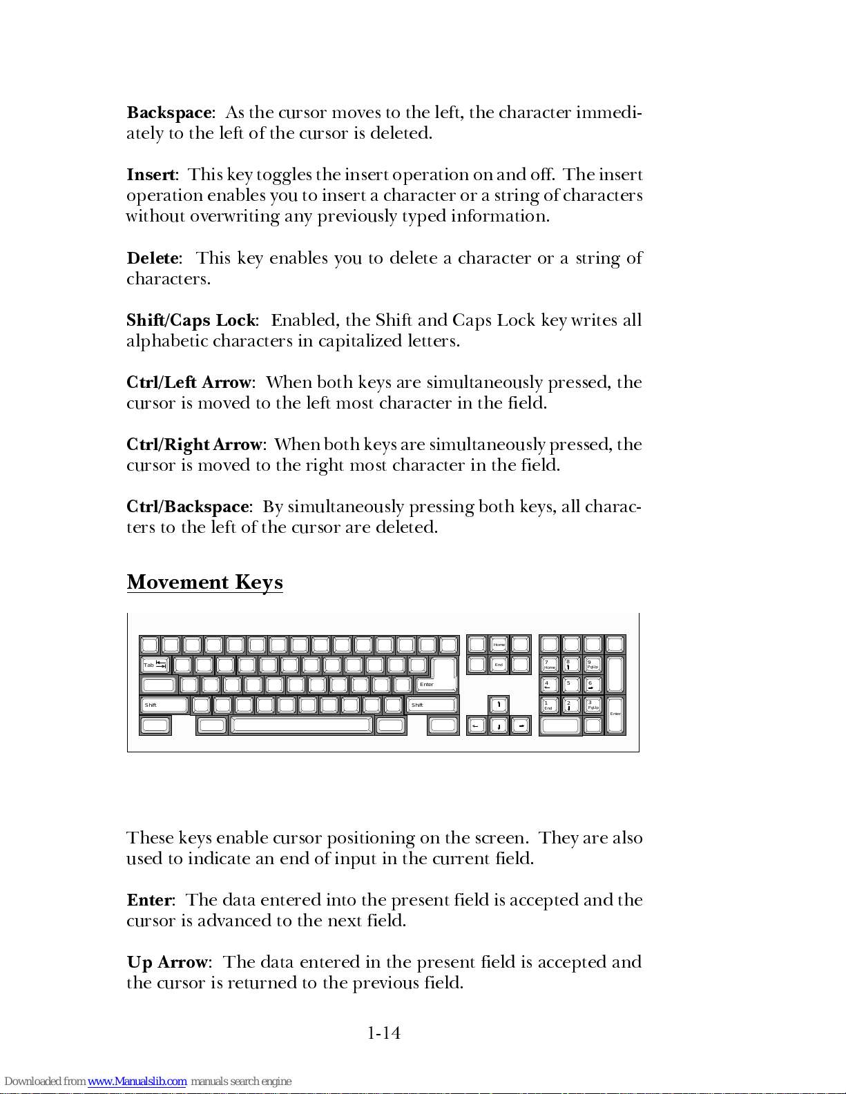
Backspace
: As the cursor moves to the left, the character immedi-
ately to the left of the cursor is deleted.
Insert
: This key toggles the insert operation on and off. The insert
operation enables you to insert a character or a string of characters
without overwriting any previously typed information.
Delete
: This key enables you to delete a character or a string of
characters.
Shift/Caps Lock
: Enabled, the Shift and Caps Lock key writes all
alphabetic characters in capitalized letters.
Ctrl/Left Arrow
: When both keys are simultaneously pressed, the
cursor is moved to the left most character in the field.
Ctrl/Right Arrow
: When both keys are simultaneously pressed, the
cursor is moved to the right most character in the field.
Ctrl/Backspace
: By simultaneously pressing both keys, all charac-
ters to the left of the cursor are deleted.
Movement Keys
These keys enable cursor positioning o n the screen. They are also
used to indicate an end of input in the current field.
Enter
: The data entered into the present field is accepted and the
cursor is advanced to the next field.
Up Arrow
: The data entered in the present field is accepted and
the cursor is returned to the previo us fi eld.
Home
End
7
8
9
4 5
6
1
2
3
Tab
Enter
Home
PgUp
PgUp
End
Enter
Shift Shift
1-14
Page 23
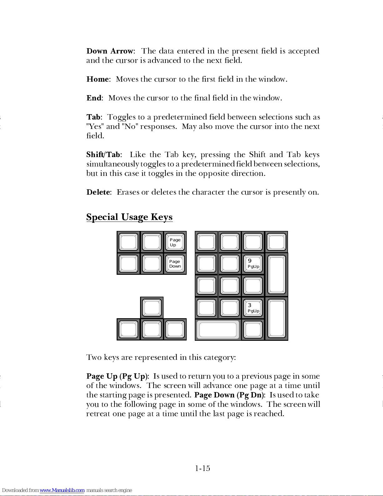
Down Arrow
: The data entered in the present field is accepted
and the cursor is advanced to the next field.
Home
: Moves the cursor to the first field in the window.
End
: Moves the cursor to the final field in the window.
Tab
: Toggles to a predetermined field between selections such as
"Yes" and "No" responses. May also move the cursor into the next
field.
Shift/Tab
: Like the Tab key, pressing the Shift and Tab keys
simultaneously toggles to a predetermined field between s elections,
but in this case it toggles in the opposite direction.
Delete
: Erases or deletes the character the cursor is presently on.
Special Usage Keys
Two keys are represented in this category:
Page Up (Pg Up)
: Is used to return you to a previous page in some
of the windows. The screen will advance one page at a time until
the starting page is presented.
Page Down (Pg Dn)
: Is used to take
you to the following page in some of the windo ws. The screen will
retreat one page at a time until the last page is reached.
Page
3
Up
Page
Down
PgUp
PgUp
9
1-15
Page 24
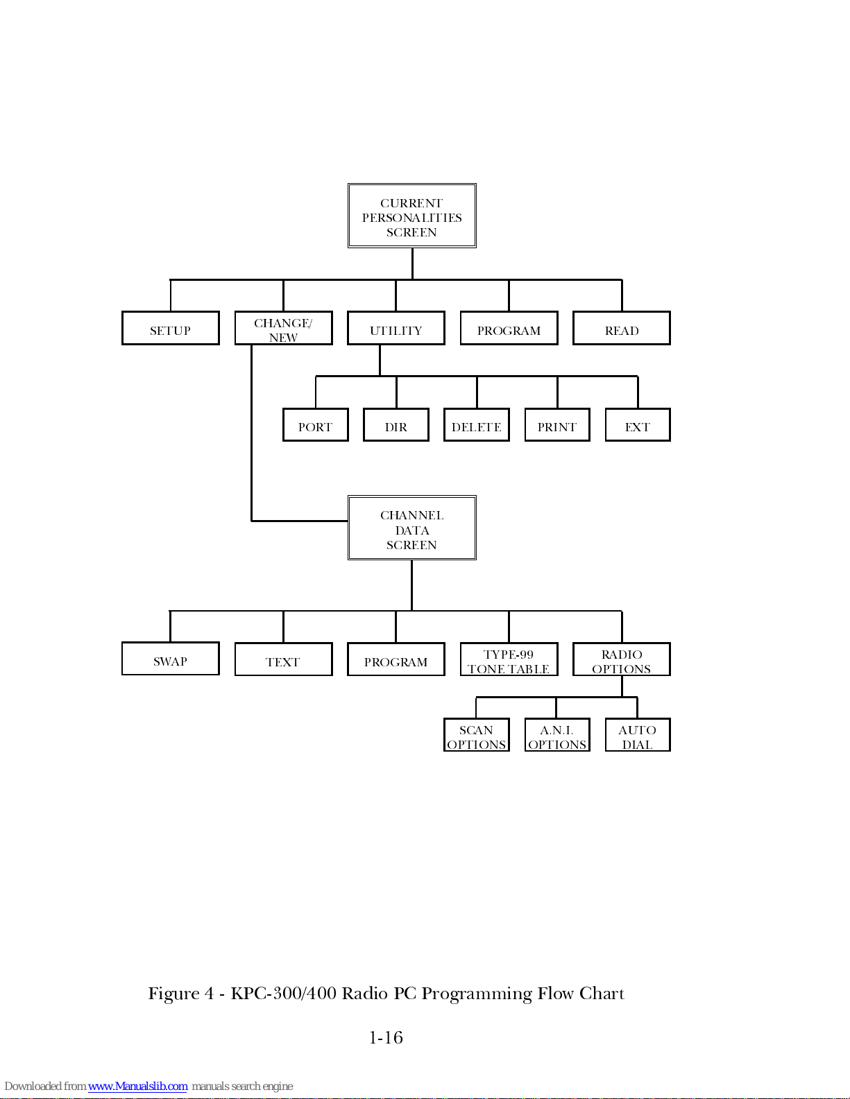
Figure 4 - KPC-300/400 Radio PC P rogramming Flow Chart
CHANNEL
DATA
SCREEN
CURRENT
PERSONALITIES
SCREEN
RADIO
OPTIONS
PROGRAM
TYPE-99
TONE TABLE
PRINT
TEXT
SETUP
AUTO
DIAL
A.N.I.
OPTIONS
SCAN
OPTIONS
EXT
UTILITY PROGRAM
CHANGE/
NEW
READ
DELETEDIRPORT
SWAP
1-16
Page 25
CHAPTER 2
INSTALLATION
UNPACKING
Upon unpacking this package you should be sure you have received
the following:
•
KPC-300/400 Radio PC Programming Software (AE/LZT
123 1895 R1A), to include:
One 3-1/2 inch disk ette (labeled "Program Disk").
PC PROGRAMMING SOFTWARE
REQUIREMENTS
The following hardware and software is required to program a
KPC-300/400 Radio:
A. IBM PC XT, AT, or any true compatible with MS-DOS version
3.0 or later, and having the following minimum configuration:
1. Two Disk Drives; a single 3 1/2" floppy with a fixed (hard)
disk drive system.
2. 640K Internal RAM.
3. Serial Port.
4. Parallel Port (recommended) for connection to a printer.
B. Serial Pr ogramming Interface Module (TQ-3370) and RS -232
Cable (part #19B235027P1).
C. Radio Programming Cable (TQ-3336).
D. KPC-300/400 Radio Programming Software (CXC 112 1286
R1A).
E. Printer (optional, but recommended).
2-1
Page 26
DISKETTE HANDLING
While working with your disk ettes, consider the following handling
procedur es:
•
Always store yo ur diskettes in their envelope.
•
Insert diskettes into the drive carefully.
•
Use only felt tipped pens to write on diskette labels.
•
Store your diskettes at a comfortable room temperature.
•
Do not touch the recording surface of the diskette.
•
Do not bend the diskettes.
•
Do not allow any form of liquid to come in contact with the
diskette surface.
•
Keep disk ettes away fr om magnetic force fiel ds as found in
magnets and electronic equipment.
If you follow these simple guidelines you will receive long service
from your diskettes.
MAKING BACKUPS
The KPC-300/400 radio programming softwar e i s pr ov ided to yo u
on a 3-1/2 inch diskette. This diskette is sensitive and fragile and
should be handled with care and stored in a secure area.
Upon receipt of your diskette, copy the original PC Programming
Software diskette to another diskette or a fixed disk and store the
original in a safe place. This ensures the availability of an accurate
program should a copy fail during program application.
It is important to use the "DISKCOPY" command when
making a backup and
not the "COPY" or "XCOPY" com-
mands. Each diskette contains a volume label that is re-
quired for the installation process. "COPY" and "XCOPY"
do not copy volume labels, so please refrain from using
these commands.
NOTE
2-2
Page 27
SYSTEM HOOK-UP
Connect all peripheral equipment to your computer prior to con-
figuring the PC Pro gramming Software items. Remember to r efer
to the operating manuals of each device for correct installation
procedures.
If your system is already established, check to see that you have all
the equipment necessary to execute the program. Isolate all cables
connecting computer to devices to prevent tangling, interference,
and damage.
Step One:
Refer to Figure 2-1, Pr og ramming System Hook-up, and then lo ok
at your computer to locate a serial port. This port will usually be
located at the rear of the computer. However, since this is depend-
ent upon the design of your computer refer to the computer
operators manual for directions.
The IBM PC XT/AT systems support up to two serial ports. Ther e
are two physical standards for the serial port configurations of
personal computers. The first standard is a 25 pin RS-23 2 o utput
that has a DB-25 male connector at the computer. The other
standard is a DB-9 male connector at the computer ( used on the
IBM-AT and many portable lap-top computers). The PC Interface
Module, like most data com munications equipment, uses a stand-
ard RS-232, DB -25, female connector. If your computer uses a
DB-9 connector, you will need to purchase a DB-9/DB-25 adapter
cable from your local computer dealer.
Please note at this point that the KPC-300/400 radio PC pr o gram-
ming software only communicates with the radi o through the cable
connected to the serial port designated as COM1 or COM2. Your
computer references will assist you in determining which serial port
is which. Once located, examine the keyed plug on the RS-232
cable for the correct keyed end and insert it carefully into the
appropriate serial port on the computer.
2-3
Page 28
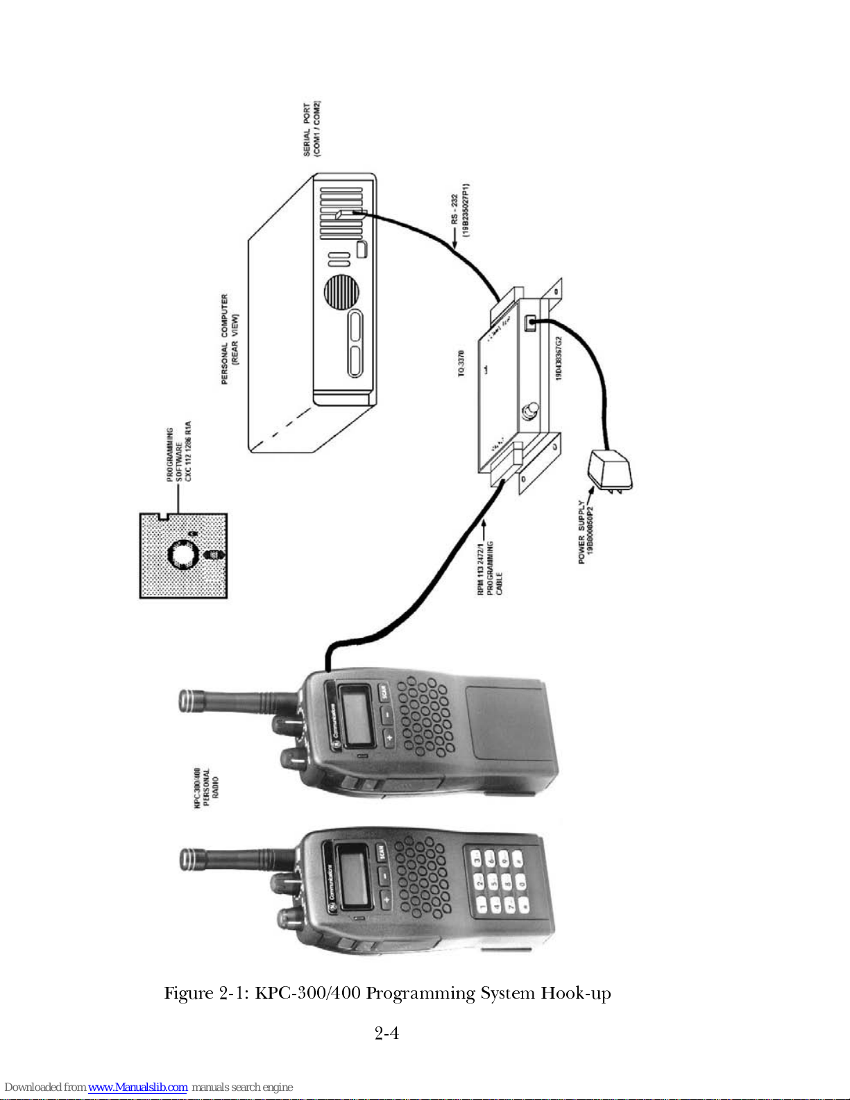
Figure 2-1: KPC-300/400 Programming System Hook-up
2-4
Page 29
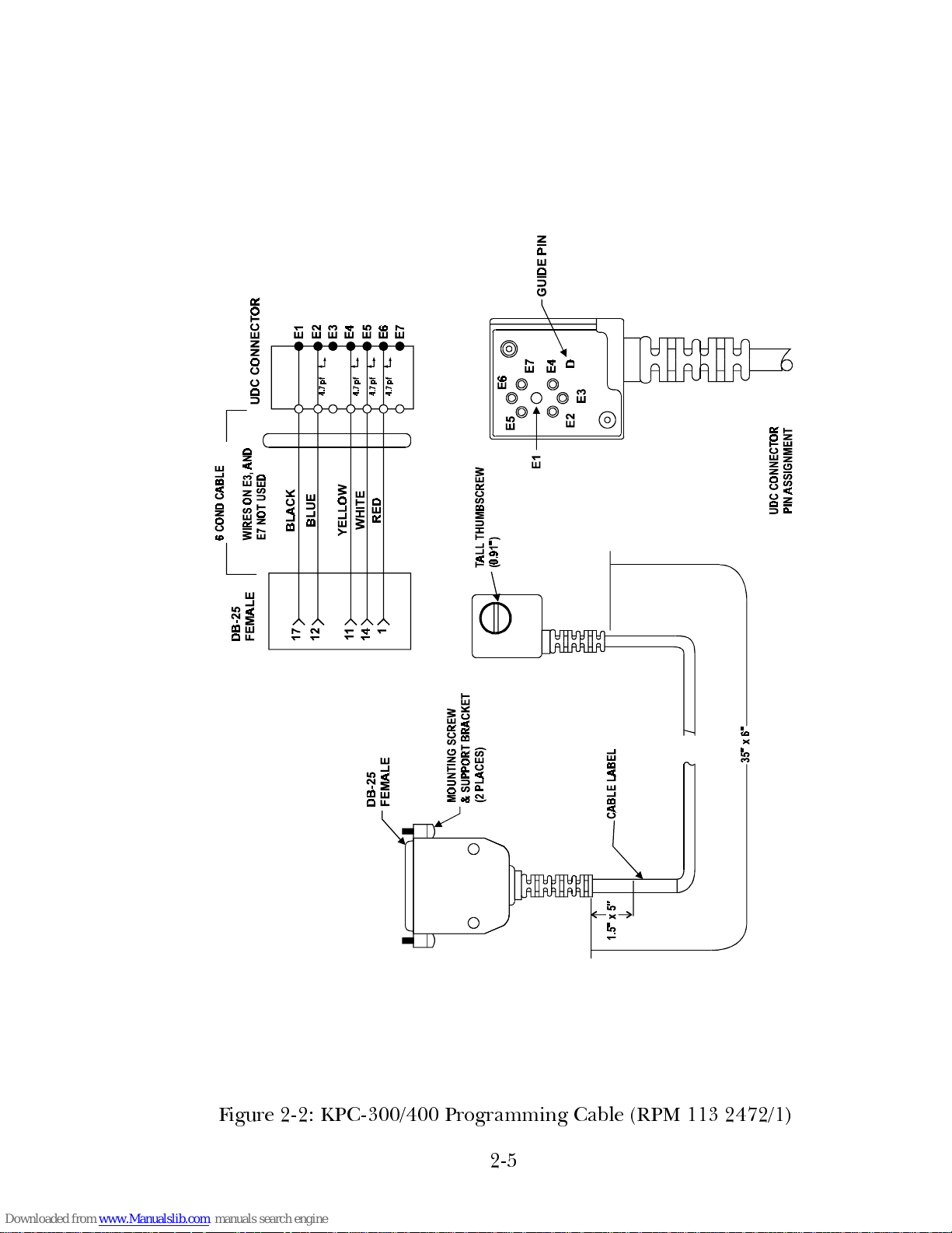
Figure 2-2: KPC-300/4 00 Programming Cable (RPM 113 2472/1)
2-5
Page 30
Step Two:
The other end of the RS-232 cable should now be connected into
the computer receptacle on the PC Interface Module. Check
carefully to ensur e that plugs are fully seated in the receptacle and,
if retaining s crews ar e included, that they ar e carefully tightened to
firmly hold the plug in place. Should the plug not seat correctly to
its receptacle, r emove the plug and e xamine the pins to determine
if the proper plug was inserted and to determine if pins are al igned
and undamaged. Damaged pins and broken connections wil l cause
the PC programming softwar e to fai l.
Step Three:
P ositi on the KPC-300/400 radio in a convenient place i n your work
area. Connect the PC Programming Cable as depicted in Figure
2-1. The Pr ogramming Cable is inserted into the r eceptacle on the
back of the unit. Again you should ensure that the plug is fully
seated in its receptacle. The cover must be removed before con-
necting the cable.
LOADING THE SOFTWARE
The programming softwar e can be instal led on a fix ed drive or run
from a floppy diskette in a floppy drive configuration.
Software Installat ion
This section is for hard drive users only. If floppy drives are being
used, skip this section and go on to the Prog ram Entry section.
3-1/2" Diskette:
When using the 3-1/2 inch diskette, the software installation is
initiated by inserting the Pro gram Disk in drive A and typing:
INST ALL <enter>
The Installation Screen will appear next. Enter the target drive to
indicate which disk drive the program will be loaded to. (It must
be a hard drive).
2-6
Page 31

Press
F1 Begin
.
This will cause the program to copy the files from the distribution
diskette to yo ur har d drive.
Program Entry
To help you manage your programming software, a directory
structure, or filing system, has been created for your programs.
This filing system is created whenever any PC programming soft-
ware is installed on your hard disk and also applies to floppy disk
users.
When the KPC-300/400 radio PC programming software is in-
stalled, a directory structure consisting of four subdirectories is
created. This structure is r epresented graphically as follows:
\ (ROOT) GE
CARD RADIO
HELP
The first directory created is the GE directory; the main directory
under which all programming software will be stored. This direc-
tory will contain a batch file that is used to invoke the pr ogramming
software. W ithin this directory , the CARD dir ectory is created. This
directory stores all of the executable programs required for the
programming of the radio.
The PC programming softwar e is distributed with a number of help
files that reside in the Help dir ectory and are used by the program
whenever
F9 Help
or
Shift F9 Help
is pressed. These files ar e only
required to support the on-line help facility and may be removed
if on-line help is not required. The final directory created is the
Radio directory. The purpose of this directory is to hold the
personalities created during program operation.
Directories can be used very effectively in or ganizing your program-
ming personalities. It is highly r ecommended that you famil iarize
yourself with dir ectories. Refer to your DOS Users Manual for more
information.
2-7
Page 32

Hard Disk:
Once you have completed the installation procedure, the following
steps may be taken to access the KPC-300/400 radio PC program-
ming software:
Type: C:
<enter>
to ensure that the current drive is C:
(The drive indicated here should be
the letter of the drive specified as the
target drive during program installa-
tion.)
Type:
cd GE <enter>
to change directories to the GE direc-
tory
Type:
CARD <enter>
to bring up the programming softwar e
application
The KPC-300/400 Radio P rogramming Softwar e is now loaded into
memory and a copyright screen appears briefly before the Current
Personalities Scr een is displayed.
Dual Floppy:
When the programming software is used in a dual floppy config-
ured computer , sev eral additional steps are r equired before lo ading
the software.
3-1/2" Diskette:
1. I nsert the DOS disk in Drive A and turn on or "boot up" the
computer.
2. Place a blank formatted disk in Drive B.
The formatted disk in Drive B will become your data disk
on which you will store the personal ity information and data
for the radio.
NOTE
2-8
Page 33

3. Replace the DOS disk in Drive A with the programming soft-
ware disk labeled Program Disk.
4. At the prompt, type:
A: <enter>
cd\GE\CARD <enter>
CARD <enter>
This will run the batch file which executes the main program
and switches the current directory to Drive B to store and edit
the personality files.
2-9
Page 34

This page intentionall y bl ank
2-10
Page 35

CHAPTER 3
GETTING STARTED
The following brief tutorial is designed to give you an under-
standing of how the program operates and to also give you some
hands on experience before you begin actual programming. We
encourage you to explore the program and view all screens and
windows during this tutorial. If you need on-li ne ass is tance at any
point in this program, press
F9 Help
and a help message for the
field you are in will appear.
Before you start the tutorial, refer to your hardware set up and
ensure that the radio has been set up according to the installation
procedures in Chapter 2. Once installation has been completed,
follow the Program Entry steps. A fter you type
CARD
and press
<enter>
, a brief copyright screen will appear followed by the
Current Personalities Screen. You are now ready to begin this
tutorial.
When programming a radio, it is advi sed that you first fi ll out work
sheets (located in Appendix F of this manual). These work sheets
will assist you while you are programming the radio and serve as
reference material should questions arise during radio operation.
Work sheets for this tutorial have already been filled out and
precede the window you will be working in.
From the Current Personalities Scr een, press
F1 Setup
.
This will take you into the Setup portion of the program. Before
you can create a personality , the f requency range for the personality
you are creating must be defined.
3-1
Page 36

Work Sheet A - Setup
FREQUENCY RANGE:
VHF -
UHF -
136 - 153
403 - 440
150 - 174
440 - 470 470 - 512
In the F requency Range Windo w , position y our cursor on UHF
range
403 - 440
and press
F10 Back
.
This will set the band split.
Press
F10 Back
.
This will confirm all Setup settings and return you to the Current
Personalities Scr een.
In the Current Personalities Screen, select the
F4 New
key.
Now you are ready to begin defining the personality you are
creating. Reference the Channel Data Work Sheet, and enter the
information in the program.
CHANNEL 1:
Type
405.0125
in the Tx Frequency field and press
<enter>
.
Work Sheet B - Channel Data
Part 1
PERSONALITY
PERS1
CH T X. FREQ. RX. FREQ. TX CHAN.
GUARD
RX CHAN.
GUARD
1 405.0125 405.0125 67.0 67.0
2 412.0000 412.0250 073 073
3-2
Page 37

Work Sheet B - Channel Data
Part 2
PERSONALITY
PERS1
Notice that the T ransmit F requency is automatically copied into the
Receive Frequency fi eld.
Press
<enter>
to advance to the Tx Chan Guard field. Type
67.0
and press
<enter>
.
Notice that the Transmit Channel Guard is automatically copied
into the Receive Chan Guard field.
Press
<enter>
to advance to the Pw field.
No entry is needed in this field as the default entry is the chosen
selection.
Press
<enter>
to advance to the STE field. Use the
TAB
key
as a toggle switch to toggle the field to
Yes
. Press
<enter>
.
No entry is needed in the DTMF field as the default entry is the
chosen selection.
Press
<enter>
to advance to the ANI field.
No entry is needed in the ANI f ield as the default entry is the chosen
selection .
Press
<enter>
to advance to the Bsy field.
CHANNEL OPTIONS TYPE-99 DECODES
CH POWER STE DTMF ANI BUSY TABLE INDIV GROUP SUPER QUICK
1
Hi
Lo
Yes
No
Yes
No
Yes
No
Yes
No
1
2
Yes
No
Yes
No
Yes
No
Yes
No
2
Hi
Lo
Yes
No
Yes
No
Yes
No
Yes
No
1
2
Yes
No
Yes
No
Yes
No
Yes
No
3-3
Page 38

No entry is needed in the BSY fiel d as the default entry is the chosen
selection .
Press
<enter>
to advance to the Tb field.
The cursor should now be on the Tb field o f Channel 1. This is the
first field in the Type-99 Decode area. Before you can define
Type-99 Decode fields, reference the Type-99 Tone Table Work
Sheet.
From the Channel Data Screen, press
F6 Tone
to enter the
Type-99 Tone Table Window.
Work Sheet C - Type-99 Tone Table
PERSONALITY
PERS1
POWER UP MODE:
Selective Monitor
TABLE 1 TABLE 2
GE FORMAT?
Yes No Yes No
TONE A
TONE B
TONE C
TONE D
For GE Format Table 1, select
Yes
and press
<enter>
to advance
to the Table 2 field. Select No and press
<enter>
twice to advance
to the Tone A field in Table 2.
Type
500.3
and press
<enter>
.
Type
488.5
in the Tone B Table 1 field and press
<enter>
.
Type
510.50
in the Tone B Table 2 field.
488.5
500.3 Hz
510.5 Hz
3-4
Page 39

You can now go back into the Channel Data Screen and def ine the
Type-99 Decode fields.
Press
F10 Back
.
Using the
TAB
key as a to gg le s witch, tog gle the Tb field to 2.
Press
<enter>
to advance to the Ind field. Toggle the field to
Yes
. Press
<enter>
.
The work sheet indicates that the Grp field should be set to
No
which is the default for that field.
Press
<enter>
again.
The cursor advances past the Spr field to the Qck field.
Toggle the Qck field to
Yes
and press
<enter>
.
You should now be on the Tx Frequency field for Channel 2.
CHANNEL 2:
In the Tx Frequency field, type
412.0000
press
<enter>
.
Again the Transmit Frequency is automatically copied into the
Receive Frequency field. However, for channel 2, you want the
Receive Frequency to be different from the Transmit Frequency.
Press the
Ctrl-Backspace
keys together to clear the entry . Type
412.0250
and press
<enter>
.
In the Tx Chan Guard field type
073
and press
<enter>
.
The T ransmit Channel Guard field is auto matically copied into the
Receive Chan Guard field.
Press
<enter>
to advance to the Pw field. The default is the
required setting for this field, so press
<enter>
again to
advance to the DTMF field. The STE field is skipped, because
of the Channel Guard Frequency values being Tone Frequen-
cies.
3-5
Page 40

No further information needs to be entered since your work sheet
indicates the remaining fields ar e to be set according to their default
values.
Now that all the channel data information has been enter ed for this
personality, you should save your selections and name the person-
ality.
To do so, press
F10 Back
. The Save Personality Window will
appear. Press
Ctrl-Backspace
simultaneously to clear out the
file name field. Type
PERS1
.
Your newly created personality has now been named and is ready
to be saved to disk.
Press
F1 Yes
.
The new personality will be sav ed to disk and the personal ity name
will appear in the Current Personalities Screen.
The next step is to program the pers onal ity i nto the radio.
F rom the Current Personalities Screen, position y our cursor on
PERS1
. Select
F5 Progrm
.
The Program Radio Windo w will appear with
PERS1
as the selected
file name.
Select
F1 Yes
.
Do not attempt the program sequence without ensuring
that the Serial Programming Interface Module is properly
connected. F ailur e to attach the Serial Pr ogramming Inter-
face Module prior to a program or read operation may
result in system lock-up. Should this occur , r efer to Chapter
6 of this manual.
NOTE
3-6
Page 41

A message will appear on the screen indicating that the personality
is being downloaded into the radio. The program operation is
finished when the program window disappears fr om the screen and
you are returned to the Curr ent Personalities Screen.
You have now completed th e tutorial. You can delete the person-
ality if you like or keep it in your program for future reference.
To delete the personality, position your cursor on
PERS1
.
Select
F3 Utilty
, press
F5 Delete
, press
F1 Yes
.
A message window will appear asking yo u to pr ess Y if you ar e sur e
you want to delete the personality, or N to abort the operation.
Remember that deleting a personality will remove it permanently
from the data base.
Press Y to delete.
The selected personality will be deleted from the disk and will no
longer appear in the Current Personalities Screen.
3-7
Page 42

This page intentionally left blank
3-8
Page 43

CHAPTER 4
RUNNING THE PROGRAM
INITIALIZATION
Depending on its manufacturer, your personal computer will have
certain unique operating characteristics which make it different
from other computers of similar capability . For example, file names
and file ex tensi ons must confo rm to the r equirements of your disk
operating system. W e, therefor e, recommend that you become fully
conversant with your computers disk operating system and its
operating manual prior to beginning this program.
When you turn on your personal computer, it begins an initializa-
tion routine which every system must go through to prepare for
operation. During initialization, the MS-DOS program is loaded
into memory . MS-DOS is the interpreter between keyboar d actions
and the capabilities of the PC programming software.
Once the PC is initialized and the DOS prompt is displayed, type:
cd\GE <enter>
CARD <enter>
After a brief introductory screen the Current Personalities Screen
will appear.
4-1
Page 44

Figure 4-1: Current Personalities Screen
(1) Function - indicates directory function
(2) Screen Title - current personalities screen
(3) Default Extension - designated default ex tension
(4) Current Drive - desi gnated drive
(5) Current Directory - designated directory name
(6) Personality Area - personalities in current directory
(7) Prompt Line - current field instruction line
The Current Personalities Scr een, shown in Figur e 4-1, is the main
screen for the KPC-300/400 Programming Software. From this
screen, you will be able to create perso nalities , program personali-
ties into a radio, and read personaliti es out of a radio. To access a
personality, m ove the cursor (reverse video bar) across the screen
using the arrow k eys. Ther e is room available for up to 70 person-
alities on the screen. If you completed the tutorial and did not
delete the files you created, one or two personality file names will
already be display ed. Once the screen is full, additio nal personali-
ties can be accessed by pressing the Pg Dn key.
ÚÄEricsson GE Mobile Communications Inc.ДДДДДДДДДДДДДДДДДДДДДДДДДДДДДДДДДДДДДДД¿
³ЪДДДДДДДДДДДДДДДДДДДДДДДДДДДДДДДДДДДДДДДДДДДДДДДДДДДДДДДДДДДДДДДДДДДДДДДДДДДД¿³
³³
(1)
Directory CARDINAL RADIO PROGRAMMING L0-A ³³
³АДДДДДДДДДДДДДДДДДДДДДДДДДДДДДДДДДДДДДДДДДДДДДДДДДДДДДДДДДДДДДДДДДДДДДДДДДДДДЩ³
АДДДДДДДДДДДДДДДДДДДДДДДДДДДДДДДДДДДДДДДДДДДДДДДДДДДДДДДДДДДДДДДДДДДДДДДДДДДДДДЩ
ЙНННННННННННННННННННННННННННННННННННННННННННННННННННННННННННННННННННННННННННННН»
º
(2)
Current Personalities - CAR
(3)
º
º
(4)
C:\GE\CARD\RADIO
(5)
º
º º
º º
º º
º
(6)
º
º º
º º
º º
º º
º º
º º
º º
º
(7)
º
º Use the cursor keys to select personality º
ИНННННННННННННННННННННННННННННННННННННННННННННННННННННННННННННННННННННННННННННН¼
F1 F2 F3 F4 F5 F6 F7 F8 F9 F10
Setup Change Utlity New Progrm Read Help Exit
Press F9 for field help, Shift F9 for window help
4-2
Page 45

From the Current Personalities Scr een, function key options are:
F1 - Setup
Select this option if you want to:
Select personality creation defaults.
F2 - Change
Select this option if you want to:
Change or edit an existing personality.
F3 - Utilty
Select this option if you want to:
Change the communication port entry , change the
directory, delete a personality, print a personality,
or change the extension.
F4 - New
Select this option if you want to:
Create a new personality.
F5 - Progrm
Select this option if you want to:
Program a radio with the personality selected.
F6 - Read
Select this option if you want to:
Read the personality out of a radio into the com-
puter.
F9 - Help
Select this option if you want to:
Receive further information pertaining to a field
area.
F10 - Exit
Select this option if you want to:
Terminate the program and return to the control
of DOS.
1) Throughout this document the term personality is used.
P ersonality is used generically to refer to the information
stored in one unit causing it to operate differently from
another unit.
2) Whenever the program is initiated, the extension will
default to the extension used when the program was last
run. Only personalities with the e x tension identi fied ar e
listed in this screen.
NOTE
4-3
Page 46

SETTING UP THE PROGRAM
Before creating a personality you need to select a few default
settings to be associated wi th the personal ity being created. Select
the
F1 Setup
key while in the Current Personal ities Screen.
The set up portion of this pr ogram consists of the F requency Range
Window . The Fr equency Range Window sets the band split default
for a particular personality.
Frequency Range
Figure 4-2: Frequency Range Window
(1) Function - indicates setup function
(2) Window Title - frequency range window
(3) Band Split Fiel ds - designates frequency band split
(4) Prompt Line - current field instruction line
The Frequency Range Window, shown in Figur e 4- 2, is accessed by
selecting
F1 Setup
while in the Current P ersonal ities Scr een. This
window is used to select the default band split that the pr ogrammer
will use for channel data creation.
Band Split (3) The
Band Split
fields indicate the default
band split to be used for channel data
creation.
ÚÄEricsson GE Mobile Communications Inc.ДДДДДДДДДДДДДДДДДДДДДДДДДДДДДДДДДДДДДДД¿
³ЪДДДДДДДДДДДДДДДДДДДДДДДДДДДДДДДДДДДДДДДДДДДДДДДДДДДДДДДДДДДДДДДДДДДДДДДДДДДД¿³
³³
(1)
Setup CARDINAL RADIO PROGRAMMING L1-A ³³
³АДДДДДДДДДДДДДДДДДДДДДДДДДДДДДДДДДДДДДДДДДДДДДДДДДДДДДДДДДДДДДДДДДДДДДДДДДДДДЩ³
АДДДДДДДДДДДДДДДДДДДДДДДДДДДДДДДДДДДДДДДДДДДДДДДДДДДДДДДДДДДДДДДДДДДДДДДДДДДДДДЩ
ЪДДДДДДДДДДДДДДДДДДДЙННННННННННННННННННННННННННННННННННННННН»ДДДДДДДДДДДДДДДДДД¿
³ º
(2)
Frequency Range º ³
³ º º ³
³ º º ³
³ º º ³
³ º
(3)
º ³
³ º VHF - 136 - 155 º ³
³ º 150.8 - 174 º ³
³ º º ³
³ º UHF - 403 - 440 º ³
³ º 440 - 470 º ³
³ º 470 - 512 º ³
³ º º ³
³ º º ³
³ º
(4)
º ³
³ Use the cursor keº Select Frequency band split º ³
АДДДДДДДДДДДДДДДДДДДИННННННННННННННННННННННННННННННННННННННН¼ДДДДДДДДДДДДДДДДДДЩ
F1 F2 F3 F4 F5 F6 F7 F8 F9 F10
Help Back
Press F9 for field help, Shift F9 for window help
4-4
Page 47

T o specify a band split, use the cursor keys
to move the highlighted video bar over
the range desired. Selecting a band split
in the VHF area indicates the default VHF
band split to be used for channel data
creation. Selecting a band split in the
UHF area indicates the default UHF band
split to be used for channel data cr eation.
Once the desired range has been selected,
press
F10 Back
to return to the Current
Personalities Window. The programmer
will remember the selected range until it
is changed.
From the Frequency Range Window, function key options are:
F9 - Help
Select this option if you want to:
Receive further information pertaining to a field
area.
F10 - Back
Select this option if you want to:
Return to the Current Personalities W indo w.
4-5
Page 48

CREATE A PERSONALITY
Figure 4-3: Channel Data Screen
Figure 4-4: Channel Data Screen
(1) Function - indicates new function
(2) Screen Title - channel data scr een
(3) Band Split - designated channel data band split
(4) Channel - positional channel indicator
(5) Tx Frequency - indicates transmit frequency
(6) Rx Frequency - indicates receive frequency
(7) Tx Chan Guard - indicates transmit Channel Guard
ÚÄEricsson GE Mobile Communications Inc.ДДДДДДДДДДДДДДДДДДДДДДДДДДДДДДДДДДДДДДД¿
³ЪДДДДДДДДДДДДДДДДДДДДДДДДДДДДДДДДДДДДДДДДДДДДДДДДДДДДДДДДДДДДДДДДДДДДДДДДДДДД¿³
³
(1)
New CARDINAL RADIO PROGRAMMING L1-B ³³
³АДДДДДДДДДДДДДДДДДДДДДДДДДДДДДДДДДДДДДДДДДДДДДДДДДДДДДДДДДДДДДДДДДДДДДДДДДДДДЩ³
АДДДДДДДДДДДДДДДДДДДДДДДДДДДДДДДДДДДДДДДДДДДДДДДДДДДДДДДДДДДДДДДДДДДДДДДДДДДДДДЩ
ЙНННННННННННННННННННННННННННННННННННННННННННННННННННННННННННННННННННННННННННННН»
º
(2)
Channel Data Screen º
º UHF 403 - 440
(3)
º
º
(6)
(7) (8)
(9) (10)(11)(12)(13)(14)(15)(16)(17)(18)
º
º
(4) (5)
Frequency Chan Guard Chan Options Type-99 Decodes º
º Ch Tx Rx Tx Rx Pw STE DTMF ANI Bsy Tb Ind Grp Spr Qck º
º 1 Hi No No No 1 No No No º
º 2 Hi No No No 1 No No No º
º 3 Hi No No No 1 No No No º
º 4 Hi No No No 1 No No No º
º 5 Hi No No No 1 No No No º
º 6 Hi No No No 1 No No No º
º 7 Hi No No No 1 No No No º
º 8 Hi No No No 1 No No No º
º º
º Enter receive frequency in Mhz º
ИНННННННННННННННННННННННННННННННННННННННННННННННННННННННННННННННННННННННННННННН¼
F1 F2 F3 F4 F5 F6 F7 F8 F9 F10
Swap Text Progrm Tone Option Help Back
Press F9 for field help, Shift F9 for window help
ÚÄEricsson GE Mobile Communications Inc.ДДДДДДДДДДДДДДДДДДДДДДДДДДДДДДДДДДДДДДД¿
³ЪДДДДДДДДДДДДДДДДДДДДДДДДДДДДДДДДДДДДДДДДДДДДДДДДДДДДДДДДДДДДДДДДДДДДДДДДДДДД¿³
³³ New CARDINAL RADIO PROGRAMMING L1-B ³³
³АДДДДДДДДДДДДДДДДДДДДДДДДДДДДДДДДДДДДДДДДДДДДДДДДДДДДДДДДДДДДДДДДДДДДДДДДДДДДЩ³
АДДДДДДДДДДДДДДДДДДДДДДДДДДДДДДДДДДДДДДДДДДДДДДДДДДДДДДДДДДДДДДДДДДДДДДДДДДДДДДЩ
ЙНННННННННННННННННННННННННННННННННННННННННННННННННННННННННННННННННННННННННННННН»
º Channel Data Screen º
º UHF 403 - 440 º
º
(19) (20) (21)
º
º Frequency Chan Guard Chan Options Rx Tx º
º Ch Tx Rx Tx Rx Pw STE DTMF ANI Bsy Xtal Xtal Spac º
º 1 Hi No No No No No 25 º
º 2 Hi No No No No No 25 º
º 3 Hi No No No No No 25 º
º 4 Hi No No No No No 25 º
º 5 Hi No No No No No 25 º
º 6 Hi No No No No No 25 º
º 7 Hi No No No No No 25 º
º 8 Hi No No No No No 25 º
º
(22)
º
º Enter receive frequency in Mhz º
ИНННННННННННННННННННННННННННННННННННННННННННННННННННННННННННННННННННННННННННННН¼
F1 F2 F3 F4 F5 F6 F7 F8 F9 F10
Swap Text Progrm Tone Option Help Back
Press F9 for field help, Shift F9 for window help
4-6
Page 49

(8) Rx Chan Guard - indicates receive Channel Guard
(9) Pw - indicates channel transmit RF power
(10) Chan Options STE - squelch tail elimination enable
(11) Chan Options DTMF - enables DTMF for this channel
(12) Chan Options ANI - activates auto number identification
(13) Chan Options Bsy - allows channel busy transmit lock out
(14) Tb - sets channels Type 99 tone table
(15) Ind Type-99 Decode - indicates Type 99 individual decode
(16) Grp Type-99 Decode - indicates Type 99 group decode
(17) Spr Type-99 Decode - indicates Type 99 speaker decode
(18) Qck Type-99 Decode - indicates Type 99 quick call decode
(19) Rx Xtal - pulls XTAL frequency 250 ppm
(20) Tx Xtal - shifts microprocessor clock 250 ppm
(21) Spac - indicates channel spacing
(22) Prompt Line - current field instruction line
The Channel Data Screen, shown in Figure 4-3, is accessed by
selecting
F4 New
or
F2 Change
while in the Current Personalities
Screen. From this window you can define channel data for pro-
gramming the personality. Use the
F1 Swap
key to to ggle between
screens to access additional fields.
Band
Split
(3) The
Fre quency Set Band S plit
field indi-
cates the frequency entries that will be
acceptable in defining channel data.
This field is "Display Only" and is not
accessible from this window. To select a
different Band Split, return to the setup
portion of the program.
Channel (4) The
Channel
field is a positional indicator
in the Channel Data Screen. The channel
number indicates which c hannel is being
defined on the line.
This field is "Display Only" and is not
accessible.
4-7
Page 50

Tx
Frequency
(5) The
Transmit Frequency
field is a nu-
meric field identifying the channel trans-
mit frequency. The value entered here is
used to indicate the frequency that the
radio will transmit at while tuned to this
channel. When defining a new channel,
the transmit frequency will be copied over
to the Rx Frequency field as a default for
VHF and UHF band splits.
Input the frequency that the radio should
transmit at while tuned to this channel.
Only frequencies within the currently de-
fined band split are acceptable as valid.
•
VHF frequencies must be evenly divis-
ible by .005 MHz or .00625 MHz.
•
UHF frequencies must be evenly divis-
ible by .0125 MHz in order to assure
proper channel spacing.
Rx
Frequency
(6) The
Receive Frequency
field is a nu-
meric field identifying the channel re-
ceive frequency. The value entered here
is used to indicate the frequency that the
radio will receive at while tuned to this
channel. When a new channel is being
defined, the transmit frequenc y is auto-
matically copied over to the Rx Fre-
quency field as a default for VHF and
UHF band splits.
Either accept the default band split and
press
<enter>
to continue on into the Tx
Channel Guard field, or pr ess
Ctrl-Back-
space
to clear the field and enter the
desired frequency t hat the radio sh ould
receive at while tuned to this channel.
Only frequencies within the currently de-
fined band split are acceptable as valid.
•
VHF frequencies must be evenly divis-
ible by .005 MHz or .00625 MHz.
4-8
Page 51

•
UHF frequencies must be evenly divis-
ible by .0125 MHz in order to assure
proper channel spacing.
Tx Chan
Guard
(7) The
Transmit Channel Guard
field is a
numeric field used to enter the transmit
Channel Guard for this channel. This
field accepts Tone, Primary Digital, and
Inverted Digital Channel Guard codes.
When a new Tx Channel Guard is enter ed,
it is automatically copied to the Rx Chan
Guard field.
Enter the desired transmit Channel
Guard code for this channel using either
Tone, Primary Digital, or Inverted Digital
Channel Guard codes. To specify no
Channel Guard, leave the field blank or
type N.
•
Tone Channel Guar ds ar e identi fied by
the placement of a decimal point within
the field. For example: 67.0 identifies
a Tone Channel Guard of 67 Hz. Valid
Tone Channel Guard codes are in the
range of 67.0 to 210.7 Hz. Standard
Tone Channel Guards appear in Ap-
pendix E.
•
Primary Digital Channel Guards do not
have a decimal point within the field.
Valid Primary Digital Channel Guard
codes appear in Appendix D.
•
Inverted Digital Channel Guards are
Digital Channel Guard codes pr eceded
by an I. V al id Inverted Digital Channel
Guard codes appear in Appendix D.
When reading the personality back,
Primary Digital codes appear in place
of Inverted Digital codes.
NOTE
4-9
Page 52

Rx Chan
Guard
(8) The
Receive Channel Guar d
field is used
to enter the receive Channel Guard for
this channel. This field accepts Tone, Pri-
mary Digital, and Inverted Digital Chan-
nel Guard codes. When a new channel is
being defined, the Tx Channel Guard is
automatically copied over to the Rx Chan
Guard field.
Either accept the default Channel G uard
and press
<enter>
to continue on into
the Pw field, or press
Ctrl-Backspace
to
clear the field and enter the desired re-
ceive Channel Guard code for this chan-
nel. Use either Tone, Primary Digital, or
Inverted Digital Channel Guard codes.
To specify no Channel Guard, leave the
field blank.
•
Tone Channel Guar ds ar e identi fied by
the placement of a decimal point within
the field. For example: 67.0 identifies
a Tone Channel Guard of 67 Hz. Valid
Tone Channel Guard codes are in the
range of 67.0 to 210.7 Hz. Standard
Tone Channel Guards appear in Ap-
pendix E.
•
Primary Digital Channel Guards do not
have a decimal point within the field.
Valid Primary Digital Channel Guard
codes appear in Appendix D.
•
Inverted Digital Channel Guards are
Digital Channel Guard codes pr eceded
by an I. V al id Inverted Digital Channel
Guard codes appear in Appendix D.
When reading the personality back,
Primary Digital codes appear in place
of Inverted Digital codes.
NOTE
4-10
Page 53

Pw (9) The
Transmit RF Power
field is used to
select the transmitter RF power for this
channel.
Using the
TAB
key as a toggle switch,
select between "Hi" and "Lo". Selecting
"Hi" sets the transmitter RF power level
for this channel to high. Selecting "Lo"
sets the power level to low.
Chan
Options
STE
(10) The
Channel Options Squelch Tail
Elimination
field indicates whether or
not squelch tail elimination is to be en-
abled for this channel.
Using the
TAB
key as a toggle switch,
select between "Yes" and "No". "Yes" indi-
cates that squelch tail elimination is en-
abled. "No" disables squelch tail
elimination.
Chan
Options
DTMF
(11) The
Channel Options DTMF
field is used
to enable or disable the DTMF option for
this channel. When enabled, the radio
will generate DTMF tones for the chan-
nel.
Using the
TAB
key as a toggle switch,
select between "Yes" and "No". "Yes" en-
ables the DTMF option while on this
channel. Selecting "No" disables the
DTMF option by preventing DTMF tones
on this channel.
T ransmit and Receive Channel Guar ds
should be programmed for proper
squelch tail elimination operation.
NOTE
This field only applies to radios
equipped with an optional DTMF pad.
NOTE
4-11
Page 54

Chan
Options
ANI
(12) The
Channel Options Automatic Num-
ber Identification
field is used to enable
or disable A.N.I. options when set to this
channel. When available, these options
include enabling emergency and home
functions.
Using the
TAB
key as a toggle switch,
select between "Yes" and "No" values. Se-
lecting "Yes" will enable A.N.I. options f or
this channel. "No" disables A.N.I. options
when set to this channel.
Chan
Options
Bsy
(13) The
Channel Options Channel Busy
Transmit Lock Out
field indicates
whether or not the radio can transmit on
a busy channel having the wr ong Channel
Guard.
Using the
TAB
key as a toggle switch,
select between "Yes" and "No". When "Yes"
is selected, this option will prevent the
radio from transmitting on a busy channel
that has the wrong Channel Guard. If the
correct Channel Guard is found, the
transmission will be allowed. When "No"
is selected, this option is turned "Off".
Before activating the Automatic Num-
ber Identification field, be sure the
A.N.I. Code is defined in the A.N.I.
Options Pr og ramming Windo w.
NOTE
4-12
Page 55

Tb (14) The
Type-99 Tone Table
field indicates
which Type-99 tone table (
F6 Tone
) cor-
responds to this channel.
Using the
TAB
key as a toggle switch,
select between "1" and "2". Selecting "1"
indicates that the tones in table 1 are
applied to this channel when performing
T ype 99 decode. Selecting "2" will identify
table 2 as the corresponding call decode
reference point.
Ind Type 99
Decode
(15) The
Type-99 Individual Call Decode
field is used to indicate whether or not the
Type-99 individual call decoding scheme
will apply to this channel. Individual de-
code is applicable in both GE and non-GE
formats.
When Channel Busy T ransmit Lockout
is enabled, Type-99 Decode fields
should be disabled.
NOTE
Depending on the selection made in
this field and the selection made in the
Type-99 Tone Table GE F ormat fields,
entry into the Spr and Qck fields may
or may not be denied. R efer ence indi-
vidual field descriptions for more in-
formation.
NOTE
4-13
Page 56

Ind Type
99 Decode
(Contd)
(15) Using the
TAB
key as a toggle switch,
select between "Yes" and "No" values. A
"Yes" value indicates that the radio will
decode Type-99 individual calls while on
this channel. Tones A and B must be
programmed in the selected T ype-99 tone
table. Selection of "No" disables the Type-
99 individual call decode feature.
Grp Type
99 Decode
(16) The
Type-99 Group Call Decode
field is
used to indicate whether or not the Type-
99 group call decoding s cheme will apply
to this channel. Group call decoding is
applicable in both GE and non-GE for-
mats.
Using the
TAB
key as a toggle switch,
select between "Yes" and "No". "Yes" indi-
cates that the radio will decode Type-99
group calls while on this channel. If the
GE format has been selected, Tones A and
D must be defined. If the non-GE format
has been selected, Tones B and C must be
defined. Selection of "No" disables the
Type-99 group call decode feature.
If the Channel Busy Transmit L ockout
is enabled, this field must be set to
"No".
NOTE
If the Channel Busy Transmit L ockout
is enabled, this field must be set to
"No".
NOTE
4-14
Page 57

Spr Type
99 Decode
(17) The
Type-99 Super Group Call Decode
field is used to indicate whether or not the
Type-99 super group call decoding
scheme will apply to this channel. Super
group call decoding is only applicable
with the GE format.
Using the
TAB
key as a toggle switch,
select between "Yes" and "No". "Yes" indi-
cates that the radio will decode Type-99
super group calls while on this channel.
The GE format must be selected with
Tones C and D defined. Selection of "No"
disables the Type-99 super group call de-
code feature.
Qck Type
99 Decode
(18) The
Type-99 Quick Group Call Decode
field is used to indicate whether or not the
Type-99 quick group call decoding
scheme will apply to this channel. Quick
group call decoding is only applicable
with the non-GE format.
Using the
TAB
key as a toggle switch,
select between "Yes" and "No". "Yes" indi-
cates that the radio will decode Type-99
quick group calls while on this channel.
The non-GE format must be selected with
Tone B defined. Selection of "No" dis-
ables the T ype-99 quick group call decode
feature.
Entry into this field will be denied un-
less the Tb field selection has the GE
Format field, in the Type 99 Tone Ta-
ble Window, set to "Yes".
If the Channel Busy Transmit L ockout
is enabled, this field must be set to
"No".
NOTES
4-15
Page 58

Rx Xtal (19) The
Rx Xtal
field is used to switch a 3 3 pF
capacitor into the crystal oscillator circuit
to move or pull the XTAL frequency ap-
proximately 250 ppm.
This is done to keep harmonics of the
microprocessor ALE line away from the
receive channel frequency. Initially set or
cleared by the PC programmer when a
receive channel frequency is first created,
manual override by the user is permitted.
Using the
TAB
key as a toggle switch,
select between "Yes" or "No". "Yes" will
switch the 33pf capacitor into the crystal
oscillator circuit. "No" will keep the 33pf
capacitor out of the circuit.
Tx Xtal (20) The
Tx Xtal
field is to shift the microproc-
essor clock 250 ppm during transmission
to prevent a tone f rom being hear d on the
transmission signal caused by the micro-
Entry into this field will be denied un-
less the Tb field selection has the GE
Format field, in the Type 99 Tone Ta-
ble Window, set to "No".
If the Channel Busy Transmit L ockout
is enabled, this field must be set to
"No".
NOTES
Any subsequent change to an entered
receive channel frequency wil l result in
the PC Programmer automatically set-
ting or clearing this field.
NOTE
4-16
Page 59

processor clock and synthesizer interact-
ing.
Using the
TAB
key as a toggle switch,
select between "Yes" or "No". "Yes" will
shift the clock 250 ppm during transmis-
sion to prevent the tone fr om sound. "No"
will not prevent the tone.
Spac (21) The
Channel Spacing
field controls re-
ceiver selectivity and transmitter devia-
tion accordingly.
Using the
TAB
key as a toggle switch,
select between "12.5" and "25" kHz chan-
nel spacing.
From the Channel Data Screen, function k ey options are:
F1 - Swap
Select this option if you want to:
Access additional fields.
F4 - Text
Select this option if you want to:
Create lines of text to be stored in the disk file.
F5 - Progrm
Select this option if you want to:
Download the personality on the screen into the
radio.
F6 - Tone
Select this option if you want to:
Identify Type 99 tones to be used for this person-
ality.
F7 - Option
Select this option if you want to:
Define the options associated with this personality .
F9 - Help
Select this option if you want to:
Receive further information pertaining to a field
area.
F10 - Back
Select this option if you want to:
Return to the Current Personalities Screen.
4-17
Page 60

Defining Personality Text
Figure 4-5: Text Window
(1) Function - indicates change radio function
(2) Window Title - text window
(3) Last Date Programmed - last date personality written
(4) Software Revision - current radio software version
(5) User Defined Text - allows user defined text entry
(6) Prompt Line - current field instruction line
The Text W indo w, shown in Figure 4-5, is accessed by selecting
F4
Text
while in the Channel Data Screen. This window is used to
store information regarding the personality being created. If the
personality has been loaded into a radio, the display will indicate
the current software revis ion number in the radio and the last date
programming took place. Otherwise these fields will be blank.
Last Date
Programmed
(3) The
Last Date Programmed
field identi-
fies the last date that the personality was
written to the radio. When a personality
is prog rammed from the Current Person-
alities Screen, the programmer will cap-
ture the system date and stor e that date in
this field.
This is a "Display Only" field and cannot
be accessed. It is automatically updated
ÚÄEricsson GE Mobile Communications Inc.ДДДДДДДДДДДДДДДДДДДДДДДДДДДДДДДДДДДДДДД¿
³ЪДДДДДДДДДДДДДДДДДДДДДДДДДДДДДДДДДДДДДДДДДДДДДДДДДДДДДДДДДДДДДДДДДДДДДДДДДДДД¿³
³³
(1)
Change Radio CARDINAL RADIO PROGRAMMING L2-B ³³
³АДДДДДДДДДДДДДДДДДДДДДДДДДДДДДДДДДДДДДДДДДДДДДДДДДДДДДДДДДДДДДДДДДДДДДДДДДДДДЩ³
АДДДДДДДДДДДДДДДДДДДДДДДДДДДДДДДДДДДДДДДДДДДДДДДДДДДДДДДДДДДДДДДДДДДДДДДДДДДДДДЩ
ЪДДДДДДДДДДДДДДДДДДДЙННННННННННННННННННННННННННННННННННННН»ДДДДДДДДДДДДДДДДДДДД¿
³ º
(2)
Text Window º ³
³ º º ³
³ º Last Date Programmed:
(3)
º ³
³ Frequencyº Software Revision:
(4)
º Rx Tx ³
³ Ch Tx Rx º º Xtal Xtal Spac ³
³ 1 º
(5)
User Defined Text: º No No 25 ³
³ 2 º º No No 25 ³
³ 3 º º No No 25 ³
³ 4 º º No No 25 ³
³ 5 º º No No 25 ³
³ 6 º º No No 25 ³
³ 7 º º No No 25 ³
³ 8 º º No No 25 ³
³ º
(6)
º ³
³ Enter receive freº Enter notes or comments º ³
АДДДДДДДДДДДДДДДДДДДИННННННННННННННННННННННННННННННННННННН¼ДДДДДДДДДДДДДДДДДДДДЩ
F1 F2 F3 F4 F5 F6 F7 F8 F9 F10
Help Back
Press F9 for field help, Shift F9 for window help
4-18
Page 61

when the personality is programmed fr om
the Current Personalities Screen and the
write is successful.
Software
Revision
(4) The
Software Revision
field identifies the
current radio software version. Like the
Last Date Programmed field, this field is
established during the programming
process.
This is a "Display Only" field and cannot
be accessed. It is automatically updated
when the personality is programmed fr om
the Current Personalities Screen and the
write is successful.
User
Defined Text
(5) The
User Defined Text
field is used to
enter a few lines of user defined text that
will be stored with the personality on disk.
Any text you want to enter will be saved.
Enter desired text. You can enter up to
seven lines of text using any alpha-nu-
meric character combination.
From the Te x t Window, function key options are:
F9 - Help
Select this option if you want to:
Receive further information pertaining to a field
area.
F10 - Back
Select this option if you want to:
Return to the Channel Data Screen.
4-19
Page 62

Type 99 Tone Table
Figure 4-6: Type-99 Tone Table Window
(1) Function - indicates change radio function
(2) Window Title - Type-99 Tone Table window
(3) Power Up Mode - specifies Type 99 power up mode
(4) Table 1 & 2 - indicates table specification
(5) GE Format - enables GE format setting
(6) Tones A- D - identifies valid tone for tone tables
(7) Prompt Line - current field instruction line
The Type 99 Tone Table Window, shown in Figure 4-6, is accessed
by selecting
F6 Tone
while in the Channel Data Screen. This
window is used to define Type 99 tone tables. When a two tone
signal is decoded, the radio will emit an audible tone indicating a
"page".
To prepare the radio for Type 99 decoding, you must follow the
following steps:
1. Create the tone tables:
A. If a channel has a GE or non-GE format tone set with
Individual Decode enabled, the corresponding tone set
must have Tones A and B defined.
ÚÄEricsson GE Mobile Communications Inc.ДДДДДДДДДДДДДДДДДДДДДДДДДДДДДДДДДДДДДДД¿
³ЪДДДДДДДДДДДДДДДДДДДДДДДДДДДДДДДДДДДДДДДДДДДДДДДДДДДДДДДДДДДДДДДДДДДДДДДДДДДД¿³
³³
(1)
Change Radio CARDINAL RADIO PROGRAMMING L2-C ³³
³АДДДДДДДДДДДДДДДДДДДДДДДДДДДДДДДДДДДДДДДДДДДДДДДДДДДДДДДДДДДДДДДДДДДДДДДДДДДДЩ³
АДДДДДДДДДДДДДДДДДДДДДДДДДДДДДДДДДДДДДДДДДДДДДДДДДДДДДДДДДДДДДДДДДДДДДДДДДДДДДДЩ
ЪДДДДДДДДДДДДДДДДДДДЙННННННННННННННННННННННННННННННННННННННН»ДДДДДДДДДДДДДДДДДД¿
³ º
(2)
Type-99 Tone Table º ³
³ º º ³
³ º Power Up Mode Selective
(3)
º ³
³ Frequencyº ºx Tx ³
³ Ch Tx Rx º
(4)
ºtal Xtal Spac ³
³ 1 º Table 1 Table 2 ºo No 25 ³
³ 2 º ºo No 25 ³
³ 3 º
(5)
GE Format? Yes Yes ºo No 25 ³
³ 4 º ºo No 25 ³
³ 5 º
(6)
Tone A ºo No 25 ³
³ 6 º Tone B ºo No 25 ³
³ 7 º Tone C ºo No 25 ³
³ 8 º Tone D ºo No 25 ³
³ º
(7)
º ³
³ Enter receive freº Press TAB to toggle, F9 for help º ³
АДДДДДДДДДДДДДДДДДДДИННННННННННННННННННННННННННННННННННННННН¼ДДДДДДДДДДДДДДДДДДЩ
F1 F2 F3 F4 F5 F6 F7 F8 F9 F10
4-20
Page 63

B. If a channel has a GE format tone set with Group decode
enabled, the cor responding tone set must have Tones A
and D defined.
If a channel has a non-GE format tone set with Group
decode enabled, the cor responding tone set must have
Tones B and C defi ned.
C. If a channel has a GE format tone set with Super Group
decode enabled, the cor responding tone set must have
Tones C and D defined.
If a channel has a non-GE format tone set, then no Super
Group decode can be enabled. Super Group decode is
only applicable with a GE format tone set.
D. If a channel has a GE format tone set, then no Quick
Group decode can be enabled. Quick Group decode is
only applicable with a non-GE format tone set.
If a channel has a non-GE format tone set with Quick
Group decode enabled, the corresponding tone set must
have Tone B defi ned.
2. Return to the Channel Data Screen.
3. Select which tone table applies to the channel by toggling the
Tb field to either 1 or 2.
4. Select the appropriate decode options.
Power Up
Mode
(3) The
Type-99 Power Up Mode
field is
used to specify the Type-99 power up
mode of the KPC-300/400 radio.
Using the
TAB
key as a toggle switch,
select between "Selective" and "Monitor".
4-21
Page 64

•
"Selective" causes the radio to power up
in Selective Mode. In this mode, only
the transmission with the correct Type-
99 tones (and Channel Guard when
enabled) will alert the operator and
open the speaker for a message.
•
"Monitor" causes the radio to power up
in Monitor Mode. In this mode, the
speaker is always o pened with the pr es-
ence of any transmission with the cor-
rect Channel Guard (when enabled).
The operator will only be alerted on
transmissions with the correct Type 99
tones (and Channel Guard when en-
abled).
Table 1 & 2 (4) The
Type-99 Tone Table 1 and 2
fields
are used as positional indicators, identify-
ing which Type-99 tone table is being
defined.
These fields are "Display Only" and are
not accessible.
GE Format? (5) The
GE format
field is used to specify
whether or not the tone table is based on
the GE format or the non-GE format.
Using the
TAB
key as a toggle switch,
select between "Yes" and "No". "Yes" indi-
cates that the tone table in the selected
column is based on the GE format. A "No"
value specifies a non-GE format.
This field causes the "Tone D" field to
accept or deny entry depending on the
state of this field. When "Yes" is selected,
the "Tone D" field wil l accept data. When
"No" is selected, this field does not allow
entry.
4-22
Page 65

Tones A-D (6) The
Tone A, B, C, and D
fields are used
to specify a tone frequency.
Enter a tone frequency i n the desired tone
table column of the selected tone field.
Valid entries are in the range of 288.5 -
2400 Hz. If you leave the field blank, no
Type 99 tone will be indicated.
Certain Type-99 Decodes require that
specific tone fields are defined:
•
Individual decodes require either a GE
or non-GE format, with Tones A and B
defined.
•
Group decodes require either a GE or
non-GE format. If GE format is se-
lected, Tones A and D must be defined.
If non-GE format is selected, Tones B
and C must be defined.
•
Super Group decodes requi re a GE for-
mat only, with Tones C and D defined.
•
Quick Group decodes require a non-GE
format only, with Tone B defined.
From the Type-99 Tone Table Window, function key options are:
F9 - Help
Select this option if you want to:
Receive further information pertaining to a field
area.
F10 - Back
Select this option if you want to:
Return to the Channel Data Screen.
The "T one D" field do es not allow entry
unless "Yes" is selected in the GE for-
mat field of the table selected.
NOTE
4-23
Page 66

Radio Options
Figure 4-7: Radio Options Window
(1) Function - indicates change radio function
(2) Window Title - radio options window
(3) Carrier Control Timer - time before transmission drops
(4) Audio Alert Beep - enables alert beep
(5) Backlight - enables LCD back light
(6) Standard REF. OSC - enables standard reference oscillator
(7) Chan Guard Enable - sets Channel Guard decode function
(8) Prompt Line - current field instruction line
The Radio Options Window, sh own in Figure 4-7, is accessed by
selecting
F7 Option
while in the Channel Data Screen. This
window is used to define specific options associated with the per-
sonality currently being defined.
Carrier
Control
Timer
(3) The
Carrier Control Timer
field is used
to specify how long continuous transmis-
sion is allo wed to occur . Once this amount
of time is reached, the radio will no longer
transmit.
Enter a value here in the range of 0 - 2 25
seconds in 15 second intervals. This value
causes the radio to automatically dr op the
channel if a transmission period exceeds
the period specified.
ÚÄEricsson GE Mobile Communications Inc.ДДДДДДДДДДДДДДДДДДДДДДДДДДДДДДДДДДДДДДД¿
³ЪДДДДДДДДДДДДДДДДДДДДДДДДДДДДДДДДДДДДДДДДДДДДДДДДДДДДДДДДДДДДДДДДДДДДДДДДДДДД¿³
³³
(1)
Change Radio CARDINAL RADIO PROGRAMMING L2-D ³³
³АДДДДДДДДДДДДДДДДДДДДДДДДДДДДДДДДДДДДДДДДДДДДДДДДДДДДДДДДДДДДДДДДДДДДДДДДДДДДЩ³
АДДДДДДДДДДДДДДДДДДДДДДДДДДДДДДДДДДДДДДДДДДДДДДДДДДДДДДДДДДДДДДДДДДДДДДДДДДДДДДЩ
ЪДДДДДДДДДДДДДДДДЙНННННННННННННННННННННННННННННННННННННННННННН»ДДДДДДДДДДДДДДДД¿
³ º
(2)
Radio Options º ³
³ º º ³
³ º Carrier Control Timer 60
(3)
º ³
³ Frequeº Audio Alert Beep Yes
(4)
º Tx ³
³ Ch Tx Rxº Backlight Yes
(5)
ºl Xtal Spac ³
³ 1 º º No 25 ³
³ 2 º Standard REF. OSC. Yes
(6)
º No 25 ³
³ 3 º Chan Guard Enable Manual
(7)
º No 25 ³
³ 4 º º No 25 ³
³ 5 º º No 25 ³
³ 6 º º No 25 ³
³ 7 º º No 25 ³
³ 8 º º No 25 ³
³ º
(8)
º ³
³ Enter receive º Enter in 15 second increments º ³
АДДДДДДДДДДДДДДДДИНННННННННННННННННННННННННННННННННННННННННННН¼ДДДДДДДДДДДДДДДДЩ
F1 F2 F3 F4 F5 F6 F7 F8 F9 F10
SCAN ANI DTMF Help Back
Press F9 for field help, Shift F9 for window help
4-24
Page 67

To disable the Carrier Contr ol T imer, en-
ter "0" in this field.
Audio
Alert
Beep
(4) The
Audio Alert Beep
field is used to
enable an alert beep to indicate that the
radio status has changed, (i.e., channel
change, expired carrier control timer, no
transmit channel, etc).
Using the
TAB
key as a toggle switch,
select between "Y es" and "No". "Yes" causes
an alert beep to sound as a warning that
the radio status has changed. "No" pre-
vents the audio alert beep function.
Backlight (5) The
Back Light
field is used to enable the
LCD back light.
Using the
TAB
key as a toggle switch,
select between "Yes" and "No". "Yes" en-
ables the LCD back light to light when any
radio control buttons are pressed, except
Push-to-Talk. Once the control button is
released, the back light will r emain on for
another 5 seconds. "No" disables the LCD
back light at all times.
The Carrier Control Timer setting will
be the same for all channels in the
current personality. Ensure that this
setting is appropriate for all channel
applications.
NOTE
4-25
Page 68

Standard
REF. OSC.
(6) The
Standard Ref er ence Oscillator
field
is used to select the reference oscillator
that will be installed for proper radio op-
eration.
Using the
TAB
key as a toggle switch,
select between "Yes" and "No". "Yes" indi-
cates that the radio is factory configured
with the standard oscillator of 12.8 MHz
installed. "No" indicates the receive fre-
quency requir es an alternate refer ence os-
cillator of 13.2 MHz be used. If so, a
message will be shown on the Channel
Data Screen. The alternate reference os-
cillator is used to remove channel spurs.
Chan
Guard
Enable
(7) The
Channel Guard Enable
field is used
to select the duration for the Channel
Guard Disable status on the KPC-300/4 00
radio.
Using the
TAB
key as a toggle switch,
select between "Manual" and "Auto" . Se-
lecting "Manual" requires that the switch
be toggled manually in or der to r e-enable
the Channel Guard Decode function. Se-
lecting "Auto" will re-enable the Channel
Guard Decode function automatically at
the end of transmission. To disable the
Channel Guard Decode function, the
switch must manually be toggled.
The Standard Reference Oscillator is
requir ed when "Y es" is sel ected and the
Alternate Reference Oscillator is re-
quired when "No" is selected. Failure
to use the proper reference oscillator
will cause the radio operation to mal-
function.
NOTE
4-26
Page 69

From the Radio Options Window, function key options are:
F6 - SCAN
Select this option if you want to:
Define options pertaining to the KPC-300/400
radio.
F7 - ANI
Select this option if you want to:
Select Automatic Number Identification options.
F8 - DTMF
Select this option if you want to:
Define automatic dialing information.
F9 - Help
Select this option if you want to:
Receive further information pertaining to a field
area.
F10 - Back
Select this option if you want to:
Return to the Channel Data Screen.
4-27
Page 70

Scan Options
Figure 4-8: Scan Options Window
(1) Function - indicates change radio function
(2) Window Title - scan options window
(3) Scan Hang Time - specifies duration of scan hang time
(4) Hang after PTT R el ease - enables hang time on PTT release
(5) Scan for CG - allows CG programmed channel
scanning
(6) Transmit Channel in Scan - specifies tx channel in scan
mode
(7) Beep on Receiving - enabl es alert beep upon receiving
Priority 1 P1
(8) Scan Programming Mode - indicates mode of channel
scanning
(9) Priority 1 is Channel - identifies fixed P1 channel number
(10) Prompt Line - current field instruction line
The Scan Options Window, shown in Figure 4-8, is accessed by
selecting
F6 Scan
while in the Radio Options Window . This window
is used to define specific options associated with the pr ogramming
of the KPC-300/400 radio.
Before access is allowed in the Scan Options Window, the
Radio Type must be set to 16 Ch. Scan.
NOTE
ÚÄEricsson GE Mobile Communications Inc.ДДДДДДДДДДДДДДДДДДДДДДДДДДДДДДДДДДДДДДД¿
³ЪДДДДДДДДДДДДДДДДДДДДДДДДДДДДДДДДДДДДДДДДДДДДДДДДДДДДДДДДДДДДДДДДДДДДДДДДДДДД¿³
³³
(1)
Change Radio CARDINAL RADIO PROGRAMMING L3-B ³³
³АДДДДДДДДДДДДДДДДДДДДДДДДДДДДДДДДДДДДДДДДДДДДДДДДДДДДДДДДДДДДДДДДДДДДДДДДДДДДЩ³
АДДДДДДДДДДДДДДДДДДДДДДДДДДДДДДДДДДДДДДДДДДДДДДДДДДДДДДДДДДДДДДДДДДДДДДДДДДДДДДЩ
ЪДДДДДДДДДДДДДДДДЪДДДДДДДДДДДДДДДДДДДДДДДДДДДДДДДДДДДДДДДДДДДД¿ДДДДДДДДДДДДДДДД¿
³ ³ Radio Options ³ ³
³ ЙННННННННННННННННННННННННННННННННННННННННННÍÍ» ³
³ º
(2)
Scan Options º ³
³ Frequeº º Tx ³
³ Ch Tx Rxº Scan Hang Time (seconds) 2.0
(3)
ºl Xtal Spac ³
³ 1 º Hang after PTT Release Yes
(4)
º No 25 ³
³ 2 º Scan for Channel Guard Yes
(5)
º No 25 ³
³ 3 º Transmit Channel in Scan Sel CH
(6)
º No 25 ³
³ 4 º Beep on Receiving Priority 1 Yes
(7)
º No 25 ³
³ 5 º Scan Programming Mode FRONT
(8)
º No 25 ³
³ 6 º Priority 1 is Channel
(9)
º No 25 ³
³ 7 º Enter Hang Time value in .1 sec incrementsº No 25 ³
³ 8 ИННННННННННННННННННННННННННННННННННННННННННÍͼ No 25 ³
³ ³ ³ ³
³ Enter receive ³ Enter in 15 second increments ³ ³
АДДДДДДДДДДДДДДДДАДДДДДДДДДДДДДДДДДДДДДДДДДДДДДДДДДДДДДДДДДДДДЩДДДДДДДДДДДДДДДДЩ
F1 F2 F3 F4 F5 F6 F7 F8 F9 F10
Help Back
Press F9 for field help, Shift F9 for window help
4-28
Page 71

Scan Hang
Time
(3) The
Scan Hang Time
field is used to
specify the length of the hang time while
in the scan mode.
Enter a value here in the range of 0.3 to
5.0 seconds in 0.1 second interval s. Hang
time applies to the time after changing
channels, after the transmission drops,
and upon release of push-to-talk.
Hang After
PTT Release
(4) The
Hang after Push-to-Talk Release
field indicates whether or not the scan
hang time will apply upon rel ease of push-
to-talk.
Using the
TAB
key as a toggle switch,
select between "Yes" and "No" values. "Yes"
causes the scan hang time to apply upon
release of push-to-talk. "No" disables the
hang time on release of push-to-talk.
Scan For
Channel
Guard
(5) The
Scan F or Channel Guard
field is used
to indicate whether or not to scan all of
the programmed channels having Chan-
nel Guard.
Using the
TAB
key as a toggle switch,
select between "Yes" and " No". Selecting
"Yes" causes the radio to scan all pro-
grammed channels with Channel Guard.
Selecting "No" causes the radio to ignore
Channel Guard during Scan (Scan for
Carrier only).
4-29
Page 72

Transmit
Channel
in Scan
(6) The
Transmit Channel in Scan
field is
used to determine which channel the ra-
dio will transmit on while in scan mode.
Using the
TAB
key as a toggle switch,
select between "Sel CH" and "Rec CH".
Selecting "Sel CH" causes the radio to
transmit on the Selected Channel while in
scan mode. Selecting "R ec CH" causes the
radio to transmit on the Received Chan-
nel while in scan mode.
Beep on
Receiving
Priority 1
(7) The
Priority 1 Alert Beep
field is used to
enable the alert beep when receiving the
Priority 1 channel in scan mode.
Using the
TAB
key as a toggle switch,
select between "Y es" and "No". "Yes" causes
an alert beep to sound as a warning that
the radio is receiving the Priority 1 chan-
nel while in scan mode. A "No" value wi ll
disable the Priority 1 alert beep.
Scan
Programming
Mode
(8) The
Scan Programming Mode
field is
used to select how the channels are to be
scanned.
Using the
TAB
key as a toggle switch,
select "FRONT", "FIXED", or "SELEC" as
the mode that will determine how the
Non-Priority, Priority 1 and Priority 2
channels in the radio are to be scanned.
•
"FRONT" allows the Non-Priority, Pri-
ority 1 and Priority 2 channels to be
programmed from the front of the ra-
dio.
•
"FIXED" allows only Non-Priority and
Priority 2 channels to be programmed
from the fro nt of the radio. The P rior-
ity 1 channel is fixed according to s elec-
tion made during personality creation.
4-30
Page 73

•
"SELEC" allows both the Non-Priority
and Priority 2 channels to be pro-
grammed from the front of the radio.
The Priority 1 channel will always fol-
low the selected channel.
Priority 1
is Channel
(9) The
Priority 1 is Channel
field is used to
indicate the Priority 1 channel. This field
will only appear when "FIXED" is selected
in the Scan Programming Mode field.
Enter a valid channel number corre-
sponding to a pr evious ly defi ned channel
in the Channel Data Screen for this per-
sonality.
From the Scan Options Window, function key options are:
F9 - Help
Select this option if you want to:
Receive further information pertaining to a field
area.
F10 - Back
Select this option if you want to:
Return to the Radio Options Window.
4-31
Page 74

A.N.I. Options
Figure 4-9: A.N.I. Options P rogramming Window
(1) Function - indicates change radio function
(2) Window Title - ANI options programming window
(3) A.N.I. Code - automatic number identification area
(4) PTT A.N.I. Delay - sets delay period before ANI
transmit
(5) PTT A.N.I. Transmission - shows where ANI transmission
appears
(6) PTT A.N.I. End Beep - allows alert beep after ANI transmits
(7) Enable Emergency - activates emergency function
(8) How many repeat xmits - specifies number of emerg
transmissions
(9) Delay between repeats - time allotted between emerg repeats
(10) Beep on transmit - enables alert beep upon transmission
(11) Home Function Active - activates home function option
(12) Home Channel - identifies home channel number
(13) Prompt Line - current field instruction line
The A.N.I. Options Pr og ramming Windo w, shown in Fi gur e 4 -9, is
accessed by selecting
F7 ANI
while in the Radio Options Window.
This window is used to select Automatic Number Identification
(A.N.I.) options associated with KPC-300/400 radios. Fields 7-12
do not apply to 2-channel Radio Types.
ÚÄEricsson GE Mobile Communications Inc.ДДДДДДДДДДДДДДДДДДДДДДДДДДДДДДДДДДДДДДД¿
³ЪДДДДДДДДДДДДДДДДДДДДДДДДДДДДДДДДДДДДДДДДДДДДДДДДДДДДДДДДДДДДДДДДДДДДДДДДДДДД¿³
³³
(1)
Change Radio CARDINAL RADIO PROGRAMMING L3-C ³³
³АДДДДДДДДДДДДДДДДДДДДДДДДДДДДДДДДДДДДДДДДДДДДДДДДДДДДДДДДДДДДДДДДДДДДДДДДДДДДЩ³
АДДДДДДДДДДДДДДДДДДДДДДДДДДДДДДДДДДДДДДДДДДДДДДДДДДДДДДДДДДДДДДДДДДДДДДДДДДДДДДЩ
ЪДДДДДДДДДДДДДЙНННННННННННННННННННННННННННННННННННННННННННННННННН»ДДДДДДДДДДДДД¿
³ º
(2)
A.N.I. Options Programming º ³
³ º º ³
³ º A.N.I. Code 12345
(3)
º ³
³ Freº PTT A.N.I. Delay (msec) 300
(4)
ºx ³
³ Ch Tx º PTT A.N.I. Transmission Front
(5)
ºtal Spac ³
³ 1 º PTT A.N.I. End Beep Yes
(6)
ºo 25 ³
³ 2 º ºo 25 ³
³ 3 º Enable Emergency No
(7)
ºo 25 ³
³ 4 º How many repeat xmits 1
(8)
ºo 25 ³
³ 5 º Delay between repeats 1
(9)
ºo 25 ³
³ 6 º Beep on transmit No
(10)
ºo 25 ³
³ 7 º ºo 25 ³
³ 8 º Home Function Active No
(11)
ºo 25 ³
³ º
(13)
Home Channel
(12)
º ³
³ Enter receiº Enter A.N.I. code º ³
АДДДДДДДДДДДДДИНННННННННННННННННННННННННННННННННННННННННННННННННН¼ДДДДДДДДДДДДДЩ
F1 F2 F3 F4 F5 F6 F7 F8 F9 F10
Help Back
Press F9 for field help, Shift F9 for window help
4-32
Page 75

A.N.I.
Code
(3) The
Automatic Number Identification
Code
field is used to identify the code
number for automatic number identifica-
tion transmission.
Enter a number in the range o f 0 - 1 6383
to indicate the code number for A.N.I.
transmission.
A.N.I.
Delay
(4) The
Automatic Number Identification
Delay
field is used to specify the automatic
number identification delay transmission
time when ANI is to be transmitted at the
beginning of the conversation.
Enter a delay time between 0 and 2000 in
100 msec increments. This delay time is
only applicable when the ANI Transmis-
sion field is set to "Front".
A.N.I.
Transmission
(5) The
Automatic Number Identification
Transmission
field is used to specify when
automatic number identification is to be
transmitted.
Using the
TAB
key as a toggle switch,
select between "Front" and "End". Selec-
tion of "Front" indicates that automatic
number identification is to be transmitted
at the beginning of the conversation. Se-
lection of "End" indicates that automatic
number identification is to be transmitted
at the end of the conversation.
A.N.I.
End Beep
(6) The
Automatic Number Identification
End Beep
field is used to indicate whether
or not alert beep will be enabled to indi-
cate when ANI transmission has ended.
4-33
Page 76

A.N.I.
End Beep
(Contd)
(6) Using the
TAB
key as a toggle switch,
select "Yes" or "No". Selecting "Yes" causes
the radio to sound a beep wh enever AN I
transmission has ended at the beginning
of a conversation. (The ANI Transmis-
sion field must be set to "F ront".) S electing
"No" disables this option r egar dles s of the
setting in the ANI Transmission field.
Enable
Emergency
(7) The
Enable Emergency
field is used to
specify whether or not the emergency
function is to be enabled.
Using the
TAB
key as a toggle switch,
select between "Yes" and "No". "Yes" indi-
cates that the emergency function is en-
abled. The radio will automatically
transmit a modified A.N.I. code with the
emergency flags s et on either the selected
or home channel. The A.N.I. code will be
the number shown on the receive display
panel.
How many
repeat xmits
(8) The
How Many Repeat Transmits
field is
used to specify the number of emergency
transmissions to occur when the emer-
gency function is enabled.
Enter a value in the range of 1 - 15 to
indicate the number of times to repeat
auto-transmit. Enter "0" for unlimited
times to repeat auto-transmit.
Delay
between
repeats
(9) The
Delay Between Repeats
field is us ed
to indicate the number of seconds be-
tween each emergency transmission.
Enter a value in the range of 1 - 15 to
indicate the input delay time, in seconds,
between auto transmit.
4-34
Page 77

Beep on
transmit
(10) The
Beep on Transmit
field is used to
enable an alert beep when an emergency
is declared.
Using the
TAB
key as a toggle switch,
select between "Yes" and "No". "Yes" indi-
cates that the aler t beep will be sounded
when an emergency transmission occurs.
"No" disables the alert beep signal.
Home
Function
Active
(11) The
Home Function Active
field is used
to specify whether or not the radio will
automatically tune to the home channel
whenever an emergency is declared.
Using the
TAB
key as a toggle switch,
select between "Yes" and "No". "Yes" en-
ables the home function. When the home
button is pressed, the radio will return to
the home channel and also whenever an
emergency is declar ed, the radio will auto-
matically tune in to the home channel.
Home
Channel
(12) The
Home Channel
field is used to spec-
ify the channel number assigned as the
Home Channel when pressing the Home
button on the radio.
To define the Home Channel, enter a
valid channel number corr esponding to a
previously defined channel in the Chan-
nel Data Screen.
From the A.N.I. Options Programming Window, function key op-
tions are:
F9 - Help
Select this option if you want to:
Receive further information pertaining to a field
area.
F10 - Back
Select this option if you want to:
Return to the Radio Options Window.
4-35
Page 78

Automatic Dialing
Figure 4-10: Automatic Dialing Table Window
(1) Function - indicates change radio function
(2) Window Title - automatic dialing table window
(3) Location - positional number indicator
(4) Number - identifies number to be auto dialed
(5) Start Gap - gap length between 1st & remain numbers
(6) Digit length - sets digit tone length
(7) Gap Length - sets gap length between digits
(8) Prompt Line - current field instruction line
The Automatic Dialing Table Window, shown in Figure 4-10, is
accessed by selecting
F8 DTMF
while in the Radio Options Window .
This window is used to store and define automatic dial number
information associated with the KPC-300/400 radios.
Location (3) The
Location
field is used as a positional
number indicator.
This field is for "Display Only" and cannot
be accessed.
Number (4) The
Auto Dial Number
field is used to
indicate the number to be automatically
dialed upon pressing the automatic dial
sequence.
ÚÄEricsson GE Mobile Communications Inc.ДДДДДДДДДДДДДДДДДДДДДДДДДДДДДДДДДДДДДДД¿
³ЪДДДДДДДДДДДДДДДДДДДДДДДДДДДДДДДДДДДДДДДДДДДДДДДДДДДДДДДДДДДДДДДДДДДДДДДДДДДД¿³
³³
(1)
Change Radio CARDINAL RADIO PROGRAMMING L3-D ³³
³АДДДДДДДДДДДДДДДДДДДДДДДДДДДДДДДДДДДДДДДДДДДДДДДДДДДДДДДДДДДДДДДДДДДДДДДДДДДДЩ³
АДДДДДДДДДДДДДДДДДДДДДДДДДДДДДДДДДДДДДДДДДДДДДДДДДДДДДДДДДДДДДДДДДДДДДДДДДДДДДДЩ
ЪДДДДДДДДДДДДДДЙНННННННННННННННННННННННННННННННННННННННННННННННННН»ДДДДДДДДДДДД¿
³ º
(2)
Automatic Dialing Table º ³
³ º º ³
³ º
(3)
(4)
(5)
(6)
(7)
º ³
³ Freqº Location Number Start Digit Gap º ³
³ Ch Tx º Gap Length Length ºal Spac ³
³ 1 º º 25 ³
³ 2 º 1 º 25 ³
³ 3 º º 25 ³
³ 4 º 2 º 25 ³
³ 5 º º 25 ³
³ 6 º
(8)
3 º 25 ³
³ 7 º Enter digits to be stored (0 to 9) º 25 ³
³ 8 ИНННННННННННННННННННННННННННННННННННННННННННННННННН¼ 25 ³
³ ³ ³ ³
³ Enter receive ³ Enter in 15 second increments ³ ³
АДДДДДДДДДДДДДДДДАДДДДДДДДДДДДДДДДДДДДДДДДДДДДДДДДДДДДДДДДДДДДЩДДДДДДДДДДДДДДДДЩ
F1 F2 F3 F4 F5 F6 F7 F8 F9 F10
Help Back
Press F9 for field help, Shift F9 for window help
4-36
Page 79

Enter up to twelve numeric digits to spec-
ify the number for automatic dialing.
This field will not accept blank spaces or
characters that are not numeric.
Start Gap (5) The
Start Gap
field is used to specify the
length of the gap between the first DTMF
digit transmission and the r emaining di g-
its.
Enter a value in the range of 100 - 5000
msecs in 100 msec increments. This value
allows the repeater to acquire a dial tone
prior to transmitting the r emainder of the
number .
Digit
Length
(6) The
Digit Length
field is used to specify
the DTMF transmission length for each
digit in this Auto Dial location.
Enter a value in the range of 100 - 5000
msecs in 100 msec increments.
Gap
Length
(7) The
Gap Length
field is used to specify
the length of the gap between DTMF digit
transmission in this Auto Dial location.
Enter a value in the range of 100 - 5000
msecs in 100 msec increments.
From the Automatic Dialing Table Window, function key options
are:
F9 - Help
Select this option if you want to:
Receive further information pertaining to a field
area.
F10 - Back
Select this option if you want to:
Return to the Radio Options Window.
The 1st character can be a "*" or a "#"
to "wake up" the repeater. A "*" or "#"
is not allowed anywhere else in the
number.
NOTE
4-37
Page 80

Programming the Radio Within the Chang e
Figure 4-11: Program Radio Window
(1) Function - indicates program radio function
(2) Window Title - program radio window
(3) Continue Prompt - continue or abort option
(4) Note Line - denotes steps necessary to continue
The Program Radio Window, shown in Figure 4-11, is accessed by
selecting
F5 Progrm
while in the Channel Data Screen. This
window is used to solicit the current personality to program the
radio.
From the Prog ram Radio Windo w, function key options are:
F1 - Yes
Select this option if you want to:
Program the unit specified.
F2 - No
Select this option if you want to:
Discontinue with this procedure.
Before programming the radio from a personality, be sure
the cursor is not highlighting a modified field. New field
information is not transferred to the personality until the
cursor is advanced into the next field.
NOTE
ÚÄEricsson GE Mobile Communications Inc.ДДДДДДДДДДДДДДДДДДДДДДДДДДДДДДДДДДДДДДД¿
³ЪДДДДДДДДДДДДДДДДДДДДДДДДДДДДДДДДДДДДДДДДДДДДДДДДДДДДДДДДДДДДДДДДДДДДДДДДДДДД¿³
³³
(1)
Program Radio CARDINAL RADIO PROGRAMMING L2-B ³³
³АДДДДДДДДДДДДДДДДДДДДДДДДДДДДДДДДДДДДДДДДДДДДДДДДДДДДДДДДДДДДДДДДДДДДДДДДДДДДЩ³
АДДДДДДДДДДДДДДДДДДДДДДДДДДДДДДДДДДДДДДДДДДДДДДДДДДДДДДДДДДДДДДДДДДДДДДДДДДДДДДЩ
ЪДДДДДДДДДДДДДДДДДДДДДДДДДДДДДДДДДДДДДДДДДДДДДДДДДДДДДДДДДДДДДДДДДДДДДДДДДДДДДД¿
³ Channel Data Screen ³
³ UHF 403 - 440 ³
³ ³
³ FrequencyЙННННННННННННННННННННННННННННННННННННННН»x Tx ³
³ Ch Tx Rx º
(2)
Program Radio ºtal Xtal Spac ³
³ 1 º ºo No 25 ³
³ 2 º
(3)
ºo No 25 ³
³ 3 º Are you sure: Yes - Press F1 ºo No 25 ³
³ 4 º No - Press F2 ºo No 25 ³
³ 5 º
(4)
ºo No 25 ³
³ 6 º Please be sure the radio is connected ºo No 25 ³
³ 7 º to COMM1 and that the radio is turned ºo No 25 ³
³ 8 º on before pressing F1 'Yes' ºo No 25 ³
³ º º ³
³ Enter receive freИННННННННННННННННННННННННННННННННННННННН¼ ³
АДДДДДДДДДДДДДДДДДДДДДДДДДДДДДДДДДДДДДДДДДДДДДДДДДДДДДДДДДДДДДДДДДДДДДДДДДДДДДДЩ
F1 F2 F3 F4 F5 F6 F7 F8 F9 F10
Yes No Help Back
Press F9 for field help, Shift F9 for window help
4-38
Page 81

F9 - Help
Select this option if you want to:
Receive further information pertaining to a field
area.
F10 - Back
Select this option if you want to:
Return to the Channel Data Screen.
Saving a Personality
Figure 4-12: Save Personality Window
(1) Function - indicates new function
(2) Window Title - save personality window
(3) Path - indicates path for saving personality
(4) Fil e Name - indicates personality to be saved
(5) Continue Prompt - continue or abort option
(6) Prompt Line - current field instruction line
The Save Personality Window, shown in Figure 4-12 is accessed
whenever you try to exit the Channel Data Screen. This window is
used to select a personality name for identification when saving the
personality .
Before saving a personality, be sure the cursor is not high-
lighting a modified field. New field information is not
transferred to the personality until the cursor is advanced
into the next field.
NOTE
ÚÄEricsson GE Mobile Communications Inc.ДДДДДДДДДДДДДДДДДДДДДДДДДДДДДДДДДДДДДДД¿
³ЪДДДДДДДДДДДДДДДДДДДДДДДДДДДДДДДДДДДДДДДДДДДДДДДДДДДДДДДДДДДДДДДДДДДДДДДДДДДД¿³
³³
(1)
Change Radio CARDINAL RADIO PROGRAMMING L1-B ³³
³АДДДДДДДДДДДДДДДДДДДДДДДДДДДДДДДДДДДДДДДДДДДДДДДДДДДДДДДДДДДДДДДДДДДДДДДДДДДДЩ³
АДДДДДДДДДДДДДДДДДДДДДДДДДДДДДДДДДДДДДДДДДДДДДДДДДДДДДДДДДДДДДДДДДДДДДДДДДДДДДДЩ
ЪДДДДДДДДДДДДДДДДДДДДДДДДДДДДДДДДДДДДДДДДДДДДДДДДДДДДДДДДДДДДДДДДДДДДДДДДДДДДДД¿
³ Channel Data Screen ³
³ ЙННННННННННННННННННННННННННННННННННННННННННННННННН» ³
³ º
(2)
Save Personality º ³
³ Freqº ºx ³
³ Ch Tx º ºtal Spac ³
³ 1 º
(3)
ºo 25 ³
³ 2 º ºo 25 ³
³ 3 º File Name:
(4)
ºo 25 ³
³ 4 º ºo 25 ³
³ 5 º Exit with save: Press F1
(5)
ºo 25 ³
³ 6 º Exit without save: Press F2 ºo 25 ³
³ 7 º No Exit: Press F10 ºo 25 ³
³ 8 º
(6)
ºo 25 ³
³ º Enter the name of the file º ³
³ ИННННННННННННННННННННННННННННННННННННННННННННННННН¼ ³
АДДДДДДДДДДДДДДДДДДДДДДДДДДДДДДДДДДДДДДДДДДДДДДДДДДДДДДДДДДДДДДДДДДДДДДДДДДДДДДЩ
F1 F2 F3 F4 F5 F6 F7 F8 F9 F10
Yes No Help Back
Press F9 for field help, Shift F9 for window help
4-39
Page 82

Path (3) The
Path
field is used to specify the tar get
path under which the current personality
will be saved.
To change the path , cursor up from the
file name field and enter the desired tar-
get path.
File Name (4) The
File Name
field is used to specify the
name under which the current personality
is to be saved.
Enter the destination file name. This field
will accept up to eight character s in any
alphanumeric combination. Alphabetic
characters will automatically be converted
to upper case. This field will not accept
file names that are not acceptable to DOS.
From the Save Personality W indo w, function key options are:
F1 - Yes
Select this option if you want to:
Exit the Channel Data Screen and s ave personality
to disk.
F2 - No
Select this option if you want to:
Exit the Channel Data Screen without saving the
personality to disk.
F9 - Help
Select this option if you want to:
Receive further information pertaining to a field
area.
F10 - Back
Select this option if you want to:
Return to the Channel Data Screen.
4-40
Page 83

CHANGE/EDIT A PERSONALITY
Figure 4-13: Change/Edit a File Window
(1) Function - indicates change radio function
(2) Window Title - change/edit a file window
(3) File to be edited - personality name to be edited
(4) Continue Prompt - continue or abort option
The Change/Edit a File Window, shown in Figure 4-13, is accessed
by selecting
F2 Change
while in the Current Personalities Screen.
This window is used to s ol icit the personality name to be changed.
File to
be edited
(3) The
File to be Edited
field is used to
specify the file name of the personality to
be edited.
Enter the desired personality name. To
be valid, this set must be a currently de-
fined personality. You can use up to eight
valid characters in any alphanumeric
combination. This field is an upper case
field, therefore all characters will be con-
verted to upper case even if entered in
lower case. This field will not accept file
names that are not acceptable to DOS.
ÚÄEricsson GE Mobile Communications Inc.ДДДДДДДДДДДДДДДДДДДДДДДДДДДДДДДДДДДДДДД¿
³ЪДДДДДДДДДДДДДДДДДДДДДДДДДДДДДДДДДДДДДДДДДДДДДДДДДДДДДДДДДДДДДДДДДДДДДДДДДДДД¿³
³³
(1)
Change Radio CARDINAL RADIO PROGRAMMING L1-B ³³
³АДДДДДДДДДДДДДДДДДДДДДДДДДДДДДДДДДДДДДДДДДДДДДДДДДДДДДДДДДДДДДДДДДДДДДДДДДДДДЩ³
АДДДДДДДДДДДДДДДДДДДДДДДДДДДДДДДДДДДДДДДДДДДДДДДДДДДДДДДДДДДДДДДДДДДДДДДДДДДДДДЩ
ЪДДДДДДДДДДДДДДДДДДДДДДДДДДДДДДДДДДДДДДДДДДДДДДДДДДДДДДДДДДДДДДДДДДДДДДДДДДДДДД¿
³ Current Personalities - CAR ³
³ C:\GE\CARD\RADIO ³
³ ³
³ ³
³ ЙННННННННННННННННННННННННННННННННННННННН» ³
³ º
(2)
Change/Edit a File º ³
³ º º ³
³ º
(3)
File to be edited: º ³
³ º º ³
³ º
(4)
Are you sure: Yes - Press F1 º ³
³ º No - Press F2 º ³
³ º º ³
³ ИННННННННННННННННННННННННННННННННННННННН¼ ³
³ ³
³ Use the cursor keys to select personality ³
АДДДДДДДДДДДДДДДДДДДДДДДДДДДДДДДДДДДДДДДДДДДДДДДДДДДДДДДДДДДДДДДДДДДДДДДДДДДДДДЩ
F1 F2 F3 F4 F5 F6 F7 F8 F9 F10
Yes No Help Back
Press F9 for field help, Shift F9 for window help
4-41
Page 84

From the Change/Edit a File Window, function key options are:
F1 - Yes
Select this option if you want to:
Change the personality selected.
F2 - No
Select this option if you want to:
Discontinue with this procedure.
F9 - Help
Select this option if you want to:
Receive further information pertaining to a field
area.
F10 - Back
Select this option if you want to:
Return to the Current Personalities Screen.
PROGRAMMING THE PERSONALITY
INTO THE RADIO
Figure 4-14: Program Radio Window
(1) Function - indicates program radio function
(2) Window Title - program radio window
(3) Selected Fil ename - name of personality to be programmed
(4) Continue Prompt - continue or abort option
(5) Note Line - denotes steps necessary to continue
ÚÄEricsson GE Mobile Communications Inc.ДДДДДДДДДДДДДДДДДДДДДДДДДДДДДДДДДДДДДДД¿
³ЪДДДДДДДДДДДДДДДДДДДДДДДДДДДДДДДДДДДДДДДДДДДДДДДДДДДДДДДДДДДДДДДДДДДДДДДДДДДД¿³
³³
(1)
Program Radio CARDINAL RADIO PROGRAMMING L1-D ³³
³АДДДДДДДДДДДДДДДДДДДДДДДДДДДДДДДДДДДДДДДДДДДДДДДДДДДДДДДДДДДДДДДДДДДДДДДДДДДДЩ³
АДДДДДДДДДДДДДДДДДДДДДДДДДДДДДДДДДДДДДДДДДДДДДДДДДДДДДДДДДДДДДДДДДДДДДДДДДДДДДДЩ
ЪДДДДДДДДДДДДДДДДДДДДДДДДДДДДДДДДДДДДДДДДДДДДДДДДДДДДДДДДДДДДДДДДДДДДДДДДДДДДДД¿
³ Current Personalities - CAR ³
³ C:\GE\CARD\RADIO ³
³ ³
³ ЙННННННННННННННННННННННННННННННННННННННН» ³
³ º
(2)
Program Radio º ³
³ º º ³
³ º
(3)
Selected Filename: º ³
³ º º ³
³ º
(4)
Are you sure: Yes - Press F1 º ³
³ º No - Press F2 º ³
³ º
(5)
º ³
³ º Please be sure the radio is connected º ³
³ º to COMM1 and that the radio is turned º ³
³ º on before pressing F1 'Yes' º ³
³ Use the cursor keИННННННННННННННННННННННННННННННННННННННН¼ ³
АДДДДДДДДДДДДДДДДДДДДДДДДДДДДДДДДДДДДДДДДДДДДДДДДДДДДДДДДДДДДДДДДДДДДДДДДДДДДДДЩ
F1 F2 F3 F4 F5 F6 F7 F8 F9 F10
Yes No Help Back
Press F9 for field help, Shift F9 for window help
4-42
Page 85

The Program Radio Window, shown in Figure 4-14, is accessed by
selecting
F5 Progrm
while in the Current Personalities Screen.
This window is used to enter the name of the personality to be used
for programming the radio.
Selected
Filename
(3) The
Selected File Name
field is used to
specify the name of the personality to use
for programming the radio.
Enter the name of the personality you
want to use for the program operation.
This field will accept up to eight charac-
ters in any alphanumeric combination.
Alphabetic characters will automatically
be converted to upper case. To be valid,
the name must correspond to a currently
defined personality.
From the Prog ram Radio Windo w, function key options are:
F1 - Yes
Select this option if you want to:
Program the personality selected into the radio.
F2 - No
Select this option if you want to:
Discontinue with this procedure.
F9 - Help
Select this option if you want to:
Receive further information pertaining to a field
area.
F10 - Back
Select this option if you want to:
Return to the Current Personalities Screen.
4-43
Page 86

READING THE PERSONALITY OUT OF
THE RADIO
Figure 4-15: Read Radio into File Window
(1) Function - indicates read radio function
(2) Window Title - read radio into file window
(3) Enter Filename - name of personality to be read
(4) Continue Prompt - continue or abort option
(5) Note Line - denotes steps necessary to continue
The Read Radio into F ile Window , shown in F igur e 4-15, is accessed
by selecting
F6 Read
while in the Current Personalities Screen.
This window is used to confirm the read operation selection.
Enter
Filename
(3) The
Enter File Name
field is used to
specify the name of the personality to use
for the read operation.
Enter the name of the personality you
want to use for the read operation. This
field will accept up to eight characters in
any alphanumeric combination. Alpha-
betic characters will automatically be con-
verted to upper case. To be valid, the
name must correspond to a currently de-
fined personality.
ÚÄEricsson GE Mobile Communications Inc.ДДДДДДДДДДДДДДДДДДДДДДДДДДДДДДДДДДДДДДД¿
³ЪДДДДДДДДДДДДДДДДДДДДДДДДДДДДДДДДДДДДДДДДДДДДДДДДДДДДДДДДДДДДДДДДДДДДДДДДДДДД¿³
³³
(1)
Read Radio CARDINAL RADIO PROGRAMMING L1-E ³³
³АДДДДДДДДДДДДДДДДДДДДДДДДДДДДДДДДДДДДДДДДДДДДДДДДДДДДДДДДДДДДДДДДДДДДДДДДДДДДЩ³
АДДДДДДДДДДДДДДДДДДДДДДДДДДДДДДДДДДДДДДДДДДДДДДДДДДДДДДДДДДДДДДДДДДДДДДДДДДДДДДЩ
ЪДДДДДДДДДДДДДДДДДДДДДДДДДДДДДДДДДДДДДДДДДДДДДДДДДДДДДДДДДДДДДДДДДДДДДДДДДДДДДД¿
³ Current Personalities - CAR ³
³ C:\GE\CARD\RADIO ³
³ ³
³ ЙННННННННННННННННННННННННННННННННННННННН» ³
³ º
(2)
Read Radio into File º ³
³ º º ³
³ º
(3)
Enter Filename: º ³
³ º º ³
³ º
(4)
Are you sure: Yes - Press F1 º ³
³ º No - Press F2 º ³
³ º
(5)
º ³
³ º Please be sure the radio is connected º ³
³ º to COMM1 and that the radio is turned º ³
³ º on before pressing F1 'Yes' º ³
³ Use the cursor keИННННННННННННННННННННННННННННННННННННННН¼ ³
АДДДДДДДДДДДДДДДДДДДДДДДДДДДДДДДДДДДДДДДДДДДДДДДДДДДДДДДДДДДДДДДДДДДДДДДДДДДДДДЩ
F1 F2 F3 F4 F5 F6 F7 F8 F9 F10
Yes No Help Back
Press F9 for field help, Shift F9 for window help
4-44
Page 87

From the Read Radio into File Window, f unction key options are:
F1 - Yes
Select this option if you want to:
Read the radio personality and save under the
name selected.
F2 - No
Select this option if you want to:
Discontinue with this procedure.
F9 - Help
Select this option if you want to:
Receive further information pertaining to a field
area.
F10 - Back
Select this option if you want to:
Return to the Current Personalities Screen.
4-45
Page 88

This page intentionally left blank
4-46
Page 89

CHAPTER 5
USING THE UTILITIES
UTILITY WINDOW
Figure 5-1 - Utility W indo w
(1) Function - indicates utility function
(2) Window Title - current personalities window
(3) Default Extension - designated default extension
(4) Current Drive - designated drive
(5) Current Directory - designated directory name
(6) Personality Area - personalities in current directory
(7) Prompt Line - current field instruction line
The Utility Window, shown in Figure 5-1, is accessed by selecting
F3 Utilty
while in the Current Personalities Screen. This window
allows access to infrequently used functions which have little rela-
tionship to the actual programming of a radio. This window and
its fields are much like the Current Personalities Screen. Note,
however, the Function changes to "Utility" and the Function Key
options also change.
ÚÄEricsson GE Mobile Communications Inc.ДДДДДДДДДДДДДДДДДДДДДДДДДДДДДДДДДДДДДДД¿
³ЪДДДДДДДДДДДДДДДДДДДДДДДДДДДДДДДДДДДДДДДДДДДДДДДДДДДДДДДДДДДДДДДДДДДДДДДДДДДД¿³
³³
(1)
Utility CARDINAL RADIO PROGRAMMING L1-C ³³
³АДДДДДДДДДДДДДДДДДДДДДДДДДДДДДДДДДДДДДДДДДДДДДДДДДДДДДДДДДДДДДДДДДДДДДДДДДДДДЩ³
АДДДДДДДДДДДДДДДДДДДДДДДДДДДДДДДДДДДДДДДДДДДДДДДДДДДДДДДДДДДДДДДДДДДДДДДДДДДДДДЩ
ЙНННННННННННННННННННННННННННННННННННННННННННННННННННННННННННННННННННННННННННННН»
º
(2)
Current Personalities - CAR
(3)
º
º
(4)
C:\GE\CARD\RADIO
(5)
º
º º
º º
º º
º
(6)
º
º º
º º
º º
º º
º º
º º
º º
º º
º Use the cursor keys to select personality º
ИНННННННННННННННННННННННННННННННННННННННННННННННННННННННННННННННННННННННННННННН¼
F1 F2 F3 F4 F5 F6 F7 F8 F9 F10
Port Dir Delete Print Ext Help Back
Press F9 for field help, Shift F9 for window help
5-1
Page 90

From the Utility Window, function key options are:
F1 - Port
Select this option if you want to:
Change the port to use for programming radios.
F3 - Dir
Select this option if you want to:
Change the current directory.
F5 - Delete
Select this option if you want to:
Delete a personality from the disk.
F6 - Print
Select this option if you want to:
Print the personality to the printer, scr een, or file.
F7 - Ext
Select this option if you want to:
Change the current extension.
F9 - Help
Select this option if you want to:
Receive further information pertaining to a field
area.
F10 - Back
Select this option if you want to:
Return to the Current Personalities Screen.
5-2
Page 91

Changing The Communications Port
Figure 5-2: Communications Port Setup Window
(1) Function - indicates port function
(2) Window Title - communications port setup window
(3) COMM Port - indicates communications port ID no.
(4) Continue Prompt - continue or abort option
(5) Prompt Line - current field instruction line
The Communications Port Setup Window, shown in Figure 5-2, is
accessed by selecting
F1 Port
while in the Utility Window. This
window allows you to select the communications port you want to
use for radio programming.
COMM
Port
(3) T he
Communications Port Identifica-
tion
field is used to identify the communi-
cations port to use for programming the
radio. There are only two ports available
for this purpose: COM1 and COM2.
Enter the desired port by selecting a "1" to
indicate COM1 or a "2" to indicate COM2.
No other numbers will be accepted in this
field. After selection has been made,
press
F1 Yes
to perform the change.
ÚÄEricsson GE Mobile Communications Inc.ДДДДДДДДДДДДДДДДДДДДДДДДДДДДДДДДДДДДДДД¿
³ЪДДДДДДДДДДДДДДДДДДДДДДДДДДДДДДДДДДДДДДДДДДДДДДДДДДДДДДДДДДДДДДДДДДДДДДДДДДДД¿³
³³
(1)
Port CARDINAL RADIO PROGRAMMING L2-G ³³
³АДДДДДДДДДДДДДДДДДДДДДДДДДДДДДДДДДДДДДДДДДДДДДДДДДДДДДДДДДДДДДДДДДДДДДДДДДДДДЩ³
АДДДДДДДДДДДДДДДДДДДДДДДДДДДДДДДДДДДДДДДДДДДДДДДДДДДДДДДДДДДДДДДДДДДДДДДДДДДДДДЩ
ЪДДДДДДДДДДДДДДДДДДДДДДДДДДДДДДДДДДДДДДДДДДДДДДДДДДДДДДДДДДДДДДДДДДДДДДДДДДДДДД¿
³ Current Personalities - CAR ³
³ C:\GE\CARD\RADIO ³
³ ³
³ ЙННННННННННННННННННННННННННННННННННННННН» ³
³ º
(2)
Communications Port Setup º ³
³ º º ³
³ º COMM Port 1
(3)
º ³
³ º º ³
³ º Are you sure? Yes - Press F1
(4)
º ³
³ º No - Press F2 º ³
³ º
(5)
º ³
³ º Enter the COMM Port ID º ³
³ ИННННННННННННННННННННННННННННННННННННННН¼ ³
³ ³
³ Use the cursor keys to select personality ³
АДДДДДДДДДДДДДДДДДДДДДДДДДДДДДДДДДДДДДДДДДДДДДДДДДДДДДДДДДДДДДДДДДДДДДДДДДДДДДДЩ
F1 F2 F3 F4 F5 F6 F7 F8 F9 F10
Yes No Help Back
Press F9 for field help, Shift F9 for window help
5-3
Page 92

From the Communications Port Setup Window, function key op-
tions are:
F1 - Yes
Select this option if you want to:
Continue with this change.
F2 - No
Select this option if you want to:
Cancel this procedure.
F9 - Help
Select this option if you want to:
Receive further information pertaining to a field
area.
F10 - Back
Select this option if you want to:
Return to the Utility Window.
Change Directories
Figure 5-3: Change Directory Window
Once
F1 Yes
is selected, the Setup file is updated to r ef lect
the new selection and that selection will become the default
until another selection is made.
NOTE
ÚÄEricsson GE Mobile Communications Inc.ДДДДДДДДДДДДДДДДДДДДДДДДДДДДДДДДДДДДДДД¿
³ЪДДДДДДДДДДДДДДДДДДДДДДДДДДДДДДДДДДДДДДДДДДДДДДДДДДДДДДДДДДДДДДДДДДДДДДДДДДДД¿³
³³
(1)
Change Dir CARDINAL RADIO PROGRAMMING L2-H ³³
³АДДДДДДДДДДДДДДДДДДДДДДДДДДДДДДДДДДДДДДДДДДДДДДДДДДДДДДДДДДДДДДДДДДДДДДДДДДДДЩ³
АДДДДДДДДДДДДДДДДДДДДДДДДДДДДДДДДДДДДДДДДДДДДДДДДДДДДДДДДДДДДДДДДДДДДДДДДДДДДДДЩ
ЪДДДДДДДДДДДДДДДДДДДДДДДДДДДДДДДДДДДДДДДДДДДДДДДДДДДДДДДДДДДДДДДДДДДДДДДДДДДДДД¿
³ Current Personalities - CAR ³
³ C:\GE\CARD\RADIO ³
³ ³
³ ЙННННННННННННННННННННННННННННННННННННННН» ³
³ º
(2)
Change Directory º ³
³ º º ³
³ º
(3)
º ³
³ º º ³
³ º Are you sure? Yes - Press F1
(4)
º ³
³ º No - Press F2 º ³
³ º
(5)
º ³
³ º Enter desired directory º ³
³ ИННННННННННННННННННННННННННННННННННННННН¼ ³
³ ³
³ Use the cursor keys to select personality ³
АДДДДДДДДДДДДДДДДДДДДДДДДДДДДДДДДДДДДДДДДДДДДДДДДДДДДДДДДДДДДДДДДДДДДДДДДДДДДДДЩ
F1 F2 F3 F4 F5 F6 F7 F8 F9 F10
Yes No Help Back
Press F9 for field help, Shift F9 for window help
5-4
Page 93

(1) Function - indicates change directory function
(2) Window Title - change directory window
(3) Change Directory Field - target path for change directory
(4) Continue Prompt - continue or abort option
(5) Prompt Line - current field instruction line
The Change Directory Window, shown in F ig ure 5-3, is accessed by
selecting
F3 Dir
while in the Utility Window. This window allows
you to change directories without leaving the program.
Change
Directory
(3) The
Change Directory
field is used to
specify a new target path.
Enter the desired target path. Any valid
DOS path identifier with no more than 32
characters will be accepted. To perform
the actual change, press
F1 Yes
.
From the Change Directory Window, function key options are:
F1 - Yes
Select this option if you want to:
Continue with this change.
F2 - No
Select this option if you want to:
Cancel this procedure.
F9 - Help
Select this option if you want to:
Receive further information pertaining to a field
area.
F10 - Back
Select this option if you want to:
Return to the Utility Window.
Press ing
F1 Yes
will return you to the Utility Window under
the specified directory.
NOTE
5-5
Page 94

Delete Personality
Figure 5-4: Delete File Window
(1) Function - indicates delete function
(2) Window Title - delete file window
(3) Delete the file - name of personality to be deleted
(4) Continue Prompt - continue or abort option
The Delete P ersonali ty Window, shown in F igur e 5-4, is accessed by
selecting
F5 Delete
while in the Utility Window . This window allows
you to delete a personality without leaving the program.
Delete the
file
(3) The
Delete the File
field is used to indi-
cate the name of the personality to delete.
Enter the name of the existing personality
you want to delete and press
F1 Yes
. The
program will display a confirmation
prompt before deletion occurs.
Deleting a personality will remove it
PERMANENTLY.
NOTE
ÚÄEricsson GE Mobile Communications Inc.ДДДДДДДДДДДДДДДДДДДДДДДДДДДДДДДДДДДДДДД¿
³ЪДДДДДДДДДДДДДДДДДДДДДДДДДДДДДДДДДДДДДДДДДДДДДДДДДДДДДДДДДДДДДДДДДДДДДДДДДДДД¿³
³³
(1)
Delete CARDINAL RADIO PROGRAMMING L2-I ³³
³АДДДДДДДДДДДДДДДДДДДДДДДДДДДДДДДДДДДДДДДДДДДДДДДДДДДДДДДДДДДДДДДДДДДДДДДДДДДДЩ³
АДДДДДДДДДДДДДДДДДДДДДДДДДДДДДДДДДДДДДДДДДДДДДДДДДДДДДДДДДДДДДДДДДДДДДДДДДДДДДДЩ
ЪДДДДДДДДДДДДДДДДДДДДДДДДДДДДДДДДДДДДДДДДДДДДДДДДДДДДДДДДДДДДДДДДДДДДДДДДДДДДДД¿
³ Current Personalities - CAR ³
³ C:\GE\CARD\RADIO ³
³ ³
³ ЙННННННННННННННННННННННННННННННННННННННН» ³
³ º
(2)
Delete File º ³
³ º º ³
³ º Delete the file
(3)
º ³
³ º º ³
³ º Are you sure? Yes - Press F1
(4)
º ³
³ º No - Press F2 º ³
³ º º ³
³ º º ³
³ ИННННННННННННННННННННННННННННННННННННННН¼ ³
³ ³
³ Use the cursor keys to select personality ³
АДДДДДДДДДДДДДДДДДДДДДДДДДДДДДДДДДДДДДДДДДДДДДДДДДДДДДДДДДДДДДДДДДДДДДДДДДДДДДДЩ
F1 F2 F3 F4 F5 F6 F7 F8 F9 F10
Yes No Help Back
Press F9 for field help, Shift F9 for window help
5-6
Page 95

From the Delete Personality Window, function key options are:
F1 - Yes
Select this option if you want to:
Continue with this change.
F2 - No
Select this option if you want to:
Cancel this procedure.
F9 - Help
Select this option if you want to:
Receive further information pertaining to a field
area.
F10 - Back
Select this option if you want to:
Return to the Utility Window.
If
F1 Yes
is selected, the personal ity named will be PERMA-
NENTL Y deleted. If you do no t wish to delete the person-
ality, select
F2 No
.
NOTE
5-7
Page 96

Print Personality
Figure 5-5: Print Personality Window
(1) Function - indicates print function
(2) Window Title - print personality window
(3) Personality - identifies personality to print
(4) Output to - personality will print to printer
(5) Destination - destination file name to print to
(6) Printer No. - identify printer number selection
(7) Print Que - que to print option
(8) Prompt Line - current field instruction line
The Print Personality Window, shown in Figure 5-5, is accessed by
selecting
F6 Print
while in the Utility Window . This window all ows
you to specify specific print options associated with a personality.
Personality (3) The
Personality
field is used to identify
the personality you wish to print. The
default personality will be the current per-
sonality .
This field automatically defaults to the
current personality. To change the file
name simply cursor into the field and type
in the desired personality.
ÚÄEricsson GE Mobile Communications Inc.ДДДДДДДДДДДДДДДДДДДДДДДДДДДДДДДДДДДДДДД¿
³ЪДДДДДДДДДДДДДДДДДДДДДДДДДДДДДДДДДДДДДДДДДДДДДДДДДДДДДДДДДДДДДДДДДДДДДДДДДДДД¿³
³³
(1)
Print CARDINAL RADIO PROGRAMMING L2-J ³³
³АДДДДДДДДДДДДДДДДДДДДДДДДДДДДДДДДДДДДДДДДДДДДДДДДДДДДДДДДДДДДДДДДДДДДДДДДДДДДЩ³
АДДДДДДДДДДДДДДДДДДДДДДДДДДДДДДДДДДДДДДДДДДДДДДДДДДДДДДДДДДДДДДДДДДДДДДДДДДДДДДЩ
ЪДДДДДДДДДДДДДДДДДДДЙННННННННННННННННННННННННННННННННННННННН»ДДДДДДДДДДДДДДДДДД¿
³ º
(2)
Print Personality º ³
³ º º ³
³ º Personality:
(3)
º ³
³ º Output to: Printer
(4)
º ³
³ º º ³
³ º
(5)
º ³
³ º º ³
³ º Printer No: 1
(6)
º ³
³ º 1 - LPT1 3 - COM1
(7)
º ³
³ º 2 - LPT2 4 - COM2 º ³
³ º º ³
³ º Are you sure? Yes - Press F1 º ³
³ º No - Press F2 º ³
³ º
(8)
º ³
³ Use the cursor keº Press TAB to toggle, F9 for help º ³
АДДДДДДДДДДДДДДДДДДДИННННННННННННННННННННННННННННННННННННННН¼ДДДДДДДДДДДДДДДДДДЩ
F1 F2 F3 F4 F5 F6 F7 F8 F9 F10
Yes No Help Back
Press F9 for field help, Shift F9 for window help
5-8
Page 97

Output to (4) The
Output To
field is used to identify
where you will print the personality.
Using the
TAB
key as a toggle switch,
specify the desired printout destination.
•
Selecting "Screen" will g enerate a print-
out of the personality data to the screen
allowing you to page thr oug h it.
•
Selecting "Printer" will generate a hard
copy printout.
•
Selecting "File" allows you to set up the
personality in an ASCII file format.
Destination (5) The
Destination
field is used to specify
the destination file name for the printed
output whenever "File" is selected in the
"Output to" field.
Enter a valid destination. You can use up
to 35 characters in this field.
Printer No (6) The
Printer Number
field is used to iden-
tify which printer port you will be printing
to whenever "Printer" is selected in the
"Output to" field.
Using the
TAB
key as a toggle switch,
select the printer port for the printer:
•
"1" for printer port LPT1.
•
"2" for printer port LPT2.
•
"3" for printer port COM1.
•
"4" for printer port COM2.
After selecting the appropriate printer
port, press
F1 Yes
to generate a hard copy
printout.
5-9
Page 98

From the Print Personality Window, function key options are:
F1 - Yes
Select this option if you want to:
Print the selected personality.
F2 - No
Select this option if you want to:
Cancel the print que and return to the window.
F9 - Help
Select this option if you want to:
Receive further information pertaining to a field
area.
F10 - Back
Select this option if you want to:
Return to the Utility Window.
1. Whenever "Printer" is the selected for the "Output to"
field and
F1 Yes
is pressed, the PC Programming Soft-
ware will perform a final edit check notifying you if the
printer is not on-line. Once the printer is placed on-line,
press
F1 Yes
again to print the file.
2. Whenever "File" is the selected for the "Output to" field
and
F1 Yes
is pressed, the PC Pr ogramming Softwar e will
perform a final edit check to see that you are not over-
writing a file with information alr eady stored on it. If you
are, a warning will appear to let you know. If no file is
being overwritten, a message will indicate that the print-
out is being generated and return you to the Utility
Window.
NOTES
5-10
Page 99

Change Extensions
Figure 5-6: Change Extension Window
(1) Function - indicates change extension function
(2) Window Title - change extension window
(3) Enter File Name Exten. - identifies desired extension
(4) Continue Prompt - continue or abort option
(5) Prompt Line - current field instruction line
The Change Extension Window, shown in Figure 5-6, is accessed
by selecting
F7 Ext
while in the Utility Window . This window all ows
you to select the e xtension where personalities ar e displayed on the
screen.
Enter F ile
Name
Extension
(3) The
Enter File Name Extension
field is
used to enter the new file e xtensio n to use
as the default. This extension will be dis-
played at the top of the Current Person-
alities Screen.
Enter three alphanumeric characters as
valid file extensions. After specifying the
extension, press
F1 Yes
to perform the
change.
ÚÄEricsson GE Mobile Communications Inc.ДДДДДДДДДДДДДДДДДДДДДДДДДДДДДДДДДДДДДДД¿
³ЪДДДДДДДДДДДДДДДДДДДДДДДДДДДДДДДДДДДДДДДДДДДДДДДДДДДДДДДДДДДДДДДДДДДДДДДДДДДД¿³
³³
(1)
Change Ext CARDINAL RADIO PROGRAMMING L2-K ³³
³АДДДДДДДДДДДДДДДДДДДДДДДДДДДДДДДДДДДДДДДДДДДДДДДДДДДДДДДДДДДДДДДДДДДДДДДДДДДДЩ³
АДДДДДДДДДДДДДДДДДДДДДДДДДДДДДДДДДДДДДДДДДДДДДДДДДДДДДДДДДДДДДДДДДДДДДДДДДДДДДДЩ
ЪДДДДДДДДДДДДДДДДДДДДДДДДДДДДДДДДДДДДДДДДДДДДДДДДДДДДДДДДДДДДДДДДДДДДДДДДДДДДДД¿
³ Current Personalities - CAR ³
³ C:\GE\CARD\RADIO ³
³ ³
³ ЙННННННННННННННННННННННННННННННННННННННН» ³
³ º
(2)
Change Extension º ³
³ º º ³
³ º Enter file name extension - CAR
(3)
º ³
³ º º ³
³ º Are you sure? Yes - Press F1
(4)
º ³
³ º No - Press F2 º ³
³ º
(5)
º ³
³ º Enter desired extension º ³
³ ИННННННННННННННННННННННННННННННННННННННН¼ ³
³ ³
³ Use the cursor keys to select personality ³
АДДДДДДДДДДДДДДДДДДДДДДДДДДДДДДДДДДДДДДДДДДДДДДДДДДДДДДДДДДДДДДДДДДДДДДДДДДДДДДЩ
F1 F2 F3 F4 F5 F6 F7 F8 F9 F10
Yes No Help Back
Press F9 for field help, Shift F9 for window help
5-11
Page 100

From the Change Extension Window, function key options are:
F1 - Yes
Select this option if you want to:
Continue with this change.
F2 - No
Select this option if you want to:
Cancel this procedure.
F9 - Help
Select this option if you want to:
Receive further information pertaining to a field
area.
F10 - Back
Select this option if you want to:
Return to the Utility Window.
5-12
 Loading...